EP0693699B1 - Anchoring device for optical cables - Google Patents
Anchoring device for optical cablesDownload PDFInfo
- Publication number
- EP0693699B1 EP0693699B1EP95110348AEP95110348AEP0693699B1EP 0693699 B1EP0693699 B1EP 0693699B1EP 95110348 AEP95110348 AEP 95110348AEP 95110348 AEP95110348 AEP 95110348AEP 0693699 B1EP0693699 B1EP 0693699B1
- Authority
- EP
- European Patent Office
- Prior art keywords
- clamping
- cable
- supporting device
- holding element
- clamp
- Prior art date
- Legal status (The legal status is an assumption and is not a legal conclusion. Google has not performed a legal analysis and makes no representation as to the accuracy of the status listed.)
- Expired - Lifetime
Links
- 230000003287optical effectEffects0.000titleclaimsabstractdescription15
- 238000004873anchoringMethods0.000title1
- 210000000078clawAnatomy0.000claimsdescription3
- 230000006978adaptationEffects0.000claimsdescription2
- 210000003462veinAnatomy0.000description4
- 208000027418Wounds and injuryDiseases0.000description2
- 230000006378damageEffects0.000description2
- 208000014674injuryDiseases0.000description2
- 238000003780insertionMethods0.000description2
- 230000037431insertionEffects0.000description2
- 230000015572biosynthetic processEffects0.000description1
- 239000004020conductorSubstances0.000description1
- 239000000834fixativeSubstances0.000description1
- 230000005012migrationEffects0.000description1
- 238000013508migrationMethods0.000description1
Images

Classifications
- G—PHYSICS
- G02—OPTICS
- G02B—OPTICAL ELEMENTS, SYSTEMS OR APPARATUS
- G02B6/00—Light guides; Structural details of arrangements comprising light guides and other optical elements, e.g. couplings
- G02B6/44—Mechanical structures for providing tensile strength and external protection for fibres, e.g. optical transmission cables
- G02B6/4439—Auxiliary devices
- G02B6/4471—Terminating devices ; Cable clamps
Definitions
- the inventionrelates to an interception device with a Clamping element for attaching a mechanical connection to the tensile central element of an optical cable, the Clamping element has a U-shaped clamping end, one on the Clamping push-on sleeve, a fixing and that Clamping and connecting intermediate connecting piece has, wherein the clamping element on a holding element is captured, the holding element with the aid of a clamp at the end of the cable and still fixable on a mounting base is.
- a device of this typeis from the German published application 37 26 718 A1 known.
- such a structureis very difficult and time-consuming for cables with many hollow cores to install, while handling tools there is a risk of injury in the center of the veins.
- DE 36 24 514 A1describes a device for tensile strength Capping of cables known. This is about a hood-shaped end body with sections heat-resilient plastic, in which a towing eye is used is.
- the object of the inventionis now a trapping device for the to find tensile central element of an optical cable that simple and relatively uncomplicated between the veins can be grasped and fixed.
- the clamping elementattached to the holding element and snapped into place. After that, the holding element becomes loose on the fastening base assembled in any way.
- the setting edge of the Optical cableis up to the end of the holding element placed.
- the holding elementis then connected to the optical cable aligned together and fixed to the mounting base.
- the clamping elementis now between the hollow wires of the optical Cable positioned next to the central element. Subsequently the central element with a suitable tool to the length specified by the clamping end of the clamping element shortened.
- the clamping elementis then laterally over the central element and a sleeve is placed over it from the front pushed together for a clamping attachment.
- the optical cableis now using a cable tie or a hose clamp on the holding element. For contacting the cable shield is, however, the means of attachment a hose clamp is more suitable than with a plastic cable tie.
- this interception deviceis now especially to be seen in the fact that the clamping element very much is narrow and well from the outside between the veins or Wires of the cable must be inserted. Also the sleeve for clamping Fastening and contacting the central element of the As a round body, the cable fits well between the hollow wires or veins. Also, there is no tool for attachment of the central element passed between the hollow cores, so that there is no risk of injury.
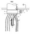
- FIG. 1an optical cable 1 is shown, which with a Interception device is intercepted according to the invention.
- the central element 3 of the optical cable 1inserted into the clamping end 7 of a clamping element 13 is.
- the upper end 16 of the clamping endis again after bent inward to improve introduction.
- About the Clamping end 7is pushed onto the clamping sleeve 8, as a result of which the Clamping to the central element 3 takes place.
- Via an intermediate piece 5is the clamping end 7 from the center of the Cable led to the outside and with its fixing 6 am Holding element 11 fixed.
- the holding element 11is now over a cable clamp 9 on the remote cable end 4 by means of a turnbuckle fixed.
- the definition of the holding element 11 on a mounting base 12can for example by means of screws or clamping. If the mounting base consists of conductive material, can simultaneously Earth potential can be connected.
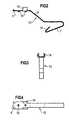
- FIG. 2shows the clamping element 13, which from the clamping end 7 with its end bend 16, the execution intermediate piece 5 and the fixing 6.
- the clamping end 7is bent in a U-shape, initially opened at an angle and is also used With the help of the sleeve to be pushed over the central element on the cable. Through the inflection 16 an adaptation to different central element diameters ensures, after sliding the sleeve 8 a non-positive connection between the clamping element 13 and Central element exists.
- the angular design intermediate piece 5serves the execution of the clamping end from the Center of the cable to the outside area and can accordingly the strength of the cable more or less bent out and thus be adjusted.
- the fixing 6is designed with locking lugs, which ensure a latching connection to the holding element.
- the fixing 6 with contact claws 15thprovided, which engage in the cable shield of the cable and thus a reliable contact as well as an increased Ensure grip.
- a U-shaped guide 14 am Fixing 6the holding element is inserted and secured against rotation held. By locking the fixatives 6 is no longer slipping when tensile forces occur possible.
- FIG. 3shows the clamping element 13 in a front view, in particular the formation of the guide 14 in appearance occurs. This is bent inwards at the top, so that the Holding element is secured.
- the clamping element 13is shown in a plan view, where the lateral arrangement of the locking lugs on Fixing 6 becomes clear.
- the contact claws or openings 15 and the guide 14 for the holding elementvisible.
- FIG. 5shows the holding element 11 that emerges from the contact surface 17 and the mounting surface 18 for the clamping element 13 exists.
- the holding element 11is on a Attachment base 12 attached so that this connection occurring forces and moments can be absorbed.
- Figure 6shows the side view of the holding element 11, wherein here the mounting surface 18 is clearly visible, on which the Holding element 11 is pushed and on which the settled Cable 1 is then placed so that it with the setting edge on End stop 19 of the mounting surface 18 comes to rest and attached with a cable tie or a hose clamp becomes. Then the central element is in the clamping end of the Inserted holding element and fixed with the sleeve.
- Figure 7shows the top view of the holding element 11, wherein especially here the insertion point 20 for the U-shaped Guide 14 of the clamping element can be seen.
- the clamping elementis with the U-shaped guide 14 at the insertion point 20 placed on the mounting surface 18 and then in Moved towards the end stop 19 so that when concerns the U-shaped guide 14 of the clamping element 13 at the end stops 19 of the holding element 11 through the fixing 6 Spring action snap up and thus a safe Fixing the clamping element 13 on the holding element 11 guarantee.
Landscapes
- Physics & Mathematics (AREA)
- General Physics & Mathematics (AREA)
- Optics & Photonics (AREA)
- Light Guides In General And Applications Therefor (AREA)
- Communication Cables (AREA)
- Insulated Conductors (AREA)
- Glass Compositions (AREA)
- Clamps And Clips (AREA)
- Cable Accessories (AREA)
- Installation Of Indoor Wiring (AREA)
Abstract
Description
Translated fromGermanDie Erfindung betrifft eine Abfangvorrichtung mit einemKlemmelement zum Anbringen einer mechanischen Verbindung amzugfesten Zentralelement eines optischen Kabels, wobei dasKlemmelement ein U-förmig gestaltetes Klemmende, eine auf dasKlemmende aufschiebbare Hülse, ein Fixierende und ein dasKlemmende und das Fixierende verbindendes Ausführungszwischenstückaufweist, wobei das Klemmelement an einem Halteelementgefaßt ist, das Halteelement mit Hilfe einer Klemmungam Kabelende und weiterhin an einer Befestigungsbasis fixierbarist.The invention relates to an interception device with aClamping element for attaching a mechanical connection to thetensile central element of an optical cable, theClamping element has a U-shaped clamping end, one on theClamping push-on sleeve, a fixing and thatClamping and connecting intermediate connecting piecehas, wherein the clamping element on a holding elementis captured, the holding element with the aid of a clampat the end of the cable and still fixable on a mounting baseis.
Eine Vorrichtung dieser Art ist aus der deutschen Offenlegungsschrift37 26 718 A1 bekannt. Dort wird das Zentralelementdes optischen Kabels mit relativ unhandlichen Schraubklemmen,Gewindebolzen und dergleichen gegen das Herauswanderngesichert und kontaktiert. Ein solcher Aufbau ist jedochbei Kabeln mit vielen Hohladern sehr schwierig und zeitaufwendigzu installieren, wobei beim Hantieren mit Werkzeugenim Zentrum der Hohladern die Gefahr von Verletzungen besteht.A device of this type is from the German published application37 26 718 A1 known. There becomes the central elementthe optical cable with relatively bulky screw terminals,Threaded bolts and the like against migrationsecured and contacted. However, such a structure isvery difficult and time-consuming for cables with many hollow coresto install, while handling toolsthere is a risk of injury in the center of the veins.
Aus DE 42 31 181 C1 ist eine Kabelabfangung für ein Kabel miteinem zugfesten Zentralelement bekannt. Das Zentralelementwird mit einer PUK-Schelle, die auf einer ersten Abfangungsleistebefestigt ist, festgeklemmt, während das Zentralelementin einer Bohrung einer zweiten Abfangungsleiste durchBefestigungsschrauben gehalten wird.From DE 42 31 181 C1 is a cable clamp for a cableknown a tensile central element. The central elementcomes with a PUK clamp on a first support railis attached, clamped while the central elementin a hole in a second strain reliefFastening screws is held.
Weiterhin ist aus DE 36 24 514 A1 eine Vorrichtung zur zugfestenVerkappung von Kabeln bekannt. Hier handelt es sich umeinen haubenförmigen Abschlußkörper mit Teilbereichen auswärmerückstellfähigem Kunststoff, in dem eine Zugöse eingesetztist.Furthermore, DE 36 24 514 A1 describes a device for tensile strengthCapping of cables known. This is abouta hood-shaped end body with sectionsheat-resilient plastic, in which a towing eye is usedis.
Aufgabe der Erfindung ist nun, eine Abfangvorrichtung für daszugfeste Zentralelement eines optischen Kabels zu finden, daseinfach und relativ unkompliziert zwischen den Hohladerngefaßt und fixiert werden kann. Die gestellte Aufgabe wirdnun mit einer Abfangvorrichtung der eingangs erläuterten Artdadurch gelöst, daß das Zwischenstück das Klemmende mit demFixierende direkt verbindet, daß das Zwischenstück in bezugauf die longitudinale Richtung des Kabels zur Anpassung anverschiedene Kabelstärken abgewinkelt angeordnet ist undausgebogen werden kann, um das Klemmende auf das Zentralelementdes Kabels aufzuschieben.The object of the invention is now a trapping device for theto find tensile central element of an optical cable thatsimple and relatively uncomplicated between the veinscan be grasped and fixed. The task posednow with an interception device of the type mentionedsolved in that the intermediate piece the clamping end with theFixing directly connects that to the intermediate pieceto adjust the longitudinal direction of the cabledifferent cable thicknesses is angled andcan be bent out to the clamping end on the central elementto postpone the cable.
Mit einer Abfangvorrichtung gemäß der Erfindung wird nun dasHerauswandern des Zentralelements aus einem optischen Kabel, hervorgerufen durch Temperaturschwankungen, Kabelbewegungenoder dergleichen, verhindert. Außerdem besteht die Möglichkeit,daß mit einer derartigen Vorrichtung ein metallischesZentralelement geerdet werden kann. Damit ist also eineelektrische wie auch eine mechanische Verbindung zum Zentralelementmöglich, wobei zusätzlich aufgrund der Ausformung desKlemmelementes der Kabelschirm des optischen Kabels miterfaßt werden kann. Außerdem wird eine mechanische Verbindungdes Kabelmantels mit einem metallischen oder nichtmetallischenZentralelement zu einer Befestigungsbasis ermöglicht.With an interception device according to the inventionMoving the central element out of an optical cable,caused by temperature fluctuations, cable movementsor the like prevented. There is also the possibilitythat with such a device a metallicCentral element can be grounded. So that's oneelectrical as well as a mechanical connection to the central elementpossible, in addition due to the shape of theClamping element with the cable shield of the optical cablecan be detected. It also creates a mechanical connectionof the cable sheath with a metallic or non-metallicCentral element to a mounting base allows.
So wird nun vor der Montage der Abfangvorrichtung gemäß derErfindung das Klemmelement am Halteelement angesetzt undeingerastet. Danach wird das Halteelement lose an der Befestigungsbasisin beliebiger Art montiert. Die Absetzkante desoptischen Kabels wird dabei bis an das Ende des Halteelementsgelegt. Das Halteelement wird dann mit dem optischen Kabelzusammen ausgerichtet und an der Befestigungsbasis fixiert.Das Klemmelement wird nun zwischen den Hohladern des optischenKabels neben dem Zentralelement positioniert. Anschließendwird das Zentralelement mit einem geeigneten Werkzeugauf die vom Klemmende des Klemmelements vorgegebene Längegekürzt. Das Klemmelement wird dann seitlich über das Zentralelementgesetzt und von vorne wird hierüber eine Hülsefür eine klemmende Befestigung miteinander aufgeschoben. Dasoptische Kabel wird nun mit Hilfe eines Kabelbinders odereiner Schlauchschelle am Halteelement festgelegt. Zur Kontaktierungdes Kabelschirms ist jedoch die Befestigung mittelseiner Schlauchschelle besser geeignet als mit einem Kunststoffkabelbinder.So now before the assembly of the interception device according to theInvention, the clamping element attached to the holding element andsnapped into place. After that, the holding element becomes loose on the fastening baseassembled in any way. The setting edge of theOptical cable is up to the end of the holding elementplaced. The holding element is then connected to the optical cablealigned together and fixed to the mounting base.The clamping element is now between the hollow wires of the opticalCable positioned next to the central element. Subsequentlythe central element with a suitable toolto the length specified by the clamping end of the clamping elementshortened. The clamping element is then laterally over the central elementand a sleeve is placed over it from the frontpushed together for a clamping attachment. Theoptical cable is now using a cable tie ora hose clamp on the holding element. For contactingthe cable shield is, however, the means of attachmenta hose clamp is more suitable than with a plastic cable tie.
Der Vorteil dieser Abfangvorrichtung gemäß der Erfindung istnun besonders darin zu sehen, daß das Klemmelement sehrschmal ist und gut von außen zwischen die Hohladern bzw.Adern des Kabels einzufügen ist. Auch die Hülse zur klemmendenBefestigung und Kontaktierung des Zentralelements desKabels fügt sich als runder Körper gut zwischen die Hohladern bzw. Adern ein. Außerdem wird kein Werkzeug für die Befestigungdes Zentralelementes zwischen den Hohladern hindurchgeführt,so daß keine Verletzungsgefahr gegeben ist.The advantage of this interception device according to the invention isnow especially to be seen in the fact that the clamping element very muchis narrow and well from the outside between the veins orWires of the cable must be inserted. Also the sleeve for clampingFastening and contacting the central element of theAs a round body, the cable fits well between the hollow wiresor veins. Also, there is no tool for attachmentof the central element passed between the hollow cores,so that there is no risk of injury.
Die Erfindung wird nun anhand von sieben Figuren näher erläutert.
- Figur 1
- zeigt die fertigmontierte Abfangvorrichtung gemäßder Erfindung.
Figur 2- zeigt das Klemmelement der Abfangvorrichtung ineiner Seitenansicht.
- Figur 3
- zeigt das Klemmelement in einer Frontansicht.
Figur 4- zeigt das Klemmelement in einer Draufsicht.
Figur 5- zeigt das Halteelement der Abfangvorrichtung.
Figur 6- zeigt das Halteelement in seitlicher Ansicht.
Figur 7- zeigt das Halteelement in einer Draufsicht.
- Figure 1
- shows the fully assembled interception device according to the invention.
- Figure 2
- shows the clamping element of the interception device in a side view.
- Figure 3
- shows the clamping element in a front view.
- Figure 4
- shows the clamping element in a plan view.
- Figure 5
- shows the holding element of the interception device.
- Figure 6
- shows the holding element in a side view.
- Figure 7
- shows the holding element in a plan view.
In Figur 1 wird ein optisches Kabel 1 gezeigt, das mit einerAbfangvorrichtung gemäß der Erfindung abgefangen wird. Darausist erkennbar, daß das Zentralelement 3 des optischen Kabels1 in das Klemmende 7 eines Klemmelements 13 klemmend eingeführtist. Das obere Ende 16 des Klemmendes ist nochmals nacheinwärts umgebogen, um die Einführung zu verbessern. Über dasKlemmende 7 ist die Klemmhülse 8 aufgeschoben, wodurch dieVerklemmung zum Zentralelement 3 erfolgt. Über ein Ausführungszwischenstück5 wird das Klemmende 7 aus dem Zentrum desKabels nach außen geführt und mit seinem Fixierende 6 amHalteelement 11 fixiert. Das Halteelement 11 wird nun übereine Kabel schelle 9 auf dem abgesetzten Kabelende 4 mittelseines Spannschlosses fixiert. Die Festlegung des Halteelements11 an einer Befestigungsbasis 12 kann beispielsweise mittels Schrauben oder Klemmung erfolgen. Wenn die Befestigungsbasisaus leitendem Material besteht, kann gleichzeitigErdpotential angeschlossen werden.In Figure 1, an optical cable 1 is shown, which with aInterception device is intercepted according to the invention. Out of itit can be seen that the central element 3 of the optical cable1 inserted into the clamping
Die Figur 2 zeigt das Klemmelement 13, das aus dem Klemmende7 mit seiner endseitigen Einbiegung 16, dem Ausführungszwischenstück5 und dem Fixierende 6 besteht. Das Klemmende 7ist U-förmig gebogen, zunächst winkelig geöffnet und wird mitHilfe der überzuschiebenden Hülse klemmend auf das Zentralelementdes Kabels aufgeschoben. Durch die Einbiegung 16 isteine Anpassung an verschiedene Zentralelement-Durchmessergewährleistet, wobei nach dem Aufschieben der Hülse 8 einekraftschlüssige Verbindung zwischen Klemmelement 13 undZentralelement besteht. Das winkelig angesetzte Ausführungszwischenstück5 dient der Ausführung des Klemmendes aus demZentrum des Kabels zum Außenbereich hin und kann entsprechendder Stärke des Kabels mehr oder weniger ausgebogen und damitangepaßt werden. Das Fixierende 6 ist mit Rastnasen ausgebildet,die eine rastende Verbindung zum Halteelement sicherstellen.Außerdem ist das Fixierende 6 mit Kontaktkrallen 15versehen, die in den Kabelschirm des Kabels eingreifen undsomit eine sichere Kontaktierung wie auch eine erhöhteGriffigkeit sicherstellen. In eine U-förmige Führung 14 amFixierende 6 wird das Halteelement eingeschoben und verdrehungssichergehalten. Durch das Einrasten der Fixierenden6 ist ein Abrutschen bei auftretenden Zugkräften nicht mehrmöglich.Figure 2 shows the
Die Figur 3 zeigt das Klemmelement 13 in einer Frontansicht,wobei besonders die Ausbildung der Führung 14 in Erscheinungtritt. Diese ist oben nach einwärts eingebogen, so daß dasHalteelement gesichert ist.FIG. 3 shows the clamping
In Figur4 wird das Klemmelement 13 in einer Draufsicht gezeigt,wobei hier die seitliche Anordnung der Rastnasen amFixierende 6 deutlich wird. Außerdem sind die Kontaktkrallen bzw. Durchrisse 15 und die Führung 14 für das Halteelementsichtbar.In Figure 4, the clamping
Die Figur 5 zeigt das Halteelement 11, das aus der Anlagefläche17 und der Befestigungsfläche 18 für das Klemmelement13 besteht.FIG. 5 shows the holding
Mittels der Anlagefläche 17 wird das Halteelement 11 an einerBefestigungsbasis 12 befestigt, so daß über diese Verbindungauftretende Kräfte und Momente abgefangen werden können.By means of the
Figur 6 zeigt die Seitenansicht des Halteelements 11, wobeihier die Befestigungsfläche 18 gut zu sehen ist, auf die dasHalteelement 11 aufgeschoben wird und an der das abgesetzteKabel 1 dann so angelegt wird, daß es mit der Absetzkante amEndanschlag 19 der Befestigungsfläche 18 zu liegen kommt undmit einem Kabelbinder oder einer Schlauchschelle befestigtwird. Daraufhin wird das Zentralelement in das Klemmende desHalteelements eingeführt und mit der Hülse fixiert.Figure 6 shows the side view of the holding
Die Fgur 7 zeigt die Draufsicht des Halteelementes 11, wobeiinsbesondere hier die Einführungsstelle 20 für die U-förmigeFührung 14 des Klemmelementes zu sehen ist. Das Klemmelementwird mit der U-förmigen Führung 14 an der Einführungsstelle20 auf die Befestigungsfläche 18 aufgesetzt und dann inRichtung des Endanschlags 19 verschoben, so daß bei Anliegender U-förmigen Führung 14 des Klemmelements 13 an den Endanschlägen19 des Halteelements 11 die Fixierenden 6 durchFederwirkung nach oben rasten und somit eine sichereFixierung des Klemmelements 13 auf dem Halteelement 11gewährleisten.Figure 7 shows the top view of the holding
Claims (8)
- Supporting device having a clamping element(13) for fitting a mechanical joint on a tension-proofcentral element (3) of an optical cable (1), theclamping element (13) having a clamping end (7) ofU-shaped configuration, a sleeve (8) which can bepushed onto the clamping end (7), a fixing end (6) anda lead-out adapter (5) connecting the clamping end (7)and the fixing end (6), the clamping element (13) beingmounted on a holding element (11) and it being possiblefor the holding element (11) to be fixed on the cableend (4) and, furthermore, on a fastening base (12) withthe aid of a clamp (9-10), characterized in that theadapter (5) directly connects the clamping end (7) tothe fixing end (6), and in that the adapter (5) isarranged angled away with reference to the longitudinaldirection of the cable for the purpose of adaptation todifferent cable thicknesses and can be bent out inorder to push the clamping end (7) onto the centralelement (3) of the cable.
- Supporting device according to Claim 1,characterized in that the fixing end (6) can be latchedtight on the holding element (11).
- Supporting device according to one of thepreceding claims, characterized in that the clampingend (7) has an inwardly bent termination and/or abent-in part (16).
- Supporting device according to one of thepreceding claims, characterized in that the fixing end(6) additionally has a U-shaped guide (14) for theholding element (11).
- Supporting device according to one of thepreceding claims, characterized in that the fixing end(6) has contact claws (15) directed towards the exposedcable shield of the cable end (4).
- Supporting device according to one of thepreceding claims, characterized in that the clamp(9-10) comprises a clamping band (9) and a turnbuckle(10).
- Supporting device according to one of thepreceding claims, characterized in that the holdingelement (11) is arranged on the fastening base (12) bymeans of screwing elements.
- Supporting device according to one of thepreceding claims, characterized in that the holdingelement (11) has an earth connection.
Applications Claiming Priority (2)
| Application Number | Priority Date | Filing Date | Title |
|---|---|---|---|
| DE4425925 | 1994-07-21 | ||
| DE4425925 | 1994-07-21 |
Publications (2)
| Publication Number | Publication Date |
|---|---|
| EP0693699A1 EP0693699A1 (en) | 1996-01-24 |
| EP0693699B1true EP0693699B1 (en) | 1999-12-01 |
Family
ID=6523841
Family Applications (1)
| Application Number | Title | Priority Date | Filing Date |
|---|---|---|---|
| EP95110348AExpired - LifetimeEP0693699B1 (en) | 1994-07-21 | 1995-07-03 | Anchoring device for optical cables |
Country Status (5)
| Country | Link |
|---|---|
| US (1) | US5638482A (en) |
| EP (1) | EP0693699B1 (en) |
| AT (1) | ATE187256T1 (en) |
| DE (1) | DE59507311D1 (en) |
| DK (1) | DK0693699T3 (en) |
Cited By (3)
| Publication number | Priority date | Publication date | Assignee | Title |
|---|---|---|---|---|
| US7783152B2 (en) | 2006-04-11 | 2010-08-24 | Ccs Technology, Inc. | Apparatus for restraining fiber optic cables |
| US7787740B2 (en) | 2008-06-12 | 2010-08-31 | Corning Cable Systems Llc | Universal cable bracket |
| US8055114B2 (en) | 2006-05-30 | 2011-11-08 | Ccs Technology, Inc. | Cable sleeve for the structured storage and handling of optical waveguides guided in optical waveguide cables |
Families Citing this family (51)
| Publication number | Priority date | Publication date | Assignee | Title |
|---|---|---|---|---|
| ES2251006T3 (en)* | 1996-08-28 | 2006-04-16 | Ccs Technology, Inc. | TERMINATION ELEMENT FOR A CENTRAL ELEMENT OF AN OPTICAL CABLE AND PROCEDURE TO ESTABLISH A HERMETIC CABLE ENTRY. |
| DE19820027A1 (en)* | 1998-05-05 | 1999-11-11 | Siemens Ag | Optical waveguide cable catching apparatus |
| JP3715825B2 (en)* | 1998-08-06 | 2005-11-16 | アルプス電気株式会社 | Optical fiber fixing device |
| US6198580B1 (en) | 1998-08-17 | 2001-03-06 | Newport Corporation | Gimballed optical mount |
| US6516130B1 (en) | 1998-12-30 | 2003-02-04 | Newport Corporation | Clip that aligns a fiber optic cable with a laser diode within a fiber optic module |
| FR2790115B1 (en) | 1999-02-23 | 2001-05-04 | Micro Controle | METHOD AND DEVICE FOR MOVING A MOBILE ON AN ELASTICALLY MOUNTED BASE |
| US6996506B2 (en)* | 1999-02-23 | 2006-02-07 | Newport Corporation | Process and device for displacing a moveable unit on a base |
| US6511035B1 (en) | 1999-08-03 | 2003-01-28 | Newport Corporation | Active vibration isolation systems with nonlinear compensation to account for actuator saturation |
| US6655840B2 (en) | 2001-02-13 | 2003-12-02 | Newport Corporation | Stiff cross roller bearing configuration |
| US6601524B2 (en) | 2001-03-28 | 2003-08-05 | Newport Corporation | Translation table with a spring biased dovetail bearing |
| US6791058B2 (en) | 2001-04-25 | 2004-09-14 | Newport Corporation | Automatic laser weld machine for assembling photonic components |
| US6568666B2 (en) | 2001-06-13 | 2003-05-27 | Newport Corporation | Method for providing high vertical damping to pneumatic isolators during large amplitude disturbances of isolated payload |
| US6619611B2 (en) | 2001-07-02 | 2003-09-16 | Newport Corporation | Pneumatic vibration isolator utilizing an elastomeric element for isolation and attenuation of horizontal vibration |
| US6966535B2 (en)* | 2002-05-07 | 2005-11-22 | Newport Corporation | Snubber for pneumatically isolated platforms |
| US7320455B2 (en) | 2003-10-24 | 2008-01-22 | Newport Corporation | Instrumented platform for vibration-sensitive equipment |
| US8231098B2 (en) | 2004-12-07 | 2012-07-31 | Newport Corporation | Methods and devices for active vibration damping of an optical structure |
| US8452148B2 (en) | 2008-08-29 | 2013-05-28 | Corning Cable Systems Llc | Independently translatable modules and fiber optic equipment trays in fiber optic equipment |
| US11294136B2 (en) | 2008-08-29 | 2022-04-05 | Corning Optical Communications LLC | High density and bandwidth fiber optic apparatuses and related equipment and methods |
| EP2221932B1 (en) | 2009-02-24 | 2011-11-16 | CCS Technology Inc. | Holding device for a cable or an assembly for use with a cable |
| US8699838B2 (en) | 2009-05-14 | 2014-04-15 | Ccs Technology, Inc. | Fiber optic furcation module |
| US8538226B2 (en) | 2009-05-21 | 2013-09-17 | Corning Cable Systems Llc | Fiber optic equipment guides and rails configured with stopping position(s), and related equipment and methods |
| US9075216B2 (en) | 2009-05-21 | 2015-07-07 | Corning Cable Systems Llc | Fiber optic housings configured to accommodate fiber optic modules/cassettes and fiber optic panels, and related components and methods |
| EP2443497B1 (en) | 2009-06-19 | 2020-03-04 | Corning Cable Systems LLC | High density and bandwidth fiber optic apparatus |
| WO2010148325A1 (en) | 2009-06-19 | 2010-12-23 | Corning Cable Systems Llc | High fiber optic cable packing density apparatus |
| US8712206B2 (en) | 2009-06-19 | 2014-04-29 | Corning Cable Systems Llc | High-density fiber optic modules and module housings and related equipment |
| US8625950B2 (en) | 2009-12-18 | 2014-01-07 | Corning Cable Systems Llc | Rotary locking apparatus for fiber optic equipment trays and related methods |
| US8992099B2 (en) | 2010-02-04 | 2015-03-31 | Corning Cable Systems Llc | Optical interface cards, assemblies, and related methods, suited for installation and use in antenna system equipment |
| US8913866B2 (en) | 2010-03-26 | 2014-12-16 | Corning Cable Systems Llc | Movable adapter panel |
| CA2796221C (en) | 2010-04-16 | 2018-02-13 | Ccs Technology, Inc. | Sealing and strain relief device for data cables |
| EP2381284B1 (en) | 2010-04-23 | 2014-12-31 | CCS Technology Inc. | Under floor fiber optic distribution device |
| US8705926B2 (en) | 2010-04-30 | 2014-04-22 | Corning Optical Communications LLC | Fiber optic housings having a removable top, and related components and methods |
| US9075217B2 (en) | 2010-04-30 | 2015-07-07 | Corning Cable Systems Llc | Apparatuses and related components and methods for expanding capacity of fiber optic housings |
| US9720195B2 (en) | 2010-04-30 | 2017-08-01 | Corning Optical Communications LLC | Apparatuses and related components and methods for attachment and release of fiber optic housings to and from an equipment rack |
| US8660397B2 (en) | 2010-04-30 | 2014-02-25 | Corning Cable Systems Llc | Multi-layer module |
| US8879881B2 (en) | 2010-04-30 | 2014-11-04 | Corning Cable Systems Llc | Rotatable routing guide and assembly |
| US9632270B2 (en) | 2010-04-30 | 2017-04-25 | Corning Optical Communications LLC | Fiber optic housings configured for tool-less assembly, and related components and methods |
| US9519118B2 (en) | 2010-04-30 | 2016-12-13 | Corning Optical Communications LLC | Removable fiber management sections for fiber optic housings, and related components and methods |
| US8718436B2 (en) | 2010-08-30 | 2014-05-06 | Corning Cable Systems Llc | Methods, apparatuses for providing secure fiber optic connections |
| US9279951B2 (en) | 2010-10-27 | 2016-03-08 | Corning Cable Systems Llc | Fiber optic module for limited space applications having a partially sealed module sub-assembly |
| US9116324B2 (en) | 2010-10-29 | 2015-08-25 | Corning Cable Systems Llc | Stacked fiber optic modules and fiber optic equipment configured to support stacked fiber optic modules |
| US8662760B2 (en) | 2010-10-29 | 2014-03-04 | Corning Cable Systems Llc | Fiber optic connector employing optical fiber guide member |
| CA2819235C (en) | 2010-11-30 | 2018-01-16 | Corning Cable Systems Llc | Fiber device holder and strain relief device |
| WO2012106510A2 (en) | 2011-02-02 | 2012-08-09 | Corning Cable Systems Llc | Dense fiber optic connector assemblies and related connectors and cables suitable for establishing optical connections for optical backplanes in equipment racks |
| US9008485B2 (en) | 2011-05-09 | 2015-04-14 | Corning Cable Systems Llc | Attachment mechanisms employed to attach a rear housing section to a fiber optic housing, and related assemblies and methods |
| AU2012275598A1 (en) | 2011-06-30 | 2014-01-16 | Corning Optical Communications LLC | Fiber optic equipment assemblies employing non-U-width-sized housings and related methods |
| US8953924B2 (en) | 2011-09-02 | 2015-02-10 | Corning Cable Systems Llc | Removable strain relief brackets for securing fiber optic cables and/or optical fibers to fiber optic equipment, and related assemblies and methods |
| US9038832B2 (en) | 2011-11-30 | 2015-05-26 | Corning Cable Systems Llc | Adapter panel support assembly |
| US9250409B2 (en) | 2012-07-02 | 2016-02-02 | Corning Cable Systems Llc | Fiber-optic-module trays and drawers for fiber-optic equipment |
| US9042702B2 (en) | 2012-09-18 | 2015-05-26 | Corning Cable Systems Llc | Platforms and systems for fiber optic cable attachment |
| ES2551077T3 (en) | 2012-10-26 | 2015-11-16 | Ccs Technology, Inc. | Fiber optic management unit and fiber optic distribution device |
| US8985862B2 (en) | 2013-02-28 | 2015-03-24 | Corning Cable Systems Llc | High-density multi-fiber adapter housings |
Family Cites Families (5)
| Publication number | Priority date | Publication date | Assignee | Title |
|---|---|---|---|---|
| DE3726718A1 (en) | 1986-04-07 | 1989-02-23 | Siemens Ag | DEVICE FOR ATTACHING A MECHANICAL CONNECTION TO THE CABLE SHEATH OF AN OPTICAL CABLE |
| DE3726719A1 (en)* | 1986-04-07 | 1989-02-23 | Siemens Ag | DEVICE FOR ATTACHING A MECHANICAL CONNECTION TO THE CABLE SHEATH OF AN OPTICAL CABLE |
| DE3624514A1 (en)* | 1986-07-19 | 1988-01-28 | Rose Walter Gmbh & Co Kg | Device for the tension-resistant capping of cables |
| JPH03191303A (en)* | 1989-12-20 | 1991-08-21 | Sumitomo Electric Ind Ltd | Casing pass-through part of optical fiber cable |
| DE4231181C1 (en)* | 1992-09-17 | 1993-08-26 | Siemens Ag, 8000 Muenchen, De | Cable restraint for fibre=optic cable distribution box - comprises U=shaped fixing shell fastened to rail which mounts screw for fixing cable central strain element |
- 1995
- 1995-07-03EPEP95110348Apatent/EP0693699B1/ennot_activeExpired - Lifetime
- 1995-07-03DKDK95110348Tpatent/DK0693699T3/enactive
- 1995-07-03DEDE59507311Tpatent/DE59507311D1/ennot_activeExpired - Fee Related
- 1995-07-03ATAT95110348Tpatent/ATE187256T1/ennot_activeIP Right Cessation
- 1995-07-11USUS08/500,588patent/US5638482A/ennot_activeExpired - Fee Related
Cited By (3)
| Publication number | Priority date | Publication date | Assignee | Title |
|---|---|---|---|---|
| US7783152B2 (en) | 2006-04-11 | 2010-08-24 | Ccs Technology, Inc. | Apparatus for restraining fiber optic cables |
| US8055114B2 (en) | 2006-05-30 | 2011-11-08 | Ccs Technology, Inc. | Cable sleeve for the structured storage and handling of optical waveguides guided in optical waveguide cables |
| US7787740B2 (en) | 2008-06-12 | 2010-08-31 | Corning Cable Systems Llc | Universal cable bracket |
Also Published As
| Publication number | Publication date |
|---|---|
| EP0693699A1 (en) | 1996-01-24 |
| ATE187256T1 (en) | 1999-12-15 |
| DK0693699T3 (en) | 2000-05-29 |
| US5638482A (en) | 1997-06-10 |
| DE59507311D1 (en) | 2000-01-05 |
Similar Documents
| Publication | Publication Date | Title |
|---|---|---|
| EP0693699B1 (en) | Anchoring device for optical cables | |
| DE2943180C2 (en) | Fiber optic connector | |
| EP1317025B1 (en) | Heavy duty connection device for data cable, more especially RJ-45-connector | |
| DE19734269A1 (en) | Construction for installing bundle of conductors in vehicle door | |
| DE3318248A1 (en) | MULTIPOLE ELECTRICAL PLUG, IN PARTICULAR ROUND PLUG | |
| DE69014410T2 (en) | Cable connector device. | |
| DE69511766T2 (en) | Cable strain relief device for forming a rear fastening for a connector | |
| DE19528552A1 (en) | Coaxial connector for high-frequency (HF) cable signal transmission | |
| DE4142642C2 (en) | Pipe / wire clamp assembly | |
| EP0435026B1 (en) | Connection clamp | |
| WO2018087211A1 (en) | Contact element comprising a clamping terminal for a stranded conductor | |
| DE4201390A1 (en) | Plug connector for multi-lead cable, e.g. for telephone subscriber's appts. - has plug block with contacts electrically connected to leads in grommet of cable | |
| DE19730269C2 (en) | Device for fastening a first part to a second part | |
| DE10008613C2 (en) | Transition piece | |
| DE4104530C1 (en) | Tensioning relief device for fibre=optic cable - incorporates sleeve which shrink fits onto end of cable | |
| EP3970573A1 (en) | Fixing device for a curtain rod | |
| DE19547231C2 (en) | Fastening device for cable connectors | |
| DE19841572C1 (en) | Pliable fastening strap for securing cable shielding to contact element, has primary tooth-like fasteners locking into each other while twisting around primary fasteners or secondary fasteners in overlapping area | |
| DE69126070T2 (en) | Fiber optic connector | |
| DE10258454B4 (en) | clamp | |
| DE2811241C2 (en) | Clamping device for connecting the cable sheath of a cable | |
| DE3611647A1 (en) | Device for attaching a mechanical connection to the sheath of a cable, preferably an optical fibre cable | |
| DE2801483C2 (en) | ||
| DE4039430C2 (en) | ||
| DE10121558C2 (en) | Holder for receiving a rod or tubular component for overhead contact line construction |
Legal Events
| Date | Code | Title | Description |
|---|---|---|---|
| PUAI | Public reference made under article 153(3) epc to a published international application that has entered the european phase | Free format text:ORIGINAL CODE: 0009012 | |
| AK | Designated contracting states | Kind code of ref document:A1 Designated state(s):AT BE DE DK FR GB IT NL SE | |
| 17P | Request for examination filed | Effective date:19960404 | |
| GRAG | Despatch of communication of intention to grant | Free format text:ORIGINAL CODE: EPIDOS AGRA | |
| 17Q | First examination report despatched | Effective date:19990401 | |
| GRAG | Despatch of communication of intention to grant | Free format text:ORIGINAL CODE: EPIDOS AGRA | |
| GRAH | Despatch of communication of intention to grant a patent | Free format text:ORIGINAL CODE: EPIDOS IGRA | |
| GRAH | Despatch of communication of intention to grant a patent | Free format text:ORIGINAL CODE: EPIDOS IGRA | |
| GRAA | (expected) grant | Free format text:ORIGINAL CODE: 0009210 | |
| AK | Designated contracting states | Kind code of ref document:B1 Designated state(s):AT BE DE DK FR GB IT NL SE | |
| REF | Corresponds to: | Ref document number:187256 Country of ref document:AT Date of ref document:19991215 Kind code of ref document:T | |
| REF | Corresponds to: | Ref document number:59507311 Country of ref document:DE Date of ref document:20000105 | |
| ITF | It: translation for a ep patent filed | ||
| GBT | Gb: translation of ep patent filed (gb section 77(6)(a)/1977) | Effective date:20000203 | |
| ET | Fr: translation filed | ||
| REG | Reference to a national code | Ref country code:DK Ref legal event code:T3 | |
| PLBE | No opposition filed within time limit | Free format text:ORIGINAL CODE: 0009261 | |
| STAA | Information on the status of an ep patent application or granted ep patent | Free format text:STATUS: NO OPPOSITION FILED WITHIN TIME LIMIT | |
| 26N | No opposition filed | ||
| PGFP | Annual fee paid to national office [announced via postgrant information from national office to epo] | Ref country code:SE Payment date:20010620 Year of fee payment:7 | |
| PGFP | Annual fee paid to national office [announced via postgrant information from national office to epo] | Ref country code:NL Payment date:20010621 Year of fee payment:7 Ref country code:AT Payment date:20010621 Year of fee payment:7 | |
| PGFP | Annual fee paid to national office [announced via postgrant information from national office to epo] | Ref country code:DK Payment date:20010622 Year of fee payment:7 | |
| REG | Reference to a national code | Ref country code:GB Ref legal event code:IF02 | |
| PG25 | Lapsed in a contracting state [announced via postgrant information from national office to epo] | Ref country code:AT Free format text:LAPSE BECAUSE OF NON-PAYMENT OF DUE FEES Effective date:20020703 | |
| PG25 | Lapsed in a contracting state [announced via postgrant information from national office to epo] | Ref country code:SE Free format text:LAPSE BECAUSE OF NON-PAYMENT OF DUE FEES Effective date:20020704 | |
| PG25 | Lapsed in a contracting state [announced via postgrant information from national office to epo] | Ref country code:DK Free format text:LAPSE BECAUSE OF NON-PAYMENT OF DUE FEES Effective date:20020731 | |
| PG25 | Lapsed in a contracting state [announced via postgrant information from national office to epo] | Ref country code:NL Free format text:LAPSE BECAUSE OF NON-PAYMENT OF DUE FEES Effective date:20030201 | |
| REG | Reference to a national code | Ref country code:DK Ref legal event code:EBP | |
| EUG | Se: european patent has lapsed | ||
| NLV4 | Nl: lapsed or anulled due to non-payment of the annual fee | Effective date:20030201 | |
| BECA | Be: change of holder's address | Owner name:*CCS TECHNOLOGY INC.103 FOULK ROAD, WILMINGTON, DE Effective date:20040119 | |
| BECH | Be: change of holder | Owner name:*CCS TECHNOLOGY INC. Effective date:20040119 | |
| REG | Reference to a national code | Ref country code:GB Ref legal event code:732E | |
| REG | Reference to a national code | Ref country code:FR Ref legal event code:TP Ref country code:FR Ref legal event code:CD | |
| PG25 | Lapsed in a contracting state [announced via postgrant information from national office to epo] | Ref country code:IT Free format text:LAPSE BECAUSE OF NON-PAYMENT OF DUE FEES;WARNING: LAPSES OF ITALIAN PATENTS WITH EFFECTIVE DATE BEFORE 2007 MAY HAVE OCCURRED AT ANY TIME BEFORE 2007. THE CORRECT EFFECTIVE DATE MAY BE DIFFERENT FROM THE ONE RECORDED. Effective date:20050703 | |
| PGFP | Annual fee paid to national office [announced via postgrant information from national office to epo] | Ref country code:FR Payment date:20090717 Year of fee payment:15 | |
| PGFP | Annual fee paid to national office [announced via postgrant information from national office to epo] | Ref country code:GB Payment date:20090727 Year of fee payment:15 Ref country code:DE Payment date:20090729 Year of fee payment:15 | |
| PGFP | Annual fee paid to national office [announced via postgrant information from national office to epo] | Ref country code:BE Payment date:20090818 Year of fee payment:15 | |
| BERE | Be: lapsed | Owner name:*CCS TECHNOLOGY INC. Effective date:20100731 | |
| GBPC | Gb: european patent ceased through non-payment of renewal fee | Effective date:20100703 | |
| REG | Reference to a national code | Ref country code:FR Ref legal event code:ST Effective date:20110331 | |
| PG25 | Lapsed in a contracting state [announced via postgrant information from national office to epo] | Ref country code:DE Free format text:LAPSE BECAUSE OF NON-PAYMENT OF DUE FEES Effective date:20110201 | |
| REG | Reference to a national code | Ref country code:DE Ref legal event code:R119 Ref document number:59507311 Country of ref document:DE Effective date:20110201 | |
| PG25 | Lapsed in a contracting state [announced via postgrant information from national office to epo] | Ref country code:FR Free format text:LAPSE BECAUSE OF NON-PAYMENT OF DUE FEES Effective date:20100802 | |
| PG25 | Lapsed in a contracting state [announced via postgrant information from national office to epo] | Ref country code:BE Free format text:LAPSE BECAUSE OF NON-PAYMENT OF DUE FEES Effective date:20100731 | |
| PG25 | Lapsed in a contracting state [announced via postgrant information from national office to epo] | Ref country code:GB Free format text:LAPSE BECAUSE OF NON-PAYMENT OF DUE FEES Effective date:20100703 |