EP0691138B1 - Magnetic cap for medical appliance - Google Patents
Magnetic cap for medical applianceDownload PDFInfo
- Publication number
- EP0691138B1 EP0691138B1EP95301897AEP95301897AEP0691138B1EP 0691138 B1EP0691138 B1EP 0691138B1EP 95301897 AEP95301897 AEP 95301897AEP 95301897 AEP95301897 AEP 95301897AEP 0691138 B1EP0691138 B1EP 0691138B1
- Authority
- EP
- European Patent Office
- Prior art keywords
- magnets
- cap
- lid body
- magnetic
- plug
- Prior art date
- Legal status (The legal status is an assumption and is not a legal conclusion. Google has not performed a legal analysis and makes no representation as to the accuracy of the status listed.)
- Expired - Lifetime
Links
- 230000000717retained effectEffects0.000claimsdescription11
- 230000004907fluxEffects0.000claimsdescription4
- 238000000034methodMethods0.000description8
- 210000002700urineAnatomy0.000description5
- BGPVFRJUHWVFKM-UHFFFAOYSA-NN1=C2C=CC=CC2=[N+]([O-])C1(CC1)CCC21N=C1C=CC=CC1=[N+]2[O-]Chemical compoundN1=C2C=CC=CC2=[N+]([O-])C1(CC1)CCC21N=C1C=CC=CC1=[N+]2[O-]BGPVFRJUHWVFKM-UHFFFAOYSA-N0.000description4
- 201000010099diseaseDiseases0.000description4
- 208000037265diseases, disorders, signs and symptomsDiseases0.000description4
- 210000003932urinary bladderAnatomy0.000description4
- 230000027939micturitionEffects0.000description3
- 210000003708urethraAnatomy0.000description3
- 206010021639IncontinenceDiseases0.000description2
- XEEYBQQBJWHFJM-UHFFFAOYSA-NIronChemical compound[Fe]XEEYBQQBJWHFJM-UHFFFAOYSA-N0.000description2
- 239000003795chemical substances by applicationSubstances0.000description2
- 238000013160medical therapyMethods0.000description2
- 210000000278spinal cordAnatomy0.000description2
- 206010003694AtrophyDiseases0.000description1
- 206010012289DementiaDiseases0.000description1
- BALXUFOVQVENIU-GNAZCLTHSA-NEphedrine hydrochlorideChemical compoundCl.CN[C@@H](C)[C@H](O)C1=CC=CC=C1BALXUFOVQVENIU-GNAZCLTHSA-N0.000description1
- 206010033799ParalysisDiseases0.000description1
- 208000028938Urination diseaseDiseases0.000description1
- 239000002160alpha blockerSubstances0.000description1
- 230000037444atrophyEffects0.000description1
- 210000004204blood vesselAnatomy0.000description1
- 230000002490cerebral effectEffects0.000description1
- 238000010276constructionMethods0.000description1
- 229940079593drugDrugs0.000description1
- 239000003814drugSubstances0.000description1
- 229960002534ephedrine hydrochlorideDrugs0.000description1
- BCGWQEUPMDMJNV-UHFFFAOYSA-NimipramineChemical compoundC1CC2=CC=CC=C2N(CCCN(C)C)C2=CC=CC=C21BCGWQEUPMDMJNV-UHFFFAOYSA-N0.000description1
- 229960004801imipramineDrugs0.000description1
- 229910052742ironInorganic materials0.000description1
- 238000004519manufacturing processMethods0.000description1
- 239000000463materialSubstances0.000description1
- 230000013011matingEffects0.000description1
- 210000003205muscleAnatomy0.000description1
- 210000004197pelvisAnatomy0.000description1
- 210000001215vaginaAnatomy0.000description1
- 210000003905vulvaAnatomy0.000description1
Images

Classifications
- A—HUMAN NECESSITIES
- A61—MEDICAL OR VETERINARY SCIENCE; HYGIENE
- A61M—DEVICES FOR INTRODUCING MEDIA INTO, OR ONTO, THE BODY; DEVICES FOR TRANSDUCING BODY MEDIA OR FOR TAKING MEDIA FROM THE BODY; DEVICES FOR PRODUCING OR ENDING SLEEP OR STUPOR
- A61M25/00—Catheters; Hollow probes
- A61M25/01—Introducing, guiding, advancing, emplacing or holding catheters
- A61M25/02—Holding devices, e.g. on the body
- A61M25/04—Holding devices, e.g. on the body in the body, e.g. expansible
- A—HUMAN NECESSITIES
- A61—MEDICAL OR VETERINARY SCIENCE; HYGIENE
- A61M—DEVICES FOR INTRODUCING MEDIA INTO, OR ONTO, THE BODY; DEVICES FOR TRANSDUCING BODY MEDIA OR FOR TAKING MEDIA FROM THE BODY; DEVICES FOR PRODUCING OR ENDING SLEEP OR STUPOR
- A61M39/00—Tubes, tube connectors, tube couplings, valves, access sites or the like, specially adapted for medical use
- A61M39/20—Closure caps or plugs for connectors or open ends of tubes
- B—PERFORMING OPERATIONS; TRANSPORTING
- B65—CONVEYING; PACKING; STORING; HANDLING THIN OR FILAMENTARY MATERIAL
- B65D—CONTAINERS FOR STORAGE OR TRANSPORT OF ARTICLES OR MATERIALS, e.g. BAGS, BARRELS, BOTTLES, BOXES, CANS, CARTONS, CRATES, DRUMS, JARS, TANKS, HOPPERS, FORWARDING CONTAINERS; ACCESSORIES, CLOSURES, OR FITTINGS THEREFOR; PACKAGING ELEMENTS; PACKAGES
- B65D47/00—Closures with filling and discharging, or with discharging, devices
- B65D47/04—Closures with discharging devices other than pumps
- B65D47/06—Closures with discharging devices other than pumps with pouring spouts or tubes; with discharge nozzles or passages
- B65D47/12—Closures with discharging devices other than pumps with pouring spouts or tubes; with discharge nozzles or passages having removable closures
- B65D47/14—Closures with discharging devices other than pumps with pouring spouts or tubes; with discharge nozzles or passages having removable closures and closure-retaining means
- B—PERFORMING OPERATIONS; TRANSPORTING
- B65—CONVEYING; PACKING; STORING; HANDLING THIN OR FILAMENTARY MATERIAL
- B65D—CONTAINERS FOR STORAGE OR TRANSPORT OF ARTICLES OR MATERIALS, e.g. BAGS, BARRELS, BOTTLES, BOXES, CANS, CARTONS, CRATES, DRUMS, JARS, TANKS, HOPPERS, FORWARDING CONTAINERS; ACCESSORIES, CLOSURES, OR FITTINGS THEREFOR; PACKAGING ELEMENTS; PACKAGES
- B65D2313/00—Connecting or fastening means
- B65D2313/04—Connecting or fastening means of magnetic type
Definitions
- This inventionrelates to a magnetic cap which serves as an external switch valve for a medical appliance to be retained in a human body (for example, a urethra catheter and the like).
- An object of the present inventionis provide a magnetic cap for a medical appliance to be retained in a human body, which can be readily handled for charging and discharge urine even by, for example, women who retain urine in their bladders find it difficult to discharge the urine and also for women who are unable to use urinary bladder bags or napkins.
- the pre-characterising portion of claim 1is known from US-A-4 163 722.
- the member carried by the lid bodycomprises a relatively short rigid projection.
- a disabled personhas difficulty in manipulating the member to open and close the body plug.
- a cap for a medical appliance to be retained in a human bodycomprises a lid body detachably coupled to a connecting body plug through a flexible band, and a member carried by the lid body by means of which the lid body can be removed from the body plug, characterised in that an annular magnet is secured to an upper face of the connecting plug body, a disk like magnet is secured to an upper face of the lid body, the magnets being set to be 5 to 15mm in diameter 0.5 to 5.0mm in thickness, and 1500 to 2000 gauss in magnetic flux density, and magnetic poles (S-N, N-S) on contact faces of the magnets being directed in opposition to each other, and the member comprises a strap for cooperation by the palm or finger of a disabled patient so that the magnets can be brought together or the lid body can be detached from the body plug.
- both magnetsare set to be 1500 to 2000 gauss in magnetic flux density, a mutual attraction force of the magnets becomes stronger and the cap is not disconnected from the connecting plug body in use.
- the patientwants to disconnect the cap, the patient can easily detach the cap from the plug body only be pulling the strap using their palm or finger. Since it is possible to detachably connect the connecting plug body
- the magnetic capcan be applied to the same or different kind of appliance.
- both magnetsare set to be 5 to 15mm in diameter and 0.5 to 5.0mm in thickness, the magnetic cap becomes relatively small size and does not impart any discomfort to the patient.
- FIGS. 1 through 3A and 3Ba magnetic cap 10 for a medical appliance to be retained in a human body in accordance with the present invention will be explained below.
- the magnetic cap 10 for a medical appliance to be retained in a human bodycomprises: an annular magnet 2 secured to an upper face of a connecting plug body 1; a disk like magnet 4 secured to an upper face of a lid body which is detachably coupled to the connecting body 1 through a flexible band 6; and a strap 5 attached to an end of the lid body 3.
- the magnets 2 and 4are set to be 5 to 15 mm in diameter, 0.5 to 5.0 mm in thickness, and 1500 to 2000 gauss in magnetic flux density. Magnetic poles on contact faces of the magnets 2 and 4 are directed in opposition to each other.
- the upper and lower faces of the annular magnet 2are set to be an S-pole and an N-pole while the upper and lower faces of the disk like magnet 4 are set to be an N-pole and an S-pole.
- both magnets 2 and 4contact with each other and attracts each other by their magnetic forces.
- both magnetsare aligned with the same center axis by their attraction forces immediately before the magnets contact with each other.
- one of the magnets 2 and 4is made of an iron material, they immediately contact with each other when they approach each other and thus they cannot adjust misalignment of their center axes automatically.
- FIGS. 4A and 4BThe magnetic cap 10 may be used as shown in FIGS. 4A and 4B.
- FIG. 4Ashows an example in which the magnetic cap 10 is attached to an external drain port of an usual urethra catheter 20.
- FIG. 4Bshows another example in which the magnetic cap 10 is attached to an external drain port of an usual MALECOT® catheter 30.
- connecting plug body shown in FIGS. 1 to 4is coupled to an inside of a port of a mating appliance
- a connecting plug body 1a with a magnetic cap 10a shown in FIG. 5is coupled to the outside of the port.
- a medical appliance, in particular, a MALECOT® catheter to which the magnetic cap of the present invention can be appliedis limited to the following diseases of patients:
- the magnetic cap of this inventioncan be utilized to a medical appliance to be retained in a human body over a wide scope, is simple in operation, and is superior in a closing function. Further, the cap has a simple construction and can be made at a low production cost.
Landscapes
- Health & Medical Sciences (AREA)
- Engineering & Computer Science (AREA)
- Heart & Thoracic Surgery (AREA)
- Life Sciences & Earth Sciences (AREA)
- Pulmonology (AREA)
- Anesthesiology (AREA)
- Biomedical Technology (AREA)
- Hematology (AREA)
- Animal Behavior & Ethology (AREA)
- General Health & Medical Sciences (AREA)
- Public Health (AREA)
- Veterinary Medicine (AREA)
- Mechanical Engineering (AREA)
- Biophysics (AREA)
- External Artificial Organs (AREA)
- Magnetic Treatment Devices (AREA)
- Media Introduction/Drainage Providing Device (AREA)
Description
- This invention relates to a magnetic cap which servesas an external switch valve for a medical appliance to beretained in a human body (for example, a urethra catheterand the like).
- Heretofore, there are the following examples ofmedical appliances which are retained in a human body.
- Various diseases involving incontinence affect women.Medical therapy including ubrechide, α-blocker and the likemay be applied and an intermittent self-withdrawing methodare now also widely effected. Also, a medical therapy(anticholine agent, imipramine, ephedrine hydrochloride, αactuation agent or the like), a balloon catheter retainingmethod, pelvis lower muscle training method, intermittentself-withdrawing method, urination method using a urinecollector or various kinds of napkins, and the like arealso employed in cases of incontinence. These methods haveprovided substantial benefits.
- On the other hand, in the case of damage to cerebralblood vessels on the spinal cord, to medication may beslow and people thus afflicted may have difficulty usinga catheter, consequently the above methods are not oftenapplied to these persons. In particular, women sufferingparalysis having diseases worse than a middle degree andupper spinal cord (higher than seventh cervical vertebrae)damaged women are treated only by a selectable urinationcontrol method such as utilization of urinary bladder bagsor napkins.
- An object of the present invention is providea magnetic cap for a medical appliance to be retained ina human body, which can be readily handled for charging anddischarge urine even by, for example, women who retain urinein their bladders find it difficult to discharge the urine and also for women who are unable to use urinary bladder bags ornapkins.
- The pre-characterising portion of claim 1 is known from US-A-4 163 722. In the cap disclosed in US-A-4 163 722the member carried by the lid body comprises a relatively short rigidprojection. In practice a disabled person has difficulty in manipulatingthe member to open and close the body plug.
- According to the invention, a cap for a medical appliance to beretained in a human body, comprises a lid body detachably coupled to aconnecting body plug through a flexible band, and a member carried bythe lid body by means of which the lid body can be removed from thebody plug, characterised in that an annular magnet is secured to an upperface of the connecting plug body, a disk like magnet is secured to anupper face of the lid body, the magnets being set to be 5 to 15mm indiameter 0.5 to 5.0mm in thickness, and 1500 to 2000 gauss in magneticflux density, and magnetic poles (S-N, N-S) on contact faces of themagnets being directed in opposition to each other, and the membercomprises a strap for cooperation by the palm or finger of a disabledpatient so that the magnets can be brought together or the lid body can bedetached from the body plug.
- Since both magnets are set to be 1500 to 2000 gauss in magneticflux density, a mutual attraction force of the magnets becomes strongerand the cap is not disconnected from the connecting plug body in use.However, in the case that the patient wants to disconnect the cap, thepatient can easily detach the cap from the plug body only be pulling thestrap using their palm or finger.Since it is possible to detachably connect the connecting plug body
- to a port of the medical appliance to be retained in the human body, themagnetic cap can be applied to the same or different kind of appliance.
- Since both magnets are set to be 5 to 15mm in diameter and 0.5 to5.0mm in thickness, the magnetic cap becomes relatively small size anddoes not impart any discomfort to the patient.
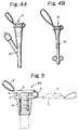
- FIG. 1 is a longitudinal sectional view of a magnetic cap of thepresent invention;
- FIG. 2 is a plan view of FIG. 1;
- FIG. 3A is a longitudinal sectional view of themagnetic cap, illustrating a closed state of the cap shownin FIG. 1;
- FIG. 3B is a longitudinal sectional view of a pairof magnets, illustrating an open position of the magnets;
- FIGS. 4A and 4B are side elevational views of medicalappliances to be retained in a human body, illustratingexamples of using the magnetic caps; and
- FIG. 5 is a longitudinal sectional view of analternation of the magnetic cap of the present invention.
- Referring now to FIGS. 1 through 3A and 3B,a
magnetic cap 10 for a medical appliance to be retained ina human body in accordance with the present invention willbe explained below. - The
magnetic cap 10 for a medical appliance to beretained in a human body, comprises: anannular magnet 2secured to an upper face of a connecting plug body 1; a disklikemagnet 4 secured to an upper face of a lid body whichis detachably coupled to the connecting body 1 throughaflexible band 6; and astrap 5 attached to an end ofthelid body 3. - The
magnets magnets annular magnet 2 are set to be an S-pole andan N-pole while the upper and lower faces of the disk likemagnet 4 are set to be an N-pole and an S-pole. - As shown in FIGS. 1 and 2, when the
magnetic cap 10is in an open position theannular magnet 2 releasesapassage 11 in the connecting plug body 1 while the disklikemagnet 4 is spaced away from the body 1. - As shown in FIG. 3A, when the magnetic cap is ina closed position, both
magnets - In the case that one of the
magnets - When the
magnetic cap 10 is in the closed position asshown in FIG. 3A, the disk likemagnet 4 closes thepassage 11 in the connecting plug body 1. - The
magnetic cap 10 may be used as shown in FIGS. 4Aand 4B. FIG. 4A shows an example in which themagnetic cap 10 is attached to an external drain port of anusual urethracatheter 20. FIG. 4B shows another example in which themagnetic cap 10 is attached to an external drain port ofan usual MALECOT®catheter 30. - Although the connecting plug body shown in FIGS. 1 to4 is coupled to an inside of a port of a mating appliance,a connecting plug body 1a with a
magnetic cap 10a shown inFIG. 5 is coupled to the outside of the port. - A medical appliance, in particular, a MALECOT®catheter to which the magnetic cap of the present inventioncan be applied is limited to the following diseases ofpatients:
- 1. It is preferable that the patient has a desire tourinate. It is not suitable for use in cases of dementia.
- 2. The patient can bring one's finger to the vulva.
- 3. A capacity of the urinary bladder must be more than150 ml.
- 4. The patient can take a balance upon opening the legsand setting on the legs.
- 5. It is not suitable for the patient who has anexternal port of the urethra in one's inner part or haspronounced vagina atrophy.
- 6. It is not suitable for a patient who feels thata balloon catheter retained in the body is an obstacle.
- 7. The patient may take a bath.
- 8. It is applicable for a patient who has difficulty inmoving ones fingers, has urination diseases or urine storagediseases.
- 9. The patient can urinate at a toilet under a conditionsimilar to natural urination.
- The magnetic cap of this invention can be utilizedto a medical appliance to be retained in a human body overa wide scope, is simple in operation, and is superiorin a closing function. Further, the cap has a simpleconstruction and can be made at a low production cost.
Claims (2)
- A cap for a medical appliance to be retained in a human body,comprising a lid body (3) detachably coupled to a connecting body plug (1)through a flexible band (6), and a member carried by the lid body (3) bymeans of which the lid body (3) can be removed from the body plug (1),characterised in that an annular magnet (2) is secured to an upper face ofthe connecting plug body (1), a disk like magnet (4) is secured to an upperface of the lid body (3), the magnets (2, 4) being set to be 5 to 15mm indiameter 0.5 to 5.0mm in thickness, and 1500 to 2000 gauss in magneticflux density, and magnetic poles (S-N, N-S) on contact faces of themagnets being directed in opposition to each other, and the membercomprises a strap (5) for co-operation by the palm or finger of a disabledpatient so that the magnets can be brought together or the lid body (3) can bedetached from the body plug (1).
- A cap according to Claim 1, in which the strap (5) is in the form of aclosed loop.
Applications Claiming Priority (2)
| Application Number | Priority Date | Filing Date | Title |
|---|---|---|---|
| JP152072/94 | 1994-07-04 | ||
| JP15207294 | 1994-07-04 |
Publications (2)
| Publication Number | Publication Date |
|---|---|
| EP0691138A1 EP0691138A1 (en) | 1996-01-10 |
| EP0691138B1true EP0691138B1 (en) | 1999-05-26 |
Family
ID=15532445
Family Applications (1)
| Application Number | Title | Priority Date | Filing Date |
|---|---|---|---|
| EP95301897AExpired - LifetimeEP0691138B1 (en) | 1994-07-04 | 1995-03-22 | Magnetic cap for medical appliance |
Country Status (5)
| Country | Link |
|---|---|
| US (1) | US5624410A (en) |
| EP (1) | EP0691138B1 (en) |
| KR (1) | KR100341528B1 (en) |
| CA (1) | CA2145342C (en) |
| DE (1) | DE69509827T2 (en) |
Cited By (1)
| Publication number | Priority date | Publication date | Assignee | Title |
|---|---|---|---|---|
| KR20180059411A (en)* | 2018-05-24 | 2018-06-04 | 서울대학교산학협력단 | Safety syringe system with magnet coupling |
Families Citing this family (36)
| Publication number | Priority date | Publication date | Assignee | Title |
|---|---|---|---|---|
| CA2169699A1 (en)* | 1995-12-01 | 1997-06-02 | Osamu Tsukada | Cap for medical appliance to be retained in human body |
| US6464686B1 (en)* | 1998-01-21 | 2002-10-15 | Abbott Laboratories | Polyurethane feeding tube and associated adaptors |
| US6494879B2 (en) | 1998-10-15 | 2002-12-17 | Scimed Life Systems, Inc. | Treating urinary retention |
| US6494855B2 (en)* | 2001-05-16 | 2002-12-17 | Scimed Life Systems, Inc. | Draining bodily fluid |
| JP4359285B2 (en)* | 2003-08-21 | 2009-11-04 | 株式会社塚田メディカル・リサーチ | Intermittent urethral indwelling catheter set |
| US7172101B2 (en)* | 2003-12-09 | 2007-02-06 | Free-Free Industrial Corp. | Pot using magnetic force to link a lid and a body |
| US7793987B1 (en)* | 2006-03-24 | 2010-09-14 | Ric Investments, Llc | Magnetic coupling assembly and method of using same |
| CA2545839C (en)* | 2006-05-01 | 2010-07-13 | Scott K. Perry | Magnetic dust cap |
| US8739386B2 (en)* | 2007-04-03 | 2014-06-03 | The Dual Magnetic Interlocking Pin System, Llc | Method for magnetically attaching and detaching portable items |
| US8109910B2 (en) | 2008-02-14 | 2012-02-07 | Tyco Healthcare Group Lp | Flip-top design cannula |
| US8210572B2 (en)* | 2008-05-30 | 2012-07-03 | Hana Consulting, Inc. | Magnetic coupling device and method |
| US9107810B2 (en) | 2008-06-24 | 2015-08-18 | Cook Medical Technologies Llc | Gastric port system |
| US8317763B2 (en)* | 2010-02-09 | 2012-11-27 | Larry Tapia | Safety cap for an ostomy bag |
| CN202287998U (en)* | 2011-09-30 | 2012-07-04 | 宁波市海曙区嘉人家居用品有限公司 | Bottle body structure |
| US8556095B1 (en)* | 2011-10-06 | 2013-10-15 | Sawako Yamaguchi | Threaded bottle cap having magnetically detachable decoration |
| ES3015082T3 (en)* | 2012-05-19 | 2025-04-29 | Taris Biomedical Llc | Implantable urological device with retrieval feature |
| US9233776B2 (en) | 2012-06-07 | 2016-01-12 | Bayer Healthcare Llc | Molecular imaging vial transport container and fluid injection system interface |
| US9327886B2 (en)* | 2013-03-13 | 2016-05-03 | Bayer Healthcare Llc | Vial container with collar cap |
| US9757306B2 (en) | 2013-03-13 | 2017-09-12 | Bayer Healthcare Llc | Vial container with collar cap |
| US10093460B2 (en) | 2015-08-14 | 2018-10-09 | Yeti Coolers, Llc | Container with magnetic cap |
| CZ306383B6 (en)* | 2015-10-23 | 2016-12-28 | Petr Cuber | Magnetic connecting piece, especially for pipe flanges |
| USD787893S1 (en) | 2015-11-20 | 2017-05-30 | Yeti Coolers, Llc | Jug |
| US9896247B2 (en)* | 2016-05-27 | 2018-02-20 | The Boeing Company | Self-closing flip-spout cap |
| CA3227282A1 (en) | 2016-10-17 | 2018-04-26 | Yeti Coolers, Llc | Container and method of forming a container |
| US10959553B2 (en) | 2016-10-17 | 2021-03-30 | Yeti Coolers, Llc | Container and method of forming a container |
| US10959552B2 (en) | 2016-10-17 | 2021-03-30 | Yeti Coolers, Llc | Container and method of forming a container |
| US11034505B2 (en) | 2016-10-17 | 2021-06-15 | Yeti Coolers, Llc | Container and method of forming a container |
| USD860716S1 (en) | 2017-03-27 | 2019-09-24 | Yeti Coolers, Llc | Container lid |
| US10569940B2 (en)* | 2017-06-15 | 2020-02-25 | Camelbak Products, Llc | Cap assemblies with magnetic closure retention mechanisms and drink containers including the same |
| USD896572S1 (en) | 2018-08-20 | 2020-09-22 | Yeti Coolers, Llc | Container lid |
| USD871133S1 (en) | 2018-10-17 | 2019-12-31 | Yeti Coolers, Llc | Lid |
| USD897151S1 (en) | 2018-10-17 | 2020-09-29 | Yeti Coolers, Llc | Lid |
| USD883738S1 (en) | 2018-10-17 | 2020-05-12 | Yeti Coolers, Llc | Lid |
| USD883737S1 (en) | 2018-10-17 | 2020-05-12 | Yeti Coolers, Llc | Lid |
| EP3890651B1 (en)* | 2018-12-03 | 2023-08-02 | 3M Innovative Properties Company | A self-resealing magnet closure |
| KR102727901B1 (en)* | 2019-04-29 | 2024-11-07 | 현대자동차주식회사 | Opening-closing device for urea water inlet of vehicle |
Citations (1)
| Publication number | Priority date | Publication date | Assignee | Title |
|---|---|---|---|---|
| US4163722A (en)* | 1978-02-14 | 1979-08-07 | Renal Systems, Inc. | Universal dialyzer end cap |
Family Cites Families (16)
| Publication number | Priority date | Publication date | Assignee | Title |
|---|---|---|---|---|
| US2932545A (en)* | 1958-10-31 | 1960-04-12 | Gen Electric | Magnetic door latching arrangement for refrigerator |
| US3468576A (en)* | 1968-02-27 | 1969-09-23 | Ford Motor Co | Magnetic latch |
| CA1053109A (en)* | 1973-12-20 | 1979-04-24 | Gerhard R. Hennig | Magnetic attachment means for stoma rings |
| US4110552A (en)* | 1975-07-07 | 1978-08-29 | International Telephone & Telegraph Corporation | Electro/mechanical enclosure with magnetic cover means |
| DE2551010A1 (en)* | 1975-11-11 | 1977-05-12 | Shafik Dr Med Barsom | Urinary tract catheter of long term application - has snap type fastening to close or cut off urinary tract |
| US4060100A (en)* | 1976-05-10 | 1977-11-29 | Miller Gerald V | Closure for cylindrical pipe |
| US4338937A (en)* | 1980-12-05 | 1982-07-13 | Lerman Sheldon H | Mechanical continent ileostomy or colostomy |
| US4443219A (en)* | 1981-03-10 | 1984-04-17 | C. R. Bard, Inc. | System for aseptically draining a urine bag |
| US4417890A (en)* | 1981-08-17 | 1983-11-29 | Baxter Travenol Laboratories, Inc. | Antibacterial closure |
| CH658438A5 (en)* | 1981-10-22 | 1986-11-14 | Saseb Ag | Closure for containers |
| US4706834A (en)* | 1987-02-06 | 1987-11-17 | Farney Michael K | Coupler cover apparatus |
| JPH01167055A (en)* | 1987-12-19 | 1989-06-30 | Sansai:Kk | Container with lid and manufacture thereof |
| US4963132A (en)* | 1988-11-11 | 1990-10-16 | Gibson Roger M | Capped fluidic connector |
| DE3921540A1 (en)* | 1989-06-30 | 1991-01-03 | Helmut Appelrath | Cup with thermally insulating lid - has lid held in place by permanent magnet |
| US5098405A (en)* | 1991-01-31 | 1992-03-24 | Becton, Dickinson And Company | Apparatus and method for a side port cathether adapter with a one piece integral combination valve |
| US5263944A (en)* | 1992-09-22 | 1993-11-23 | Minnesota Mining And Manufacturing Company | Adapter seal for laparoscopic cannula |
- 1995
- 1995-03-22EPEP95301897Apatent/EP0691138B1/ennot_activeExpired - Lifetime
- 1995-03-22DEDE69509827Tpatent/DE69509827T2/ennot_activeExpired - Lifetime
- 1995-03-23USUS08/409,032patent/US5624410A/ennot_activeExpired - Lifetime
- 1995-03-23CACA002145342Apatent/CA2145342C/ennot_activeExpired - Lifetime
- 1995-03-24KRKR1019950006294Apatent/KR100341528B1/ennot_activeExpired - Fee Related
Patent Citations (1)
| Publication number | Priority date | Publication date | Assignee | Title |
|---|---|---|---|---|
| US4163722A (en)* | 1978-02-14 | 1979-08-07 | Renal Systems, Inc. | Universal dialyzer end cap |
Cited By (1)
| Publication number | Priority date | Publication date | Assignee | Title |
|---|---|---|---|---|
| KR20180059411A (en)* | 2018-05-24 | 2018-06-04 | 서울대학교산학협력단 | Safety syringe system with magnet coupling |
Also Published As
| Publication number | Publication date |
|---|---|
| KR100341528B1 (en) | 2002-12-12 |
| CA2145342C (en) | 2005-07-05 |
| CA2145342A1 (en) | 1996-01-05 |
| EP0691138A1 (en) | 1996-01-10 |
| US5624410A (en) | 1997-04-29 |
| KR960003750A (en) | 1996-02-23 |
| DE69509827T2 (en) | 1999-10-07 |
| DE69509827D1 (en) | 1999-07-01 |
Similar Documents
| Publication | Publication Date | Title |
|---|---|---|
| EP0691138B1 (en) | Magnetic cap for medical appliance | |
| US5817067A (en) | Cap for medical appliance to be retained in human body | |
| US5513659A (en) | Incontinence device | |
| US10568730B2 (en) | Urethral stent and bladder control assembly comprising such a urethral stent | |
| US6623421B1 (en) | External magnetic actuation valve for intraurethral artificial urinary sphincter | |
| EP0798994B1 (en) | Urinary incontinence device | |
| EP1671663B1 (en) | Intermittent urethra self-retaining catheter set | |
| US7223228B2 (en) | Urethral occlusive assembly for preventing urinary incontinence | |
| US4615692A (en) | Portable female catheter | |
| JP2581932B2 (en) | Intravaginal device | |
| WO2002060361A3 (en) | Urine collection bags for urinary catheter systems | |
| WO1990013275A1 (en) | Urinary aid for human females | |
| WO2004032992A3 (en) | Urine collection bags for urinary catheter systems | |
| WO2014116870A1 (en) | Method and apparatus for treatment of human urinary incontinence | |
| US20200246589A1 (en) | Device and Method for Starting a Catheter in a Female Patient | |
| JPH09206370A (en) | Cap for human body indwelling medical device | |
| EP1345550B1 (en) | Urinary incontinence device | |
| CN107280806A (en) | Device is urinated in a kind of urethra control | |
| JP3781803B2 (en) | Magnetic cap for indwelling medical devices | |
| EP2445454A1 (en) | Surgically implantable urethra pressure control valve | |
| KR102662641B1 (en) | A Device to Control Male Urinary Incontinence | |
| US11911254B1 (en) | Male continence device | |
| WO1997017909A1 (en) | Method and device for controlling urinary incontinence | |
| KR200264037Y1 (en) | Urine bag | |
| JP2000237345A (en) | Auxiliary instrument for strengthening muscle group of vagina |
Legal Events
| Date | Code | Title | Description |
|---|---|---|---|
| PUAI | Public reference made under article 153(3) epc to a published international application that has entered the european phase | Free format text:ORIGINAL CODE: 0009012 | |
| AK | Designated contracting states | Kind code of ref document:A1 Designated state(s):DE FR GB IT | |
| 17P | Request for examination filed | Effective date:19960704 | |
| 17Q | First examination report despatched | Effective date:19970826 | |
| GRAG | Despatch of communication of intention to grant | Free format text:ORIGINAL CODE: EPIDOS AGRA | |
| GRAG | Despatch of communication of intention to grant | Free format text:ORIGINAL CODE: EPIDOS AGRA | |
| GRAH | Despatch of communication of intention to grant a patent | Free format text:ORIGINAL CODE: EPIDOS IGRA | |
| GRAH | Despatch of communication of intention to grant a patent | Free format text:ORIGINAL CODE: EPIDOS IGRA | |
| GRAA | (expected) grant | Free format text:ORIGINAL CODE: 0009210 | |
| AK | Designated contracting states | Kind code of ref document:B1 Designated state(s):DE FR GB IT | |
| REF | Corresponds to: | Ref document number:69509827 Country of ref document:DE Date of ref document:19990701 | |
| ET | Fr: translation filed | ||
| PLBE | No opposition filed within time limit | Free format text:ORIGINAL CODE: 0009261 | |
| STAA | Information on the status of an ep patent application or granted ep patent | Free format text:STATUS: NO OPPOSITION FILED WITHIN TIME LIMIT | |
| 26N | No opposition filed | ||
| REG | Reference to a national code | Ref country code:GB Ref legal event code:IF02 | |
| PG25 | Lapsed in a contracting state [announced via postgrant information from national office to epo] | Ref country code:IT Free format text:LAPSE BECAUSE OF NON-PAYMENT OF DUE FEES Effective date:20100322 | |
| PGRI | Patent reinstated in contracting state [announced from national office to epo] | Ref country code:IT Effective date:20110616 | |
| PGFP | Annual fee paid to national office [announced via postgrant information from national office to epo] | Ref country code:DE Payment date:20140318 Year of fee payment:20 | |
| PGFP | Annual fee paid to national office [announced via postgrant information from national office to epo] | Ref country code:IT Payment date:20140314 Year of fee payment:20 | |
| PGFP | Annual fee paid to national office [announced via postgrant information from national office to epo] | Ref country code:GB Payment date:20140320 Year of fee payment:20 | |
| PGFP | Annual fee paid to national office [announced via postgrant information from national office to epo] | Ref country code:FR Payment date:20140328 Year of fee payment:20 | |
| REG | Reference to a national code | Ref country code:DE Ref legal event code:R071 Ref document number:69509827 Country of ref document:DE | |
| REG | Reference to a national code | Ref country code:GB Ref legal event code:PE20 Expiry date:20150321 | |
| PG25 | Lapsed in a contracting state [announced via postgrant information from national office to epo] | Ref country code:GB Free format text:LAPSE BECAUSE OF EXPIRATION OF PROTECTION Effective date:20150321 |