EP0689797B1 - Lensed caps for radial medical laser delivery systems - Google Patents
Lensed caps for radial medical laser delivery systemsDownload PDFInfo
- Publication number
- EP0689797B1 EP0689797B1EP95201711AEP95201711AEP0689797B1EP 0689797 B1EP0689797 B1EP 0689797B1EP 95201711 AEP95201711 AEP 95201711AEP 95201711 AEP95201711 AEP 95201711AEP 0689797 B1EP0689797 B1EP 0689797B1
- Authority
- EP
- European Patent Office
- Prior art keywords
- fiber
- cap
- lens
- medical laser
- sector
- Prior art date
- Legal status (The legal status is an assumption and is not a legal conclusion. Google has not performed a legal analysis and makes no representation as to the accuracy of the status listed.)
- Expired - Lifetime
Links
- 239000000835fiberSubstances0.000claimsdescription59
- 239000013307optical fiberSubstances0.000claimsdescription13
- 238000004519manufacturing processMethods0.000claimsdescription7
- 238000010438heat treatmentMethods0.000claimsdescription3
- 230000005540biological transmissionEffects0.000claims1
- VYPSYNLAJGMNEJ-UHFFFAOYSA-Nsilicon dioxideInorganic materialsO=[Si]=OVYPSYNLAJGMNEJ-UHFFFAOYSA-N0.000description19
- 235000012239silicon dioxideNutrition0.000description17
- 239000010453quartzSubstances0.000description15
- 230000005855radiationEffects0.000description9
- 229910052594sapphireInorganic materials0.000description8
- 239000010980sapphireSubstances0.000description8
- 238000000034methodMethods0.000description7
- 210000001519tissueAnatomy0.000description7
- 230000003287optical effectEffects0.000description5
- XLYOFNOQVPJJNP-UHFFFAOYSA-NwaterSubstancesOXLYOFNOQVPJJNP-UHFFFAOYSA-N0.000description4
- 230000000694effectsEffects0.000description3
- 239000011521glassSubstances0.000description3
- 238000000608laser ablationMethods0.000description3
- 239000000463materialSubstances0.000description3
- 210000002307prostateAnatomy0.000description3
- 238000002679ablationMethods0.000description2
- 210000001124body fluidAnatomy0.000description2
- 239000010839body fluidSubstances0.000description2
- 230000008859changeEffects0.000description2
- 238000013461designMethods0.000description2
- 230000004927fusionEffects0.000description2
- 230000006872improvementEffects0.000description2
- 238000012986modificationMethods0.000description2
- 230000004048modificationEffects0.000description2
- 238000007493shaping processMethods0.000description2
- 206010004446Benign prostatic hyperplasiaDiseases0.000description1
- 206010020880HypertrophyDiseases0.000description1
- 208000004403Prostatic HyperplasiaDiseases0.000description1
- 238000010521absorption reactionMethods0.000description1
- 230000002730additional effectEffects0.000description1
- 238000004026adhesive bondingMethods0.000description1
- 238000013459approachMethods0.000description1
- 230000015572biosynthetic processEffects0.000description1
- 238000005253claddingMethods0.000description1
- 238000010276constructionMethods0.000description1
- 230000001276controlling effectEffects0.000description1
- 230000001419dependent effectEffects0.000description1
- 238000010304firingMethods0.000description1
- 239000003292glueSubstances0.000description1
- 238000004093laser heatingMethods0.000description1
- 238000002647laser therapyMethods0.000description1
- 238000005259measurementMethods0.000description1
- 230000007246mechanismEffects0.000description1
- 229910001092metal group alloyInorganic materials0.000description1
- 238000002406microsurgeryMethods0.000description1
- 239000006223plastic coatingSubstances0.000description1
- 230000008569processEffects0.000description1
- 238000011471prostatectomyMethods0.000description1
- 239000011253protective coatingSubstances0.000description1
- 230000009467reductionEffects0.000description1
- 230000001105regulatory effectEffects0.000description1
- 239000000523sampleSubstances0.000description1
- 238000009987spinningMethods0.000description1
- 239000000126substanceSubstances0.000description1
- 238000001356surgical procedureMethods0.000description1
- 230000001360synchronised effectEffects0.000description1
- 230000000007visual effectEffects0.000description1
Images

Classifications
- A—HUMAN NECESSITIES
- A61—MEDICAL OR VETERINARY SCIENCE; HYGIENE
- A61B—DIAGNOSIS; SURGERY; IDENTIFICATION
- A61B18/00—Surgical instruments, devices or methods for transferring non-mechanical forms of energy to or from the body
- A61B18/18—Surgical instruments, devices or methods for transferring non-mechanical forms of energy to or from the body by applying electromagnetic radiation, e.g. microwaves
- A61B18/20—Surgical instruments, devices or methods for transferring non-mechanical forms of energy to or from the body by applying electromagnetic radiation, e.g. microwaves using laser
- A61B18/22—Surgical instruments, devices or methods for transferring non-mechanical forms of energy to or from the body by applying electromagnetic radiation, e.g. microwaves using laser the beam being directed along or through a flexible conduit, e.g. an optical fibre; Couplings or hand-pieces therefor
- A61B18/24—Surgical instruments, devices or methods for transferring non-mechanical forms of energy to or from the body by applying electromagnetic radiation, e.g. microwaves using laser the beam being directed along or through a flexible conduit, e.g. an optical fibre; Couplings or hand-pieces therefor with a catheter
- A—HUMAN NECESSITIES
- A61—MEDICAL OR VETERINARY SCIENCE; HYGIENE
- A61B—DIAGNOSIS; SURGERY; IDENTIFICATION
- A61B17/00—Surgical instruments, devices or methods
- A61B17/00234—Surgical instruments, devices or methods for minimally invasive surgery
- A61B2017/00238—Type of minimally invasive operation
- A61B2017/00274—Prostate operation, e.g. prostatectomy, turp, bhp treatment
- A—HUMAN NECESSITIES
- A61—MEDICAL OR VETERINARY SCIENCE; HYGIENE
- A61B—DIAGNOSIS; SURGERY; IDENTIFICATION
- A61B18/00—Surgical instruments, devices or methods for transferring non-mechanical forms of energy to or from the body
- A61B2018/00315—Surgical instruments, devices or methods for transferring non-mechanical forms of energy to or from the body for treatment of particular body parts
- A61B2018/00547—Prostate
- A—HUMAN NECESSITIES
- A61—MEDICAL OR VETERINARY SCIENCE; HYGIENE
- A61B—DIAGNOSIS; SURGERY; IDENTIFICATION
- A61B18/00—Surgical instruments, devices or methods for transferring non-mechanical forms of energy to or from the body
- A61B18/18—Surgical instruments, devices or methods for transferring non-mechanical forms of energy to or from the body by applying electromagnetic radiation, e.g. microwaves
- A61B18/20—Surgical instruments, devices or methods for transferring non-mechanical forms of energy to or from the body by applying electromagnetic radiation, e.g. microwaves using laser
- A61B18/22—Surgical instruments, devices or methods for transferring non-mechanical forms of energy to or from the body by applying electromagnetic radiation, e.g. microwaves using laser the beam being directed along or through a flexible conduit, e.g. an optical fibre; Couplings or hand-pieces therefor
- A61B2018/2255—Optical elements at the distal end of probe tips
- A61B2018/2266—Optical elements at the distal end of probe tips with a lens, e.g. ball tipped
- A—HUMAN NECESSITIES
- A61—MEDICAL OR VETERINARY SCIENCE; HYGIENE
- A61B—DIAGNOSIS; SURGERY; IDENTIFICATION
- A61B18/00—Surgical instruments, devices or methods for transferring non-mechanical forms of energy to or from the body
- A61B18/18—Surgical instruments, devices or methods for transferring non-mechanical forms of energy to or from the body by applying electromagnetic radiation, e.g. microwaves
- A61B18/20—Surgical instruments, devices or methods for transferring non-mechanical forms of energy to or from the body by applying electromagnetic radiation, e.g. microwaves using laser
- A61B18/22—Surgical instruments, devices or methods for transferring non-mechanical forms of energy to or from the body by applying electromagnetic radiation, e.g. microwaves using laser the beam being directed along or through a flexible conduit, e.g. an optical fibre; Couplings or hand-pieces therefor
- A61B2018/2255—Optical elements at the distal end of probe tips
- A61B2018/2272—Optical elements at the distal end of probe tips with reflective or refractive surfaces for deflecting the beam
Definitions
- the present inventionis directed to an improvement of optical fibers systems used to transmit high density laser energy to internal body sites in microsurgery applications, thereby providing minimally invasive surgical techniques.
- the types of fibers used in these applicationsare referred to as side firing fibers because they transmit the laser energy approximately perpendicular to the longitudinal axis of the optical fiber.
- the improvementprovides lensed caps for the optical fibers which permits better control of the focused high density laser energy at larger distances from the fiber tip.
- VLAPvisual laser ablation prostatectomy
- BPHbenign prostate hypertrophy
- U.S. Patent 5,292,320 to Brown et al.discloses a device capable of delivering high laser power at selected angles to the axis of the optical fiber.
- the present inventionpertains to a medical laser delivery device with sideways directed radiation that can produce high power densities at a distance further away from the fiber, and thus enable non-contact ablating procedures to be carried out with lower laser input power levels.
- Another aspect of the present inventioninvolves an innovative manufacturing method to accomplish this goal.
- Yet another aspect of this inventiondescribes a novel design and method to affix caps to the optical fibers in a permanent manner unaffected by thermal heating of the device in operation.
- a further aspect of this inventioninvolves the reduction of Fresnel reflections.
- These aspects of the present inventioncan be achieved in several manners. These include shaping part of a transparent quartz glass cap into a lens in the main exit direction of the beam; using highly refractive optical materials, such as transparent sapphire, as the cap, and shaping a portion thereof into a lens in the main exit direction.
- the glass capcan be fused with the fiber at the point of the main beam exit thus effectively reducing Fresnel losses.
- the glass capcan be further fused with the fiber around the entire circumference to permanently seal it onto the fiber tip. This fusion is possible by utilizing a new innovative laser heating and fusing mechanism. When this fusion is performed, before the lens is formed, in the region of the beam path (sideways directed), the formation of a focusing lens is greatly simplified.
- the present inventioninvolves a modified medical laser delivery device with sideways directed radiation that can produce high power densities at a distance further away from the fiber and thus enable non-contact ablating procedures to be carried out with lower laser input power levels.
- Figure 1shows a present states of the art laser delivery system 1 of the refractive type.
- the laser beam 5 in the optical fiber 2is totally reflected down toward the side 4 of the fiber 2 using an obliquely cut tip 3 due to the refractive index differences between the fiber core 6 and that of the air gap 8 formed in the cap 7.
- the sideways irradiated beam 5diverges in the YZ plane as it leaves the fiber 2 and passes through the transparent quartz cap 7 into the body fluids of the patient.
- the device 1removes unwanted tissue by a photothermic effect arising from the absorption of the laser energy by the tissue. This effect on the tissue induced by laser radiation is strongly dependent on the power density of the laser energy at the tissue surface. If the spot size increases by merely 20%, for example, the laser power exiting the fiber must be 45% great to provide the same power density.
- the device 21 of the present inventionincludes an optical fiber 22 comprising a core 26 with an oblique cut tip 23, and a cap 27 attached to the fiber 22 using glue 29 or other such substances, with an air gap 28 being formed between the fiber 22 and the cap 27.
- the device of the present inventionreflects a laser beam 25 out the side 24 of the fiber 22.
- the cap 27includes a sector 30 having an optical part which intersects the exiting laser beam as demarcated by a profile region 31. This unique design allows sideways directed radiation that can produce high power densities at a distance further away from the fiber by focusing the exiting laser beam.
- FIG. 3a and 3bOther embodiments, the preferred embodiments, are shown with a lens placed in the cap including that of Figures 3a and 3b.
- the construction and operation of this embodimentis described in the following example, whereby an optical fiber 42 manufactured by CeramOptec, type Optran UV 600/660, was used.
- the fiber 42consisted of a 600 micrometer diameter pure silica core 46 with a 660 micrometer O.D. fluorinated silica cladding. with a numerical aperture of 0.22.
- a 25W CO 2 laserwas coupled with a plano-convex lens of 25 cm focal length to fuse the transparent quartz cap 47 to create the internal curvature 50 shown in Figures 3a and 3b.
- the quartz cap 47was glued to the fiber 46 at a point 49.
- the radiation 45, reflected from the cut tip 43intersects and passes through the sector 50 of the quartz lens cap 51.
- the central rays and low divergent rays from the fiber core centerwere focused by the cap lens 51.
- the external surfacehad little or no additional effect on the optics since it is basically in a water medium; and the refractive indices of water and quartz are very similar.
- the lens 51 formedcan collimate the output beam 45 and make the power density remain essentially unchanged as the probe 41 is moved further away the tissue surface to be treated.
- Figures 4a and 4bdepict another embodiment of the present invention using a fiber 62 similar to that in Figure 3a and 3b and replacing the transparent quartz cap 47 with a cap made of transparent sapphire 67 with essentially the same dimensions as the quartz cap 47.
- a lens 64is created in the area of the sector 70 using a CO 2 laser similarly as in the previous example within the sapphire cap 67.
- the sapphire cap 67is glued to the fiber 62 at a point 69.
- the cap 67guarantees both the change in index of the fiber core 66 to air interface necessary for the lateral re-direction of the beam 65 (sideways) and the optical and mechanical integrity of the fiber tip 63.
- the output radiation 65intersects with the sector 70 of the sapphire lens cap 64, 67.
- This featurepermits the use of simpler geometrical profiles for the sapphire lens cap 64 than for the transparent quartz lens cap 47, 51.
- stability of the sapphire together with the possibility of placing the focal point closer to the cap surfacecan provide very high power densities near the surface of the capped fiber for highly efficient removal of the prostate tissue.
- Another aspect of the present inventioninvolves a method for manufacturing the device of the present invention.
- the plastic protective coatingsare typically removed to expose 10 to 20 mm of the fiber end, with the exposed end then being polished to the desired oblique angle, e.g. 40 degrees, as shown in the figures.
- the fiberis held is a small lathe chuck by the plastic coating near the stripped section, while the quartz cap or other such cap as herein described is held in another chuck on the lathe.
- the capis placed over the exposed fiber by bringing the chucks toward each other, Setting both chucks into synchronous rotating motion, a CO 2 laser beam is directed at the cap in a sufficiently diffuse manner so as to heat the cap to a temperature of approximately 300 degrees C.
- the temperaturecan be regulated and held constant by sensing the cap's temperature via suitable IR sensors and controlling the laser output accordingly.
- a second CO 2 laser beam with approximately 10W of poweris then directed onto the cap near its open end, and the cap is bonded to the fiber (circumferentially fused to the fiber), providing a much more thermally stable junction to the fiber than the gluing approach normally employed.
- the spinning latheis stopped and the diffuse radiation is discontinued.
- the cap, with the hot gas it contains,is allowed to cool, creating a gas pocket, then the 10W CO 2 laser is directed to the sector of the cap where the sideways deflected beam will emerge from the assembly.
- the glass in the sectorsoftens and collapses toward the fiber, simultaneously spot fusing to the fiber and forming a converging lens equivalent to that shown in Figure 3.
- the capis modified at the sector.
- This optical shapeachieves multiple goals: the high intensity low order modes at the center of the fiber core can pass through the device without Fresnel reflections, while the higher order modes further away from the core axis are focused by the lens produced by this process.
- instrumentssuch as diode lasers, which tend to have a large divergence from their output end, are more efficiently focused by the device/lens of the present invention.
- the slightly collapsed outer cap surface resulting from this manufacturing processcreates no optical problems due to the closeness of the refractive indices of quartz, and other such materials, and the water surrounding the cap in operation.
- the prismatic cut fiber and bi-directional lensallow for total reflection, and provide for rays to pass without Fresnel losses, respectively.
- the optical fiberis connected to a medical laser source at its proximal end such that the distal end directs an output beam in a desired fashion.
Landscapes
- Health & Medical Sciences (AREA)
- Surgery (AREA)
- Physics & Mathematics (AREA)
- Life Sciences & Earth Sciences (AREA)
- Engineering & Computer Science (AREA)
- Medical Informatics (AREA)
- Nuclear Medicine, Radiotherapy & Molecular Imaging (AREA)
- Electromagnetism (AREA)
- Optics & Photonics (AREA)
- Biomedical Technology (AREA)
- Heart & Thoracic Surgery (AREA)
- Otolaryngology (AREA)
- Molecular Biology (AREA)
- Animal Behavior & Ethology (AREA)
- General Health & Medical Sciences (AREA)
- Public Health (AREA)
- Veterinary Medicine (AREA)
- Laser Surgery Devices (AREA)
- Radiation-Therapy Devices (AREA)
Description
- The present invention is directed to an improvement of optical fiberssystems used to transmit high density laser energy to internal body sites inmicrosurgery applications, thereby providing minimally invasive surgicaltechniques. The types of fibers used in these applications are referred to as sidefiring fibers because they transmit the laser energy approximately perpendicular tothe longitudinal axis of the optical fiber. The improvement provides lensed capsfor the optical fibers which permits better control of the focused high density laserenergy at larger distances from the fiber tip. The method of visual laser ablationprostatectomy (VLAP) has common application in the ablation of tissue in benignprostate hypertrophy (BPH).
- Several attempts have been made at using laser therapy in the art of BPH.The following represents the state of the art:
- In the article entitled, "Nd:YAG Laser Ablation of the Prostate as aTreatment for Benign Prostatic Hypertrophy", Costello, et. al. disclose a quartzfiber used to deliver laser energy via a gold-plated metal alloy tip containing ahollow defecting device.
- U.S. Patent 5,292,320 to Brown et al. discloses a device capable ofdelivering high laser power at selected angles to the axis of the optical fiber.
- Notwithstanding, the prior art which teaches numerous variations on theidea of the use of optical fibers in the art of laser ablation of tissue, none of theprior art teaches the system of the present invention involving a medical deliveryoptical fiber in which the distal tips have been modified to yield sideways directedradiation with high power densities at further distances from the fiber. Thisconfiguration enables non-contact ablation procedures to be accomplished withlower input laser power levels, and permits simpler, more compact and moreeconomical laser sources to be employed.
- The present invention pertains to a medical laser delivery device withsideways directed radiation that can produce high power densities at a distancefurther away from the fiber, and thus enable non-contact ablating procedures to becarried out with lower laser input power levels. Another aspect of the presentinvention involves an innovative manufacturing method to accomplish this goal.Yet another aspect of this invention describes a novel design and method to affix caps to the optical fibers in a permanent manner unaffected by thermal heating ofthe device in operation. A further aspect of this invention involves the reductionof Fresnel reflections.
- These aspects of the present invention can be achieved in several manners.These include shaping part of a transparent quartz glass cap into a lens in the mainexit direction of the beam; using highly refractive optical materials, such astransparent sapphire, as the cap, and shaping a portion thereof into a lens in themain exit direction.
- The glass cap canbe fused with the fiber at the point of the main beam exit thus effectively reducingFresnel losses. The glass cap can be further fused with the fiber around the entirecircumference to permanently seal it onto the fiber tip. This fusion is possible byutilizing a new innovative laser heating and fusing mechanism. When this fusionis performed, before the lens is formed, in the region of the beam path (sidewaysdirected), the formation of a focusing lens is greatly simplified. The presentinvention and its modifications will be more clearly understood when taken inconjunction with the following drawings.
- The present invention is more fully understood when the instantspecification is taken in conjunction with the drawings which are appendedhereto, wherein:
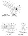
- Fig. 1 shows a plane view of a basic prior art medical laser deliverysystem of the refractive type with an obliquely cut tip;
- Fig. 2a shows a cross-section of the side fiber of the device of the presentinvention;
- Fig. 2b shows an end view of the fiber of Figure 2a;
- Fig. 3a shows a cross-section of the side fiber of the present invention witha lens formed in the quartz cap;
- Fig. 3b shows an end view of the fiber of Figure 3a;
- Fig. 4a shows a cross-section of the side fiber with a lens formed in thecap made of a highly refractive material;
- Fig. 4b shows an end view of the fiber of Figure 4a.
- The present invention involves a modified medical laser delivery devicewith sideways directed radiation that can produce high power densities at adistance further away from the fiber and thus enable non-contact ablatingprocedures to be carried out with lower laser input power levels.
- Figure 1 shows a present states of the art laser delivery system1 of therefractive type. The
laser beam 5 in theoptical fiber 2 is totally reflected downtoward theside 4 of thefiber 2 using an obliquelycut tip 3 due to the refractiveindex differences between thefiber core 6 and that of theair gap 8 formed in thecap 7. As depicted in the figure, the sidewaysirradiated beam 5 diverges in theYZ plane as it leaves thefiber 2 and passes through thetransparent quartz cap 7into the body fluids of the patient. In operation, the device1 removes unwantedtissue by a photothermic effect arising from the absorption of the laser energy bythe tissue. This effect on the tissue induced by laser radiation is stronglydependent on the power density of the laser energy at the tissue surface. If thespot size increases by merely 20%, for example, the laser power exiting the fibermust be 45% great to provide the same power density. The limitations of thepresent art and the problems which arise in its application are thus illustrated. - One embodiment of the present invention, as depicted in Figure 2a and 2b,includes the features as described in Figure 1, in addition to other elements asherein described. Thus, the
device 21 of the present invention includes anopticalfiber 22 comprising acore 26 with anoblique cut tip 23, and acap 27 attached tothefiber 22 usingglue 29 or other such substances, with anair gap 28 beingformed between thefiber 22 and thecap 27. As with the device1 of the prior art,the device of the present invention reflects alaser beam 25 out theside 24 of thefiber 22. However, in the case of the present invention, thecap 27 includes asector 30 having an optical part which intersects the exiting laser beam asdemarcated by aprofile region 31. This unique design allows sideways directed radiation that can produce high power densities at a distance further away from thefiber by focusing the exiting laser beam. - Other embodiments, the preferred embodiments, are shown with a lensplaced in the cap including that of Figures 3a and 3b. The construction andoperation of this embodiment is described in the following example, whereby an
optical fiber 42 manufactured by CeramOptec, type Optran UV 600/660, wasused. Thefiber 42 consisted of a 600 micrometer diameterpure silica core 46 witha 660 micrometer O.D. fluorinated silica cladding. with a numerical aperture of0.22. Thefiber tip 43 was exposed and cut with a prismatic angle of α = 40degrees to obtain the total side deflection of theradiation 45. A transparent quartzorpure silica cap 47 of I.D. 900 micrometers and O.D. 1800 micrometers wasused to provide anair gap 48 guaranteeing the change of refractive index to begreater than 1.6 and to protect mechanical integrity of thetip 43. A 25W CO2 laserwas coupled with a plano-convex lens of 25 cm focal length to fuse thetransparentquartz cap 47 to create theinternal curvature 50 shown in Figures 3a and 3b. Thequartz cap 47 was glued to thefiber 46 at apoint 49. Theradiation 45, reflectedfrom thecut tip 43 intersects and passes through thesector 50 of thequartz lenscap 51. - The central rays and low divergent rays from the fiber core center werefocused by the
cap lens 51. The external surface had little or no additional effecton the optics since it is basically in a water medium; and the refractive indices ofwater and quartz are very similar. By fusing thetransparent quartz glass 47 in thesector 50 into the correct profile, thelens 51 formed can collimate theoutput beam 45 and make the power density remain essentially unchanged as theprobe 41 ismoved further away the tissue surface to be treated. - Figures 4a and 4b depict another embodiment of the present inventionusing a
fiber 62 similar to that in Figure 3a and 3b and replacing thetransparentquartz cap 47 with a cap made oftransparent sapphire 67 with essentially the samedimensions as thequartz cap 47. Alens 64 is created in the area of thesector 70using a CO2 laser similarly as in the previous example within thesapphire cap 67.Thesapphire cap 67 is glued to thefiber 62 at apoint 69. Thecap 67 guaranteesboth the change in index of thefiber core 66 to air interface necessary for the lateral re-direction of the beam65 (sideways) and the optical and mechanicalintegrity of thefiber tip 63. Theoutput radiation 65 intersects with thesector 70of thesapphire lens cap - Measurements taken at the
distal tip 63, as before, determined similarresults to those obtained with thequartz lens cap equivalent lens profile 51 inquartz cap 47. This feature permits theuse of simpler geometrical profiles for thesapphire lens cap 64 than for thetransparentquartz lens cap - Another aspect of the present invention involves a method formanufacturing the device of the present invention. The plastic protective coatingsare typically removed to expose 10 to 20 mm of the fiber end, with the exposedend then being polished to the desired oblique angle, e.g. 40 degrees, as shown inthe figures. The fiber is held is a small lathe chuck by the plastic coating near thestripped section, while the quartz cap or other such cap as herein described is heldin another chuck on the lathe. The cap is placed over the exposed fiber by bringingthe chucks toward each other, Setting both chucks into synchronous rotatingmotion, a CO2 laser beam is directed at the cap in a sufficiently diffuse manner soas to heat the cap to a temperature of approximately 300 degrees C. Thetemperature can be regulated and held constant by sensing the cap's temperaturevia suitable IR sensors and controlling the laser output accordingly. A second CO2laser beam with approximately 10W of power is then directed onto the cap near itsopen end, and the cap is bonded to the fiber (circumferentially fused to the fiber),providing a much more thermally stable junction to the fiber than the gluingapproach normally employed. The spinning lathe is stopped and the diffuseradiation is discontinued. The cap, with the hot gas it contains, is allowed to cool,creating a gas pocket, then the 10W CO2 laser is directed to the sector of the capwhere the sideways deflected beam will emerge from the assembly. The glass in thesector softens and collapses toward the fiber, simultaneously spot fusing to thefiber and forming a converging lens equivalent to that shown in Figure 3. In thismanner, the cap is modified at the sector. This optical shape achieves multiplegoals: the high intensity low order modes at the center of the fiber core can passthrough the device without Fresnel reflections, while the higher order modesfurther away from the core axis are focused by the lens produced by this process.Thus, instruments such as diode lasers, which tend to have a large divergence fromtheir output end, are more efficiently focused by the device/lens of the present invention. In addition, the slightly collapsed outer cap surface resulting from thismanufacturing process creates no optical problems due to the closeness of therefractive indices of quartz, and other such materials, and the water surroundingthe cap in operation. Thus, the prismatic cut fiber and bi-directional lens allow fortotal reflection, and provide for rays to pass without Fresnel losses, respectively.
- In operation, the optical fiber is connected to a medical laser source at itsproximal end such that the distal end directs an output beam in a desired fashion.
- Having described preferred embodiments of the invention with referenceto the accompanying drawings, it is to be understood that the invention is notlimited to the precise embodiments, and that various changes and modificationsmay be effected therein by skilled in the art without departing from the scope asdefined in the appended claims.
Claims (7)
- A medical laser delivery device (21) having an optical fiber (22) terminated at a proximalend so that it can be connected to a medical laser source, with a distal end having a prismatic cutfiber tip (23) for sideways directing of an output by total reflection, said fiber's distal endenclosed by a cap (27) whose open end is bonded (29) to said fiber (22) so as to create a gaspocket (28) around said prismatic cut fiber tip (23), andcharacterized by:a sector (31) of said cap (27), lying within said output beam direction (25), beingconverted, after said cap is bonded to said fiber, into a bi-directional lens (30) for focusing orcollimating said output beam (25) as it exits said device (21) into a surrounding medium.
- A medical laser delivery device according to claim 1, wherein said bi-directional lens(51) is fused to said fiber (42) in a central area of said lens (51) to provide scatter freetransmission of said output beam (45).
- A medical laser delivery device according to claim 1, wherein said cap (21) is bonded atits open end to said fiber (22) by being circumferentially fused to said fiber.
- A method of manufacturing a medical laser delivery device comprising the steps of;cutting a prismatic tip (23) on a distal end of an optical fiber (22) so as to direct all light in saidfiber sideways to a longitudinal axis, placing a cap (27) over said distal end of said fiber,bonding said cap (27) at its open end to said fiber (22) to create a gas pocket (28) around saidprismatic fiber tip, andcharacterized by the step of:modifying a sector (31) of said cap (27) by directing a concentrated heat source at saidsector (31) and allowing it to collapse inward to form a bi-directional lens (30) which can focusor collimate an output beam (25) as it passes through said sector (31) during operation of saiddevice (21).
- A method of manufacturing according to claim 4, wherein said lens (51) is formed suchthat a central portion of said lens (51) is fused to said fiber (42).
- A method of manufacturing according to claim 5, wherein the step of bonding said cap(21) to said fiber (22) includes directing either a laser or other concentrated heating source nearsaid open end of said cap (21) and circumferentially fusing said cap (21) to said fiber's surface.
- A method of manufacturing according to claim 6, further including the step of heatingsaid cap (21) uniformly with a diffuse, controlled heat source to warm said gas pocket (28) to apredetermined temperature, before said cap (21) is circumferentially fused to said fiber's surface.
Applications Claiming Priority (2)
| Application Number | Priority Date | Filing Date | Title |
|---|---|---|---|
| US08/265,058US5509917A (en) | 1994-06-28 | 1994-06-28 | Lensed caps for radial medical laser delivery devices |
| US265058 | 1994-06-28 |
Publications (2)
| Publication Number | Publication Date |
|---|---|
| EP0689797A1 EP0689797A1 (en) | 1996-01-03 |
| EP0689797B1true EP0689797B1 (en) | 2002-02-13 |
Family
ID=23008780
Family Applications (1)
| Application Number | Title | Priority Date | Filing Date |
|---|---|---|---|
| EP95201711AExpired - LifetimeEP0689797B1 (en) | 1994-06-28 | 1995-06-23 | Lensed caps for radial medical laser delivery systems |
Country Status (3)
| Country | Link |
|---|---|
| US (1) | US5509917A (en) |
| EP (1) | EP0689797B1 (en) |
| DE (1) | DE69525392T2 (en) |
Cited By (2)
| Publication number | Priority date | Publication date | Assignee | Title |
|---|---|---|---|---|
| AU2009330031B2 (en)* | 2008-12-22 | 2012-11-29 | Ams Research Corporation | Sapphire-based delivery tip for optic fiber |
| US8582934B2 (en) | 2007-11-12 | 2013-11-12 | Lightlab Imaging, Inc. | Miniature optical elements for fiber-optic beam shaping |
Families Citing this family (86)
| Publication number | Priority date | Publication date | Assignee | Title |
|---|---|---|---|---|
| US6564087B1 (en) | 1991-04-29 | 2003-05-13 | Massachusetts Institute Of Technology | Fiber optic needle probes for optical coherence tomography imaging |
| US6485413B1 (en) | 1991-04-29 | 2002-11-26 | The General Hospital Corporation | Methods and apparatus for forward-directed optical scanning instruments |
| US6134003A (en)* | 1991-04-29 | 2000-10-17 | Massachusetts Institute Of Technology | Method and apparatus for performing optical measurements using a fiber optic imaging guidewire, catheter or endoscope |
| US6111645A (en) | 1991-04-29 | 2000-08-29 | Massachusetts Institute Of Technology | Grating based phase control optical delay line |
| DE69514262T2 (en)* | 1994-03-23 | 2001-10-11 | Hamamatsu Photonics K.K., Hamamatsu | Optical fiber catheter |
| US5921916A (en)* | 1994-07-07 | 1999-07-13 | Ueth & Haug Gmbh | Endoscope utilizing a fiber optic holding tube with a jacket slit for lateral placement of the fiber optic |
| US5772657A (en)* | 1995-04-24 | 1998-06-30 | Coherent, Inc. | Side firing fiber optic laser probe |
| US5746737A (en)* | 1995-06-07 | 1998-05-05 | Trimedyne, Inc. | Enclosure for a lasing device |
| US5833683A (en)* | 1996-01-12 | 1998-11-10 | Surgical Laser Technologies, Inc. | Laterally-emitting laser medical device |
| US5964747A (en)* | 1998-03-23 | 1999-10-12 | Duke University | Lighting instrument, in particular for use in ophthalmologic microsurgery |
| US6445939B1 (en) | 1999-08-09 | 2002-09-03 | Lightlab Imaging, Llc | Ultra-small optical probes, imaging optics, and methods for using same |
| US8256430B2 (en) | 2001-06-15 | 2012-09-04 | Monteris Medical, Inc. | Hyperthermia treatment and probe therefor |
| US6986764B2 (en)* | 2000-12-15 | 2006-01-17 | Laserscope | Method and system for photoselective vaporization of the prostate, and other tissue |
| US9440046B2 (en) | 2002-04-04 | 2016-09-13 | Angiodynamics, Inc. | Venous insufficiency treatment method |
| AUPS313802A0 (en)* | 2002-06-25 | 2002-07-18 | Riancorp Pty Ltd | Laser beam homogenisers in medical applications |
| EP2134282B1 (en)* | 2002-07-10 | 2019-05-22 | AngioDynamics, Inc. | Device for endovascular treatment for causing closure of a blood vessel |
| US8983257B2 (en)* | 2002-08-28 | 2015-03-17 | Nomir Medical Technologies, Inc. | Therapeutic light delivery apparatus, method, and system |
| US7474407B2 (en)* | 2003-02-20 | 2009-01-06 | Applied Science Innovations | Optical coherence tomography with 3d coherence scanning |
| US7909766B2 (en)* | 2003-05-21 | 2011-03-22 | Scimed Life Systems, Inc. | Systems and methods for improving the imaging resolution of an imaging transducer |
| US7909817B2 (en) | 2005-06-08 | 2011-03-22 | Innovaquartz, Inc. (AMS Research Corporation) | Lateral laser fiber for high average power and peak pulse energy |
| US11324553B2 (en)* | 2005-11-10 | 2022-05-10 | Biolitec Unternehmensbeteilgungs II AG | Side fire optical fiber for high power applications |
| DE102006016957B4 (en)* | 2006-04-11 | 2010-04-22 | Vimecon Gmbh | laser applicator |
| WO2008073263A1 (en)* | 2006-12-07 | 2008-06-19 | Ams Research Corporation | Side fire optical device for laterally redirecting high power electromagnetic energy |
| DE102007013424A1 (en)* | 2007-03-20 | 2008-09-25 | Ivoclar Vivadent Ag | light curing |
| US7507038B2 (en)* | 2007-04-03 | 2009-03-24 | Mitsubishi Cable Industries, Ltd. | Optical fiber/glass tube fusion-spliced structure, optical fiber assembly including the structure, and glass tube used in the structure |
| US20080287936A1 (en)* | 2007-05-18 | 2008-11-20 | Stinson Douglas G | Telescope with Integrated Optical Filter |
| DE102007047501A1 (en)* | 2007-10-04 | 2009-04-09 | Rolle + Rolle Gmbh + Co. Kg | Laserfokussierhandstück |
| US9149333B2 (en)* | 2008-02-28 | 2015-10-06 | Biolitec Pharma Marketing Ltd | Endoluminal laser ablation device and improved method for treating veins |
| US9693826B2 (en) | 2008-02-28 | 2017-07-04 | Biolitec Unternehmensbeteiligungs Ii Ag | Endoluminal laser ablation device and method for treating veins |
| US8425500B2 (en)* | 2008-05-19 | 2013-04-23 | Boston Scientific Scimed, Inc. | Method and apparatus for protecting capillary of laser fiber during insertion and reducing metal cap degradation |
| US9289262B2 (en)* | 2008-05-19 | 2016-03-22 | Boston Scientific Scimed, Inc. | Dielectric coatings for laser fiber and related methods |
| US20090326525A1 (en)* | 2008-06-26 | 2009-12-31 | Jessica Hixon | Laser fiber capillary apparatus and method |
| US20100049099A1 (en)* | 2008-07-18 | 2010-02-25 | Vytronus, Inc. | Method and system for positioning an energy source |
| WO2010014787A1 (en)* | 2008-07-30 | 2010-02-04 | Ams Research Corporation | Optical device having fluorocarbon polymer layer |
| US8728092B2 (en)* | 2008-08-14 | 2014-05-20 | Monteris Medical Corporation | Stereotactic drive system |
| US8747418B2 (en)* | 2008-08-15 | 2014-06-10 | Monteris Medical Corporation | Trajectory guide |
| US8899844B2 (en)* | 2008-12-01 | 2014-12-02 | Ams Research Corporation | Optical device |
| DE102008064576B4 (en)* | 2008-12-22 | 2014-10-09 | Leoni Kabel Holding Gmbh | Lateral emitting laser fiber |
| US8827991B2 (en)* | 2009-04-09 | 2014-09-09 | Biolitec Pharma Marketing Ltd | Medical laser treatment device and method utilizing total reflection induced by radiation |
| WO2011062894A2 (en)* | 2009-11-18 | 2011-05-26 | Boston Scientific Scimed, Inc. | Methods and apparatus related to a distal end of a side-fire optical fiber having multiple capillary components |
| EP2501318B1 (en)* | 2009-11-18 | 2020-08-26 | Boston Scientific Scimed, Inc. | Methods and apparatus related to a side -fire member having a doped silica component |
| US8724941B2 (en)* | 2010-02-22 | 2014-05-13 | Boston Scientific Scimed, Inc. | Methods and apparatus related to a side-fire optical fiber having a robust distal end portion |
| US8672929B2 (en) | 2010-12-15 | 2014-03-18 | Ams Research Corporation | Laser probe tip |
| EP2677961B1 (en) | 2011-02-24 | 2024-12-11 | Eximo Medical Ltd. | Hybrid catheter for vascular intervention |
| DE102011016852A1 (en) | 2011-04-06 | 2012-10-11 | Laser- Und Medizin-Technologie Gmbh, Berlin | Device for detecting light in cavities or lumens in medical catheters, has light waves leading fiber whose end portion is formed as concave mirror at predetermined angle with respect to longitudinal axis |
| US8992513B2 (en) | 2011-06-30 | 2015-03-31 | Angiodynamics, Inc | Endovascular plasma treatment device and method of use |
| EP2866723A4 (en) | 2012-06-27 | 2016-12-14 | Monteris Medical Corp | GUIDED THERAPY BY IMAGE OF A FABRIC |
| US20140107630A1 (en)* | 2012-09-27 | 2014-04-17 | Trimedyne, Inc. | Side firing optical fiber device for consistent, rapid vaporization of tissue and extended longevity |
| US20140126876A1 (en)* | 2012-11-05 | 2014-05-08 | Ofs Fitel, Llc | Cap for optical fiber |
| US10675113B2 (en) | 2014-03-18 | 2020-06-09 | Monteris Medical Corporation | Automated therapy of a three-dimensional tissue region |
| US9433383B2 (en) | 2014-03-18 | 2016-09-06 | Monteris Medical Corporation | Image-guided therapy of a tissue |
| US20150265353A1 (en) | 2014-03-18 | 2015-09-24 | Monteris Medical Corporation | Image-guided therapy of a tissue |
| US9488782B2 (en) | 2014-12-22 | 2016-11-08 | InnovaQuartz LLC | Redirecting electromagnetic radiation |
| US9323005B1 (en) | 2014-12-22 | 2016-04-26 | InnovaQuartz LLC | Redirecting electromagnetic radiation |
| US10327830B2 (en) | 2015-04-01 | 2019-06-25 | Monteris Medical Corporation | Cryotherapy, thermal therapy, temperature modulation therapy, and probe apparatus therefor |
| KR101763637B1 (en) | 2015-08-25 | 2017-08-03 | 부경대학교 산학협력단 | Optical fiber, apparatus and method cutting of fiber tips for total internal reflection with a controlled laser |
| US11826097B2 (en) | 2015-11-18 | 2023-11-28 | Cyclone Biosciences, Llc | Forming radial emissions from optical fibers |
| US10092356B2 (en) | 2015-11-18 | 2018-10-09 | InnovaQuartz LLC | Radial emissions from optical fibers |
| US9618700B1 (en) | 2015-12-03 | 2017-04-11 | InnovaQuartz LLC | Orthogonal output optical fiber |
| US9662173B1 (en) | 2015-12-24 | 2017-05-30 | Cyclone Biosciences LLC | Lateral delivery device with active cooling |
| CN109414292A (en) | 2016-05-05 | 2019-03-01 | 爱克斯莫医疗有限公司 | Device and method for cutting off and/or melting unwanted tissue |
| US10405923B2 (en) | 2016-08-12 | 2019-09-10 | Boston Scientific Scimed, Inc. | Systems, devices, and related methods for laser lithotripsy |
| WO2019010113A1 (en) | 2017-07-06 | 2019-01-10 | Boston Scientific Scimed, Inc. | Optical fibers and associated systems |
| US10806329B2 (en)* | 2018-01-24 | 2020-10-20 | Canon U.S.A., Inc. | Optical probes with optical-correction components |
| US10816789B2 (en) | 2018-01-24 | 2020-10-27 | Canon U.S.A., Inc. | Optical probes that include optical-correction components for astigmatism correction |
| US11819229B2 (en) | 2019-06-19 | 2023-11-21 | Boston Scientific Scimed, Inc. | Balloon surface photoacoustic pressure wave generation to disrupt vascular lesions |
| US12402946B2 (en) | 2019-06-19 | 2025-09-02 | Boston Scientific Scimed, Inc. | Breakdown of laser pulse energy for breakup of vascular calcium |
| US11717139B2 (en) | 2019-06-19 | 2023-08-08 | Bolt Medical, Inc. | Plasma creation via nonaqueous optical breakdown of laser pulse energy for breakup of vascular calcium |
| US11660427B2 (en) | 2019-06-24 | 2023-05-30 | Boston Scientific Scimed, Inc. | Superheating system for inertial impulse generation to disrupt vascular lesions |
| US12280223B2 (en) | 2019-06-26 | 2025-04-22 | Boston Scientific Scimed, Inc. | Focusing element for plasma system to disrupt vascular lesions |
| US12102384B2 (en) | 2019-11-13 | 2024-10-01 | Bolt Medical, Inc. | Dynamic intravascular lithotripsy device with movable energy guide |
| US12274497B2 (en) | 2019-12-18 | 2025-04-15 | Bolt Medical, Inc. | Multiplexer for laser-driven intravascular lithotripsy device |
| US11672599B2 (en) | 2020-03-09 | 2023-06-13 | Bolt Medical, Inc. | Acoustic performance monitoring system and method within intravascular lithotripsy device |
| US20210290286A1 (en) | 2020-03-18 | 2021-09-23 | Bolt Medical, Inc. | Optical analyzer assembly and method for intravascular lithotripsy device |
| US11707323B2 (en) | 2020-04-03 | 2023-07-25 | Bolt Medical, Inc. | Electrical analyzer assembly for intravascular lithotripsy device |
| US12295654B2 (en) | 2020-06-03 | 2025-05-13 | Boston Scientific Scimed, Inc. | System and method for maintaining balloon integrity within intravascular lithotripsy device with plasma generator |
| US12207870B2 (en) | 2020-06-15 | 2025-01-28 | Boston Scientific Scimed, Inc. | Spectroscopic tissue identification for balloon intravascular lithotripsy guidance |
| US12376904B1 (en) | 2020-09-08 | 2025-08-05 | Angiodynamics, Inc. | Dynamic laser stabilization and calibration system |
| US12016610B2 (en) | 2020-12-11 | 2024-06-25 | Bolt Medical, Inc. | Catheter system for valvuloplasty procedure |
| EP4277548B1 (en) | 2021-01-12 | 2025-06-04 | Bolt Medical, Inc. | Balloon assembly for valvuloplasty catheter system |
| US11672585B2 (en) | 2021-01-12 | 2023-06-13 | Bolt Medical, Inc. | Balloon assembly for valvuloplasty catheter system |
| DE102021102091A1 (en) | 2021-01-29 | 2022-08-04 | Leibniz-Institut für Photonische Technologien e.V. (Engl.Leibniz Institute of Photonic Technology) | Multimode optical fiber, endoscopic system and method for examining a sample |
| US11648057B2 (en) | 2021-05-10 | 2023-05-16 | Bolt Medical, Inc. | Optical analyzer assembly with safety shutdown system for intravascular lithotripsy device |
| US11806075B2 (en) | 2021-06-07 | 2023-11-07 | Bolt Medical, Inc. | Active alignment system and method for laser optical coupling |
| US11839391B2 (en) | 2021-12-14 | 2023-12-12 | Bolt Medical, Inc. | Optical emitter housing assembly for intravascular lithotripsy device |
| US12038322B2 (en) | 2022-06-21 | 2024-07-16 | Eximo Medical Ltd. | Devices and methods for testing ablation systems |
Family Cites Families (17)
| Publication number | Priority date | Publication date | Assignee | Title |
|---|---|---|---|---|
| GB778276A (en)* | 1954-10-21 | 1957-07-03 | Richard Wolf | Improvements in or relating to endoscopes |
| US4778247A (en)* | 1984-05-04 | 1988-10-18 | Warner Lambert Technologies, Inc. | Molded objective head for fiberscopes with integral lenses |
| US5167686A (en)* | 1985-03-06 | 1992-12-01 | C. R. Bard, Inc. | Catheter system for controlled removal by radiant energy of biological obstructions |
| US4669467A (en)* | 1985-03-22 | 1987-06-02 | Massachusetts Institute Of Technology | Mode mixer for a laser catheter |
| US4718417A (en)* | 1985-03-22 | 1988-01-12 | Massachusetts Institute Of Technology | Visible fluorescence spectral diagnostic for laser angiosurgery |
| JP2615006B2 (en)* | 1985-03-26 | 1997-05-28 | 富士写真光機 株式会社 | Laser beam side fiber |
| FR2597744A1 (en)* | 1986-04-29 | 1987-10-30 | Boussignac Georges | CARDIO-VASCULAR CATHETER FOR LASER SHOOTING |
| JPH0531613Y2 (en)* | 1986-05-14 | 1993-08-13 | ||
| US4672961A (en)* | 1986-05-19 | 1987-06-16 | Davies David H | Retrolasing catheter and method |
| US4860743A (en)* | 1986-10-27 | 1989-08-29 | University Of Florida | Laser method and apparatus for the recanalization of vessels and the treatment of other cardiac conditions |
| DE3878485D1 (en)* | 1987-05-25 | 1993-03-25 | Deutsche Aerospace | DEVICE FOR CIRCUMFERENTIAL RADIATION OF OBJECTS. |
| US4770653A (en)* | 1987-06-25 | 1988-09-13 | Medilase, Inc. | Laser angioplasty |
| US4842350A (en)* | 1988-04-18 | 1989-06-27 | Collings James A | Bar unit |
| US5061265A (en)* | 1989-06-20 | 1991-10-29 | University Of Florida | Laser treatment apparatus and method |
| US5163935A (en)* | 1991-02-20 | 1992-11-17 | Reliant Laser Corporation | Surgical laser endoscopic focusing guide with an optical fiber link |
| US5292320A (en)* | 1992-07-06 | 1994-03-08 | Ceramoptec, Inc. | Radial medical laser delivery device |
| US5342355A (en)* | 1992-10-19 | 1994-08-30 | Laser Centers Of America | Energy delivering cap element for end of optic fiber conveying laser energy |
- 1994
- 1994-06-28USUS08/265,058patent/US5509917A/ennot_activeExpired - Fee Related
- 1995
- 1995-06-23DEDE69525392Tpatent/DE69525392T2/ennot_activeExpired - Fee Related
- 1995-06-23EPEP95201711Apatent/EP0689797B1/ennot_activeExpired - Lifetime
Cited By (4)
| Publication number | Priority date | Publication date | Assignee | Title |
|---|---|---|---|---|
| US8582934B2 (en) | 2007-11-12 | 2013-11-12 | Lightlab Imaging, Inc. | Miniature optical elements for fiber-optic beam shaping |
| US9091524B2 (en) | 2007-11-12 | 2015-07-28 | Lightlab Imaging, Inc. | Miniature optical elements for fiber-optic beam shaping |
| US9404731B2 (en) | 2007-11-12 | 2016-08-02 | Lightlab Imaging, Inc. | Miniature optical elements for fiber-optic beam shaping |
| AU2009330031B2 (en)* | 2008-12-22 | 2012-11-29 | Ams Research Corporation | Sapphire-based delivery tip for optic fiber |
Also Published As
| Publication number | Publication date |
|---|---|
| US5509917A (en) | 1996-04-23 |
| DE69525392D1 (en) | 2002-03-21 |
| EP0689797A1 (en) | 1996-01-03 |
| DE69525392T2 (en) | 2002-10-24 |
Similar Documents
| Publication | Publication Date | Title |
|---|---|---|
| EP0689797B1 (en) | Lensed caps for radial medical laser delivery systems | |
| US10993768B2 (en) | Radial emissions from optical fibers | |
| US5537499A (en) | Side-firing laser optical fiber probe and method of making same | |
| US5562657A (en) | Side fire laser catheter method and apparatus | |
| US5707368A (en) | Contact tip for laser surgery | |
| EP0566873B1 (en) | Two-piece tip for fiber optic catheter | |
| US4676586A (en) | Apparatus and method for performing laser material processing through a fiber optic | |
| US5163935A (en) | Surgical laser endoscopic focusing guide with an optical fiber link | |
| KR0155393B1 (en) | Microlenses for coupling optical fibers to elliptical light beams | |
| US5571099A (en) | Side firing probe | |
| US5359685A (en) | Focusing tips for optical fibers | |
| EP0598984A1 (en) | Radial medical laser delivery device | |
| US20090092359A1 (en) | Side-firing laser | |
| US5688263A (en) | Laser surgery applicator | |
| US11998269B2 (en) | Forming radial emissions from optical fibers | |
| WO2008016455A2 (en) | Bent side-firing laser | |
| US9618700B1 (en) | Orthogonal output optical fiber | |
| KR19990087970A (en) | Laser handpiece | |
| EP1189545A1 (en) | Cutting blade for surgical instrument | |
| JPH02271853A (en) | Flexible guide for light energy | |
| GB2154017A (en) | Laser material processing through a fiber optic | |
| US20240390066A1 (en) | Optical fiber device and method for thermal therapy and laser thermal ablation treatments | |
| GB2219213A (en) | A method of making a catheter | |
| Guth | CO2 Laser Fabrication of Optical Surfaces on Fiber Optic Devices | |
| GB2291214A (en) | Light delivery using fibre optics with ellipsoidal contact probe |
Legal Events
| Date | Code | Title | Description |
|---|---|---|---|
| PUAI | Public reference made under article 153(3) epc to a published international application that has entered the european phase | Free format text:ORIGINAL CODE: 0009012 | |
| AK | Designated contracting states | Kind code of ref document:A1 Designated state(s):DE GB | |
| 17P | Request for examination filed | Effective date:19960627 | |
| 17Q | First examination report despatched | Effective date:19990120 | |
| GRAG | Despatch of communication of intention to grant | Free format text:ORIGINAL CODE: EPIDOS AGRA | |
| GRAG | Despatch of communication of intention to grant | Free format text:ORIGINAL CODE: EPIDOS AGRA | |
| GRAG | Despatch of communication of intention to grant | Free format text:ORIGINAL CODE: EPIDOS AGRA | |
| GRAH | Despatch of communication of intention to grant a patent | Free format text:ORIGINAL CODE: EPIDOS IGRA | |
| GRAH | Despatch of communication of intention to grant a patent | Free format text:ORIGINAL CODE: EPIDOS IGRA | |
| GRAA | (expected) grant | Free format text:ORIGINAL CODE: 0009210 | |
| REG | Reference to a national code | Ref country code:GB Ref legal event code:IF02 | |
| RIC1 | Information provided on ipc code assigned before grant | Free format text:7A 61B 18/00 A, 7A 61B 18/20 B | |
| AK | Designated contracting states | Kind code of ref document:B1 Designated state(s):DE GB | |
| REF | Corresponds to: | Ref document number:69525392 Country of ref document:DE Date of ref document:20020321 | |
| PLBE | No opposition filed within time limit | Free format text:ORIGINAL CODE: 0009261 | |
| STAA | Information on the status of an ep patent application or granted ep patent | Free format text:STATUS: NO OPPOSITION FILED WITHIN TIME LIMIT | |
| 26N | No opposition filed | Effective date:20021114 | |
| PGFP | Annual fee paid to national office [announced via postgrant information from national office to epo] | Ref country code:GB Payment date:20050613 Year of fee payment:11 | |
| PGFP | Annual fee paid to national office [announced via postgrant information from national office to epo] | Ref country code:DE Payment date:20050824 Year of fee payment:11 | |
| PG25 | Lapsed in a contracting state [announced via postgrant information from national office to epo] | Ref country code:GB Free format text:LAPSE BECAUSE OF NON-PAYMENT OF DUE FEES Effective date:20060623 | |
| PG25 | Lapsed in a contracting state [announced via postgrant information from national office to epo] | Ref country code:DE Free format text:LAPSE BECAUSE OF NON-PAYMENT OF DUE FEES Effective date:20070103 | |
| GBPC | Gb: european patent ceased through non-payment of renewal fee | Effective date:20060623 |