EP0687400B1 - An optoelectric transducer - Google Patents
An optoelectric transducerDownload PDFInfo
- Publication number
- EP0687400B1 EP0687400B1EP94906334AEP94906334AEP0687400B1EP 0687400 B1EP0687400 B1EP 0687400B1EP 94906334 AEP94906334 AEP 94906334AEP 94906334 AEP94906334 AEP 94906334AEP 0687400 B1EP0687400 B1EP 0687400B1
- Authority
- EP
- European Patent Office
- Prior art keywords
- transducer
- photodiode
- photodetector
- optical
- radio
- Prior art date
- Legal status (The legal status is an assumption and is not a legal conclusion. Google has not performed a legal analysis and makes no representation as to the accuracy of the status listed.)
- Expired - Lifetime
Links
Images


Classifications
- H—ELECTRICITY
- H04—ELECTRIC COMMUNICATION TECHNIQUE
- H04B—TRANSMISSION
- H04B10/00—Transmission systems employing electromagnetic waves other than radio-waves, e.g. infrared, visible or ultraviolet light, or employing corpuscular radiation, e.g. quantum communication
- H04B10/29—Repeaters
- H—ELECTRICITY
- H04—ELECTRIC COMMUNICATION TECHNIQUE
- H04B—TRANSMISSION
- H04B10/00—Transmission systems employing electromagnetic waves other than radio-waves, e.g. infrared, visible or ultraviolet light, or employing corpuscular radiation, e.g. quantum communication
- H04B10/25—Arrangements specific to fibre transmission
- H04B10/2575—Radio-over-fibre, e.g. radio frequency signal modulated onto an optical carrier
- H04B10/25752—Optical arrangements for wireless networks
Definitions
- the present inventionrelates to a transducer, and in particular to a transducer suitable for use in a hybrid optical and radio communications system.
- Hybrid optical and radio communications systemsare expected to find an increasing role in telecoms networks over the next decade due to their ability to combine the flexible and low cost distribution afforded by optical transmission with 'wireless' radio transmission in areas such as personal mobility or antenna remoting.
- Optical fibre and millimetre-wave radioare both capable of supporting the large bandwidth requirements associated with these services.
- Running fibre direct to the home or businessis one way of providing high capacity, but for operational reasons this is not always an appropriate solution.
- millimetre-wave radio systemssuch as the RACE Mobile Broadband system or radio LANs, are flexible and offer the advantage of expedient provision. It is likely, therefore, that a hybrid network comprising both radio and fibre will play a significant role in early broadband local-access systems.
- the paper of Wake et aldiscloses a radio-fibre communications system comprising a source of optical fibres at a first site, a transducer at a second site, a receiving radio antenna at a third site, and an optical fibre coupled at a first end to the optical signal source and at a second end to the transducer, so that signals generated at the first site are transmitted optically to the second site via the optical fibre, converted at the second site by the transducer from optical signals to radio signals and transmitted as radio signals to the tird site where they are received by said receiving antenna.
- An object of the present inventionis to provide an improved transducer for use in hybrid optical and radio communications systems.
- a transducerfor use in a hybrid optical and radio communications system, the transducer comprising:- a photodetector and a radio antenna; the photodetector being directly electrically connected to the radio antenna so that in use optical signals are received and radio signals are transmitted by the transducer characterised in that the photodetector is a zero electrical power photodetector; and the optical signals are received and the radio signals are transmitted by the transducer without the use of electrical power.
- the present inventionis based on the applicant's realisation that a zero electrical power photodetector can surprisingly be directly electrically connected to a radio antenna to give a transducer which operates with no electrical power supply.
- a transducer according to the present inventioncan be remotely sited for example in the local access network at a site having no electrical power supply, for example at the top of a telegraph pole serving a number of customers in a particular street.
- the optical signals arriving at the transducer from a central sitefor example via an optical fibre, are converted to electrical signals and retransmitted as radio signals via the radio antenna, without the use of externally supplied electrical power.
- the radio signalsare subsequently received at a third site, for example the customer's premises, and are there demodulated.
- a transducer according to the present inventioncan thus be remotely sited at locations not having an electrical power supply. Furthermore the design of the transducer is considerably simplified allowing for example a simple fibre-in antenna-out arrangement.
- the prior art transducercomprising an electrically powered photodetector formed from a monolithically integrated optical preamplifier and photodiode, described by Wake et al in the above referenced paper, can thus be replaced by a transducer according to the present invention to allow more flexible remote siting.
- the zero electrical power photodetectorcomprises a zero-bias photodiode.
- Photodiodesrequire an electric field between their contacts which is sufficient to cause photogenerated carriers to drift to the contacts with saturated velocity.
- Zero-bias photodiodesare designed so that an adequate internal electric field is generated by using only the built-in junction potential, so that an external biasing voltage is not required, thus enabling their operation without the provision of electrical power to them.
- Such zero-bias photodiodesare known for example from Wake, D., Spooner, T. P., Perrin, S. D., and Henning, I.D.: ' 50GHz InGaAs edge-coupled pin photodetector', Electron. Lett., 27, 1991, pp1073-1074 and J.E. Bowers, C.A. Burrus, High-speed zero-bias waveguide photodetectors, Electron. Lett., vol.22, No.17, 14. 8. 86.
- the zero-bias photodiodeis an edge-coupled PIN photodiode.
- These two conflicting aimscan be meet since the absorber layer in an edge-coupled photodiode can be thin enough to give a short carrier transit distance, while being long enough to have little effect on the internal quantum efficiency.
- the transducercomprises a contact layer provided to facilitate ohmic contact to the photodiode. Provision of a contact layer is important for a zero-bias photodiode since if the electrical contacts made to the photodiode are not ohmic, i.e. if they create a contact potential. then such a potential will oppose the effect of the internal junction potential and may render the zero-bias photodiode inoperative.
- the absorber layeris less than 0.5 ⁇ m thick, more preferably less than 0. 2 ⁇ m thick, still more preferably less than 0.15 ⁇ m thick, and most preferably substantially 0.13 ⁇ m thick.
- a particularly thin absorber layerallows an adequate internal electrical field to be generated from the junction potential alone, obviating the need for external biasing of the photodiode.
- the zero electrical power photodetectorcan comprise a self-biasing photodetector.
- a self-biasing photodetectoremploys part of the input optical power to the transducer to provide an electrical bias for the photodetector.
- a transduceris provided having only an optical input and a radio output, with no electrical power supplied.
- the self-biasing photodetectorcomprises a first biased photodiode
- the self-biasing photodetectoremploys some of the incident optical power to bias the first photodiode, and thus has a higher output power saturation than the zero-bias arrangement, because the first photodiode may be optimally biased.
- the photocurrent generated in each of the first and second photodiodesis substantially the same for optimum operation of the self-biasing photodetector.
- the first biased photodiode of the self-biasing photodetectorcomprises a low capacitance, high-speed photodiode and the second biasing photodiode comprises a high capacitance low speed photodiode, so that the electrical output of the second biasing photodiode is substantially unaffected by modulation of the input optical signals, and the electrical output of the first biased photodiode closely follows modulation of the input optical signals.
- This arrangementenables the second photodiode to provide a substantially DC, optimised bias current to the first photodiode which has been specifically designed for high speed, high responsivity operation.
- the optical distribution means of the self-bias photodetectoris wavelength selective, for example comprising a wavelength selective fused tapered coupler.
- a transducercan be employed in a communications system in which optical signals are supplied to the transducer at two different wavelengths, the signals at a first wavelength being modulated to carry information and being directed to the first photodiode by the wavelength selective optical distribution means, and the signals at a second wavelength being unmodulated and being directed to the second photodiode.
- This arrangementhas the advantage that the responsivity of the self-biasing photodetector in relation to the information carrying input optical power is not reduced, relative to the zero-bias arrangement, since none of the information carrying optical input power is employed to bias the first photodiode.
- the first and second photodiodes of the self biasing photodetectorare monolithically integrated to give a compact design.
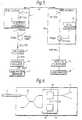
- Figure 1shows a transducer comprising a zero-bias edge-coupled high speed photodiode 2, directly electrically connected to a standard gain horn antenna 3.
- Optical signalsare input to the transducer via single mode optical fibre 4 having a standard 12 ⁇ m radius lens 5.
- Photodiode 2is of the type described in Wake, D., Spooner, T.P., Perrin, S.D., and Henning, I.D.: '50GHz InGaAs edge-coupled pin photodetector', Electron. Lett., 27, 1991, pp1073-1074, the disclosure of which is hereby incorporated within the present application by reference.
- the photodiode 2comprises an InGaAs absorber layer 6 having a length of 10 ⁇ m, a width of 5 ⁇ m, and a thickness of 0.13 ⁇ m.
- the structureis grown by MOVPE on a sulphur-doped InP substrate 7 and mesa etching is used to define the grown-in p-n junction.
- a 4 ⁇ m thick dielectric layer 8(polyimide) is used to reduce bondpad capacitance.
- a contact layer 23is thus included to reduce any potential barrier at the p-side contact 24.
- This contact layer 23consists of highly p-doped I nGaAs (N a >1E19cm -3 ), and has a thickness of 0.1 ⁇ m.
- the photodiode 2is then mounted on a package incorporating a Wilton K-connector to allow characterisation up to a frequency of 40 GHz. Although leakage current is not an important parameter for zero bias operation, values less than 1nA at -2V are typical. An external quantum efficiency of 46% was measured for the photodiode 2 at a wavelength of 1556nm,.
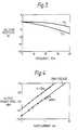
- Measurement of the frequency responsewas performed using an optical heterodyne technique, in which the beat frequency was swept by current tuning one of a pair of DFB lasers at a wavelength around 1556nm, and the electrical output power from the photodiode was measured using a broadband power sensor.
- the frequency responseis shown in Figure 3 for bias voltages of 0V and -2V and with optical power set to give a photocurrent of 0.1mA.
- the photodiode 2had a 3dB bandwidth of 37 GHz at a bias of -2V, and the penalty incurred for zero bias operation ranged from less than 0.5dB at 0.1 GHz to 4dB at 40 GHz.
- the transducer 1was used in a radio-fibre communications system shown in Figure 5.
- a three-contact DFB laser 9, optimised for high FM responseis driven by a 4.1 GHz microwave oscillator 10.
- the resulting optical FMwas converted to IM at harmonics of the drive frequency by phase perturbation of the optical FM sidebands resulting from the dispersion caused by 12.5km of step index fibre 11.
- This techniqueresults in a mm-wave carrier signal of spectral purity determined by that of the microwave oscillator 10, which in this case had subHz linewidth.
- Modulationis applied by connecting a video signal from a video pattern generator 12 to the FM input of the microwave oscillator 10.
- the resulting optical signalwas detected by the zero-bias edge-coupled photodiode 2 of the transducer 1, and then retransmitted as a radio signal via the standard gain horn antenna 3. No electrical power was supplied to the transducer 1.
- the 7th harmonic (at 28.7 GHz) of the drive signalwas selected using a radio receiver 13 having a local oscillator 14 operating at a frequency of 27.61 Ghz.
- the resulting IF(at 1090MHz) was demodulated using a satellite TV receiver 15, and displayed on a monitor 16. The high quality of the displayed image adequately demonstrated the success of zero electrical power transducer transmission.
- Figure 6shows a second embodiment of the present invention comprising a transducer 1 having a self-biasing photodetector 17 formed from a high speed, low capacitance photodiode 18, directly electrically connected to a standard gain horn antenna 3, and a low speed, high capacitance photodiode 19, and optical distribution means comprising a 3dB fused tapered coupler 20.
- optical signals input to the transducer 1 via the optical fibre 4are distributed to both the high speed photodiode 18 and the low speed photodiode 19 by the coupler 20.
- the optical signals impinging on low speed photodiode 19generate a photocurrent which is directed by electrical connection 22 to high speed photodiode 18.
- Electrical connection 22serves to connect photodiodes 18 and 19 in parallel, so that the anode of one is connected to the cathode of the other, and vice versa. Because of the high capacitance of photodiode 19 the photocurrent generated therein is substantially a DC current.
- the quantum efficiencies of the photodiodes 18 and 19are arranged to be substantially equal so that given equal distribution of the optical input power between the photodiodes 18, 19 by the optical distribution means 20, substantially equal photocurrents are generated in photodiodes 18 and 19.
- Figure 7shows a monlithically integrated self-biasing photodetector comprising two edge-coupled PIN photodiodes grown one on top of the other.
- the lower photodiodehas a larger area absorber layer 6 and thus forms the high capacitance, low speed biasing photodiode 19, while the upper photodiode has a smaller area absorber layer 6 and forms the low capacitance, high speed photodiode 18.
- the zero-bias photodiode of the inventionmay comprise any photodiode having a built in electric field, for example a Schottky photodiode or a metal-semiconductor - metal photodiode.
- the self-biasing photo-detector of the secord embodiment of the inventioncould comprise a photo-conductor or phototransistor in place of the biased photodiode.
Landscapes
- Physics & Mathematics (AREA)
- Electromagnetism (AREA)
- Engineering & Computer Science (AREA)
- Computer Networks & Wireless Communication (AREA)
- Signal Processing (AREA)
- Optical Communication System (AREA)
- Light Receiving Elements (AREA)
- Photovoltaic Devices (AREA)
Abstract
Description
Claims (17)
- A transducer for use in a hybrid optical and radio communications system,the transducer comprising:-a photodetector (2) and a radio antenna (3);the photodetector (2) being directly electrically connected to the radioantenna (3) so that in use optical signals are received and radio signals aretransmitted by the transducer characterised in thatthe photodetector is a zero electrical power photodetector; andthe optical signals are received and the radio signals are transmitted by thetransducer without the use of electrical power.
- A transducer as claimed in claim 1, wherein the photodetector (2)comprises a zero-bias photodiode.
- A transducer as claimed in claim 2, wherein the zero-bias photodiode is anedge-coupled PIN photodiode.
- A transducer as claimed in claim 2 or claim 3, comprising a contact layer(23) provided to facilitate ohmic contact to the photodiode.
- A transducer as claimed in claim 4, wherein the contact layer (23) isformed of highly p-doped indium gallium arsenide.
- A transducer as claimed in any one of claim 3, 4 or 5 wherein the absorberlayer (6) of the photodiode is less than 0.5 µm thick.
- A transducer as claimed in claim 6, wherein the absorber layer (6) issubstantially 0.13 µm thick.
- A transducer as claimed in claim 6 or claim 7 , wherein the absorber layer(6) is formed of indium gallium arsenide.
- A transducer as claimed in claim 1, wherein the photodetector (2)comprises a self-biasing photodetector (17), which, in use, utilises a part of theinput optical power to the transducer to provide an electrical bias to thephotodetector.
- A transducer as claimed in claim 9, wherein the self-biasing photodetectorcomprises:a first biased photodiode (18),a second biasing photodiode (19) in electrical contact with the firstphotodiode (18),and optical distribution means (20),the arrangement being such that in use the optical distribution means (20)distribute optical signals, input to the transducer, to illuminate both photodiodes,and the photogenerated current of the second biasing photodiode is directed tobias the first biased photodiode.
- A transducer as claimed in claim 10, wherein the photocurrent generatedin each of the first and second photodiodes (18, 19) is substantially the same.
- A transducer as claimed in claim 10 or claim 11, wherein the first biasedphotodiode (18) comprises a low capacitance, high-speed photodiode and thesecond biasing photodiode (19) comprises a high capacitance low speedphotodiode, so that the electrical output of the second biasing photodiode issubstantially unaffected by modulation of the input optical signals, and theelectrical output of the first biased photodiode closely follows modulation of theinput optical signals.
- A transducer as claimed in claim 12, wherein the capacitance of the firstphotodiode (18) is less than 0.2pF, and the capacitance of the second photodiode(19) is greater than 1 pF.
- A transducer as claimed in any one of claim 10 to claim 13, wherein theoptical distribution means (20) is wavelength selective.
- A transducer as claimed in any one of claim 10 to claim 14, wherein thefirst and second photodiodes (18, 19) are monolithically integrated.
- A radio-fibre communications system comprising a source of opticalsignals at a first site, a transducer (2) at a second site, the transducer comprising aphotodetector (2) directly electricaly connected to a radio antenna (3), so that inuse optical signals are received and radio signals are transmitted by the transducer,a receiving radio antenna at a third site, and an optical fibre (4) coupled at a firstend to the optical signal source and at a second end to the transducer, so thatsignals generated at the first site are transmitted optically to the second site viathe optical fibre (4), converted at the second site by the transducer (2) from opticalsignals to radio signals and transmitted as radio signals to the third site where theyare received by said receiving radio antenna, characterised in that the transducer isas claimed in any one of the preceding claims.
- A method of transducing optical signals to radio signals in a hybrid opticaland radio communications system, the method comprising:connecting a photodetector (2, 17) directly to a radio antenna (3), andpassing optical signals to said photodetector to transmit corresponding radiosignals from the antenna, characterised in that;the photodetector (2, 17) is a zero electrical power photodetector; andthe corresponding radio signals are transmitted from the antenna (3)without the use of an electrical power supply.
Priority Applications (1)
| Application Number | Priority Date | Filing Date | Title |
|---|---|---|---|
| EP94906334AEP0687400B1 (en) | 1993-03-01 | 1994-02-16 | An optoelectric transducer |
Applications Claiming Priority (4)
| Application Number | Priority Date | Filing Date | Title |
|---|---|---|---|
| EP93301563 | 1993-03-01 | ||
| EP93301563 | 1993-03-01 | ||
| PCT/GB1994/000310WO1994021060A1 (en) | 1993-03-01 | 1994-02-16 | An optoelectric transducer |
| EP94906334AEP0687400B1 (en) | 1993-03-01 | 1994-02-16 | An optoelectric transducer |
Publications (2)
| Publication Number | Publication Date |
|---|---|
| EP0687400A1 EP0687400A1 (en) | 1995-12-20 |
| EP0687400B1true EP0687400B1 (en) | 1998-11-11 |
Family
ID=8214328
Family Applications (1)
| Application Number | Title | Priority Date | Filing Date |
|---|---|---|---|
| EP94906334AExpired - LifetimeEP0687400B1 (en) | 1993-03-01 | 1994-02-16 | An optoelectric transducer |
Country Status (10)
| Country | Link |
|---|---|
| US (1) | US5949564A (en) |
| EP (1) | EP0687400B1 (en) |
| JP (1) | JP3597531B2 (en) |
| KR (1) | KR960701529A (en) |
| AU (1) | AU686133B2 (en) |
| CA (1) | CA2156429C (en) |
| DE (1) | DE69414555T2 (en) |
| DK (1) | DK0687400T3 (en) |
| ES (1) | ES2126096T3 (en) |
| WO (1) | WO1994021060A1 (en) |
Cited By (51)
| Publication number | Priority date | Publication date | Assignee | Title |
|---|---|---|---|---|
| US7590354B2 (en) | 2006-06-16 | 2009-09-15 | Corning Cable Systems Llc | Redundant transponder array for a radio-over-fiber optical fiber cable |
| US7627250B2 (en) | 2006-08-16 | 2009-12-01 | Corning Cable Systems Llc | Radio-over-fiber transponder with a dual-band patch antenna system |
| US7787823B2 (en) | 2006-09-15 | 2010-08-31 | Corning Cable Systems Llc | Radio-over-fiber (RoF) optical fiber cable system with transponder diversity and RoF wireless picocellular system using same |
| US7848654B2 (en) | 2006-09-28 | 2010-12-07 | Corning Cable Systems Llc | Radio-over-fiber (RoF) wireless picocellular system with combined picocells |
| US8111998B2 (en) | 2007-02-06 | 2012-02-07 | Corning Cable Systems Llc | Transponder systems and methods for radio-over-fiber (RoF) wireless picocellular systems |
| US8175459B2 (en) | 2007-10-12 | 2012-05-08 | Corning Cable Systems Llc | Hybrid wireless/wired RoF transponder and hybrid RoF communication system using same |
| US8275265B2 (en) | 2010-02-15 | 2012-09-25 | Corning Cable Systems Llc | Dynamic cell bonding (DCB) for radio-over-fiber (RoF)-based networks and communication systems and related methods |
| US8548330B2 (en) | 2009-07-31 | 2013-10-01 | Corning Cable Systems Llc | Sectorization in distributed antenna systems, and related components and methods |
| US8644844B2 (en) | 2007-12-20 | 2014-02-04 | Corning Mobileaccess Ltd. | Extending outdoor location based services and applications into enclosed areas |
| US8867919B2 (en) | 2007-07-24 | 2014-10-21 | Corning Cable Systems Llc | Multi-port accumulator for radio-over-fiber (RoF) wireless picocellular systems |
| US8873585B2 (en) | 2006-12-19 | 2014-10-28 | Corning Optical Communications Wireless Ltd | Distributed antenna system for MIMO technologies |
| US9037143B2 (en) | 2010-08-16 | 2015-05-19 | Corning Optical Communications LLC | Remote antenna clusters and related systems, components, and methods supporting digital data signal propagation between remote antenna units |
| US9042732B2 (en) | 2010-05-02 | 2015-05-26 | Corning Optical Communications LLC | Providing digital data services in optical fiber-based distributed radio frequency (RF) communication systems, and related components and methods |
| US9112611B2 (en) | 2009-02-03 | 2015-08-18 | Corning Optical Communications LLC | Optical fiber-based distributed antenna systems, components, and related methods for calibration thereof |
| US9178635B2 (en) | 2014-01-03 | 2015-11-03 | Corning Optical Communications Wireless Ltd | Separation of communication signal sub-bands in distributed antenna systems (DASs) to reduce interference |
| US9184843B2 (en) | 2011-04-29 | 2015-11-10 | Corning Optical Communications LLC | Determining propagation delay of communications in distributed antenna systems, and related components, systems, and methods |
| US9219879B2 (en) | 2009-11-13 | 2015-12-22 | Corning Optical Communications LLC | Radio-over-fiber (ROF) system for protocol-independent wired and/or wireless communication |
| US9240835B2 (en) | 2011-04-29 | 2016-01-19 | Corning Optical Communications LLC | Systems, methods, and devices for increasing radio frequency (RF) power in distributed antenna systems |
| US9247543B2 (en) | 2013-07-23 | 2016-01-26 | Corning Optical Communications Wireless Ltd | Monitoring non-supported wireless spectrum within coverage areas of distributed antenna systems (DASs) |
| US9258052B2 (en) | 2012-03-30 | 2016-02-09 | Corning Optical Communications LLC | Reducing location-dependent interference in distributed antenna systems operating in multiple-input, multiple-output (MIMO) configuration, and related components, systems, and methods |
| US9325429B2 (en) | 2011-02-21 | 2016-04-26 | Corning Optical Communications LLC | Providing digital data services as electrical signals and radio-frequency (RF) communications over optical fiber in distributed communications systems, and related components and methods |
| US9357551B2 (en) | 2014-05-30 | 2016-05-31 | Corning Optical Communications Wireless Ltd | Systems and methods for simultaneous sampling of serial digital data streams from multiple analog-to-digital converters (ADCS), including in distributed antenna systems |
| US9385810B2 (en) | 2013-09-30 | 2016-07-05 | Corning Optical Communications Wireless Ltd | Connection mapping in distributed communication systems |
| US9420542B2 (en) | 2014-09-25 | 2016-08-16 | Corning Optical Communications Wireless Ltd | System-wide uplink band gain control in a distributed antenna system (DAS), based on per band gain control of remote uplink paths in remote units |
| US9455784B2 (en) | 2012-10-31 | 2016-09-27 | Corning Optical Communications Wireless Ltd | Deployable wireless infrastructures and methods of deploying wireless infrastructures |
| US9525472B2 (en) | 2014-07-30 | 2016-12-20 | Corning Incorporated | Reducing location-dependent destructive interference in distributed antenna systems (DASS) operating in multiple-input, multiple-output (MIMO) configuration, and related components, systems, and methods |
| US9525488B2 (en) | 2010-05-02 | 2016-12-20 | Corning Optical Communications LLC | Digital data services and/or power distribution in optical fiber-based distributed communications systems providing digital data and radio frequency (RF) communications services, and related components and methods |
| US9531452B2 (en) | 2012-11-29 | 2016-12-27 | Corning Optical Communications LLC | Hybrid intra-cell / inter-cell remote unit antenna bonding in multiple-input, multiple-output (MIMO) distributed antenna systems (DASs) |
| US9602210B2 (en) | 2014-09-24 | 2017-03-21 | Corning Optical Communications Wireless Ltd | Flexible head-end chassis supporting automatic identification and interconnection of radio interface modules and optical interface modules in an optical fiber-based distributed antenna system (DAS) |
| US9621293B2 (en) | 2012-08-07 | 2017-04-11 | Corning Optical Communications Wireless Ltd | Distribution of time-division multiplexed (TDM) management services in a distributed antenna system, and related components, systems, and methods |
| US9647758B2 (en) | 2012-11-30 | 2017-05-09 | Corning Optical Communications Wireless Ltd | Cabling connectivity monitoring and verification |
| US9661781B2 (en) | 2013-07-31 | 2017-05-23 | Corning Optical Communications Wireless Ltd | Remote units for distributed communication systems and related installation methods and apparatuses |
| US9673904B2 (en) | 2009-02-03 | 2017-06-06 | Corning Optical Communications LLC | Optical fiber-based distributed antenna systems, components, and related methods for calibration thereof |
| US9681313B2 (en) | 2015-04-15 | 2017-06-13 | Corning Optical Communications Wireless Ltd | Optimizing remote antenna unit performance using an alternative data channel |
| US9715157B2 (en) | 2013-06-12 | 2017-07-25 | Corning Optical Communications Wireless Ltd | Voltage controlled optical directional coupler |
| US9730228B2 (en) | 2014-08-29 | 2017-08-08 | Corning Optical Communications Wireless Ltd | Individualized gain control of remote uplink band paths in a remote unit in a distributed antenna system (DAS), based on combined uplink power level in the remote unit |
| US9729267B2 (en) | 2014-12-11 | 2017-08-08 | Corning Optical Communications Wireless Ltd | Multiplexing two separate optical links with the same wavelength using asymmetric combining and splitting |
| US9775123B2 (en) | 2014-03-28 | 2017-09-26 | Corning Optical Communications Wireless Ltd. | Individualized gain control of uplink paths in remote units in a distributed antenna system (DAS) based on individual remote unit contribution to combined uplink power |
| US9807700B2 (en) | 2015-02-19 | 2017-10-31 | Corning Optical Communications Wireless Ltd | Offsetting unwanted downlink interference signals in an uplink path in a distributed antenna system (DAS) |
| US9948349B2 (en) | 2015-07-17 | 2018-04-17 | Corning Optical Communications Wireless Ltd | IOT automation and data collection system |
| US9974074B2 (en) | 2013-06-12 | 2018-05-15 | Corning Optical Communications Wireless Ltd | Time-division duplexing (TDD) in distributed communications systems, including distributed antenna systems (DASs) |
| US10096909B2 (en) | 2014-11-03 | 2018-10-09 | Corning Optical Communications Wireless Ltd. | Multi-band monopole planar antennas configured to facilitate improved radio frequency (RF) isolation in multiple-input multiple-output (MIMO) antenna arrangement |
| US10110308B2 (en) | 2014-12-18 | 2018-10-23 | Corning Optical Communications Wireless Ltd | Digital interface modules (DIMs) for flexibly distributing digital and/or analog communications signals in wide-area analog distributed antenna systems (DASs) |
| US10128951B2 (en) | 2009-02-03 | 2018-11-13 | Corning Optical Communications LLC | Optical fiber-based distributed antenna systems, components, and related methods for monitoring and configuring thereof |
| US10135533B2 (en) | 2014-11-13 | 2018-11-20 | Corning Optical Communications Wireless Ltd | Analog distributed antenna systems (DASS) supporting distribution of digital communications signals interfaced from a digital signal source and analog radio frequency (RF) communications signals |
| US10136200B2 (en) | 2012-04-25 | 2018-11-20 | Corning Optical Communications LLC | Distributed antenna system architectures |
| US10187151B2 (en) | 2014-12-18 | 2019-01-22 | Corning Optical Communications Wireless Ltd | Digital-analog interface modules (DAIMs) for flexibly distributing digital and/or analog communications signals in wide-area analog distributed antenna systems (DASs) |
| US10236924B2 (en) | 2016-03-31 | 2019-03-19 | Corning Optical Communications Wireless Ltd | Reducing out-of-channel noise in a wireless distribution system (WDS) |
| US10560214B2 (en) | 2015-09-28 | 2020-02-11 | Corning Optical Communications LLC | Downlink and uplink communication path switching in a time-division duplex (TDD) distributed antenna system (DAS) |
| US10659163B2 (en) | 2014-09-25 | 2020-05-19 | Corning Optical Communications LLC | Supporting analog remote antenna units (RAUs) in digital distributed antenna systems (DASs) using analog RAU digital adaptors |
| US11178609B2 (en) | 2010-10-13 | 2021-11-16 | Corning Optical Communications LLC | Power management for remote antenna units in distributed antenna systems |
Families Citing this family (19)
| Publication number | Priority date | Publication date | Assignee | Title |
|---|---|---|---|---|
| KR100555996B1 (en)* | 1996-07-19 | 2006-07-06 | 넥스트지 네트웍스 인코퍼레이티드 | Telecommunication system that receives and modulates optical signals simultaneously |
| US6868237B2 (en) | 1998-04-24 | 2005-03-15 | Lightpointe Communications, Inc. | Terrestrial optical communication network of integrated fiber and free-space links which requires no electro-optical conversion between links |
| US6239888B1 (en) | 1998-04-24 | 2001-05-29 | Lightpointe Communications, Inc. | Terrestrial optical communication network of integrated fiber and free-space links which requires no electro-optical conversion between links |
| US6763195B1 (en) | 2000-01-13 | 2004-07-13 | Lightpointe Communications, Inc. | Hybrid wireless optical and radio frequency communication link |
| US6889009B2 (en)* | 2001-04-16 | 2005-05-03 | Lightpointe Communications, Inc. | Integrated environmental control and management system for free-space optical communication systems |
| US7228072B2 (en)* | 2001-10-16 | 2007-06-05 | Telefonaktiebolaget Lm Ericsson (Publ) | System and method for integrating a fiber optic fixed access network and a fiber optic radio access network |
| US20030090765A1 (en)* | 2001-11-09 | 2003-05-15 | Neff Brian W. | Free-space optical communication system |
| US7202102B2 (en)* | 2001-11-27 | 2007-04-10 | Jds Uniphase Corporation | Doped absorption for enhanced responsivity for high speed photodiodes |
| JP3913547B2 (en) | 2001-12-28 | 2007-05-09 | 独立行政法人情報通信研究機構 | Optical modulator and optical signal and radio signal converter using the same |
| JP2005129832A (en)* | 2003-10-27 | 2005-05-19 | Daitron Technology Co Ltd | LD element driving method and apparatus |
| US7469105B2 (en)* | 2004-04-09 | 2008-12-23 | Nextg Networks, Inc. | Optical fiber communications method and system without a remote electrical power supply |
| US7634250B1 (en) | 2006-03-17 | 2009-12-15 | Sprint Spectrum L.P. | Signal conditioner and method for communicating over a shared transport medium a combined digital signal for wireless service |
| US7929940B1 (en) | 2006-04-18 | 2011-04-19 | Nextel Communications Inc. | System and method for transmitting wireless digital service signals via power transmission lines |
| US8472767B2 (en)* | 2006-05-19 | 2013-06-25 | Corning Cable Systems Llc | Fiber optic cable and fiber optic cable assembly for wireless access |
| US7853238B1 (en) | 2007-03-22 | 2010-12-14 | Nextel Communications Inc. | Powerline base station |
| US7848731B1 (en) | 2007-08-14 | 2010-12-07 | Sprint Spectrum L.P. | System and method for communicating a combined digital signal for wireless service via integrated hybrid fiber coax and power line communication devices for a distributed antenna system over shared broadband media |
| US8050291B1 (en) | 2007-08-14 | 2011-11-01 | Sprint Spectrum L.P. | System and method for indoor wireless service distribution via ultra-wideband signals, and aggregation of combined digital signals for wireless service |
| TWI382684B (en)* | 2008-11-07 | 2013-01-11 | Univ Nat Chiao Tung | Dual Service Fiber Capture System |
| JP2023087527A (en)* | 2021-12-13 | 2023-06-23 | 学校法人立命館 | light sensor |
Family Cites Families (5)
| Publication number | Priority date | Publication date | Assignee | Title |
|---|---|---|---|---|
| JPS55143854A (en)* | 1979-04-26 | 1980-11-10 | Nippon Telegr & Teleph Corp <Ntt> | Mobile radio space diversity system using optical fiber |
| WO1988004868A1 (en)* | 1987-07-01 | 1988-06-30 | Moog Inc. | Opto-electrical power transmission and control system |
| GB2214755B (en)* | 1988-01-29 | 1992-06-24 | Walmore Electronics Limited | Distributed antenna system |
| AU8850291A (en)* | 1990-12-03 | 1992-06-25 | Light Ideas Incorporated | Light-linked cellular telephone |
| US5239296A (en)* | 1991-10-23 | 1993-08-24 | Black Box Technologies | Method and apparatus for receiving optical signals used to determine vehicle velocity |
- 1993
- 1993-04-26USUS08/051,949patent/US5949564A/ennot_activeExpired - Lifetime
- 1994
- 1994-02-16AUAU60086/94Apatent/AU686133B2/ennot_activeCeased
- 1994-02-16KRKR1019950703630Apatent/KR960701529A/ennot_activeWithdrawn
- 1994-02-16ESES94906334Tpatent/ES2126096T3/ennot_activeExpired - Lifetime
- 1994-02-16CACA002156429Apatent/CA2156429C/ennot_activeExpired - Lifetime
- 1994-02-16DEDE69414555Tpatent/DE69414555T2/ennot_activeExpired - Fee Related
- 1994-02-16EPEP94906334Apatent/EP0687400B1/ennot_activeExpired - Lifetime
- 1994-02-16WOPCT/GB1994/000310patent/WO1994021060A1/enactiveIP Right Grant
- 1994-02-16JPJP51968494Apatent/JP3597531B2/ennot_activeExpired - Lifetime
- 1994-02-16DKDK94906334Tpatent/DK0687400T3/enactive
Cited By (89)
| Publication number | Priority date | Publication date | Assignee | Title |
|---|---|---|---|---|
| US7590354B2 (en) | 2006-06-16 | 2009-09-15 | Corning Cable Systems Llc | Redundant transponder array for a radio-over-fiber optical fiber cable |
| US7627250B2 (en) | 2006-08-16 | 2009-12-01 | Corning Cable Systems Llc | Radio-over-fiber transponder with a dual-band patch antenna system |
| US7787823B2 (en) | 2006-09-15 | 2010-08-31 | Corning Cable Systems Llc | Radio-over-fiber (RoF) optical fiber cable system with transponder diversity and RoF wireless picocellular system using same |
| US7848654B2 (en) | 2006-09-28 | 2010-12-07 | Corning Cable Systems Llc | Radio-over-fiber (RoF) wireless picocellular system with combined picocells |
| US9130613B2 (en) | 2006-12-19 | 2015-09-08 | Corning Optical Communications Wireless Ltd | Distributed antenna system for MIMO technologies |
| US8873585B2 (en) | 2006-12-19 | 2014-10-28 | Corning Optical Communications Wireless Ltd | Distributed antenna system for MIMO technologies |
| US8111998B2 (en) | 2007-02-06 | 2012-02-07 | Corning Cable Systems Llc | Transponder systems and methods for radio-over-fiber (RoF) wireless picocellular systems |
| US8867919B2 (en) | 2007-07-24 | 2014-10-21 | Corning Cable Systems Llc | Multi-port accumulator for radio-over-fiber (RoF) wireless picocellular systems |
| US8175459B2 (en) | 2007-10-12 | 2012-05-08 | Corning Cable Systems Llc | Hybrid wireless/wired RoF transponder and hybrid RoF communication system using same |
| US8718478B2 (en) | 2007-10-12 | 2014-05-06 | Corning Cable Systems Llc | Hybrid wireless/wired RoF transponder and hybrid RoF communication system using same |
| US8644844B2 (en) | 2007-12-20 | 2014-02-04 | Corning Mobileaccess Ltd. | Extending outdoor location based services and applications into enclosed areas |
| US9112611B2 (en) | 2009-02-03 | 2015-08-18 | Corning Optical Communications LLC | Optical fiber-based distributed antenna systems, components, and related methods for calibration thereof |
| US10153841B2 (en) | 2009-02-03 | 2018-12-11 | Corning Optical Communications LLC | Optical fiber-based distributed antenna systems, components, and related methods for calibration thereof |
| US9900097B2 (en) | 2009-02-03 | 2018-02-20 | Corning Optical Communications LLC | Optical fiber-based distributed antenna systems, components, and related methods for calibration thereof |
| US10128951B2 (en) | 2009-02-03 | 2018-11-13 | Corning Optical Communications LLC | Optical fiber-based distributed antenna systems, components, and related methods for monitoring and configuring thereof |
| US9673904B2 (en) | 2009-02-03 | 2017-06-06 | Corning Optical Communications LLC | Optical fiber-based distributed antenna systems, components, and related methods for calibration thereof |
| US8548330B2 (en) | 2009-07-31 | 2013-10-01 | Corning Cable Systems Llc | Sectorization in distributed antenna systems, and related components and methods |
| US9729238B2 (en) | 2009-11-13 | 2017-08-08 | Corning Optical Communications LLC | Radio-over-fiber (ROF) system for protocol-independent wired and/or wireless communication |
| US9219879B2 (en) | 2009-11-13 | 2015-12-22 | Corning Optical Communications LLC | Radio-over-fiber (ROF) system for protocol-independent wired and/or wireless communication |
| US9485022B2 (en) | 2009-11-13 | 2016-11-01 | Corning Optical Communications LLC | Radio-over-fiber (ROF) system for protocol-independent wired and/or wireless communication |
| US9319138B2 (en) | 2010-02-15 | 2016-04-19 | Corning Optical Communications LLC | Dynamic cell bonding (DCB) for radio-over-fiber (RoF)-based networks and communication systems and related methods |
| US8275265B2 (en) | 2010-02-15 | 2012-09-25 | Corning Cable Systems Llc | Dynamic cell bonding (DCB) for radio-over-fiber (RoF)-based networks and communication systems and related methods |
| US8831428B2 (en) | 2010-02-15 | 2014-09-09 | Corning Optical Communications LLC | Dynamic cell bonding (DCB) for radio-over-fiber (RoF)-based networks and communication systems and related methods |
| US9270374B2 (en) | 2010-05-02 | 2016-02-23 | Corning Optical Communications LLC | Providing digital data services in optical fiber-based distributed radio frequency (RF) communications systems, and related components and methods |
| US9525488B2 (en) | 2010-05-02 | 2016-12-20 | Corning Optical Communications LLC | Digital data services and/or power distribution in optical fiber-based distributed communications systems providing digital data and radio frequency (RF) communications services, and related components and methods |
| US9853732B2 (en) | 2010-05-02 | 2017-12-26 | Corning Optical Communications LLC | Digital data services and/or power distribution in optical fiber-based distributed communications systems providing digital data and radio frequency (RF) communications services, and related components and methods |
| US9042732B2 (en) | 2010-05-02 | 2015-05-26 | Corning Optical Communications LLC | Providing digital data services in optical fiber-based distributed radio frequency (RF) communication systems, and related components and methods |
| US9037143B2 (en) | 2010-08-16 | 2015-05-19 | Corning Optical Communications LLC | Remote antenna clusters and related systems, components, and methods supporting digital data signal propagation between remote antenna units |
| US10014944B2 (en) | 2010-08-16 | 2018-07-03 | Corning Optical Communications LLC | Remote antenna clusters and related systems, components, and methods supporting digital data signal propagation between remote antenna units |
| US11212745B2 (en) | 2010-10-13 | 2021-12-28 | Corning Optical Communications LLC | Power management for remote antenna units in distributed antenna systems |
| US11178609B2 (en) | 2010-10-13 | 2021-11-16 | Corning Optical Communications LLC | Power management for remote antenna units in distributed antenna systems |
| US11224014B2 (en) | 2010-10-13 | 2022-01-11 | Corning Optical Communications LLC | Power management for remote antenna units in distributed antenna systems |
| US11671914B2 (en) | 2010-10-13 | 2023-06-06 | Corning Optical Communications LLC | Power management for remote antenna units in distributed antenna systems |
| US8913892B2 (en) | 2010-10-28 | 2014-12-16 | Coring Optical Communications LLC | Sectorization in distributed antenna systems, and related components and methods |
| US10205538B2 (en) | 2011-02-21 | 2019-02-12 | Corning Optical Communications LLC | Providing digital data services as electrical signals and radio-frequency (RF) communications over optical fiber in distributed communications systems, and related components and methods |
| US9813164B2 (en) | 2011-02-21 | 2017-11-07 | Corning Optical Communications LLC | Providing digital data services as electrical signals and radio-frequency (RF) communications over optical fiber in distributed communications systems, and related components and methods |
| US9325429B2 (en) | 2011-02-21 | 2016-04-26 | Corning Optical Communications LLC | Providing digital data services as electrical signals and radio-frequency (RF) communications over optical fiber in distributed communications systems, and related components and methods |
| US9806797B2 (en) | 2011-04-29 | 2017-10-31 | Corning Optical Communications LLC | Systems, methods, and devices for increasing radio frequency (RF) power in distributed antenna systems |
| US9807722B2 (en) | 2011-04-29 | 2017-10-31 | Corning Optical Communications LLC | Determining propagation delay of communications in distributed antenna systems, and related components, systems, and methods |
| US10148347B2 (en) | 2011-04-29 | 2018-12-04 | Corning Optical Communications LLC | Systems, methods, and devices for increasing radio frequency (RF) power in distributed antenna systems |
| US9184843B2 (en) | 2011-04-29 | 2015-11-10 | Corning Optical Communications LLC | Determining propagation delay of communications in distributed antenna systems, and related components, systems, and methods |
| US9240835B2 (en) | 2011-04-29 | 2016-01-19 | Corning Optical Communications LLC | Systems, methods, and devices for increasing radio frequency (RF) power in distributed antenna systems |
| US9369222B2 (en) | 2011-04-29 | 2016-06-14 | Corning Optical Communications LLC | Determining propagation delay of communications in distributed antenna systems, and related components, systems, and methods |
| US9258052B2 (en) | 2012-03-30 | 2016-02-09 | Corning Optical Communications LLC | Reducing location-dependent interference in distributed antenna systems operating in multiple-input, multiple-output (MIMO) configuration, and related components, systems, and methods |
| US9813127B2 (en) | 2012-03-30 | 2017-11-07 | Corning Optical Communications LLC | Reducing location-dependent interference in distributed antenna systems operating in multiple-input, multiple-output (MIMO) configuration, and related components, systems, and methods |
| US10136200B2 (en) | 2012-04-25 | 2018-11-20 | Corning Optical Communications LLC | Distributed antenna system architectures |
| US9973968B2 (en) | 2012-08-07 | 2018-05-15 | Corning Optical Communications Wireless Ltd | Distribution of time-division multiplexed (TDM) management services in a distributed antenna system, and related components, systems, and methods |
| US9621293B2 (en) | 2012-08-07 | 2017-04-11 | Corning Optical Communications Wireless Ltd | Distribution of time-division multiplexed (TDM) management services in a distributed antenna system, and related components, systems, and methods |
| US9455784B2 (en) | 2012-10-31 | 2016-09-27 | Corning Optical Communications Wireless Ltd | Deployable wireless infrastructures and methods of deploying wireless infrastructures |
| US9531452B2 (en) | 2012-11-29 | 2016-12-27 | Corning Optical Communications LLC | Hybrid intra-cell / inter-cell remote unit antenna bonding in multiple-input, multiple-output (MIMO) distributed antenna systems (DASs) |
| US9647758B2 (en) | 2012-11-30 | 2017-05-09 | Corning Optical Communications Wireless Ltd | Cabling connectivity monitoring and verification |
| US9715157B2 (en) | 2013-06-12 | 2017-07-25 | Corning Optical Communications Wireless Ltd | Voltage controlled optical directional coupler |
| US11792776B2 (en) | 2013-06-12 | 2023-10-17 | Corning Optical Communications LLC | Time-division duplexing (TDD) in distributed communications systems, including distributed antenna systems (DASs) |
| US9974074B2 (en) | 2013-06-12 | 2018-05-15 | Corning Optical Communications Wireless Ltd | Time-division duplexing (TDD) in distributed communications systems, including distributed antenna systems (DASs) |
| US11291001B2 (en) | 2013-06-12 | 2022-03-29 | Corning Optical Communications LLC | Time-division duplexing (TDD) in distributed communications systems, including distributed antenna systems (DASs) |
| US9967754B2 (en) | 2013-07-23 | 2018-05-08 | Corning Optical Communications Wireless Ltd | Monitoring non-supported wireless spectrum within coverage areas of distributed antenna systems (DASs) |
| US10292056B2 (en) | 2013-07-23 | 2019-05-14 | Corning Optical Communications LLC | Monitoring non-supported wireless spectrum within coverage areas of distributed antenna systems (DASs) |
| US9526020B2 (en) | 2013-07-23 | 2016-12-20 | Corning Optical Communications Wireless Ltd | Monitoring non-supported wireless spectrum within coverage areas of distributed antenna systems (DASs) |
| US9247543B2 (en) | 2013-07-23 | 2016-01-26 | Corning Optical Communications Wireless Ltd | Monitoring non-supported wireless spectrum within coverage areas of distributed antenna systems (DASs) |
| US9661781B2 (en) | 2013-07-31 | 2017-05-23 | Corning Optical Communications Wireless Ltd | Remote units for distributed communication systems and related installation methods and apparatuses |
| US9385810B2 (en) | 2013-09-30 | 2016-07-05 | Corning Optical Communications Wireless Ltd | Connection mapping in distributed communication systems |
| US9178635B2 (en) | 2014-01-03 | 2015-11-03 | Corning Optical Communications Wireless Ltd | Separation of communication signal sub-bands in distributed antenna systems (DASs) to reduce interference |
| US9775123B2 (en) | 2014-03-28 | 2017-09-26 | Corning Optical Communications Wireless Ltd. | Individualized gain control of uplink paths in remote units in a distributed antenna system (DAS) based on individual remote unit contribution to combined uplink power |
| US9357551B2 (en) | 2014-05-30 | 2016-05-31 | Corning Optical Communications Wireless Ltd | Systems and methods for simultaneous sampling of serial digital data streams from multiple analog-to-digital converters (ADCS), including in distributed antenna systems |
| US9807772B2 (en) | 2014-05-30 | 2017-10-31 | Corning Optical Communications Wireless Ltd. | Systems and methods for simultaneous sampling of serial digital data streams from multiple analog-to-digital converters (ADCs), including in distributed antenna systems |
| US9929786B2 (en) | 2014-07-30 | 2018-03-27 | Corning Incorporated | Reducing location-dependent destructive interference in distributed antenna systems (DASS) operating in multiple-input, multiple-output (MIMO) configuration, and related components, systems, and methods |
| US10256879B2 (en) | 2014-07-30 | 2019-04-09 | Corning Incorporated | Reducing location-dependent destructive interference in distributed antenna systems (DASS) operating in multiple-input, multiple-output (MIMO) configuration, and related components, systems, and methods |
| US9525472B2 (en) | 2014-07-30 | 2016-12-20 | Corning Incorporated | Reducing location-dependent destructive interference in distributed antenna systems (DASS) operating in multiple-input, multiple-output (MIMO) configuration, and related components, systems, and methods |
| US9730228B2 (en) | 2014-08-29 | 2017-08-08 | Corning Optical Communications Wireless Ltd | Individualized gain control of remote uplink band paths in a remote unit in a distributed antenna system (DAS), based on combined uplink power level in the remote unit |
| US9602210B2 (en) | 2014-09-24 | 2017-03-21 | Corning Optical Communications Wireless Ltd | Flexible head-end chassis supporting automatic identification and interconnection of radio interface modules and optical interface modules in an optical fiber-based distributed antenna system (DAS) |
| US9929810B2 (en) | 2014-09-24 | 2018-03-27 | Corning Optical Communications Wireless Ltd | Flexible head-end chassis supporting automatic identification and interconnection of radio interface modules and optical interface modules in an optical fiber-based distributed antenna system (DAS) |
| US10659163B2 (en) | 2014-09-25 | 2020-05-19 | Corning Optical Communications LLC | Supporting analog remote antenna units (RAUs) in digital distributed antenna systems (DASs) using analog RAU digital adaptors |
| US9420542B2 (en) | 2014-09-25 | 2016-08-16 | Corning Optical Communications Wireless Ltd | System-wide uplink band gain control in a distributed antenna system (DAS), based on per band gain control of remote uplink paths in remote units |
| US9788279B2 (en) | 2014-09-25 | 2017-10-10 | Corning Optical Communications Wireless Ltd | System-wide uplink band gain control in a distributed antenna system (DAS), based on per-band gain control of remote uplink paths in remote units |
| US10096909B2 (en) | 2014-11-03 | 2018-10-09 | Corning Optical Communications Wireless Ltd. | Multi-band monopole planar antennas configured to facilitate improved radio frequency (RF) isolation in multiple-input multiple-output (MIMO) antenna arrangement |
| US10523326B2 (en) | 2014-11-13 | 2019-12-31 | Corning Optical Communications LLC | Analog distributed antenna systems (DASS) supporting distribution of digital communications signals interfaced from a digital signal source and analog radio frequency (RF) communications signals |
| US10135533B2 (en) | 2014-11-13 | 2018-11-20 | Corning Optical Communications Wireless Ltd | Analog distributed antenna systems (DASS) supporting distribution of digital communications signals interfaced from a digital signal source and analog radio frequency (RF) communications signals |
| US9729267B2 (en) | 2014-12-11 | 2017-08-08 | Corning Optical Communications Wireless Ltd | Multiplexing two separate optical links with the same wavelength using asymmetric combining and splitting |
| US10135561B2 (en) | 2014-12-11 | 2018-11-20 | Corning Optical Communications Wireless Ltd | Multiplexing two separate optical links with the same wavelength using asymmetric combining and splitting |
| US10187151B2 (en) | 2014-12-18 | 2019-01-22 | Corning Optical Communications Wireless Ltd | Digital-analog interface modules (DAIMs) for flexibly distributing digital and/or analog communications signals in wide-area analog distributed antenna systems (DASs) |
| US10110308B2 (en) | 2014-12-18 | 2018-10-23 | Corning Optical Communications Wireless Ltd | Digital interface modules (DIMs) for flexibly distributing digital and/or analog communications signals in wide-area analog distributed antenna systems (DASs) |
| US10523327B2 (en) | 2014-12-18 | 2019-12-31 | Corning Optical Communications LLC | Digital-analog interface modules (DAIMs) for flexibly distributing digital and/or analog communications signals in wide-area analog distributed antenna systems (DASs) |
| US10292114B2 (en) | 2015-02-19 | 2019-05-14 | Corning Optical Communications LLC | Offsetting unwanted downlink interference signals in an uplink path in a distributed antenna system (DAS) |
| US9807700B2 (en) | 2015-02-19 | 2017-10-31 | Corning Optical Communications Wireless Ltd | Offsetting unwanted downlink interference signals in an uplink path in a distributed antenna system (DAS) |
| US10009094B2 (en) | 2015-04-15 | 2018-06-26 | Corning Optical Communications Wireless Ltd | Optimizing remote antenna unit performance using an alternative data channel |
| US9681313B2 (en) | 2015-04-15 | 2017-06-13 | Corning Optical Communications Wireless Ltd | Optimizing remote antenna unit performance using an alternative data channel |
| US9948349B2 (en) | 2015-07-17 | 2018-04-17 | Corning Optical Communications Wireless Ltd | IOT automation and data collection system |
| US10560214B2 (en) | 2015-09-28 | 2020-02-11 | Corning Optical Communications LLC | Downlink and uplink communication path switching in a time-division duplex (TDD) distributed antenna system (DAS) |
| US10236924B2 (en) | 2016-03-31 | 2019-03-19 | Corning Optical Communications Wireless Ltd | Reducing out-of-channel noise in a wireless distribution system (WDS) |
Also Published As
| Publication number | Publication date |
|---|---|
| DE69414555D1 (en) | 1998-12-17 |
| WO1994021060A1 (en) | 1994-09-15 |
| JPH08508370A (en) | 1996-09-03 |
| CA2156429A1 (en) | 1994-09-15 |
| EP0687400A1 (en) | 1995-12-20 |
| AU686133B2 (en) | 1998-02-05 |
| DK0687400T3 (en) | 1999-07-26 |
| JP3597531B2 (en) | 2004-12-08 |
| AU6008694A (en) | 1994-09-26 |
| DE69414555T2 (en) | 1999-04-15 |
| US5949564A (en) | 1999-09-07 |
| CA2156429C (en) | 2000-05-16 |
| ES2126096T3 (en) | 1999-03-16 |
| KR960701529A (en) | 1996-02-24 |
Similar Documents
| Publication | Publication Date | Title |
|---|---|---|
| EP0687400B1 (en) | An optoelectric transducer | |
| US5917636A (en) | Generation of radio frequency modulated optical radiation | |
| US6175672B1 (en) | RF wide bandwidth lossless high performance low noise transmissive link | |
| JP4394166B2 (en) | Telecommunication system that receives and modulates optical signals synchronously | |
| Achouche et al. | High performance evanescent edge coupled waveguide unitraveling-carrier photodiodes for> 40-Gb/s optical receivers | |
| Visscher et al. | Broadband true time delay microwave photonic beamformer for phased array antennas | |
| Wake et al. | Video transmission over a 40 GHz radio-fibre link | |
| Chacinski et al. | Monolithically integrated DFB-EA for 100 Gb/s Ethernet | |
| Itakura et al. | High-current backside-illuminated photodiode array module for optical analog links | |
| EP0855112B1 (en) | Optical communication system | |
| Li et al. | Ultra-fast, high-power MUTC Photodiodes with bandwidth-efficiency product over 130 GHz* 100% | |
| US6678444B2 (en) | Low power fiberoptic relay for radio communications | |
| Li et al. | Waveguide-integrated high-speed and high-power photodiode with> 105 GHz bandwidth | |
| Van Dijk et al. | Heterodyne millimeter wave source with monolithically integrated UTC photodiodes | |
| Piotrowski et al. | Investigation of InGaAs pin photodiode for optical-microwave mixing process | |
| Wake et al. | A fibre-fed millimetre-wave radio transmitter with zero electrical power requirement | |
| Chen et al. | 240 GHz Terahertz-Wave Emitter Based on MUTC-PD Integrated with a Planar Antenna | |
| Roeloffzen et al. | Photonic Integrated Circuits for Space Communications | |
| Okimoto et al. | InP-based Photodiodes Integrated with Optical Mixer for 800Gbit/s Coherent Transmission | |
| Wake et al. | Optoelectronics for millimetre-wave radio over fibre systems | |
| Liu et al. | Normal-incidence 1.56-/spl mu/m MQW asymmetric Fabry-Perot modulator (AFPM) for passive picocells | |
| JP2661136B2 (en) | Optical repeater | |
| Banerjee et al. | A balanced electro optical mixer for increasing spurious free dynamic range of a/spl mu/-wave optical link | |
| Kamiura et al. | Optical-THz Seamless 10-Gbit/s Wireless Communication Based on Cross-Gain Modulation in Semiconductor Optical Amplifier | |
| FUKUSHIMA et al. | Optically-fed radio access point module for a fibre-radio downlink system |
Legal Events
| Date | Code | Title | Description |
|---|---|---|---|
| PUAI | Public reference made under article 153(3) epc to a published international application that has entered the european phase | Free format text:ORIGINAL CODE: 0009012 | |
| 17P | Request for examination filed | Effective date:19950801 | |
| AK | Designated contracting states | Kind code of ref document:A1 Designated state(s):BE CH DE DK ES FR GB IT LI NL SE | |
| 17Q | First examination report despatched | Effective date:19971113 | |
| GRAG | Despatch of communication of intention to grant | Free format text:ORIGINAL CODE: EPIDOS AGRA | |
| GRAG | Despatch of communication of intention to grant | Free format text:ORIGINAL CODE: EPIDOS AGRA | |
| GRAH | Despatch of communication of intention to grant a patent | Free format text:ORIGINAL CODE: EPIDOS IGRA | |
| GRAH | Despatch of communication of intention to grant a patent | Free format text:ORIGINAL CODE: EPIDOS IGRA | |
| GRAA | (expected) grant | Free format text:ORIGINAL CODE: 0009210 | |
| AK | Designated contracting states | Kind code of ref document:B1 Designated state(s):BE CH DE DK ES FR GB IT LI NL SE | |
| REG | Reference to a national code | Ref country code:CH Ref legal event code:NV Representative=s name:JACOBACCI & PERANI S.A. Ref country code:CH Ref legal event code:EP | |
| REF | Corresponds to: | Ref document number:69414555 Country of ref document:DE Date of ref document:19981217 | |
| ET | Fr: translation filed | ||
| PG25 | Lapsed in a contracting state [announced via postgrant information from national office to epo] | Ref country code:DK Free format text:LAPSE BECAUSE OF NON-PAYMENT OF DUE FEES Effective date:19990301 | |
| REG | Reference to a national code | Ref country code:ES Ref legal event code:FG2A Ref document number:2126096 Country of ref document:ES Kind code of ref document:T3 | |
| REG | Reference to a national code | Ref country code:DK Ref legal event code:T3 | |
| PLBE | No opposition filed within time limit | Free format text:ORIGINAL CODE: 0009261 | |
| STAA | Information on the status of an ep patent application or granted ep patent | Free format text:STATUS: NO OPPOSITION FILED WITHIN TIME LIMIT | |
| 26N | No opposition filed | ||
| REG | Reference to a national code | Ref country code:DK Ref legal event code:EBP | |
| REG | Reference to a national code | Ref country code:GB Ref legal event code:732E | |
| REG | Reference to a national code | Ref country code:GB Ref legal event code:IF02 | |
| REG | Reference to a national code | Ref country code:CH Ref legal event code:PUE Owner name:MICROWAVE PHOTONICS, INC. Free format text:BRITISH TELECOMMUNICATIONS PUBLIC LIMITED COMPANY#81 NEWGATE STREET#LONDON EC1A 7AJ (GB) -TRANSFER TO- MICROWAVE PHOTONICS, INC.#11845 W. OLYMPIC BOULEVARD, 695#LOS ANGELES, CA 90064 (US) | |
| REG | Reference to a national code | Ref country code:GB Ref legal event code:732E | |
| PGFP | Annual fee paid to national office [announced via postgrant information from national office to epo] | Ref country code:SE Payment date:20040107 Year of fee payment:11 | |
| PGFP | Annual fee paid to national office [announced via postgrant information from national office to epo] | Ref country code:NL Payment date:20040112 Year of fee payment:11 | |
| NLS | Nl: assignments of ep-patents | Owner name:MICROWAVE PHOTONICS, INC. | |
| PGFP | Annual fee paid to national office [announced via postgrant information from national office to epo] | Ref country code:FR Payment date:20040202 Year of fee payment:11 | |
| PGFP | Annual fee paid to national office [announced via postgrant information from national office to epo] | Ref country code:ES Payment date:20040216 Year of fee payment:11 | |
| PGFP | Annual fee paid to national office [announced via postgrant information from national office to epo] | Ref country code:DE Payment date:20040227 Year of fee payment:11 | |
| PGFP | Annual fee paid to national office [announced via postgrant information from national office to epo] | Ref country code:CH Payment date:20040319 Year of fee payment:11 | |
| REG | Reference to a national code | Ref country code:CH Ref legal event code:NV Representative=s name:JACOBACCI & PARTNERS S.P.A. | |
| REG | Reference to a national code | Ref country code:FR Ref legal event code:TP | |
| PGFP | Annual fee paid to national office [announced via postgrant information from national office to epo] | Ref country code:BE Payment date:20040518 Year of fee payment:11 | |
| REG | Reference to a national code | Ref country code:ES Ref legal event code:PC2A | |
| PG25 | Lapsed in a contracting state [announced via postgrant information from national office to epo] | Ref country code:IT Free format text:LAPSE BECAUSE OF NON-PAYMENT OF DUE FEES;WARNING: LAPSES OF ITALIAN PATENTS WITH EFFECTIVE DATE BEFORE 2007 MAY HAVE OCCURRED AT ANY TIME BEFORE 2007. THE CORRECT EFFECTIVE DATE MAY BE DIFFERENT FROM THE ONE RECORDED. Effective date:20050216 | |
| PG25 | Lapsed in a contracting state [announced via postgrant information from national office to epo] | Ref country code:SE Free format text:LAPSE BECAUSE OF NON-PAYMENT OF DUE FEES Effective date:20050217 Ref country code:ES Free format text:LAPSE BECAUSE OF NON-PAYMENT OF DUE FEES Effective date:20050217 | |
| PG25 | Lapsed in a contracting state [announced via postgrant information from national office to epo] | Ref country code:LI Free format text:LAPSE BECAUSE OF NON-PAYMENT OF DUE FEES Effective date:20050228 Ref country code:CH Free format text:LAPSE BECAUSE OF NON-PAYMENT OF DUE FEES Effective date:20050228 Ref country code:BE Free format text:LAPSE BECAUSE OF NON-PAYMENT OF DUE FEES Effective date:20050228 | |
| BERE | Be: lapsed | Owner name:*MICROWAVE PHOTONICS, INC. Effective date:20050228 | |
| REG | Reference to a national code | Ref country code:CH Ref legal event code:PUE Owner name:NEXTG NETWORKS, INC. Free format text:MICROWAVE PHOTONICS, INC.#11845 W. OLYMPIC BOULEVARD, 695#LOS ANGELES, CA 90064 (US) -TRANSFER TO- NEXTG NETWORKS, INC.#1759 SOUTH MAIN STREET SUITE 128#MILPITAS, CA 95035 (US) | |
| PG25 | Lapsed in a contracting state [announced via postgrant information from national office to epo] | Ref country code:NL Free format text:LAPSE BECAUSE OF NON-PAYMENT OF DUE FEES Effective date:20050901 Ref country code:DE Free format text:LAPSE BECAUSE OF NON-PAYMENT OF DUE FEES Effective date:20050901 | |
| EUG | Se: european patent has lapsed | ||
| REG | Reference to a national code | Ref country code:CH Ref legal event code:PL | |
| PG25 | Lapsed in a contracting state [announced via postgrant information from national office to epo] | Ref country code:FR Free format text:LAPSE BECAUSE OF NON-PAYMENT OF DUE FEES Effective date:20051031 | |
| NLV4 | Nl: lapsed or anulled due to non-payment of the annual fee | Effective date:20050901 | |
| REG | Reference to a national code | Ref country code:GB Ref legal event code:732E | |
| REG | Reference to a national code | Ref country code:FR Ref legal event code:ST Effective date:20051031 | |
| REG | Reference to a national code | Ref country code:ES Ref legal event code:FD2A Effective date:20050217 | |
| BERE | Be: lapsed | Owner name:*MICROWAVE PHOTONICS, INC. Effective date:20050228 | |
| PGFP | Annual fee paid to national office [announced via postgrant information from national office to epo] | Ref country code:GB Payment date:20130225 Year of fee payment:20 | |
| REG | Reference to a national code | Ref country code:GB Ref legal event code:PE20 Expiry date:20140215 | |
| PG25 | Lapsed in a contracting state [announced via postgrant information from national office to epo] | Ref country code:GB Free format text:LAPSE BECAUSE OF EXPIRATION OF PROTECTION Effective date:20140215 |