EP0685576A1 - Electrode for electrolysis cell - Google Patents
Electrode for electrolysis cellDownload PDFInfo
- Publication number
- EP0685576A1 EP0685576A1EP95102062AEP95102062AEP0685576A1EP 0685576 A1EP0685576 A1EP 0685576A1EP 95102062 AEP95102062 AEP 95102062AEP 95102062 AEP95102062 AEP 95102062AEP 0685576 A1EP0685576 A1EP 0685576A1
- Authority
- EP
- European Patent Office
- Prior art keywords
- recesses
- electrode
- electrode according
- current
- elements
- Prior art date
- Legal status (The legal status is an assumption and is not a legal conclusion. Google has not performed a legal analysis and makes no representation as to the accuracy of the status listed.)
- Granted
Links
- 238000005868electrolysis reactionMethods0.000titledescription7
- 239000003513alkaliSubstances0.000claimsdescription5
- 239000004020conductorSubstances0.000abstractdescription2
- 239000007789gasSubstances0.000description17
- 238000006243chemical reactionMethods0.000description9
- 239000011248coating agentSubstances0.000description5
- 238000000576coating methodMethods0.000description5
- 239000002585baseSubstances0.000description4
- QSHDDOUJBYECFT-UHFFFAOYSA-NmercuryChemical compound[Hg]QSHDDOUJBYECFT-UHFFFAOYSA-N0.000description3
- 229910052753mercuryInorganic materials0.000description3
- 230000015572biosynthetic processEffects0.000description2
- 238000009826distributionMethods0.000description2
- 230000000694effectsEffects0.000description2
- 239000003792electrolyteSubstances0.000description2
- 239000012528membraneSubstances0.000description2
- 238000003801millingMethods0.000description2
- 238000003466weldingMethods0.000description2
- 230000004913activationEffects0.000description1
- 230000005465channelingEffects0.000description1
- 238000005520cutting processMethods0.000description1
- 230000005611electricityEffects0.000description1
- 238000003487electrochemical reactionMethods0.000description1
- 230000002349favourable effectEffects0.000description1
- 238000005342ion exchangeMethods0.000description1
- 238000004519manufacturing processMethods0.000description1
- 239000000203mixtureSubstances0.000description1
- 239000010970precious metalSubstances0.000description1
- 239000012495reaction gasSubstances0.000description1
- 238000005096rolling processMethods0.000description1
- 239000000126substanceSubstances0.000description1
Images


Classifications
- C—CHEMISTRY; METALLURGY
- C25—ELECTROLYTIC OR ELECTROPHORETIC PROCESSES; APPARATUS THEREFOR
- C25B—ELECTROLYTIC OR ELECTROPHORETIC PROCESSES FOR THE PRODUCTION OF COMPOUNDS OR NON-METALS; APPARATUS THEREFOR
- C25B11/00—Electrodes; Manufacture thereof not otherwise provided for
- C25B11/02—Electrodes; Manufacture thereof not otherwise provided for characterised by shape or form
Definitions
- the inventionrelates to an electrode for electrolytic cells, in particular for mercury-chlor-alkali electrolytic cells with current leads via rods or current lead bolts and current distributors in the form of upright standing, spaced-apart flat profiles, the activated electrode parts of up to 2 of which are arranged on their lower edge with perpendicular to them mm thick, upright flat profiles are connected to vertical outer sides by welding, the activated electrode parts consisting of a larger number of individual elements than the current distributors, and the activated electrode parts being arranged with a gap of at least 2 mm to one another.
- an electrode for mercury-chlor-alkali electrolysis cells with current leads via rods or current lead boltswhich has spaced-apart flat profiles, which is connected at their lower edge to perpendicularly arranged activated electrode parts, the activated ones Electrode parts consist of a larger number of individual elements than the current parts and the individual elements have a tapering lower edge, seen in cross section, which is essentially formed in the form of a gas;
- the removal of the gas bubbles produced during electrolysisproves to be problematic in the case of such circular or semicircular configurations, since on the one hand they hinder the ion exchange in the electrolytic gap between the semicircular profiles and the mercury cathode, and on the other hand they have no rapid possibility of removal, so that in the lower area of the profile anode a kind of gas bubble cushion must be expected; furthermore, the height of the activation coating on the electrodes is relatively high, so that are provided with precious metal-containing substances on the areas that are relatively far away from the electrode gap, but practically
- the problem of electrochemical conversionalso plays an important role in membrane electrolysis cells, as can be seen from EP-PS 204 126;
- the electrode parts adjacent to the membranehave recesses which enable improved electrochemical conversion due to the surface enlargement of the active electrode area and the gas removal.
- the object of the inventionis to design the electrodes or anodes for the chlor-alkali electrolysis cell in such a way that the gas removal is promoted from the area of the electrode gap and an interface between the anode and electrolyte in the area of the electrode gap which is as gas-free as possible is available; in addition, high energy utilization in electrolysis is to be achieved by means of low electrode voltage.
- the recessesare U-shaped when viewed from above in cross section, with recesses in the form of a hollow cuboid in particular resulting in a large increase in the active surface area in the region of the side parts, so that there is rapid electrochemical conversion with improved efficiency.
- Electrode elementsare preferably used, the U-shaped recesses of which are made in the rolling process; An essential advantage is to be seen in the inexpensive method for producing a large number of such electrode elements, the rolled strand initially provided with recesses being broken down into the individual electrode elements by a cutting process. However, it is also possible to make the recesses by milling.
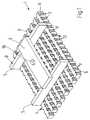
- the electrode 1consists of a plurality of rod-shaped electrode elements 2, which are provided on their side surfaces with recesses 3, and on their upper edge 4 are connected to current distributors 5 in the form of flat profiles by welding; on their lower edge, or in the area of their lateral surfaces 6, the electrode elements 2 have an electrocatalytic coating, which is symbolically provided with reference number 7.
- the upper edges 8 of the rectangular profiles serving as current distributors 5are connected to a main current distributor 9, which has a connection opening 10 for electrical and mechanical connection to a current supply bolt, not shown here; it is a so-called three-level electrode, which is known from DE-PS 29 49 495 and US-PS 43 64811. Since the side surfaces 11 are substantially larger than the base surfaces 12 of the recess, an enlarged outer surface of the electrode element 2 is available for the electrochemical conversion.
- the ratio of base area to side areais in the range from 1: 1.5 to 1: 3, preferably 1: 2.
- the rod-shaped electrode element 2 shown in detailhas recesses 3 on its two side surfaces, which alternate with bulges 13 in a meandering manner, so that, seen in the cross section of the electrode element 2, a recess 3 is opposite a bulge 13; the ratio of the width of the recess b to the height of the recess h is in the range from 1: 2 to 1: 2.5, so that the total size of the side surfaces 11 that is available for the electrochemical conversion is significantly larger than the omitted base surfaces 12 the recess in the area of the surface of the lower edge 14 and upper edge 4 of the electrode element.
- the electrocatalytic coating 7is applied in the entire region of the lower edge 14, or the base surface facing the mercury, in the region of the lateral surfaces 6 of the bulges 13, the side surfaces 11 and the recess surfaces 15, it being additionally possible for the upper edge 4 of the electrode element to be included to provide electrocatalytic coating; however, it is also possible to apply the electrocatalytic coating only in the lower region of the lateral surfaces 6, side surfaces 11, bulges 13 and recesses 15 and the bottom surface in the region of the lower edge.
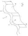
- FIG. 2bshows sections of two adjacent electrode elements 2, between which a meandering electrode gap 17 is formed; Due to the meandering structure, there is not only an increase in the surface area of the active surface, but also a channeling effect for those that arise during the electrochemical reaction Gas bubbles so that a swirling of the gas bubbles within the electrolyte is largely avoided and a rapid removal of the gas bubbles is made possible.
- the ratio of the depth t of the recesses 3 to the gap width s between the electrode elements 2is in the range from 1: 2 to 1: 2.5.
- the ratio of the depth u of the recess in the region of the lower edge 14 to the depth of the recess v in the region of the upper edge 4 of the recess in a ratio of 1: 1 , 8 to 2lies.
- the angle of inclination of the recess surface 15 to the verticalis in the range from 10 to 22 °, in a preferred embodiment approximately 15 °.
- FIG. 4shows a section of a rod-shaped electrode element 2 which has hollow cylindrical recesses 3, the recesses 3 and bulges 13 being arranged in a meandering manner, so that the respective recess 3 is opposite a bulge 13 at its lowest point.
- the actual recesses 13form hollow cylindrical segments, the secants 20 of which are predetermined by the upper edge 4 and lower edge 14 of the electrode elements.
- the ratio of the secant length to the fictitious radius of the hollow cylinderis in the range of 1.6: 1.2.
- FIG. 5shows a detail of a rod-shaped electrode element 2, the recesses 3 of which are formed in the form of hollow cone segments, the recess surface 15 formed by a truncated cone in the region adjacent to the bulge 13 according to the cross section along line AB with the vertical having an angle in the range from 10 to 22 °, preferably forms 16 °.
- an additional chimney effectto collect the gas bubbles in the lower region of the electrode and an accelerated removal of the gas bubbles instead.
Landscapes
- Chemical & Material Sciences (AREA)
- Engineering & Computer Science (AREA)
- Chemical Kinetics & Catalysis (AREA)
- Electrochemistry (AREA)
- Materials Engineering (AREA)
- Metallurgy (AREA)
- Organic Chemistry (AREA)
- Electrodes For Compound Or Non-Metal Manufacture (AREA)
- Electrolytic Production Of Non-Metals, Compounds, Apparatuses Therefor (AREA)
Abstract
Description
Translated fromGermanDie Erfindung betrifft eine Elektrode für Elektrolysezellen, insbesondere für Quecksilber-Chloralkali-Elektrolysezellen mit Stromzuführungen über Stäbe oder Stromzuführungsbolzen und Stromverteilern in Form von hochkant stehenden, mit Abstand zueinander angeordneten Flachprofilen, die an ihrer Unterkante mit senkrecht zu ihnen angeordneten aktivierten Elektrodenteilen aus bis zu 2 mm dicken, hochkant stehenden Flachprofilen mit vertikalen Außenseiten durch Verschweißen verbunden sind, wobei die aktivierten Elektrodenteile aus einer größeren Zahl von Einzelelementen bestehen als die Stromverteiler, und die aktivierten Elektrodenteile mit einem Spalt von wenigstens 2 mm zueinander angeordnet sind.The invention relates to an electrode for electrolytic cells, in particular for mercury-chlor-alkali electrolytic cells with current leads via rods or current lead bolts and current distributors in the form of upright standing, spaced-apart flat profiles, the activated electrode parts of up to 2 of which are arranged on their lower edge with perpendicular to them mm thick, upright flat profiles are connected to vertical outer sides by welding, the activated electrode parts consisting of a larger number of individual elements than the current distributors, and the activated electrode parts being arranged with a gap of at least 2 mm to one another.
Aus der US-PS 40 22 679 ist eine Elektrode für Quecksilber-Chloralkali-Elektrolysezellen mit Stromzuführungen über Stäbe oder Stromzuführungsbolzen bekannt, welche im Abstand zueinander angeordnete Flachprofile aufweist, die an ihrer Unterkante mit senkrecht zu ihnen angeordneten aktivierten Elektrodenteilen verbunden ist, wobei die aktivierten Elektrodenteile aus einer größeren Zahl von Einzelelementen bestehen, als die Stromfahrteile und die Einzelemente im Querschnitt gesehen eine sich verjüngende Unterkante aufweisen, die im wesentlichen abgasförmig ausgebildet ist; als problematisch erweist sich bei solchen kreis- bzw. halbkreisförmigen Ausgestaltungen die Abfuhr der bei der Elektrolyse entstehenden Gasblasen, da diese einerseits den Ionenaustausch im elektrolytischen Spalt zwischen den Halbkreisprofilen und der Quecksilberkathode behindern, andererseits keine rasche Abzugsmöglichkeit haben, so daß im unteren Bereich der Profilanode mit einer Art Gasblasen-polster gerechnet werden muß; weiterhin ist die Höhe der Aktivierungsbeschichtung auf den Elektroden verhältnismäßig hoch, so daß auf die vom Elektrodenspalt verhältnismäßig weit entfernten Bereiche mit edelmetallhaltigen Substanzen versehen sind, jedoch praktisch kaum noch zu elektrochemischen Umsetzung beitragen.From US-PS 40 22 679 an electrode for mercury-chlor-alkali electrolysis cells with current leads via rods or current lead bolts is known, which has spaced-apart flat profiles, which is connected at their lower edge to perpendicularly arranged activated electrode parts, the activated ones Electrode parts consist of a larger number of individual elements than the current parts and the individual elements have a tapering lower edge, seen in cross section, which is essentially formed in the form of a gas; The removal of the gas bubbles produced during electrolysis proves to be problematic in the case of such circular or semicircular configurations, since on the one hand they hinder the ion exchange in the electrolytic gap between the semicircular profiles and the mercury cathode, and on the other hand they have no rapid possibility of removal, so that in the lower area of the profile anode a kind of gas bubble cushion must be expected; furthermore, the height of the activation coating on the electrodes is relatively high, so that are provided with precious metal-containing substances on the areas that are relatively far away from the electrode gap, but practically hardly contribute to electrochemical conversion.
Weiterhin ist aus der US-PS 43 64 811 eine Anode für Quecksilber-Chloralkali-Elektrolysezellen mit Stromzuführung über einen Stab oder Bolzen bekannt, der mit aktivierten Elektrodenteilen aus Flachprofilen über der Stromverteilung dienenden und quer dazu verlaufenden Stromverteilern in Form von Rechteckprofilen verbunden ist; auch hier besteht die Gefahr der Bildung eines Gaspolsters im Elektrodenspalt, bzw. unterhalb der horizontal verlaufenden Unterkante der Elektrodenelemente, so daß eine rasche elektrochemische Umsetzung mit ausreichender Ionenzufuhr nicht möglich ist und die Umsetzung aufgrund der Gaserzeugung behindert wird; auch wenn eine günstige Stromverteilung über drei Leiterebenen mit optimal dimensionierten Flachprofilen hier möglich ist, stellt sich doch die Frage einer raschen elektro- chemischen Umsetzung im Elektrodenspalt und deren Behinderung durch Gasblasenerzeugung, bzw. Bildung eines Gaspolsters.Furthermore, from US-PS 43 64 811 an anode for mercury-chlor-alkali electrolysis cells with current supply via a rod or bolt is known, which is connected to activated electrode parts made of flat profiles above the current distribution and transverse current distributors in the form of rectangular profiles; here too there is a risk of a gas cushion being formed in the electrode gap or below the horizontally running lower edge of the electrode elements, so that rapid electrochemical conversion with sufficient ion supply is not possible and the conversion is hindered due to the gas generation; Even if a favorable current distribution over three conductor levels with optimally dimensioned flat profiles is possible here, the question arises of a rapid electrochemical conversion in the electrode gap and its hindrance due to gas bubble generation or the formation of a gas cushion.
Die Problematik der elektrochemischen Umsetzung spielt auch bei Membran-Elektrolysezellen eine wichtige Rolle, wie aus der EP-PS 204 126 zu entnehmen ist; um eine Behinderung des Stromtransports durch Gasblasen zu vermeiden und eine Verbesserung der energieausnutzung zu erzielen, weisen die der Membran benachbarten Elektrodenteile Ausnehmungen auf, die eine verbesserte elektrochemische Umsetzung aufgrund der Oberflächenvergrößerung des aktiven Elektrodenbereichs und der Gasabführung ermöglichen.The problem of electrochemical conversion also plays an important role in membrane electrolysis cells, as can be seen from EP-PS 204 126; In order to avoid a hindrance to the transport of electricity by gas bubbles and to achieve an improvement in energy efficiency, the electrode parts adjacent to the membrane have recesses which enable improved electrochemical conversion due to the surface enlargement of the active electrode area and the gas removal.
Aufgabe der Erfindung ist es, die Elektroden, bzw. Anoden für die Chloralkali-Elektrolysezelle so auszugestalten, daß der Gasabzug aus dem Bereich des Elektrodenspalts gefördert wird und eine möglichst gasblasenfreie Grenzfläche zwischen Anode und Elektrolyt im Bereich des Elektrodenspaltes zur Verfügung steht; darüberhinaus soll eine hohe Energieausnutzung bei der Elektrolyse durch niedrige Elektrodenspannung erzielt werden.The object of the invention is to design the electrodes or anodes for the chlor-alkali electrolysis cell in such a way that the gas removal is promoted from the area of the electrode gap and an interface between the anode and electrolyte in the area of the electrode gap which is as gas-free as possible is available; in addition, high energy utilization in electrolysis is to be achieved by means of low electrode voltage.
Die Aufgabe wird durch die kennzeichnenden Merkmale des Anspruchs 1 gelöst.The object is achieved by the characterizing features of claim 1.
Als besonders vorteilhaft erweist es sich, daß praktisch keine Verwirbelung des Elektrolyt-Gasgemischs im Elektrodenspalt mehr stattfindet, so daß vorteilhafterweise die Elektrodenspannung niedrig gehalten werden kann.It has proven to be particularly advantageous that there is practically no swirling of the electrolyte-gas mixture in the electrode gap, so that the electrode voltage can advantageously be kept low.
Ein weiterer Vorteil ist in der Vergrößerung der im Seitenbereich befindlichen aktiven Fläche zu sehen. In einer bevorzugten Ausführungsform sind die Ausnehmungen von oben im Querschnitt gesehen U-förmig ausgebildet, wobei sich insbesondere bei Ausnehmungen in Form eines Hohlquaders eine starke Vergrößerung der aktiven Oberfläche im Bereich der Seitenteile ergibt, so daß sich eine rasche elektrochemische Umsetzung mit verbessertem Wirkungsgrad ergibt.Another advantage is the enlargement of the active area in the side area. In a preferred embodiment, the recesses are U-shaped when viewed from above in cross section, with recesses in the form of a hollow cuboid in particular resulting in a large increase in the active surface area in the region of the side parts, so that there is rapid electrochemical conversion with improved efficiency.
Vorzugsweise werden Elektrodenelemente eingesetzt, deren U-förmige Ausnehmungen im Walzverfahren eingebracht sind; ein wesentlicher Vorteil ist in dem preisgünstigen Verfahren zur Herstellung einer Vielzahl solcher Elektrodenelemente zu sehen, wobei der zunächst mit Ausnehmungen versehene gewalzte Strang durch einen Schneidevorgang in die einzelnen Elektrodenelement zerlegt wird. Es ist jedoch auch möglich, die Ausnehmungen durch Fräsen einzubringen.Electrode elements are preferably used, the U-shaped recesses of which are made in the rolling process; An essential advantage is to be seen in the inexpensive method for producing a large number of such electrode elements, the rolled strand initially provided with recesses being broken down into the individual electrode elements by a cutting process. However, it is also possible to make the recesses by milling.
Weitere vorteilhafte Ausgestaltungen der Erfindung sind in den Unteransprüchen angegeben.Further advantageous embodiments of the invention are specified in the subclaims.
Im folgenden ist der Gegenstand der Erfindung anhand der Figuren 1, 2a, 2b, 3, 4 und 5 näher erläutert.
- Figur 1 zeigt schematisch eine Elektrode für Elektrolysezellen, deren aktive Elektrodenelemente an ihren Seitenflächen Ausnehmungen aufweisen;
- Figur 2a zeigt ausschnittsweise ein Elektrodenelement, an dem die geometrischen Verhältnisse der Aussparungen erkennbar sind;
- Figur 2b zeigt ausschnittsweise zwei benachbarte Elektrodenelemente mit dazwischen liegendem Elektrodenspalt.
Figur 3 zeigt ausschnittsweise ein Elektrodenelement mit keilförmigen Ausnehmungen, deren kaminartiger Querschnitt sich nach oben hin verjüngt;Figur 4 zeigt ausschnittsweise ein Elektrodenelement mit hohlzylindrischen Ausnehmungen;Figur 5 zeigt ausschnittsweise ein Elektrodenelement mit kegelstumpfförmigen Ausnehmungen, welche sich nach oben hin verjüngen.
- FIG. 1 schematically shows an electrode for electrolytic cells, the active electrode elements of which have recesses on their side surfaces;
- FIG. 2a shows a section of an electrode element on which the geometrical relationships of the cutouts can be recognized;
- FIG. 2b shows sections of two adjacent electrode elements with an electrode gap between them.
- FIG. 3 shows a section of an electrode element with wedge-shaped recesses whose chimney-like cross section tapers towards the top;
- FIG. 4 shows sections of an electrode element with hollow cylindrical recesses;
- FIG. 5 shows a section of an electrode element with frustoconical recesses which taper towards the top.
Gemäß Figur 1 besteht die Elektrode 1 aus einer Vielzahl von stabförmigen Elektrodenelementen 2, die an ihren Seitenflächen mit Ausnehmungen 3 versehen sind, und an ihrer Oberkante 4 mit Stromverteilern 5 in Form von Flachprofilen durch Verschweißen verbunden sind; an ihrer Unterkante, bzw. im Bereich ihrer seitlichen Flächen 6 weisen die Elektrodenelemente 2 eine elektrokatalytische Beschichtung auf, die symbolisch mit Bezugsziffer 7 versehen ist. Die Oberkanten 8 der als Stromverteiler 5 dienenden Rechteckprofile sind mit einem Hauptstromverteiler 9 verbunden, welcher eine Anschlußöffnung 10 zur elektrischen und mechanischen Verbindung mit einem hier nicht dargestellten Stromzuführungsbolzen aufweist; es handelt sich hierbei um eine sogenannte Drei-Ebenen-Elektrode, welche aus der DE-PS 29 49 495 bzw. US-PS 43 64811 bekannt ist. Da die Seitenflächen 11 wesentlich größer sind als die Grundflächen 12 der Ausnehmung steht für die elektrochemische Umsetzung eine vergrößerte Außenoberfläche des Elektrodenelements 2 zur Verfügung. Das Verhältnis von Grundfläche zu Seitenfläche liegt im Bereich von 1:1,5 bis 1:3, vorzugsweise bei 1:2.According to Figure 1, the electrode 1 consists of a plurality of rod-
Gemäß Figur 2a weist das ausschnittsweise dargestellte stabförmige Elektrodenelement 2 an seinen beiden Seitenflächen 11 Ausnehmungen 3 auf, welche sich mit Ausbuchtungen 13 mäanderförmig abwechseln, so daß im Querschnitt des Elektrodenelements 2 gesehen jeweils eine Ausnehmung 3 einer Ausbuchtung 13 gegenüberliegt; das Verhältnis der Breite der Ausnehmung b zur Höhe der Ausnehmung h liegt im Bereich von 1:2 bis 1:2,5, so daß die Gesamtgröße der Seitenflächen 11, die für die elektrochemische Umsetzung zur Verfügung steht wesentlich größer ist als die entfallenden Grundflächen 12 der Ausnehmung im Bereich der Fläche der Unterkante 14 und Oberkante 4 des Elektrodenelements. Die elektrokatalytische Beschichtung 7 ist im gesamten Bereich der Unterkante 14, bzw. der dem Quecksilber zugewandten Bodenfläche, im Bereich der seitlichen Flächen 6 der Ausbuchtungen 13, der Seitenflächen 11 sowie der Ausnehmungsflächen 15 aufgebracht, wobei es möglich ist zusätzlich die Oberkante 4 des Elektrodenelements mit elektrokatalytischer Beschichtung zu versehen; es ist jedoch auch möglich, die elektrokatalytische Beschichtung nur im unteren Bereich der seitlichen Flächen 6, Seitenflächen 11, Ausbuchtungen 13 und Ausnehmungen 15 sowie der Bodenfläche im Bereich der Unterkante aufzubringen.According to FIG. 2a, the rod-
Figur 2b zeigt ausschnittsweise zwei benachbarte Elektrodenelemente 2, zwischen denen ein mäanderförmiger Elektrodenspalt 17 ausgebildet ist; aufgrund der mäanderförmigen Struktur ergibt sich nicht nur eine Oberflächenvergrößerung der aktiven Oberfläche sondern auch zusätzlich ein Kanalisierungseffekt für die bei der elektrochemischen Umsetzung entstehenden Gasblasen, so daß eine Verwirbelung der Gasblasen innerhalb des Elektrolyten weitgehend vermieden wird und ein rascher Abzug der Gasblasen ermöglich wird. Das Verhältnis der Tiefe t der Ausnehmungen 3 zur Spaltbreite s zwischen den Elektrodenelementen 2 liegt im Bereich von 1:2 bis 1:2,5.FIG. 2b shows sections of two
Gemäß Figur 3 ist es möglich, die Ausnehmungen 3 des ausschnittsweise dargestellten stabförmigen Elektrodenelements 2 keilförmig auszugestalten, wobei das Verhältnis der Tiefe u der Ausnehmung im Bereich der Unterkante 14 zur Tiefe der Ausnehmung v im Bereich der Oberkante 4 der Ausnehmung im Verhältnis von 1:1,8 bis 2 liegt. Der Neigungswinkel der Ausnehmungsfläche 15 zur Vertikalen liegt im Bereich von 10 bis 22°, in einer bevorzugten Ausführungsform bei ca. 15°.According to FIG. 3, it is possible to design the
Aufgrund der Keilform ergibt sich im besonders aktiven Bereich des Elektrodenspalts zwischen der hier nicht dargestellten Quecksilberkathode und dem Elektrodenelement 2 eine verhältnismäßig starke Gasblasentwicklung, welche durch den sich nach unten keilförmig erweiternden Raum der Aussparungen gezielt nach oben abgeführt werden kann, wobei aufgrund des sich verjüngenden Querschnitts zusätzlich eine Art Kamineffekt zur verbesserten Ausschleusung der Gasblasen erzielt wird.Due to the wedge shape, in the particularly active area of the electrode gap between the mercury cathode (not shown here) and the
Figur 4 zeigt ausschnittsweise ein stabförmiges Elektrodenelement 2, das hohlzylindrische Ausnehmungen 3 aufweist, wobei die Ausnehmungen 3 und Ausbuchtungen 13 mäanderförmig angeordnet ist, so daß die jeweilige Ausnehmung 3 an ihrer tiefsten Stelle jeweils eine Ausbuchtung 13 gegenüberliegt. Die eigentlichen Ausnehmungen 13 bilden hohlzylindrische Segmente, deren Sekanten 20 durch die Oberkante 4 und Unterkante 14 der Elektrodenelemente vorgegeben sind. Das Verhältnis der Sekantenlänge zum fiktiven Radius der Hohlzylinder liegt im Bereich von 1,6:1,2.FIG. 4 shows a section of a rod-
Als vorteilhaft erweist sich bei einer solchen hohlzylindrischen Ausnehmung die verhältnismäßig einfache Herstellungsmöglichkeit der Ausnehmungen durch Fräsen.With such a hollow cylindrical recess, the relatively simple possibility of producing the recesses by milling has proven to be advantageous.
Figur 5 zeigt ausschnittsweise ein stabförmiges Elektrodenelement 2, dessen Ausnehmungen 3 in Form von Hohlkegelsegmenten ausgebildet sind, wobei die durch eine Kegelstumpfmantel gebildete Ausnehmungsfläche 15 im Nachbarbereich zur Ausbuchtung 13 gemäß Querschnitt entlang Linie AB mit der Vertikalen einen Winkel im Bereich von 10 bis 22°, vorzugsweise 16° bildet. Auch hier tritt ähnlich wie in der anhand Figur 3 beschriebenen keilförmigen Ausnehmungsausbildung ein zusätzlicher Kamineffekt zum Sammeln der Gasblasen im unteren Bereich der Elektrode und eine beschleunigte Abführung der Gasblasen statt.FIG. 5 shows a detail of a rod-
Claims (8)
Translated fromGermanApplications Claiming Priority (2)
| Application Number | Priority Date | Filing Date | Title |
|---|---|---|---|
| DE4419274ADE4419274A1 (en) | 1994-06-01 | 1994-06-01 | Electrode for electrolytic cells |
| DE4419274 | 1994-06-01 |
Publications (2)
| Publication Number | Publication Date |
|---|---|
| EP0685576A1true EP0685576A1 (en) | 1995-12-06 |
| EP0685576B1 EP0685576B1 (en) | 1997-04-16 |
Family
ID=6519605
Family Applications (1)
| Application Number | Title | Priority Date | Filing Date |
|---|---|---|---|
| EP95102062AExpired - LifetimeEP0685576B1 (en) | 1994-06-01 | 1995-02-15 | Electrode for electrolysis cell |
Country Status (4)
| Country | Link |
|---|---|
| US (1) | US5589044A (en) |
| EP (1) | EP0685576B1 (en) |
| DE (2) | DE4419274A1 (en) |
| ES (1) | ES2100750T3 (en) |
Cited By (1)
| Publication number | Priority date | Publication date | Assignee | Title |
|---|---|---|---|---|
| CN113355689A (en)* | 2021-05-07 | 2021-09-07 | 北京仿生界面科学未来技术研究院 | Qinqi-dispelling and qi-dispelling cooperative confinement electrode and preparation method thereof |
Families Citing this family (6)
| Publication number | Priority date | Publication date | Assignee | Title |
|---|---|---|---|---|
| US5849164A (en)* | 1996-06-27 | 1998-12-15 | Eltech Systems Corporation | Cell with blade electrodes and recirculation chamber |
| AU767865B2 (en)* | 1999-01-08 | 2003-11-27 | Rio Tinto Alcan International Limited | Aluminium electrowinning cells with oxygen-evolving anodes |
| DE10013297B4 (en)* | 2000-03-17 | 2005-06-30 | Vlm Gmbh | Fastening device for fastening the support of a lamp head to a support tube |
| ITMI20010643A1 (en)* | 2001-03-27 | 2002-09-27 | De Nora Elettrodi Spa | ANODIC STRUCTURE FOR MERCURY CATHODE ELECTOLYTIC CELLS |
| US8771497B2 (en)* | 2007-04-20 | 2014-07-08 | Mitsui Chemicals, Inc. | Electrolyzer, electrodes used therefor, and electrolysis method |
| EP4248503A4 (en)* | 2020-11-23 | 2025-04-30 | Lawrence Livermore National Security, LLC | CORRUGATED ELECTRODES FOR ELECTROCHEMICAL APPLICATIONS |
Citations (1)
| Publication number | Priority date | Publication date | Assignee | Title |
|---|---|---|---|---|
| US3929607A (en)* | 1974-02-25 | 1975-12-30 | Ici Ltd | Anodes for electrochemical processes |
Family Cites Families (4)
| Publication number | Priority date | Publication date | Assignee | Title |
|---|---|---|---|---|
| US4022679A (en)* | 1973-05-10 | 1977-05-10 | C. Conradty | Coated titanium anode for amalgam heavy duty cells |
| DE2949495C2 (en)* | 1979-12-08 | 1983-05-11 | Heraeus-Elektroden Gmbh, 6450 Hanau | Electrode for electrolytic cells |
| GB8407871D0 (en)* | 1984-03-27 | 1984-05-02 | Ici Plc | Electrode and electrolytic cell |
| DE3519573A1 (en)* | 1985-05-31 | 1986-12-04 | Conradty GmbH & Co Metallelektroden KG, 8505 Röthenbach | ELECTRODE FOR MEMBRANE ELECTROLYSIS |
- 1994
- 1994-06-01DEDE4419274Apatent/DE4419274A1/ennot_activeWithdrawn
- 1995
- 1995-02-15ESES95102062Tpatent/ES2100750T3/ennot_activeExpired - Lifetime
- 1995-02-15DEDE59500185Tpatent/DE59500185D1/ennot_activeExpired - Fee Related
- 1995-02-15EPEP95102062Apatent/EP0685576B1/ennot_activeExpired - Lifetime
- 1995-05-01USUS08/431,898patent/US5589044A/ennot_activeExpired - Fee Related
Patent Citations (1)
| Publication number | Priority date | Publication date | Assignee | Title |
|---|---|---|---|---|
| US3929607A (en)* | 1974-02-25 | 1975-12-30 | Ici Ltd | Anodes for electrochemical processes |
Cited By (2)
| Publication number | Priority date | Publication date | Assignee | Title |
|---|---|---|---|---|
| CN113355689A (en)* | 2021-05-07 | 2021-09-07 | 北京仿生界面科学未来技术研究院 | Qinqi-dispelling and qi-dispelling cooperative confinement electrode and preparation method thereof |
| CN113355689B (en)* | 2021-05-07 | 2023-03-31 | 北京蕴超仿生智能科技发展有限公司 | Qinqi-dispelling and qi-dispelling cooperative confinement electrode and preparation method thereof |
Also Published As
| Publication number | Publication date |
|---|---|
| DE4419274A1 (en) | 1995-12-07 |
| US5589044A (en) | 1996-12-31 |
| EP0685576B1 (en) | 1997-04-16 |
| DE59500185D1 (en) | 1997-05-22 |
| ES2100750T3 (en) | 1997-06-16 |
Similar Documents
| Publication | Publication Date | Title |
|---|---|---|
| DE2806962B2 (en) | Galvanic power source with comb-like interlocking bipolar electrode pairs | |
| DE2262173C3 (en) | ||
| DE2135873B2 (en) | Cell top for amalgam high-load cells | |
| EP0685576B1 (en) | Electrode for electrolysis cell | |
| DE3519573A1 (en) | ELECTRODE FOR MEMBRANE ELECTROLYSIS | |
| DE2059868A1 (en) | Electrode plate for electrolysis | |
| DE2538000C3 (en) | Bipolar electrode construction for a membrane-free electrolysis cell | |
| DE2904441C2 (en) | Busbar system of electrolysis cells for aluminum production | |
| EP2156495B1 (en) | Repeater unit for a fuel cell stack | |
| DE2949495C2 (en) | Electrode for electrolytic cells | |
| DE1947157B2 (en) | ELECTROLYSIS CELL WITH REMOVABLE SIDE PANEL CARRYING ELECTRODES | |
| DE3017006C2 (en) | ||
| EP0097991B1 (en) | Membrane-electrolysis cell with vertically arranged electrodes | |
| DE1276768B (en) | Seawater battery | |
| DE2923818A1 (en) | ELECTRODE COMPARTMENT | |
| DE60008599T2 (en) | END BOX FOR AN ELECTRODIALYZER AND ELECTRO-DIALYSIS METHOD | |
| DE2845832A1 (en) | DEVICE FOR DIAPHRAGMA ELECTROLYSIS | |
| EP0035131B1 (en) | Gas developing metal electrode for electrochemical processes | |
| DE2753885A1 (en) | ELECTROLYTIC CELL | |
| DE2312458A1 (en) | ELECTROLYSIS CELL WITH VERTICAL METAL LANODES FIXED IN THE BOTTOM OF THE CELL | |
| EP0685575B1 (en) | Electrode for electrolysis cells | |
| DD285125B5 (en) | Electrode for gas-developing electrolytic processes | |
| DE2929043A1 (en) | DISINFECTING DEVICE | |
| DE2029640C (en) | Anode for amalgam high-load cells | |
| DE2408392A1 (en) | ANODES FOR ELECTRO-CHEMICAL PROCESSES |
Legal Events
| Date | Code | Title | Description |
|---|---|---|---|
| PUAI | Public reference made under article 153(3) epc to a published international application that has entered the european phase | Free format text:ORIGINAL CODE: 0009012 | |
| 17P | Request for examination filed | Effective date:19950227 | |
| AK | Designated contracting states | Kind code of ref document:A1 Designated state(s):BE DE ES FR GB IT SE | |
| GRAG | Despatch of communication of intention to grant | Free format text:ORIGINAL CODE: EPIDOS AGRA | |
| GRAH | Despatch of communication of intention to grant a patent | Free format text:ORIGINAL CODE: EPIDOS IGRA | |
| 17Q | First examination report despatched | Effective date:19960812 | |
| GRAH | Despatch of communication of intention to grant a patent | Free format text:ORIGINAL CODE: EPIDOS IGRA | |
| GRAA | (expected) grant | Free format text:ORIGINAL CODE: 0009210 | |
| AK | Designated contracting states | Kind code of ref document:B1 Designated state(s):BE DE ES FR GB IT SE | |
| GBT | Gb: translation of ep patent filed (gb section 77(6)(a)/1977) | Effective date:19970417 | |
| REF | Corresponds to: | Ref document number:59500185 Country of ref document:DE Date of ref document:19970522 | |
| REG | Reference to a national code | Ref country code:ES Ref legal event code:FG2A Ref document number:2100750 Country of ref document:ES Kind code of ref document:T3 | |
| ET | Fr: translation filed | ||
| PGFP | Annual fee paid to national office [announced via postgrant information from national office to epo] | Ref country code:SE Payment date:19980126 Year of fee payment:4 | |
| PGFP | Annual fee paid to national office [announced via postgrant information from national office to epo] | Ref country code:ES Payment date:19980209 Year of fee payment:4 | |
| PLBE | No opposition filed within time limit | Free format text:ORIGINAL CODE: 0009261 | |
| STAA | Information on the status of an ep patent application or granted ep patent | Free format text:STATUS: NO OPPOSITION FILED WITHIN TIME LIMIT | |
| PGFP | Annual fee paid to national office [announced via postgrant information from national office to epo] | Ref country code:FR Payment date:19980227 Year of fee payment:4 | |
| PGFP | Annual fee paid to national office [announced via postgrant information from national office to epo] | Ref country code:BE Payment date:19980320 Year of fee payment:4 | |
| 26N | No opposition filed | ||
| PG25 | Lapsed in a contracting state [announced via postgrant information from national office to epo] | Ref country code:SE Free format text:LAPSE BECAUSE OF NON-PAYMENT OF DUE FEES Effective date:19990216 Ref country code:ES Free format text:LAPSE BECAUSE OF NON-PAYMENT OF DUE FEES Effective date:19990216 | |
| PG25 | Lapsed in a contracting state [announced via postgrant information from national office to epo] | Ref country code:BE Free format text:LAPSE BECAUSE OF NON-PAYMENT OF DUE FEES Effective date:19990228 | |
| BERE | Be: lapsed | Owner name:HERAEUS ELEKTROCHEMIE G.M.B.H. Effective date:19990228 | |
| PG25 | Lapsed in a contracting state [announced via postgrant information from national office to epo] | Ref country code:FR Free format text:LAPSE BECAUSE OF NON-PAYMENT OF DUE FEES Effective date:19991029 | |
| EUG | Se: european patent has lapsed | Ref document number:95102062.7 | |
| REG | Reference to a national code | Ref country code:FR Ref legal event code:ST | |
| REG | Reference to a national code | Ref country code:ES Ref legal event code:FD2A Effective date:20010910 | |
| REG | Reference to a national code | Ref country code:GB Ref legal event code:IF02 | |
| PG25 | Lapsed in a contracting state [announced via postgrant information from national office to epo] | Ref country code:IT Free format text:LAPSE BECAUSE OF NON-PAYMENT OF DUE FEES;WARNING: LAPSES OF ITALIAN PATENTS WITH EFFECTIVE DATE BEFORE 2007 MAY HAVE OCCURRED AT ANY TIME BEFORE 2007. THE CORRECT EFFECTIVE DATE MAY BE DIFFERENT FROM THE ONE RECORDED. Effective date:20050215 | |
| PGFP | Annual fee paid to national office [announced via postgrant information from national office to epo] | Ref country code:GB Payment date:20070216 Year of fee payment:13 Ref country code:DE Payment date:20070216 Year of fee payment:13 | |
| GBPC | Gb: european patent ceased through non-payment of renewal fee | Effective date:20080215 | |
| PG25 | Lapsed in a contracting state [announced via postgrant information from national office to epo] | Ref country code:DE Free format text:LAPSE BECAUSE OF NON-PAYMENT OF DUE FEES Effective date:20080902 | |
| PG25 | Lapsed in a contracting state [announced via postgrant information from national office to epo] | Ref country code:GB Free format text:LAPSE BECAUSE OF NON-PAYMENT OF DUE FEES Effective date:20080215 |