EP0684678B1 - Methods and apparatus for identifying faulted phases on an electric power transmission line - Google Patents
Methods and apparatus for identifying faulted phases on an electric power transmission lineDownload PDFInfo
- Publication number
- EP0684678B1 EP0684678B1EP95302101AEP95302101AEP0684678B1EP 0684678 B1EP0684678 B1EP 0684678B1EP 95302101 AEP95302101 AEP 95302101AEP 95302101 AEP95302101 AEP 95302101AEP 0684678 B1EP0684678 B1EP 0684678B1
- Authority
- EP
- European Patent Office
- Prior art keywords
- circuit
- fault
- line
- values
- circuits
- Prior art date
- Legal status (The legal status is an assumption and is not a legal conclusion. Google has not performed a legal analysis and makes no representation as to the accuracy of the status listed.)
- Expired - Lifetime
Links
- 230000005540biological transmissionEffects0.000titleclaimsabstractdescription24
- 238000000034methodMethods0.000titleclaimsabstractdescription24
- 238000004891communicationMethods0.000claimsdescription4
- 238000005259measurementMethods0.000abstractdescription10
- 238000012544monitoring processMethods0.000description28
- 239000011159matrix materialSubstances0.000description11
- 238000004364calculation methodMethods0.000description5
- 230000001902propagating effectEffects0.000description5
- 238000010586diagramMethods0.000description4
- 230000001419dependent effectEffects0.000description1
- 238000009795derivationMethods0.000description1
- 239000000835fiberSubstances0.000description1
- 238000007689inspectionMethods0.000description1
Images


Classifications
- H—ELECTRICITY
- H02—GENERATION; CONVERSION OR DISTRIBUTION OF ELECTRIC POWER
- H02H—EMERGENCY PROTECTIVE CIRCUIT ARRANGEMENTS
- H02H7/00—Emergency protective circuit arrangements specially adapted for specific types of electric machines or apparatus or for sectionalised protection of cable or line systems, and effecting automatic switching in the event of an undesired change from normal working conditions
- H02H7/26—Sectionalised protection of cable or line systems, e.g. for disconnecting a section on which a short-circuit, earth fault, or arc discharge has occured
- H02H7/265—Sectionalised protection of cable or line systems, e.g. for disconnecting a section on which a short-circuit, earth fault, or arc discharge has occured making use of travelling wave theory
- H—ELECTRICITY
- H02—GENERATION; CONVERSION OR DISTRIBUTION OF ELECTRIC POWER
- H02H—EMERGENCY PROTECTIVE CIRCUIT ARRANGEMENTS
- H02H7/00—Emergency protective circuit arrangements specially adapted for specific types of electric machines or apparatus or for sectionalised protection of cable or line systems, and effecting automatic switching in the event of an undesired change from normal working conditions
- H02H7/26—Sectionalised protection of cable or line systems, e.g. for disconnecting a section on which a short-circuit, earth fault, or arc discharge has occured
- H02H7/267—Sectionalised protection of cable or line systems, e.g. for disconnecting a section on which a short-circuit, earth fault, or arc discharge has occured for parallel lines and wires
Definitions
- This inventionrelates to methods and apparatus for identifying faulted phases on an electric power transmission line.
- a method for identifying faulted phases on the occurrence of single phase faults simultaneously on both circuits of a double circuit electric power transmission linecomprising: deriving for at least one circuit first and second signals respectively representative of the voltage and current at one end of said line; utilising said first and second signals together with parameters of the line to derive a third signal representative of the travelling wave arriving at said one end of said line in consequence of the occurrence of said faults on both circuits, said third signal including two components, one said component being attributable to the fault on one circuit and the other said component being attributable to the fault on the other circuit; utilising said third signal to deduce the values of the two components of said third signal respectively attributable to said faults for each of a plurality of assumptions regarding which particular phases on the two circuits are faulted; and utilising the deduced values for the different assumptions to determine which assumption is most likely to be valid.
- the determination as to which assumption is most likely to be validmay be made on the basis of changes with time of the value of at least one of said components for different said assumptions, i.e. on inspection of the shapes of the waveform of said at least one component for different said assumptions.
- the determinationis made on the basis of a comparison of the relative values of said two components for different said assumptions.
- second and third signalsmay be derived for both circuits; amplitudes of said two components are deduced utilising the each said third signal separately; and the determination as to which assumption is most likely to be valid is made on the basis of a comparison of the values obtained using the comparison of the relative values of said two components for different said assumptions.
- second and third signalsare derived for both circuits and values of said two components are deduced utilising both said third signals.
- the determination as to which assumption is most likely to be validis suitably made on the basis of comparison of values obtained using the third signal for one circuit with values obtained using the third signal for the other circuit.
- the inventionalso provides apparatus for carrying out a method according to the invention.
- the disturbance created by the fault at the fault pointcan be considered as travelling waves propagating away from the fault point.
- the fault reflection matrix [kvf]is dependent on the nature of the fault i.e. the fault type, that is, which phase or phases is/are faulted and the fault impedances.
- one of the two waves T1 and T2(wave T1 in Figure 2) is incident at a monitoring point M at one end of the line L shortly after the occurrence of the fault.
- a reflected wave R1is also present at the monitoring point M due to reflection of the wave T1 at the discontinuity D back towards the fault point F.
- equation (3)is strictly true for only a very short period because, as the fault generated travelling waves propagate further through the system, further reflected waves reach the monitoring point M. However, these further waves have a much reduced value so that equation (3) normally gives a good estimate of V1 at the monitoring point M for at least the first 10 milliseconds after the first appearance of fault generated travelling wave T1 at the monitoring point M.
- phase-a to ground faultoccurs on one circuit and a phase-b to ground fault occurs simultaneously on the other circuit
- phases a and bare faulted on both circuits. This will normally result in a three-phase trip on both circuits. If the faulted phases could be properly identified a single-phase trip would be effected on each circuit minimising the interruption of the supply.
- the travelling wave due to the faults arriving at a monitoring point M on circuit 1has two components, one attributable to the fault F1 on circuit 1 and the other to the fault F2 on circuit 2.
- the component due to the fault F1 on circuit 1has a value given by equation (1) above.
- the component due to the fault F2 on circuit 2comprises the wave generated at the fault F2, of a value given by equation (1), after reflection at the discontinuity D at the end of the line L remote from the monitoring point M and propagation through the fault F1 on the circuit 1.
- equation (4)represents three simultaneous equations in phase or modal quantities. For the purposes of fault identification according to the invention the information from ground, i.e. common, mode may be ignored.
- the discontinuity reflection matrix [ ⁇ D]is a unit matrix and all fault resistances are zero.
- the calculationrequired derivation of V1 from measurements of the voltage and current of the resultant travelling wave appearing at the monitoring point M, as described above in relation to equation (3).
- values obtained for A and B for each assumed fault combination using measurements of voltage V and current I taken at a monitoring point M1 on circuit 1 and a corresponding monitoring point M2 on circuit 2are compared to see which of them is greater for the various fault combinations. From the results of these comparisons the true fault combination is deduced. Disconnection of the faulted single phase of each circuit is then effected accordingly, and subsequent reclosure effected, the disconnection and reclosure sequence being repeated, if necessary, as desired.
- Figure 4also illustrates the cases where fault current is present on all three phases or one phase only when the normal tripping strategy is again followed whatever are the values of ⁇ , ⁇ etc.
- a time series of values of A for each possible fault combinationis obtained. From the time series for each fault combination the waveform of the travelling wave voltage generated by the fault on circuit 1 can be deduced. The fault combination which gives the waveform of greatest amplitude is then taken to be the true fault combination.
- the apparatusis intended for use in identification of the faulted phases when single phase faults occur simultaneously on both circuits 11 and 13 of a double circuit three-phase transmission line L which is shown as interconnecting two busbars X and Y.
- the apparatuscomprises measuring equipment at each of two monitoring points M1 and M2 respectively situated at a position near the end of the line connected to busbar X.
- Each measuring equipmentcomprises a voltage sensor 15 or 17 and a current sensor 19 or 21, for measuring the voltages and currents at the monitoring points M1 and M2, low pass filters 23 or 25 which extract power frequency information from the outputs of the sensors 15 and 19 or 17 and 21, an analogue to digital converter 27 or 29 for converting the analogue signals output by the filters 23 or 25 into a series of digital signals representing successive samples of the analogue signals, and a microprocessor, 31 or 33, which receives these digital signals.
- Each of the microprocessors 31 and 33is associated with a keypad 37 or 39 for data and instruction entry, a display 41 or 43, a read only memory (ROM) 45 or 47 in which the line parameters required for carrying out fault identification, e.g. reflection matrices and line surge impedance matrices, are stored, a random access memory (RAM) 49 or 51 which provides temporary variable storage for use by the microprocessors 31 or 33 in operation, and an output port 53 or 55 via which trip signals are passed from the microprocessor 31 or 33 to circuit breaker equipment 57 and 59 on the circuits 11 and 13.
- ROMread only memory
- RAMrandom access memory
- the microprocessors 31 and 33are interconnected via a fibre optic communication link 35 so that the calculations made in them can be compared and decisions regarding fault type made accordingly.
- the voltage and current sensors 15, 17, 19 and 21measure the actual phase voltages and currents on the circuits 11 and 13 at the monitoring points. These voltages and currents are, of course, the resultants of steady state and travelling wave voltages and currents at the monitoring points.
- the digital signals passed to the microprocessors 31 and 33are utilised to isolate the travelling wave voltages and currents from the voltages and currents measured by sensors 15, 17, 19 and 21. This is suitably done in conventional manner by storing, on a continuing basis, signals relating to the immediately preceding cycle of the power system, and substracting from each measured value the stored value obtained for the same point-on-wave of the preceding power system cycle.
- V and Iare taken over a period of 10 milliseconds, i.e. a half cycle at a power frequency of 50Hz.
- a time series of set values of V and Iare taken over a period of 10 milliseconds, i.e. a half cycle at a power frequency of 50Hz.
- thirty-six sets of valuesare obtained.
- Each set of valuesis then used separately to identify the faulted phases and the final tripping decision made on a majority vote basis as regards fault identity.
Landscapes
- Engineering & Computer Science (AREA)
- Theoretical Computer Science (AREA)
- Testing Of Short-Circuits, Discontinuities, Leakage, Or Incorrect Line Connections (AREA)
- Monitoring And Testing Of Transmission In General (AREA)
- Small-Scale Networks (AREA)
- Cable Transmission Systems, Equalization Of Radio And Reduction Of Echo (AREA)
Abstract
Description

- P1
- is the wave propagating directly from the fault F1 on the
circuit 1 to themonitoring point M1 on circuit 1 (i.e. equivalent to wave A of equation(5)) where kvf(1) and kvf(2) assume respectively a phase-a to groundfault oncircuit 1 and a phase-b to ground fault oncircuit 2; - P2
- is the wave propagating directly from the fault F1 on the
circuit 1 to themonitoring point M2 on circuit 2 (i.e. equivalent to wave B of equation(6)) where kvf(1) and (kvf(2)) assume respectively the same groundfaults as for P1; - Q1 and Q2
- are as for P1 and P2 respectively except that kvf(1) and kvf(2)assume respectively a phase-b to ground fault on
circuit 1 and aphase-a to ground fault oncircuit 2; - R1 and R2
- are as for P1 and P2 respectively except that kvf(1) andkvf(2) assume respectively a phase-b to ground fault on
circuit 1 and aphase-c to ground fault oncircuit 2; - S1 and S2
- are as for P1 and P2 respectively except that kvf(1) and kvf(2)assume respectively a phase-c to ground fault on
circuit 1 and aphase-b to ground fault oncircuit 2; - T1 and T2
- are as for P1 and P2 respectively except that kvf(1) and kvf(2) assume respectively a phase-a to ground fault on
circuit 1 and aphase-c fault to ground oncircuit 2; and - W1 and W2
- are as for P1 and P2 respectively except that kvf(1) and kvf(2)assume respectively a phase-c to ground fault on
circuit 1 and aphase-a to ground fault oncircuit 2.
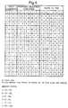
α = P1>P2 β = Q1>Q2 γ = R1>R2
δ = S1>S2 Σ = T1>T2 ζ = W1>W2and
- 1 indicates a condition is satisfied;
- 0 indicates a condition is not satisfied; and
- X indicates it does not matter whether a condition is, or is not satisfied.
Claims (9)
- A method for identifying faulted phases on the occurrence of singlephase faults simultaneously on both circuits (11, 13) of a double circuitelectric power transmission line (L) comprising: deriving for at least onecircuit (11 or 13) first and second signals respectively representative of thevoltage and current at one end of said line(L); utilising said first and secondsignals together with parameters of the line to derive a third signalrepresentative of the travelling wave arriving at said one end of said line (L)in consequence of the occurrence of said faults on both circuits, said thirdsignal including two components, one said component being attributable tothe fault on one circuit and the other said component being attributable tothe fault on the other circuit; utilising said third signal to deduce the valuesof the two components of said third signal respectively attributable to saidfaults for each of a plurality of assumptions regarding which particularphases on the two circuits are faulted; and utilising the deduced values forthe different assumptions to determine which assumption is most likely tobe valid.
- A method according to Claim 1 wherein the determination as to whichassumption is most likely to be valid is made on the basis of a comparisonof the relative values of said two components for different said assumptions.
- A method according to Claim 1 wherein the determination as to whichassumption is most likely to be valid is made on the basis of changes withtime of the value of at least one of said two components for different saidassumptions.
- A method according to Claim 3 wherein the assumption most likelyto be valid is taken to be the assumption which leads to the largestamplitude variation of said at least one component.
- A method according to Claim 1 wherein said first, second and thirdsignals are derived for both said circuits(11, 13); and values of said twocomponents are deduced using both said third signals.
- A method according to Claim 5 wherein the determination as to whichassumption is most likely to be valid is made on the basis of comparison ofvalues obtained using the third signal of one circuit (11) with values obtainedusing the third signal for the other circuit (13).
- An apparatus for identifying faulted phases on the occurrence of singlephase faults simultaneously on both circuits (11, 13) of a double circuitelectric power transmission line (L) comprising: first means (15, 10, 23, 27or 17, 21, 25, 29) for deriving first and second signals respectivelyrepresentative of the value of the voltage and current at one end of at leastone circuit (11 or 13) of said line (L); and means (33) for calculating from thevalues of said first and second signals together with parameters of the line athird signal representative of the value of the travelling wave arriving at saidone end of said line (L) in consequence of the occurrence of said faults onboth circuits, said third signal including two components, one said componentbeing attributable to the fault on one circuit and the other said componentbeing attributable to the fault on the other circuit, and for deducing the valuesof the two components of said third signal respectively attributable to saidfaults for each of a plurality of assumptions regarding which particular phases on the two circuits are faulted, and for utilising the deduced values for thedifferent assumptions to determine which assumption is most likely to bevalid.
- An apparatus according to Claim 7 comprising two said first means (15,19, 23, 27 and 17, 21, 25, 29) and two said calculating and utilising means(33) one for each circuit (11, 13) of the line (L), and a communication link (35)between said means (33) for calculating and utilising.
- An apparatus according to Claim 7 or Claim 8 wherein said first means(15, 19, 23, 27; 17, 21, 25, 29) provides digital signals and said means (33)for calculating and utilising comprises microprocessor means (33).
Applications Claiming Priority (2)
| Application Number | Priority Date | Filing Date | Title |
|---|---|---|---|
| GB9408138AGB2288930B (en) | 1994-04-25 | 1994-04-25 | Methods and apparatus for identifying faulted phases on an electric power transmission line |
| GB9408138 | 1994-04-25 |
Publications (2)
| Publication Number | Publication Date |
|---|---|
| EP0684678A1 EP0684678A1 (en) | 1995-11-29 |
| EP0684678B1true EP0684678B1 (en) | 1998-09-02 |
Family
ID=10754058
Family Applications (1)
| Application Number | Title | Priority Date | Filing Date |
|---|---|---|---|
| EP95302101AExpired - LifetimeEP0684678B1 (en) | 1994-04-25 | 1995-03-29 | Methods and apparatus for identifying faulted phases on an electric power transmission line |
Country Status (9)
| Country | Link |
|---|---|
| US (1) | US5608327A (en) |
| EP (1) | EP0684678B1 (en) |
| AT (1) | ATE170678T1 (en) |
| AU (1) | AU689859B2 (en) |
| CA (1) | CA2146490A1 (en) |
| DE (1) | DE69504413T2 (en) |
| ES (1) | ES2122446T3 (en) |
| GB (1) | GB2288930B (en) |
| ZA (1) | ZA952987B (en) |
Families Citing this family (20)
| Publication number | Priority date | Publication date | Assignee | Title |
|---|---|---|---|---|
| DE4441334C1 (en)* | 1994-11-08 | 1996-07-11 | Siemens Ag | Method for determining the location of a fault in a predetermined monitoring area of a multi-phase electrical power transmission line system |
| FR2740899B1 (en)* | 1995-11-06 | 1997-12-05 | Gec Alsthom T D Balteau | NON-CONVENTIONAL MEASUREMENT TRANSFORMER |
| SE507043C2 (en)* | 1996-08-29 | 1998-03-16 | Asea Brown Boveri | Measurement procedure at line error locator on HVDC lines |
| US5783946A (en)* | 1997-03-05 | 1998-07-21 | Abb Power T&D Company Inc. | Fault type classification algorithm |
| DE19855006C2 (en)* | 1998-11-20 | 2003-11-20 | Siemens Ag | Method for generating an error signal characterizing a short circuit |
| GB2345810B (en)* | 1999-01-13 | 2003-07-23 | Alstom Uk Ltd | Fault-detection apparatus |
| US20030212473A1 (en)* | 2002-02-25 | 2003-11-13 | General Electric Company | Processing system for a power distribution system |
| US7535233B2 (en)* | 2004-07-15 | 2009-05-19 | Cooper Technologies Company | Traveling wave based relay protection |
| US7638999B2 (en)* | 2006-04-07 | 2009-12-29 | Cooper Technologies Company | Protective relay device, system and methods for Rogowski coil sensors |
| US7564233B2 (en)* | 2006-11-06 | 2009-07-21 | Cooper Technologies Company | Shielded Rogowski coil assembly and methods |
| US7738221B2 (en) | 2007-12-07 | 2010-06-15 | Cooper Technologies Company | Transformer inrush current detector |
| BRPI0901107A2 (en)* | 2009-03-05 | 2010-01-19 | Reason Tecnologia S A | Method and mechanism for identification, registration and storage of traveling wavefronts in electrical energy systems |
| US10310017B2 (en) | 2012-09-13 | 2019-06-04 | General Electric Company | Detection of generator stator inter-circuit faults |
| US20140233138A1 (en)* | 2013-02-15 | 2014-08-21 | Delphi Technologies, Inc. | Ground fault circuit interrupter |
| CN105092999B (en) | 2014-05-19 | 2017-12-12 | 罗克韦尔自动化技术公司 | Power Quality Event Location Using Multiple Indications |
| US9541586B2 (en)* | 2014-11-24 | 2017-01-10 | Rockwell Automation Technologies, Inc. | Capture of power quality information at the time a device fails |
| CN105866621A (en)* | 2016-03-30 | 2016-08-17 | 昆明理工大学 | Fault ranging method based on mode time difference |
| CN107086550A (en)* | 2017-05-24 | 2017-08-22 | 南京南瑞继保电气有限公司 | A kind of high pressure or UHVDC Transmission Lines voltage jump amount protection faulty action preventing method |
| CN109669096B (en)* | 2019-01-24 | 2020-08-18 | 济南大学 | Single-circuit single-phase grounding fault location method for double-circuit transmission lines on the same pole |
| GB202319366D0 (en)* | 2023-12-18 | 2024-01-31 | Rolls Royce Plc | Electrical power systems and methods |
Family Cites Families (15)
| Publication number | Priority date | Publication date | Assignee | Title |
|---|---|---|---|---|
| US4183072A (en)* | 1976-12-29 | 1980-01-08 | Mitsubishi Denki Kabushiki Kaisha | Protective relaying system |
| SE410925B (en)* | 1978-04-06 | 1979-11-12 | Asea Ab | DIRECTED GUARD DETECTOR |
| EP0026620B1 (en)* | 1979-09-27 | 1984-05-30 | THE GENERAL ELECTRIC COMPANY, p.l.c. | Method and apparatus for identifying faults in electric power transmission systems |
| IN155620B (en)* | 1980-03-01 | 1985-02-16 | Gen Electric Co Plc | |
| US4398255A (en)* | 1981-06-26 | 1983-08-09 | General Electric Company | Polyphase angle estimator |
| US4438475A (en)* | 1982-08-02 | 1984-03-20 | Westinghouse Electric Corp. | Ultra-high speed protective relay apparatus and method for providing single pole switching |
| SE452534B (en)* | 1986-04-08 | 1987-11-30 | Asea Ab | PROCEDURE AND DEVICE FOR RESTRICTIONS AND DIRECT DISPLACEMENT IN CONNECTION WITH PROTECTION OF A POWER PIPE |
| SE452533B (en)* | 1986-04-08 | 1987-11-30 | Asea Ab | PROCEDURE FOR DIRECTIONAL DETECTION OF ERRORS ON A POWER CONTROL AND DEVICE FOR IMPLEMENTATION OF THE ABOVE PROCEDURE |
| SE459706B (en)* | 1987-11-12 | 1989-07-24 | Asea Ab | LAENGSDIFFERENTIALSKYDD |
| SE459946B (en)* | 1987-12-29 | 1989-08-21 | Asea Ab | RELAY PROTECTION WITH SELECTIVE PHASE SELECTION FOR DOUBLE CABLES |
| SE460804B (en)* | 1988-03-25 | 1989-11-20 | Asea Brown Boveri | PROCEDURE AND DEVICE FOR MISCELLANEOUS FAULTY ON A POWER CORD |
| GB2222688B (en)* | 1988-09-09 | 1992-12-23 | Gen Electric Co Plc | Equipment for and methods of locating the position of a fault on a power transmission line |
| SE469811B (en)* | 1992-03-20 | 1993-09-13 | Asea Brown Boveri | Procedure for phase selection for single-pole triggering of high-impedance earth faults in directly grounded power grids and apparatus for carrying out the mentioned procedure |
| SE470197B (en)* | 1992-06-26 | 1993-11-29 | Asea Brown Boveri | Method and apparatus for determining the fault current resulting from a fault on power lines during short-circuit between phase / phases to ground |
| SE470499B (en)* | 1992-10-20 | 1994-06-06 | Asea Brown Boveri | Procedure and apparatus for error determination in the event of a fault on a power line |
- 1994
- 1994-04-25GBGB9408138Apatent/GB2288930B/ennot_activeRevoked
- 1995
- 1995-03-29ATAT95302101Tpatent/ATE170678T1/enactive
- 1995-03-29EPEP95302101Apatent/EP0684678B1/ennot_activeExpired - Lifetime
- 1995-03-29ESES95302101Tpatent/ES2122446T3/ennot_activeExpired - Lifetime
- 1995-03-29DEDE69504413Tpatent/DE69504413T2/ennot_activeExpired - Fee Related
- 1995-04-06CACA002146490Apatent/CA2146490A1/ennot_activeAbandoned
- 1995-04-06USUS08/417,912patent/US5608327A/ennot_activeExpired - Fee Related
- 1995-04-11ZAZA952987Apatent/ZA952987B/enunknown
- 1995-04-24AUAU17640/95Apatent/AU689859B2/ennot_activeCeased
Also Published As
| Publication number | Publication date |
|---|---|
| AU1764095A (en) | 1995-11-02 |
| DE69504413D1 (en) | 1998-10-08 |
| AU689859B2 (en) | 1998-04-09 |
| ATE170678T1 (en) | 1998-09-15 |
| EP0684678A1 (en) | 1995-11-29 |
| GB2288930B (en) | 1998-01-21 |
| DE69504413T2 (en) | 1999-09-02 |
| GB9408138D0 (en) | 1994-06-15 |
| ZA952987B (en) | 1995-12-21 |
| CA2146490A1 (en) | 1995-10-26 |
| GB2288930A (en) | 1995-11-01 |
| US5608327A (en) | 1997-03-04 |
| ES2122446T3 (en) | 1998-12-16 |
Similar Documents
| Publication | Publication Date | Title |
|---|---|---|
| EP0684678B1 (en) | Methods and apparatus for identifying faulted phases on an electric power transmission line | |
| CA2295342C (en) | Fault-detection for powerlines | |
| US6256592B1 (en) | Multi-ended fault location system | |
| US7180300B2 (en) | System and method of locating ground fault in electrical power distribution system | |
| EP0035365B1 (en) | Method and apparatus for fault detection | |
| EP0671011B1 (en) | A method and a device for determining the distance from a measuring station to a fault on a transmission line | |
| US5365396A (en) | Negative sequence directional element for a relay useful in protecting power transmission lines | |
| US20040167729A1 (en) | Method and device of fault location | |
| WO1995024014A2 (en) | One-terminal data fault location system | |
| WO1998029752A1 (en) | System for locating faults and estimating fault resistance in distribution networks with tapped loads | |
| Bo et al. | Positional protection of transmission line using fault generated high frequency transient signals | |
| EP0325786B1 (en) | Protective relay with selective phase selection for double power transmission lines | |
| Apostolov et al. | Protection of double circuit transmission lines | |
| EP1073911B1 (en) | Fault location in a medium-voltage network | |
| US4261038A (en) | Protection of electrical power supply systems | |
| US4560922A (en) | Method for determining the direction of the origin of a disturbance affecting an element of an electrical energy transfer network | |
| EP0464662B1 (en) | Method and means for fault location in a multi-terminal network | |
| US5325061A (en) | Computationally-efficient distance relay for power transmission lines | |
| EP0020047B1 (en) | Method and apparatus for fault identification in electric power transmission systems | |
| EP0718949B1 (en) | Protective relay system with difference filter and addition filter | |
| RU2073876C1 (en) | Method for detecting ground fault in power transmission line | |
| US4398255A (en) | Polyphase angle estimator | |
| Tholomier et al. | Which one is better-line differential or directional comparison? | |
| Saha et al. | A new approach to past distance protection with adaptive features | |
| Kolla | Application of block pulse functions in a polyphase digital distance relay |
Legal Events
| Date | Code | Title | Description |
|---|---|---|---|
| PUAI | Public reference made under article 153(3) epc to a published international application that has entered the european phase | Free format text:ORIGINAL CODE: 0009012 | |
| AK | Designated contracting states | Kind code of ref document:A1 Designated state(s):AT BE CH DE DK ES FR GB GR IE IT LI LU MC NL PT SE | |
| RAX | Requested extension states of the european patent have changed | Free format text:LT PAYMENT 950413;SI PAYMENT 950413 | |
| 17P | Request for examination filed | Effective date:19960514 | |
| 17Q | First examination report despatched | Effective date:19970730 | |
| GRAG | Despatch of communication of intention to grant | Free format text:ORIGINAL CODE: EPIDOS AGRA | |
| GRAG | Despatch of communication of intention to grant | Free format text:ORIGINAL CODE: EPIDOS AGRA | |
| GRAG | Despatch of communication of intention to grant | Free format text:ORIGINAL CODE: EPIDOS AGRA | |
| GRAH | Despatch of communication of intention to grant a patent | Free format text:ORIGINAL CODE: EPIDOS IGRA | |
| GRAH | Despatch of communication of intention to grant a patent | Free format text:ORIGINAL CODE: EPIDOS IGRA | |
| GRAA | (expected) grant | Free format text:ORIGINAL CODE: 0009210 | |
| AK | Designated contracting states | Kind code of ref document:B1 Designated state(s):AT BE CH DE DK ES FR GB GR IE IT LI LU MC NL PT SE | |
| AX | Request for extension of the european patent | Free format text:LT PAYMENT 950413;SI PAYMENT 950413 | |
| LTIE | Lt: invalidation of european patent or patent extension | ||
| PG25 | Lapsed in a contracting state [announced via postgrant information from national office to epo] | Ref country code:NL Free format text:LAPSE BECAUSE OF FAILURE TO SUBMIT A TRANSLATION OF THE DESCRIPTION OR TO PAY THE FEE WITHIN THE PRESCRIBED TIME-LIMIT Effective date:19980902 Ref country code:GR Free format text:LAPSE BECAUSE OF NON-PAYMENT OF DUE FEES Effective date:19980902 Ref country code:BE Free format text:LAPSE BECAUSE OF FAILURE TO SUBMIT A TRANSLATION OF THE DESCRIPTION OR TO PAY THE FEE WITHIN THE PRESCRIBED TIME-LIMIT Effective date:19980902 Ref country code:AT Free format text:LAPSE BECAUSE OF FAILURE TO SUBMIT A TRANSLATION OF THE DESCRIPTION OR TO PAY THE FEE WITHIN THE PRESCRIBED TIME-LIMIT Effective date:19980902 | |
| REF | Corresponds to: | Ref document number:170678 Country of ref document:AT Date of ref document:19980915 Kind code of ref document:T | |
| REG | Reference to a national code | Ref country code:CH Ref legal event code:EP | |
| REF | Corresponds to: | Ref document number:69504413 Country of ref document:DE Date of ref document:19981008 | |
| ET | Fr: translation filed | ||
| REG | Reference to a national code | Ref country code:CH Ref legal event code:NV Representative=s name:JOHN P. MUNZINGER INGENIEUR-CONSEIL | |
| PG25 | Lapsed in a contracting state [announced via postgrant information from national office to epo] | Ref country code:DK Free format text:LAPSE BECAUSE OF FAILURE TO SUBMIT A TRANSLATION OF THE DESCRIPTION OR TO PAY THE FEE WITHIN THE PRESCRIBED TIME-LIMIT Effective date:19981202 | |
| REG | Reference to a national code | Ref country code:IE Ref legal event code:FG4D | |
| PG25 | Lapsed in a contracting state [announced via postgrant information from national office to epo] | Ref country code:PT Free format text:LAPSE BECAUSE OF FAILURE TO SUBMIT A TRANSLATION OF THE DESCRIPTION OR TO PAY THE FEE WITHIN THE PRESCRIBED TIME-LIMIT Effective date:19981207 | |
| REG | Reference to a national code | Ref country code:ES Ref legal event code:FG2A Ref document number:2122446 Country of ref document:ES Kind code of ref document:T3 | |
| NLV1 | Nl: lapsed or annulled due to failure to fulfill the requirements of art. 29p and 29m of the patents act | ||
| RAP2 | Party data changed (patent owner data changed or rights of a patent transferred) | Owner name:ALSTOM UK LTD | |
| PG25 | Lapsed in a contracting state [announced via postgrant information from national office to epo] | Ref country code:LU Free format text:LAPSE BECAUSE OF NON-PAYMENT OF DUE FEES Effective date:19990329 Ref country code:IE Free format text:LAPSE BECAUSE OF NON-PAYMENT OF DUE FEES Effective date:19990329 | |
| PLBE | No opposition filed within time limit | Free format text:ORIGINAL CODE: 0009261 | |
| STAA | Information on the status of an ep patent application or granted ep patent | Free format text:STATUS: NO OPPOSITION FILED WITHIN TIME LIMIT | |
| 26N | No opposition filed | ||
| PG25 | Lapsed in a contracting state [announced via postgrant information from national office to epo] | Ref country code:MC Free format text:LAPSE BECAUSE OF NON-PAYMENT OF DUE FEES Effective date:19990930 | |
| REG | Reference to a national code | Ref country code:IE Ref legal event code:MM4A | |
| PGFP | Annual fee paid to national office [announced via postgrant information from national office to epo] | Ref country code:FR Payment date:20010208 Year of fee payment:7 | |
| PGFP | Annual fee paid to national office [announced via postgrant information from national office to epo] | Ref country code:CH Payment date:20010216 Year of fee payment:7 | |
| PGFP | Annual fee paid to national office [announced via postgrant information from national office to epo] | Ref country code:GB Payment date:20010219 Year of fee payment:7 | |
| PGFP | Annual fee paid to national office [announced via postgrant information from national office to epo] | Ref country code:DE Payment date:20010222 Year of fee payment:7 | |
| PGFP | Annual fee paid to national office [announced via postgrant information from national office to epo] | Ref country code:SE Payment date:20010223 Year of fee payment:7 | |
| PGFP | Annual fee paid to national office [announced via postgrant information from national office to epo] | Ref country code:ES Payment date:20010309 Year of fee payment:7 | |
| REG | Reference to a national code | Ref country code:GB Ref legal event code:IF02 | |
| PG25 | Lapsed in a contracting state [announced via postgrant information from national office to epo] | Ref country code:GB Free format text:LAPSE BECAUSE OF NON-PAYMENT OF DUE FEES Effective date:20020329 | |
| PG25 | Lapsed in a contracting state [announced via postgrant information from national office to epo] | Ref country code:SE Free format text:LAPSE BECAUSE OF NON-PAYMENT OF DUE FEES Effective date:20020330 Ref country code:ES Free format text:LAPSE BECAUSE OF NON-PAYMENT OF DUE FEES Effective date:20020330 | |
| PG25 | Lapsed in a contracting state [announced via postgrant information from national office to epo] | Ref country code:LI Free format text:LAPSE BECAUSE OF NON-PAYMENT OF DUE FEES Effective date:20020331 Ref country code:CH Free format text:LAPSE BECAUSE OF NON-PAYMENT OF DUE FEES Effective date:20020331 | |
| PG25 | Lapsed in a contracting state [announced via postgrant information from national office to epo] | Ref country code:DE Free format text:LAPSE BECAUSE OF NON-PAYMENT OF DUE FEES Effective date:20021001 | |
| EUG | Se: european patent has lapsed | Ref document number:95302101.1 | |
| REG | Reference to a national code | Ref country code:CH Ref legal event code:PL | |
| GBPC | Gb: european patent ceased through non-payment of renewal fee | Effective date:20020329 | |
| PG25 | Lapsed in a contracting state [announced via postgrant information from national office to epo] | Ref country code:FR Free format text:LAPSE BECAUSE OF NON-PAYMENT OF DUE FEES Effective date:20021129 | |
| REG | Reference to a national code | Ref country code:FR Ref legal event code:ST | |
| REG | Reference to a national code | Ref country code:ES Ref legal event code:FD2A Effective date:20030410 | |
| PG25 | Lapsed in a contracting state [announced via postgrant information from national office to epo] | Ref country code:IT Free format text:LAPSE BECAUSE OF NON-PAYMENT OF DUE FEES;WARNING: LAPSES OF ITALIAN PATENTS WITH EFFECTIVE DATE BEFORE 2007 MAY HAVE OCCURRED AT ANY TIME BEFORE 2007. THE CORRECT EFFECTIVE DATE MAY BE DIFFERENT FROM THE ONE RECORDED. Effective date:20050329 |