EP0684013B1 - Wedge shaped suture anchor - Google Patents
Wedge shaped suture anchorDownload PDFInfo
- Publication number
- EP0684013B1 EP0684013B1EP95302922AEP95302922AEP0684013B1EP 0684013 B1EP0684013 B1EP 0684013B1EP 95302922 AEP95302922 AEP 95302922AEP 95302922 AEP95302922 AEP 95302922AEP 0684013 B1EP0684013 B1EP 0684013B1
- Authority
- EP
- European Patent Office
- Prior art keywords
- suture
- suture anchor
- stem
- bone
- hole
- Prior art date
- Legal status (The legal status is an assumption and is not a legal conclusion. Google has not performed a legal analysis and makes no representation as to the accuracy of the status listed.)
- Expired - Lifetime
Links
- 210000000988bone and boneAnatomy0.000claimsdescription50
- 238000002513implantationMethods0.000claimsdescription32
- 238000003780insertionMethods0.000claimsdescription28
- 230000037431insertionEffects0.000claimsdescription28
- 239000000463materialSubstances0.000claimsdescription28
- 238000000034methodMethods0.000claimsdescription27
- 229920000642polymerPolymers0.000claimsdescription14
- 239000002184metalSubstances0.000claimsdescription12
- 229910052751metalInorganic materials0.000claimsdescription12
- 230000000669biting effectEffects0.000claimsdescription7
- 230000008569processEffects0.000claimsdescription6
- 230000006378damageEffects0.000claimsdescription5
- 230000007704transitionEffects0.000claimsdescription5
- 239000007769metal materialSubstances0.000claimsdescription2
- 210000004872soft tissueAnatomy0.000description16
- 238000000576coating methodMethods0.000description5
- 230000000694effectsEffects0.000description5
- 238000001746injection mouldingMethods0.000description5
- 230000033001locomotionEffects0.000description4
- 230000007246mechanismEffects0.000description4
- 238000001356surgical procedureMethods0.000description4
- RTAQQCXQSZGOHL-UHFFFAOYSA-NTitaniumChemical compound[Ti]RTAQQCXQSZGOHL-UHFFFAOYSA-N0.000description3
- 239000000560biocompatible materialSubstances0.000description3
- 239000003102growth factorSubstances0.000description3
- 238000002347injectionMethods0.000description3
- 239000007924injectionSubstances0.000description3
- 208000014674injuryDiseases0.000description3
- JJTUDXZGHPGLLC-UHFFFAOYSA-NlactideChemical compoundCC1OC(=O)C(C)OC1=OJJTUDXZGHPGLLC-UHFFFAOYSA-N0.000description3
- 210000003041ligamentAnatomy0.000description3
- 230000002028prematureEffects0.000description3
- 238000000926separation methodMethods0.000description3
- 210000002435tendonAnatomy0.000description3
- 229910052719titaniumInorganic materials0.000description3
- 239000010936titaniumSubstances0.000description3
- JJTUDXZGHPGLLC-IMJSIDKUSA-N4511-42-6Chemical compoundC[C@@H]1OC(=O)[C@H](C)OC1=OJJTUDXZGHPGLLC-IMJSIDKUSA-N0.000description2
- 229910001069Ti alloyInorganic materials0.000description2
- 208000027418Wounds and injuryDiseases0.000description2
- 238000005299abrasionMethods0.000description2
- 229910045601alloyInorganic materials0.000description2
- 239000000956alloySubstances0.000description2
- 238000000137annealingMethods0.000description2
- 230000008901benefitEffects0.000description2
- 230000008468bone growthEffects0.000description2
- 239000011248coating agentSubstances0.000description2
- 229920001577copolymerPolymers0.000description2
- 238000005553drillingMethods0.000description2
- 238000001125extrusionMethods0.000description2
- 239000011521glassSubstances0.000description2
- 229910052588hydroxylapatiteInorganic materials0.000description2
- 239000007943implantSubstances0.000description2
- 238000000465mouldingMethods0.000description2
- 210000005036nerveAnatomy0.000description2
- XYJRXVWERLGGKC-UHFFFAOYSA-Dpentacalcium;hydroxide;triphosphateChemical compound[OH-].[Ca+2].[Ca+2].[Ca+2].[Ca+2].[Ca+2].[O-]P([O-])([O-])=O.[O-]P([O-])([O-])=O.[O-]P([O-])([O-])=OXYJRXVWERLGGKC-UHFFFAOYSA-D0.000description2
- 239000002861polymer materialSubstances0.000description2
- 230000008439repair processEffects0.000description2
- 239000000126substanceSubstances0.000description2
- VPVXHAANQNHFSF-UHFFFAOYSA-N1,4-dioxan-2-oneChemical compoundO=C1COCCO1VPVXHAANQNHFSF-UHFFFAOYSA-N0.000description1
- RKDVKSZUMVYZHH-UHFFFAOYSA-N1,4-dioxane-2,5-dioneChemical compoundO=C1COC(=O)CO1RKDVKSZUMVYZHH-UHFFFAOYSA-N0.000description1
- 206010060820Joint injuryDiseases0.000description1
- 239000004952PolyamideSubstances0.000description1
- 229910000883Ti6Al4VInorganic materials0.000description1
- 230000009471actionEffects0.000description1
- 238000004873anchoringMethods0.000description1
- 239000012237artificial materialSubstances0.000description1
- 230000015572biosynthetic processEffects0.000description1
- 239000012568clinical materialSubstances0.000description1
- 238000007796conventional methodMethods0.000description1
- 230000003247decreasing effectEffects0.000description1
- 238000013461designMethods0.000description1
- 238000011540hip replacementMethods0.000description1
- 229920001519homopolymerPolymers0.000description1
- 210000003127kneeAnatomy0.000description1
- 239000000155meltSubstances0.000description1
- 230000005012migrationEffects0.000description1
- 238000013508migrationMethods0.000description1
- 239000000203mixtureSubstances0.000description1
- HLXZNVUGXRDIFK-UHFFFAOYSA-Nnickel titaniumChemical compound[Ti].[Ti].[Ti].[Ti].[Ti].[Ti].[Ti].[Ti].[Ti].[Ti].[Ti].[Ni].[Ni].[Ni].[Ni].[Ni].[Ni].[Ni].[Ni].[Ni].[Ni].[Ni].[Ni].[Ni].[Ni]HLXZNVUGXRDIFK-UHFFFAOYSA-N0.000description1
- 229910001000nickel titaniumInorganic materials0.000description1
- 230000037081physical activityEffects0.000description1
- 229920000747poly(lactic acid)Polymers0.000description1
- 229920002647polyamidePolymers0.000description1
- 229920000728polyesterPolymers0.000description1
- 229920000098polyolefinPolymers0.000description1
- 229920006324polyoxymethylenePolymers0.000description1
- 229920002635polyurethanePolymers0.000description1
- 239000004814polyurethaneSubstances0.000description1
- 230000001737promoting effectEffects0.000description1
- 230000004044responseEffects0.000description1
- 210000000513rotator cuffAnatomy0.000description1
- 230000000087stabilizing effectEffects0.000description1
- 239000010935stainless steelSubstances0.000description1
- 229910001220stainless steelInorganic materials0.000description1
- 230000001954sterilising effectEffects0.000description1
- 238000004659sterilization and disinfectionMethods0.000description1
- 239000003356suture materialSubstances0.000description1
- 230000008733traumaEffects0.000description1
- YFHICDDUDORKJB-UHFFFAOYSA-Ntrimethylene carbonateChemical compoundO=C1OCCCO1YFHICDDUDORKJB-UHFFFAOYSA-N0.000description1
- 230000003313weakening effectEffects0.000description1
- PAPBSGBWRJIAAV-UHFFFAOYSA-Nε-CaprolactoneChemical compoundO=C1CCCCCO1PAPBSGBWRJIAAV-UHFFFAOYSA-N0.000description1
Images


Classifications
- A—HUMAN NECESSITIES
- A61—MEDICAL OR VETERINARY SCIENCE; HYGIENE
- A61B—DIAGNOSIS; SURGERY; IDENTIFICATION
- A61B17/00—Surgical instruments, devices or methods
- A61B17/04—Surgical instruments, devices or methods for suturing wounds; Holders or packages for needles or suture materials
- A61B17/0401—Suture anchors, buttons or pledgets, i.e. means for attaching sutures to bone, cartilage or soft tissue; Instruments for applying or removing suture anchors
- A—HUMAN NECESSITIES
- A61—MEDICAL OR VETERINARY SCIENCE; HYGIENE
- A61B—DIAGNOSIS; SURGERY; IDENTIFICATION
- A61B17/00—Surgical instruments, devices or methods
- A61B2017/00004—(bio)absorbable, (bio)resorbable or resorptive
- A—HUMAN NECESSITIES
- A61—MEDICAL OR VETERINARY SCIENCE; HYGIENE
- A61B—DIAGNOSIS; SURGERY; IDENTIFICATION
- A61B17/00—Surgical instruments, devices or methods
- A61B2017/00831—Material properties
- A61B2017/00862—Material properties elastic or resilient
- A—HUMAN NECESSITIES
- A61—MEDICAL OR VETERINARY SCIENCE; HYGIENE
- A61B—DIAGNOSIS; SURGERY; IDENTIFICATION
- A61B17/00—Surgical instruments, devices or methods
- A61B17/04—Surgical instruments, devices or methods for suturing wounds; Holders or packages for needles or suture materials
- A61B17/0401—Suture anchors, buttons or pledgets, i.e. means for attaching sutures to bone, cartilage or soft tissue; Instruments for applying or removing suture anchors
- A61B2017/0409—Instruments for applying suture anchors
- A—HUMAN NECESSITIES
- A61—MEDICAL OR VETERINARY SCIENCE; HYGIENE
- A61B—DIAGNOSIS; SURGERY; IDENTIFICATION
- A61B17/00—Surgical instruments, devices or methods
- A61B17/04—Surgical instruments, devices or methods for suturing wounds; Holders or packages for needles or suture materials
- A61B17/0401—Suture anchors, buttons or pledgets, i.e. means for attaching sutures to bone, cartilage or soft tissue; Instruments for applying or removing suture anchors
- A61B2017/0414—Suture anchors, buttons or pledgets, i.e. means for attaching sutures to bone, cartilage or soft tissue; Instruments for applying or removing suture anchors having a suture-receiving opening, e.g. lateral opening
- A—HUMAN NECESSITIES
- A61—MEDICAL OR VETERINARY SCIENCE; HYGIENE
- A61B—DIAGNOSIS; SURGERY; IDENTIFICATION
- A61B17/00—Surgical instruments, devices or methods
- A61B17/04—Surgical instruments, devices or methods for suturing wounds; Holders or packages for needles or suture materials
- A61B17/06—Needles ; Sutures; Needle-suture combinations; Holders or packages for needles or suture materials
- A61B2017/06057—Double-armed sutures, i.e. sutures having a needle attached to each end
- A—HUMAN NECESSITIES
- A61—MEDICAL OR VETERINARY SCIENCE; HYGIENE
- A61B—DIAGNOSIS; SURGERY; IDENTIFICATION
- A61B90/00—Instruments, implements or accessories specially adapted for surgery or diagnosis and not covered by any of the groups A61B1/00 - A61B50/00, e.g. for luxation treatment or for protecting wound edges
- A61B90/03—Automatic limiting or abutting means, e.g. for safety
- A61B2090/037—Automatic limiting or abutting means, e.g. for safety with a frangible part, e.g. by reduced diameter
- Y—GENERAL TAGGING OF NEW TECHNOLOGICAL DEVELOPMENTS; GENERAL TAGGING OF CROSS-SECTIONAL TECHNOLOGIES SPANNING OVER SEVERAL SECTIONS OF THE IPC; TECHNICAL SUBJECTS COVERED BY FORMER USPC CROSS-REFERENCE ART COLLECTIONS [XRACs] AND DIGESTS
- Y10—TECHNICAL SUBJECTS COVERED BY FORMER USPC
- Y10S—TECHNICAL SUBJECTS COVERED BY FORMER USPC CROSS-REFERENCE ART COLLECTIONS [XRACs] AND DIGESTS
- Y10S606/00—Surgery
- Y10S606/907—Composed of particular material or coated
- Y10S606/908—Bioabsorbable material
- Y—GENERAL TAGGING OF NEW TECHNOLOGICAL DEVELOPMENTS; GENERAL TAGGING OF CROSS-SECTIONAL TECHNOLOGIES SPANNING OVER SEVERAL SECTIONS OF THE IPC; TECHNICAL SUBJECTS COVERED BY FORMER USPC CROSS-REFERENCE ART COLLECTIONS [XRACs] AND DIGESTS
- Y10—TECHNICAL SUBJECTS COVERED BY FORMER USPC
- Y10S—TECHNICAL SUBJECTS COVERED BY FORMER USPC CROSS-REFERENCE ART COLLECTIONS [XRACs] AND DIGESTS
- Y10S606/00—Surgery
- Y10S606/907—Composed of particular material or coated
- Y10S606/91—Polymer
- Y—GENERAL TAGGING OF NEW TECHNOLOGICAL DEVELOPMENTS; GENERAL TAGGING OF CROSS-SECTIONAL TECHNOLOGIES SPANNING OVER SEVERAL SECTIONS OF THE IPC; TECHNICAL SUBJECTS COVERED BY FORMER USPC CROSS-REFERENCE ART COLLECTIONS [XRACs] AND DIGESTS
- Y10—TECHNICAL SUBJECTS COVERED BY FORMER USPC
- Y10S—TECHNICAL SUBJECTS COVERED BY FORMER USPC CROSS-REFERENCE ART COLLECTIONS [XRACs] AND DIGESTS
- Y10S606/00—Surgery
- Y10S606/916—Tool for installing or removing orthopedic fastener
Definitions
- the field of art to which this invention relatesis surgical implements and more specifically suture anchors for anchoring suture material to bone.
- One conventional orthopaedic procedure for reattaching soft tissue to boneis performed by initially drilling holes or tunnels at predetermined locations through a bone in the vicinity of a joint. Then, the surgeon approximates soft tissue to the surface of the bone using sutures threaded through these holes or tunnels. This method, although effective, is a time consuming procedure resulting in the generation of numerous bone tunnels.
- a known complication of drilling tunnels across boneis that nerves and other soft tissue structures may be injured by the drill bit or orthopaedic pin as it exits the far side of the bone. Also, it is anatomically very difficult to reach and/or secure a suture/wire that has been passed through a tunnel. When securing the suture or wire on the far side of the bone, nerves and soft tissues can become entrapped and damaged.
- a suture anchoris an orthopaedic, medical device which is typically implanted into a cavity drilled into a bone. Although less frequently, these devices have also been referred to as bone anchors.
- the cavityis typically referred to as a bore hole and usually does not extend through the bone. This type of bore hole is typically referred to as a "blind hole”.
- the bore holeis typically drilled through the outer cortex layer of the bone and into the inner cancellous layer.
- the suture anchormay be engaged in the bore hole by a variety of mechanisms including friction fit, barbs which are forced into the cancellous layer of bone, etc.
- Suture anchorsare known to have many advantages including reduced bone trauma, simplified application procedures, and decreased likelihood of suture failure due to abrasion on bone.
- Suture anchorsmay be used in the Bankart shoulder reconstruction for repairing the glenohumeral ligament and may also be used in surgical procedures such as rotator cuff repair and hip replacement. Also, such anchors may be used in repair of tendon tears by direct attachment of bone to bone.
- Suture anchorstypically have at least one suture attached. This may be by means of a hole or opening for receiving the suture(s). At least one end and typically both ends of the suture strand extend out from the bore hole and are used to attach soft tissue.
- the suture anchors presently described in the artmay be made of absorbable materials which absorb over time, or they may be made from various non-absorbable, biocompatible materials. Although most suture anchors described in the art are made from non-absorbable materials, the use of absorbable suture anchors may result in fewer complications since the suture anchor is absorbed and replaced by bone over time. In addition, the use of absorbable suture anchors may reduce the likelihood of damage to local joints caused by anchor migration.
- suture anchors for attaching soft tissue to boneare available for use by the orthopaedic surgeon (see, for example, EP 0 464 480), there is a constant need in this art for novel suture anchors having improved performance characteristics.
- the device of the present inventioncalls for an implantable apparatus for wedging within an opening formed within a bone.
- the apparatusas defined in claim 1, comprises a body which defines a perimeter and said perimeter defining at least one biting edge.
- a holeis defined by the body through which a suture is received for attachment through the device to the bone.
- the hole defined by the bodymay be nearer to one side of the perimeter in order to provide an imbalance of force to increase rotation of the device during the implantation procedure.
- the body in cross-sectionmay have a perimeter which is substantially in the shape of a triangle, trapezoid or parallelogram. In this way the body may have two sides which diverge in a direction away from said hole, such that the rotation causes an edge formed by one of such sides to bite into the soft cancellous layer of the bone.
- the sidesmay be rounded so that the rounded edge will match with the size of the bore hole provided in the bone. In this way, maximum contact of the edge with the side of the hole in the bone is provided.
- the edgemay be formed by the intersection of planar or rounded sides or a combination of planar and rounded sides in order to optimize the biting action of the edge.
- the edgemay also be provided with a single engaging tooth or a plurality of engaging teeth in order to improve the holding power, biting and/or placement of the device.
- the devicemay be triangular in shape and thus formed by three mutually adjacent sides.
- the apparatusmay further include a thin longitudinal stem portion which extends from the body.
- This stem portionis preferably detachable from the body and may be integral and formed with the body out of the same material and provided with a frangible portion or may be formed separately and fitted to the body.
- the bodymay be made of any medical grade material and the stem may be made of a different medical grade material.
- the body and stemmay be joined by a frangible portion which could be formed, for example, by two intersecting web portions in order to provide stability to the device during insertion while still providing the weakness necessary for fracture of the area.
- the stemmay be provided with a protrusion which mates with an implantation device in order to position the stem within the implantation device at an optimum position.
- the bodymay be made of a bioabsorbable material, a biocompatible metal, or a medical grade polymer for example.
- the bodymay be of a medical grade metal material and the stem made of a bioabsorbable polymer such that after fraction the anchor stays implanted but the stem portion remaining after fracture is absorbed by the body.
- a method of implanting a device for holding material in the bonecomprises accessing the bone and forming an opening therein for receipt of the device.
- the deviceis then gripped by a stem which extends from the device and is inserted into the opening by gripping such a stem.
- the stemis then detached from the device and the device is rotated in order to wedge within the opening formed in the bone.
- the separation of the stem from the devicemay include either breaking a portion of the stem or device in order to separate the stem and device or separating the stem via a snap fit, interference fit, or other attachment mechanism.
- the insertion devicemay include a stabilizing portion to prevent excessive premature rotation of the device and thus prevent premature fracture of any frangible portion of the stem. This however is not necessary in the method where the device is attached to the stem through an interference or frictional fit and the stem is merely removed from an opening in the device during the method of implantation.
- a first aspect of a suture anchor according to the present inventionis a unitized suture anchor, particularly as shown in FIG. 1.
- the suture anchor 1has a first abutment end 2 and a second abutment end 3.
- the suture anchorhas a substantially cylindrical cross-section as shown in FIG. 2 and the cylindrical longitudinal surface forms with the abutment end 2 a corner 4.
- the diameter of the suture anchoris sized smaller than the bore hole or opening in the bone receiving the suture anchor. This permits passage of the suture end(s) out of the opening.
- a suture opening 5is defined by the body of the suture anchor 1.
- the suture opening 5is formed transverse to the longitudinal direction of the suture anchor 1. Also the suture opening 5 is offset from the center of the suture anchor 1 such that an imbalance is formed in the rotation of the device on implantation as described below.
- the suture anchormay be formed either by extrusion or by injection molding.
- injection moldingthe suture anchor the implantation structure of FIG. 7 is preferred.
- a shaft 6is formed attached to one end of the suture anchor 1.
- a thinned portionforms a frangible portion 7 which will operate to separate the suture anchor 1 from the shaft 6 upon implantation.
- each of the suture anchorsis formed by the cut severing the suture body from the suture body of the adjacent anchor.
- the suture anchor 1has a suture 10 passed through the opening 5.
- An appropriate implantation siteis created by, for example, boring a hole of predetermined dimension in the bone material slightly larger than the diameter of the suture anchor.
- the holemay have a diameter of 5 mm for a suture anchor of 3 mm size and is drilled through the outer cortex of the bone into the inner cancellous layer.
- the suture anchoris placed within the bore hole by the downward motion as shown in FIG. 9.
- An upward tug on the shaft portion 6causes a series of events to occur. Initially corner 4 digs into the softer cancellous layer of the bone and second abutment end 3 rotates into engagement with the opposite of the wall.
- the anchoris wedged within the opening of the bore hole 11.
- the shaft 6separates from the suture anchor 1 by the breaking of frangible portion 7. This leaves the suture anchor 1 implanted within the bone while the shaft 6 is removed. This securely implants the anchor within the bone material permitting attachment of soft tissue or other materials through the use of suture 10.
- FIGS. 11 and 12An alternative arrangement for implantation is shown in FIGS. 11 and 12.
- This arrangementmay have the suture already in place such that a preloaded anchor and apparatus is provided.
- the apparatusincludes a tube 12 which may be formed to receive therein the suture anchor 1.
- the suture 10is preloaded through the opening 5 defined in the suture anchor and passed up through the tubular portion to a pull tab 13.
- An appropriate bore hole 11is prepared in the bone and the suture anchor and tube are inserted therein.
- the suture anchoris permitted to drop out of the tubular portion and becomes slightly dislocated with respect to the tube. End 14 of the tube is cut at a slight angle in order to promote the rotation of the suture anchor in a particular direction. For example, as shown in FIGS.
- the suture anchoris promoted to rotate in a clockwise direction by the longer portion of the tube being on the left side of the figure, that is the longer side of the suture anchor.
- the pull tab 13is used to snug up the suture anchor within the opening. By pulling upward on the pull tab, the biasing force of the offset hole acting through the pulling force of the suture firmly anchors the suture within the opening. At this point, the pull tab may be removed and the suture slid from within the tubular portion 12.
- the suture anchor 100has a body 101 formed in a substantially truncated wedge shape.
- the body 101defines a suture opening 102 which is rounded at its openings in order to avoid the likelihood of abrasion to the suture.
- An abutment wall 103may be straight but in the preferred embodiment is provided with a radiused surface which extends in an oblique direction of the anchor. This radius is set to match the radius of the bore hole into which the anchor is intended to be inserted. For example a 4 mm diameter hole would be drilled to receive an anchor with a 4 mm radius to abutment wall 103.
- a plow wall 104forms an edge 105 at its intersection with top 106 of the device. The plow wall 104 is also radiused in order to maximize contact between edge 105 and the wall of the bore hole to improve the action of the corner 105 as both a plow and a frictional engagement mechanism for the anchor.
- the corner or edge 105may be formed in a plurality of manners.
- the edge 105(FIG. 14A may be straight and squared off at the junction between walls 106 and 104, or the edge 105 may be formed with a plurality of teeth 105B to provide additional digging force.
- the embodiment of FIG. 14Bmay be modified as shown in FIG. 14C to provide but a single tooth or point which would initiate the digging effect of the edge 105C to introduce the remainder of the edge into the soft cancellous layer.
- FIG. 14Dan additional alternative embodiment is shown in FIG. 14D wherein the edge 105 is actually a point 105D and the plow wall 104 is actually an edge such that the body of the anchor has a substantially conical or cylindrical cross section.
- FIG. 18shows a shaft 107 that extends from the top of the suture anchor prior to insertion of the device into the bore hole.
- the shaft 107has formed therein frangible portion 108 in this case formed by a pair of intersecting webs 109.
- frangible portion 108in this case formed by a pair of intersecting webs 109.
- This structureis preferred in the unitized injection molded form of the device as it provides stability between the shaft and suture anchor by maximizing the area moment of inertia of the cross-section while still maintaining a weakness to separation permitting fracture at the frangible portion by minimizing the cross-sectional area.
- a stopis provided in order to locate the device in an insertion apparatus prior to implantation.
- the entire deviceis injection molded out of a polymer material.
- the angles of junction for the abutment wall 103 and the top 106range from about 60° to about 140° and is preferably about 105°.
- the angle for corner 105 at the juncture of plow wall 104 and top 106ranges from about 20° to about 90° and preferably about 55°.
- the anchors of the present inventionmay be made from either conventional bioabsorbable materials or conventional non-absorbable materials, combinations thereof and equivalents thereof.
- absorbable materialsinclude homopolymers and copolymers of lactide, glycolide, trimethylene carbonate, caprolactone, and p-dioxanone and blends or other combinations thereof and equivalent thereof.
- polylactidesespecially poly[L(-)lactide]
- lactide-rich lactide/glycolide copolymersespecially 95/5 poly[L(-)lactide-co-glycolide].
- non-absorbable materials from which the suture anchors of the present invention may be madeinclude metallic biocompatible materials including stainless steel, Nitinol, titanium, Vitalium and equivalents thereof, polymeric materials such as non-absorbable polyesters, polyamides, polyolefins, polyurethanes, and polyacetals and equivalents thereof.
- the bonding of the anchors of the present invention to bonemay be advantageously increased by promoting bone growth. This can be accomplished by having a microporous surface into which the bone can rapidly grow to aid fixation. This may be particularly advantageous in the case of a metallic anchor, especially a titanium or titanium alloy anchor, but may also provide benefit in the case of polymeric anchors of the present invention, especially those made of absorbable materials. Other methods include the coating of the anchor's surface with a substance to promote adhesion to the bone.
- Such coatingsinclude the hydroxyapatite-containing-glass coatings described by Ishikawa, et al., in the article "Effect of Hydroxyapatite Containing Glass Coating on the Bonding between Bone and Titanium Implants" appearing in Clinical Materials, Volume 14, 1993, pages 277-285.
- the anchors of the present inventioncan be made to contain growth factors, especially bone growth factors, that can advantageously increase the effectiveness of the anchors, especially in the area of fixation. This may be accomplished in a number of ways, including via coatings or, in the case of absorbable materials by incorporating the growth factors within the device and allowing them to diffuse out.
- the suture anchor devices of the present inventionwhen made from an absorbable material, are preferably manufactured by molding using conventional injection molding equipment and conventional injection molding processes.
- a typical molding processincludes the steps of (1) injecting a suitable polymer melt into an appropriately designed mold or cavity at process conditions conventionally employed for such polymer systems, (2) releasing from the mold, after the melt cools in the mold, polymer shaped in the proper configuration to meet the design criteria of the device.
- the anchor molded from the absorbable polymeric materialmay be advantageously subjected to an annealing process to increase its mechanical or biological performance. Thermal annealing can also be used to increase the dimensional stability of molded parts by increasing the crystallinity levels in the parts.
- One or more surgical sutures, or one or more sutures with surgical needles attachedmay be used in combination with the suture anchor and may be assembled prior to sterilization. The device can then be sterilized using conventional methods to render the anchor suitable for surgical applications.
- FIGS. 19 and 20the implantation procedure is displayed.
- the suture anchor 100 with shaft 107 attached theretois inserted into a bore hole after threading of a suture 111 through suture opening 102.
- the deviceis inserted gently into the bore hole until the suture anchor bottoms out in the hole as shown in FIG. 19. It is not desired to bottom out the suture anchor.
- the applierof the type in FIGS. 28 and 29
- the shaftis drawn upward forcing the edge 105 to dig into the softer cancellous layer of the bone.
- the edge digging in on withdrawal of the shaftcreates a rotation of the body of the suture anchor which, in combination with the withdrawal tension, breaks the frangible portion 108 and permits removal of the shaft 107 after separation.
- the suture anchoritself rotates fully until abutment wall 103 is engaged firmly against the surface of the hole 112 formed in the bone.
- the corner 105is formed at about a 40° angle between the top 106 and the plow wall 104.
- abutment wall 103 and top 106meet to form an angle of about 105°.
- the tophas a length of about 4.6 millimeters and the abutment wall has a length of about 3.2 millimeters and plow wall 104 has a length of about 3.6 millimeters.
- FIG. 23An alternative embodiment as shown in FIG. 23 wherein the body 101A is formed of a metal substance such as a titanium alloy.
- the alloyis Ti-6Al-4V alloy.
- the metal body 101Ahas a similar suture opening 102 defined therein.
- An abutment wall 103 and plow wall 104are provided as in the polymer version of the device and the plow wall 104 forms a corner 105 with the top in a similar fashion.
- the metal versionis provided with a polymer shaft 107 having frangible portion 108 as is provided in the previous embodiment.
- the metal body 101Ais inserted into an injection mold and shaft 107 formed by injection molding the shaft into the metal body 101A. Two intersecting openings are formed (FIG. 23A) to provide a volume to be filled with polymer.
- the remainder of the metal deviceis substantially similar to the device of the previous description.
- the shaft 107 of the metal version of the anchormay be made of any suitable biocompatible material such as medical grade polymers and may be a bioabsorbable material such as poly[L(-)lactide].
- FIGS. 24 and 25show the rotational movement of the body 101 of the suture anchor upon implantation. This rotational movement provides torsional forces to the frangible portion 108 of the shaft 107 to promote the fracture of the shaft at the frangible location.
- FIG. 26A novel insertion mechanism is shown in FIG. 26.
- the applicator 113has a screw handle 114 having threads 115 formed thereon.
- the screw handleis adjusted by rotation against the spring force of spring 116. Once positioned, the screw handle is locked in place using locking ring 117, which is threaded down tightly against the back surface of the applicator 113.
- a shaft 118extends from the screw handle 114 along the length of the applicator 113.
- the shafthas a wedged end 119 which is received substantially within a tubular portion 120 of the applicator.
- the devicemay be used in an open procedure. But, tubular portion 120 permits optional insertion of the applicator into a trocar for arthroscopic surgery.
- the wedged end 119is extended from within the tubular portion 120 by the rotation of screw handle 114 to permit extension of the shaft 118 and in particular, the wedge end 119 out of the tubular portion 120.
- the shaft 107 of the suture anchoris inserted into the tubular portion 120 until the stop 110 seats firmly against the tubular portion 120 of the applicator 113.
- the screw handleis threaded in the opposite direction in order to draw the wedge end 119 within the tubular portion.
- the wedging or caming effect of the wedge end 119firmly grasps the shaft 107 of the suture anchor and holds it within the device.
- a finger 121extends from the end of tubular portion 120 and seats along the top surface of the suture anchor in order to stabilize the body. This prevents premature rotation of the suture anchor and fracture of the frangible portion prior to complete insertion.
- the fingertranslates along the longitudinal portion of the tube in response to motion of trigger 122.
- the deviceUpon use the device is inserted into a trocar in order to provide access arthroscopically to the surgical site.
- the suture anchoris placed into the previously bored bore hole and trigger 122 is manipulated.
- the manipulation of trigger 122moves the finger 121 in the longitudinal direction. This forces rotation of the suture anchor body and promotes the fracture of the frangible portion of the shaft while holding the anchor in position.
- Simultaneously with manipulating the finger 121the device is withdrawn thus completing the fracture of the frangible portion of the shaft.
- the previously threaded sutureis then used to attach soft tissue according to known surgical procedures.
- the body of the suture anchoris shaped as described above, however a mounting opening 130 is provided at,one end of the body of the device. This opening is sized to receive the mounting end 131 of the insertion device shown in Figs. 28 and 29.
- the insertion device 132 having mounting end 131is comprised of an elongated shaft 133.
- the shafthas two sections, a narrower distal section and a wider proximal section separated by a transitional section 134.
- the transitional section 134is conical in shape for reasons which will be described below in connection with the implantation procedure.
- a handle 135is provided at the proximal end of the insertion device to facilitate gripping of the device during the implantation procedure.
- insertion end 131is received within mounting opening 130 of the body of the suture anchor as shown in Figs. 28 and 29.
- Mounting opening 130is offset from the center line of the body of the suture anchor for reasons which will become apparent below.
- the insertion tooltravels in a position off axis from the hole in the bone.
- the transition surfaceforces the insertion tool towards the axis of the bore hole (i.e., the transition portion causes the tool to center). This causes the distal end of the tool to flex slightly and provides additional torque to the suture anchor assisting the plow edge in digging into the bone.
- a pair of slots 137are provided to permit the protected passage of the suture out of the bore.
- the insertion toolmay be provided with a distal end 136 of a soft polymer material having therein a stiffening member such as a metal wire or polymer of more rigid material.
- a soft and manipulable insertion toolis provided having the resilience at the distal end to provide the insertion forces described above.
- the softer polymer insertion toolaids in producing a friction fit between the distal tip of the insertion tool and the mounting opening 130.
- a more sure gripis provided between the tool and the body of the suture anchor.
- the mounting opening 130need not be cylindrical in shape.
- the mounting opening and distal tip of the insertion toolmay be shaped so as to prevent rotation of the suture anchor about the tip.
- FIGs. 33 and 34A further embodiment developed for single piece polymer anchors is shown in Figs. 33 and 34.
- the anchorhas substantially the same shape as the anchors described above, however a protuberance 138 extends from the top surface of the wedge.
- This protuberancehas formed therein the mounting opening 130 which receives the insertion tool described above as shown in Fig. 34.
- This protuberanceprovides an area for defining the mounting opening 130 such that the opening is not formed within the body of the wedge, possibly weakening the wedge.
Landscapes
- Health & Medical Sciences (AREA)
- Surgery (AREA)
- Life Sciences & Earth Sciences (AREA)
- Medical Informatics (AREA)
- Nuclear Medicine, Radiotherapy & Molecular Imaging (AREA)
- Engineering & Computer Science (AREA)
- Biomedical Technology (AREA)
- Heart & Thoracic Surgery (AREA)
- Rheumatology (AREA)
- Molecular Biology (AREA)
- Animal Behavior & Ethology (AREA)
- General Health & Medical Sciences (AREA)
- Public Health (AREA)
- Veterinary Medicine (AREA)
- Surgical Instruments (AREA)
- Materials For Medical Uses (AREA)
Description
- The field of art to which this invention relates issurgical implements and more specifically suture anchorsfor anchoring suture material to bone.
- As the treatment of injuries to joints and soft tissue hasprogressed in the orthopaedic medical arts, there has beena need for medical devices which can be used to attachtendons, ligaments and other soft tissue to bone. Whensurgically repairing an injured joint, for example, it isoften preferable to restore the joint by reattaching thedamaged soft tissues rather than replacing them with anartificial material. Such restorations typically requirethe attachment of soft tissue such as ligaments andtendons to bone.
- An increase in the incidence of injuries to jointsinvolving soft tissue has been observed. This increasedincidence may be due, at least in part, to an increase inparticipation by the public in various physical activitiessuch as sports and other recreational activities. Thesetypes of activities may increase the loads and stressplaced upon joints, sometimes resulting in joint injurieswith corresponding damage to associated soft tissue. In1991, for example, there were approximately 560,000surgical procedures performed in the United States inwhich soft tissue was attached to a bone in various jointsincluding the shoulder, hip and knee.
- One conventional orthopaedic procedure for reattachingsoft tissue to bone is performed by initially drillingholes or tunnels at predetermined locations through a bonein the vicinity of a joint. Then, the surgeonapproximates soft tissue to the surface of the bone usingsutures threaded through these holes or tunnels. Thismethod, although effective, is a time consuming procedureresulting in the generation of numerous bone tunnels.A known complication of drilling tunnels across bone isthat nerves and other soft tissue structures may beinjured by the drill bit or orthopaedic pin as it exitsthe far side of the bone. Also, it is anatomically verydifficult to reach and/or secure a suture/wire that hasbeen passed through a tunnel. When securing the suture orwire on the far side of the bone, nerves and soft tissuescan become entrapped and damaged.
- In order to overcome some of the problems associated withthe use of the conventional bone tunnel procedures, sutureanchors have been developed and are frequently used toattach soft tissue to bone. A suture anchor is anorthopaedic, medical device which is typically implantedinto a cavity drilled into a bone. Although lessfrequently, these devices have also been referred to asbone anchors. The cavity is typically referred to as abore hole and usually does not extend through the bone.This type of bore hole is typically referred to as a"blind hole". The bore hole is typically drilled throughthe outer cortex layer of the bone and into the innercancellous layer. The suture anchor may be engaged in thebore hole by a variety of mechanisms including frictionfit, barbs which are forced into the cancellous layer ofbone, etc. Suture anchors are known to have many advantages including reduced bone trauma, simplifiedapplication procedures, and decreased likelihood of suturefailure due to abrasion on bone. Suture anchors may beused in the Bankart shoulder reconstruction for repairingthe glenohumeral ligament and may also be used in surgicalprocedures such as rotator cuff repair and hipreplacement. Also, such anchors may be used in repair oftendon tears by direct attachment of bone to bone.
- Suture anchors typically have at least one sutureattached. This may be by means of a hole or opening forreceiving the suture(s). At least one end and typicallyboth ends of the suture strand extend out from the borehole and are used to attach soft tissue. The sutureanchors presently described in the art may be made ofabsorbable materials which absorb over time, or they maybe made from various non-absorbable, biocompatiblematerials. Although most suture anchors described in theart are made from non-absorbable materials, the use ofabsorbable suture anchors may result in fewercomplications since the suture anchor is absorbed andreplaced by bone over time. In addition, the use ofabsorbable suture anchors may reduce the likelihood ofdamage to local joints caused by anchor migration.
- Although suture anchors for attaching soft tissue to boneare available for use by the orthopaedic surgeon(see, for example, EP 0 464 480), there isa constant need in this art for novel suture anchorshaving improved performance characteristics.
- The device of the present invention calls for animplantable apparatus for wedging within an opening formed within a bone. The apparatus, as defined in claim 1, comprises a body whichdefines a perimeter and said perimeter defining at leastone biting edge. A hole is defined by the body throughwhich a suture is received for attachment through thedevice to the bone. The hole defined by the body may benearer to one side of the perimeter in order to provide animbalance of force to increase rotation of the deviceduring the implantation procedure. The body in cross-sectionmay have a perimeter which is substantially in theshape of a triangle, trapezoid or parallelogram. In thisway the body may have two sides which diverge in adirection away from said hole, such that the rotationcauses an edge formed by one of such sides to bite intothe soft cancellous layer of the bone. In order to betterdistribute the forces acting on the device, the sides maybe rounded so that the rounded edge will match with thesize of the bore hole provided in the bone. In this way,maximum contact of the edge with the side of the hole inthe bone is provided.
- The edge may be formed by the intersection of planar orrounded sides or a combination of planar and rounded sidesin order to optimize the biting action of the edge. Theedge may also be provided with a single engaging tooth ora plurality of engaging teeth in order to improve theholding power, biting and/or placement of the device. Thedevice may be triangular in shape and thus formed by threemutually adjacent sides.
- The apparatus may further include a thin longitudinal stemportion which extends from the body. This stem portion ispreferably detachable from the body and may be integraland formed with the body out of the same material and provided with a frangible portion or may be formedseparately and fitted to the body.
- The body may be made of any medical grade material and thestem may be made of a different medical grade material.The body and stem may be joined by a frangible portionwhich could be formed, for example, by two intersectingweb portions in order to provide stability to the deviceduring insertion while still providing the weaknessnecessary for fracture of the area.
- The stem may be provided with a protrusion which mateswith an implantation device in order to position the stemwithin the implantation device at an optimum position.
- The body may be made of a bioabsorbable material, abiocompatible metal, or a medical grade polymer forexample. The body may be of a medical grade metalmaterial and the stem made of a bioabsorbable polymer suchthat after fraction the anchor stays implanted but thestem portion remaining after fracture is absorbed by thebody.
- A method of implanting a device forholding material in the bone comprises accessing thebone and forming an opening therein for receipt of thedevice. The device is then gripped by a stem whichextends from the device and is inserted into the openingby gripping such a stem. The stem is then detached fromthe device and the device is rotated in order to wedgewithin the opening formed in the bone.
- The separation of the stem from the device may includeeither breaking a portion of the stem or device in orderto separate the stem and device or separating the stem viaa snap fit, interference fit, or other attachmentmechanism.
- The insertion device may include a stabilizing portion toprevent excessive premature rotation of the device andthus prevent premature fracture of any frangible portionof the stem. This however is not necessary in the methodwhere the device is attached to the stem through aninterference or frictional fit and the stem is merelyremoved from an opening in the device during the method ofimplantation.
- The invention will now be described with reference to theaccompanying drawings wherein;
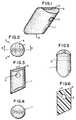
- FIG. 1 is a perspective view of a first embodiment of asuture anchor according to the invention;
- FIG. 2 is an end view of the suture anchor of FIG. 1;
- FIG. 3 is a front view of the suture anchor of FIG. 2;
- FIG. 4 is an end view of the suture anchor of FIG. 3;
- FIG. 5 is a side view of the suture anchor of FIG. 1;
- FIG. 6 is a cross-sectional view taken along line 6-6 ofFIG. 2;
- FIG. 7 is a perspective view of the suture anchor andimplantation portion of the first embodiment;
- FIG. 8 is a top view of a suture anchor extruded rodblank;
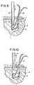
- FIG. 9 is a view of the implantation procedure of thepresent invention;
- FIG. 10 is a view of the implantation procedure uponremoval of the implantation device;
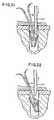
- FIGS. 11 and 12 show an alternative implantation procedurefor the device of FIG. 1;
- FIG. 13 is a perspective view of an alternate embodimentof the suture anchor of the present invention;
- FIG. 14 a-d show various embodiments of the plow edge ofthe device of the present invention;
- FIG. 15 is a top view of the suture anchor of FIG. 14;
- FIG. 16 is a front view of the suture anchor of FIG. 14;
- FIG. 17 is a cross-sectional view taken along line 17-17of FIG. 15;
- FIG. 18 is a perspective view of the suture anchor of FIG.14 with a unitized implantation device;
- FIGS. 19 through 22 show the implantation procedure of thesuture anchor;
- FIG. 23 is a perspective view of a metal suture anchoraccording to the present invention;
- FIG. 24 is a front view of a molded suture anchoraccording to the present invention;
- FIG. 25 is a front view of a molded suture anchoraccording to the present invention after implantation;
- FIG. 26 is an alternative instrument for implanting thesuture anchor of the present invention.
- FIG. 27 is a front perspective view of an alternateembodiment of the suture anchor of the present invention;
- FIG. 28 is a perspective view of an alternate embodimentof the implantation device of the present invention withsuture anchor attached;
- FIG. 29 is a perspective view of the implantation deviceof FIG. 28;
- FIG. 30 is a partial cross-sectional view showingimplantation of a suture anchor using the device of FIGS.28 and 29;
- FIG. 31 is a partial cross-sectional view showingimplantation of a suture anchor using the device of FIGS.28 and 29;
- FIG. 32 is a partial cross-sectional view showingimplantation of a suture anchor using the device of FIGS.28 29;
- FIG. 33 is an alternate embodiment of the suture anchor ofthe present invention; and,
- FIG. 34 is a partial cross-sectional view showingimplantation of the suture anchor using the device of FIG.33.
- A first aspect of a suture anchor according to the presentinvention is a unitized suture anchor, particularly asshown in FIG. 1. The first embodiment of the inventionwill now be described with reference to the Figures. Thesuture anchor 1 has a
first abutment end 2 and asecondabutment end 3. The suture anchor has a substantiallycylindrical cross-section as shown in FIG. 2 and thecylindrical longitudinal surface forms with the abutmentend 2 acorner 4. The diameter of the suture anchor issized smaller than the bore hole or opening in the bonereceiving the suture anchor. This permits passage of thesuture end(s) out of the opening. Asuture opening 5 isdefined by the body of the suture anchor 1. In analternative embodiment shown in FIG. 3 thefirst abutmentend 2 andsecond abutment end 3 are slightly tapered to apoint or edge. This is due to the extruding process offormation as will be described below. Thesuture opening 5 is formed transverse to the longitudinal direction ofthe suture anchor 1. Also thesuture opening 5 is offsetfrom the center of the suture anchor 1 such that animbalance is formed in the rotation of the device onimplantation as described below. - The suture anchor may be formed either by extrusion or byinjection molding. When injection molding the suture anchor the implantation structure of FIG. 7 is preferred.In that Figure it is seen that a
shaft 6 is formedattached to one end of the suture anchor 1. A thinnedportion forms afrangible portion 7 which will operate toseparate the suture anchor 1 from theshaft 6 uponimplantation. - Alternatively, if an extrusion process is used a rod ofmaterial is extruded as shown in FIG. 8. Diagonal cutsalong
cut lines 8 are made after boring openings 9 in therod at predetermined intervals. Thus, each of the sutureanchors is formed by the cut severing the suture body fromthe suture body of the adjacent anchor. - Now an implantation procedure will be described. Withreference to FIG. 9 the suture anchor 1 has a
suture 10passed through theopening 5. An appropriate implantationsite is created by, for example, boring a hole ofpredetermined dimension in the bone material slightlylarger than the diameter of the suture anchor. The holemay have a diameter of 5 mm for a suture anchor of 3 mmsize and is drilled through the outer cortex of the boneinto the inner cancellous layer. Upon insertion thesuture anchor is placed within the bore hole by thedownward motion as shown in FIG. 9. An upward tug on theshaft portion 6 causes a series of events to occur.Initiallycorner 4 digs into the softer cancellous layerof the bone andsecond abutment end 3 rotates intoengagement with the opposite of the wall. Thus, theanchor is wedged within the opening of the bore hole 11.Theshaft 6 separates from the suture anchor 1 by thebreaking offrangible portion 7. This leaves the sutureanchor 1 implanted within the bone while theshaft 6 is removed. This securely implants the anchor within thebone material permitting attachment of soft tissue orother materials through the use ofsuture 10. - An alternative arrangement for implantation is shown inFIGS. 11 and 12. This arrangement may have the suturealready in place such that a preloaded anchor andapparatus is provided. The apparatus includes a
tube 12which may be formed to receive therein the suture anchor1. Thesuture 10 is preloaded through theopening 5defined in the suture anchor and passed up through thetubular portion to apull tab 13. An appropriate borehole 11 is prepared in the bone and the suture anchor andtube are inserted therein. The suture anchor is permittedto drop out of the tubular portion and becomes slightlydislocated with respect to the tube.End 14 of the tubeis cut at a slight angle in order to promote the rotationof the suture anchor in a particular direction. Forexample, as shown in FIGS. 11 and 12, the suture anchor ispromoted to rotate in a clockwise direction by the longerportion of the tube being on the left side of the figure,that is the longer side of the suture anchor. Once thesuture anchor has dropped out of thetube 12, thepull tab 13 is used to snug up the suture anchor within theopening. By pulling upward on the pull tab, the biasingforce of the offset hole acting through the pulling forceof the suture firmly anchors the suture within theopening. At this point, the pull tab may be removed andthe suture slid from within thetubular portion 12. - An embodiment will now be described with reference toFIGS. 13-26. The
suture anchor 100 has abody 101 formedin a substantially truncated wedge shape. Thebody 101 defines asuture opening 102 which is rounded at itsopenings in order to avoid the likelihood of abrasion tothe suture. Anabutment wall 103 may be straight but inthe preferred embodiment is provided with a radiusedsurface which extends in an oblique direction of theanchor. This radius is set to match the radius of thebore hole into which the anchor is intended to beinserted. For example a 4 mm diameter hole would bedrilled to receive an anchor with a 4 mm radius toabutment wall 103. Aplow wall 104 forms anedge 105 atits intersection withtop 106 of the device. Theplowwall 104 is also radiused in order to maximize contactbetweenedge 105 and the wall of the bore hole to improvethe action of thecorner 105 as both a plow and africtional engagement mechanism for the anchor. - The corner or edge 105 may be formed in a plurality ofmanners. For example, the edge 105 (FIG. 14A may bestraight and squared off at the junction between
walls edge 105 may be formed with a plurality ofteeth 105B to provide additional digging force. Also, theembodiment of FIG. 14B may be modified as shown in FIG.14C to provide but a single tooth or point which wouldinitiate the digging effect of theedge 105C to introducethe remainder of the edge into the soft cancellous layer.Finally, an additional alternative embodiment is shown inFIG. 14D wherein theedge 105 is actually apoint 105D andtheplow wall 104 is actually an edge such that the bodyof the anchor has a substantially conical or cylindricalcross section. - FIG. 18 shows a
shaft 107 that extends from the top of thesuture anchor prior to insertion of the device into the bore hole. Theshaft 107 has formed thereinfrangibleportion 108 in this case formed by a pair of intersectingwebs 109. This structure is preferred in the unitizedinjection molded form of the device as it providesstability between the shaft and suture anchor bymaximizing the area moment of inertia of the cross-sectionwhile still maintaining a weakness to separationpermitting fracture at the frangible portion by minimizingthe cross-sectional area. - A stop is provided in order to locate the device in aninsertion apparatus prior to implantation. The entiredevice is injection molded out of a polymer material. Theangles of junction for the
abutment wall 103 and the top106 range from about 60° to about 140° and is preferablyabout 105°. The angle forcorner 105 at the juncture ofplow wall 104 and top 106 ranges from about 20° to about90° and preferably about 55°. - The anchors of the present invention may be made fromeither conventional bioabsorbable materials orconventional non-absorbable materials, combinationsthereof and equivalents thereof. Examples of absorbablematerials include homopolymers and copolymers of lactide,glycolide, trimethylene carbonate, caprolactone, and p-dioxanoneand blends or other combinations thereof andequivalent thereof. Of particular utility are thepolylactides, especially poly[L(-)lactide], and thelactide-rich lactide/glycolide copolymers, especially 95/5poly[L(-)lactide-co-glycolide].
- Examples of non-absorbable materials from which the sutureanchors of the present invention may be made include metallic biocompatible materials including stainlesssteel, Nitinol, titanium, Vitalium and equivalentsthereof, polymeric materials such as non-absorbablepolyesters, polyamides, polyolefins, polyurethanes, andpolyacetals and equivalents thereof.
- The bonding of the anchors of the present invention tobone may be advantageously increased by promoting bonegrowth. This can be accomplished by having a microporoussurface into which the bone can rapidly grow to aidfixation. This may be particularly advantageous in thecase of a metallic anchor, especially a titanium ortitanium alloy anchor, but may also provide benefit in thecase of polymeric anchors of the present invention,especially those made of absorbable materials. Othermethods include the coating of the anchor's surface witha substance to promote adhesion to the bone. Suchcoatings include the hydroxyapatite-containing-glasscoatings described by Ishikawa, et al., in the article"Effect of Hydroxyapatite Containing Glass Coating on theBonding between Bone and Titanium Implants" appearing inClinical Materials,
Volume 14, 1993, pages 277-285. - It is further noted that the anchors of the presentinvention can be made to contain growth factors,especially bone growth factors, that can advantageouslyincrease the effectiveness of the anchors, especially inthe area of fixation. This may be accomplished in anumber of ways, including via coatings or, in the case ofabsorbable materials by incorporating the growth factorswithin the device and allowing them to diffuse out.
- The suture anchor devices of the present invention, whenmade from an absorbable material, are preferablymanufactured by molding using conventional injectionmolding equipment and conventional injection moldingprocesses. A typical molding process includes the stepsof (1) injecting a suitable polymer melt into anappropriately designed mold or cavity at processconditions conventionally employed for such polymersystems, (2) releasing from the mold, after the melt coolsin the mold, polymer shaped in the proper configuration tomeet the design criteria of the device. Additionally theanchor molded from the absorbable polymeric material, maybe advantageously subjected to an annealing process toincrease its mechanical or biological performance.Thermal annealing can also be used to increase thedimensional stability of molded parts by increasing thecrystallinity levels in the parts. One or more surgicalsutures, or one or more sutures with surgical needlesattached, may be used in combination with the sutureanchor and may be assembled prior to sterilization. Thedevice can then be sterilized using conventional methodsto render the anchor suitable for surgical applications.
- Referring now to FIGS. 19 and 20 the implantationprocedure is displayed. Referring to FIG. 19 the
sutureanchor 100 withshaft 107 attached thereto is insertedinto a bore hole after threading of a suture 111 throughsuture opening 102. The device is inserted gently intothe bore hole until the suture anchor bottoms out in thehole as shown in FIG. 19. It is not desired to bottom outthe suture anchor. After full insertion or bottoming outthe applier (of the type in FIGS. 28 and 29), the shaft isdrawn upward forcing theedge 105 to dig into the softer cancellous layer of the bone. The edge digging in onwithdrawal of the shaft creates a rotation of the body ofthe suture anchor which, in combination with thewithdrawal tension, breaks thefrangible portion 108 andpermits removal of theshaft 107 after separation. Thesuture anchor itself rotates fully untilabutment wall 103is engaged firmly against the surface of thehole 112formed in the bone. In this case thecorner 105 is formedat about a 40° angle between the top 106 and theplow wall 104. Further,abutment wall 103 and top 106 meet to forman angle of about 105°. The top has a length of about 4.6millimeters and the abutment wall has a length of about3.2 millimeters andplow wall 104 has a length of about3.6 millimeters. These dimensions while specific to thisembodiment are proportional in all sizes of the sutureanchor being used. That is, a larger suture anchor ismade by merely proportionally increasing the dimensionswhile maintaining the angular relationship of the sides,walls and top in the same configuration. As can be seenin FIGS. 21 and 22, this embodiment can be supplied in alonger version which will require a deeper hole. - An alternative embodiment as shown in FIG. 23 wherein thebody 101A is formed of a metal substance such as atitanium alloy. Preferably the alloy is Ti-6Al-4V alloy.The metal body 101A has a
similar suture opening 102defined therein. Anabutment wall 103 and plowwall 104are provided as in the polymer version of the device andtheplow wall 104 forms acorner 105 with the top in asimilar fashion. The metal version is provided with apolymer shaft 107 havingfrangible portion 108 as isprovided in the previous embodiment. The metal body 101Ais inserted into an injection mold andshaft 107 formed by injection molding the shaft into the metal body 101A. Twointersecting openings are formed (FIG. 23A) to provide avolume to be filled with polymer. The remainder of themetal device is substantially similar to the device of theprevious description. - The
shaft 107 of the metal version of the anchor may bemade of any suitable biocompatible material such asmedical grade polymers and may be a bioabsorbable materialsuch as poly[L(-)lactide]. - FIGS. 24 and 25 show the rotational movement of the
body 101 of the suture anchor upon implantation. Thisrotational movement provides torsional forces to thefrangible portion 108 of theshaft 107 to promote thefracture of the shaft at the frangible location. - A novel insertion mechanism is shown in FIG. 26. The
applicator 113 has ascrew handle 114 havingthreads 115formed thereon. The screw handle is adjusted by rotationagainst the spring force ofspring 116. Once positioned,the screw handle is locked in place usinglocking ring 117, which is threaded down tightly against the backsurface of theapplicator 113. Ashaft 118 extends fromthe screw handle 114 along the length of theapplicator 113. The shaft has a wedgedend 119 which is receivedsubstantially within atubular portion 120 of theapplicator. The device may be used in an open procedure.But,tubular portion 120 permits optional insertion of theapplicator into a trocar for arthroscopic surgery. - The wedged
end 119 is extended from within thetubularportion 120 by the rotation of screw handle 114 to permit extension of theshaft 118 and in particular, thewedgeend 119 out of thetubular portion 120. Theshaft 107 ofthe suture anchor is inserted into thetubular portion 120until the stop 110 seats firmly against thetubularportion 120 of theapplicator 113. At this point thescrew handle is threaded in the opposite direction inorder to draw thewedge end 119 within the tubularportion. The wedging or caming effect of thewedge end 119 firmly grasps theshaft 107 of the suture anchor andholds it within the device. - A
finger 121 extends from the end oftubular portion 120and seats along the top surface of the suture anchor inorder to stabilize the body. This prevents prematurerotation of the suture anchor and fracture of thefrangible portion prior to complete insertion. The fingertranslates along the longitudinal portion of the tube inresponse to motion oftrigger 122. Upon use the device isinserted into a trocar in order to provide accessarthroscopically to the surgical site. The suture anchoris placed into the previously bored bore hole and trigger122 is manipulated. The manipulation oftrigger 122 movesthefinger 121 in the longitudinal direction. This forcesrotation of the suture anchor body and promotes thefracture of the frangible portion of the shaft whileholding the anchor in position. Simultaneously withmanipulating thefinger 121 the device is withdrawn thuscompleting the fracture of the frangible portion of theshaft. The previously threaded suture is then used toattach soft tissue according to known surgical procedures. - Referring now to Fig. 27, an alternate and preferredembodiment is shown. The body of the suture anchor is shaped as described above, however a mounting
opening 130is provided at,one end of the body of the device. Thisopening is sized to receive the mountingend 131 of theinsertion device shown in Figs. 28 and 29. Theinsertiondevice 132 having mountingend 131 is comprised of anelongated shaft 133. The shaft has two sections, anarrower distal section and a wider proximal sectionseparated by atransitional section 134. Thetransitionalsection 134 is conical in shape for reasons which will bedescribed below in connection with the implantationprocedure. Ahandle 135 is provided at the proximal endof the insertion device to facilitate gripping of thedevice during the implantation procedure. - In use, (Figs. 30 and 31)
insertion end 131 is receivedwithin mountingopening 130 of the body of the sutureanchor as shown in Figs. 28 and 29. Mountingopening 130is offset from the center line of the body of the sutureanchor for reasons which will become apparent below.During the insertion procedure the suture anchor isinserted into a previously-formed bore hole. Theinsertion tool travels in a position off axis from thehole in the bone. Once thetransition portion 134 reachesthe top of the bore hole the transition surface forces theinsertion tool towards the axis of the bore hole (i.e.,the transition portion causes the tool to center). Thiscauses the distal end of the tool to flex slightly andprovides additional torque to the suture anchor assistingthe plow edge in digging into the bone. A pair ofslots 137 are provided to permit the protected passage of thesuture out of the bore. Upon removal of the insertiontool, (Fig. 32) the flex of the tool forces the plow edgeof the suture anchor into the soft cancellous portion of the bone and the distal tip of the insertion tool slipsout of the mountingopening 130 due to the upward forceprovided on the insertion tool. This provides an extraimpetus to the insertion of the suture anchor and itsfinal implantation and mounting. - In an alternative embodiment the insertion tool may beprovided with a
distal end 136 of a soft polymer materialhaving therein a stiffening member such as a metal wire orpolymer of more rigid material. Thus, a soft andmanipulable insertion tool is provided having theresilience at the distal end to provide the insertionforces described above. The softer polymer insertion toolaids in producing a friction fit between the distal tip ofthe insertion tool and the mountingopening 130. Thus, amore sure grip is provided between the tool and the bodyof the suture anchor. - In general the mounting
opening 130 need not becylindrical in shape. The mounting opening and distal tipof the insertion tool may be shaped so as to preventrotation of the suture anchor about the tip. - A further embodiment developed for single piece polymeranchors is shown in Figs. 33 and 34. The anchor hassubstantially the same shape as the anchors describedabove, however a
protuberance 138 extends from the topsurface of the wedge. This protuberance has formedtherein the mountingopening 130 which receives theinsertion tool described above as shown in Fig. 34. Thisprotuberance provides an area for defining the mountingopening 130 such that the opening is not formed within thebody of the wedge, possibly weakening the wedge. - Thus, the invention has been described with reference tothe attached drawings. It is easily understood by one ofordinary skill in the art that changes may be made to theembodiments described herein without exceeding thescope of the attached claims.
Claims (28)
- An implantable apparatus (1) for wedging within an opening formed within a bonecomprising a body having a longitudinal cross-section defined by a perimeter, said cross-sectionbeing a quadrilateral shape and, said perimeter forming at least one biting edge (4),said body further defining a hole (5) through said body,characterised in that the holeextends through said body in a direction transverse to said cross-section.
- The apparatus (1) according to claim 1, wherein said body perimeter is in the shapeof a trapezoid.
- The apparatus (1) according to claim 1, wherein said body perimeter is in the shapeof a parallelogram.
- The apparatus (1) according to any one of the preceding claims, wherein theperimeter is defined by four sides and two of the sides diverge in a direction away fromsaid hole (5).
- The apparatus (1) according to claim 4, wherein said two of the sides have alongitudinal extent and are rounded transverse to said longitudinal extent.
- The apparatus (1) of claim 5, wherein said two sides are rounded to a radiusapproximately equal to a radius of the opening formed within the bone.
- The apparatus (1) according to claim 4, 5 or 6 wherein at least one of said sides issubstantially planar.
- The apparatus (1) according to claim 7, wherein at least one of said sides isrounded.
- The apparatus (1) according to any one of the preceding claims, wherein said holeis nearer to one side than it is to a noncontiguous second side.
- The apparatus (1) according to any one of the preceding claims, wherein said bitingedge (105) forms at least one engaging tooth (105C).
- The apparatus (1) according to claim 10, wherein said biting edge forms a pluralityof biting teeth (105B).
- The apparatus (1) according to any one of the preceding claims wherein said hole(5) has received therein a suture (10).
- The apparatus (1) according to claim 12, wherein said suture (10) has at least twofree ends extending from said body.
- The apparatus (1) according to any one of the preceding claims, wherein theapparatus (1) is presented in a sterile condition prior to use.
- The apparatus (1) according to claim 1, wherein said perimeter is formed of threemutually adjacent sides.
- The apparatus (1) according to any one of the preceding claims, further including athin longitudinal stem portion (6) extending from said body.
- The apparatus (1) according to claim 16, wherein said stem (6) is integral with andformed of the same material as said body.
- The apparatus (1) according to claim 16 or 17, wherein said body is of a medicalgrade material and said stem (6) is of a different medical grade material.
- The apparatus (1) according to claim 16, 17 or 18, wherein said stem (6) isconnected to said body by a frangible portion (7).
- The apparatus (1) according to claim 19, wherein said frangible portion (7) isformed of at least two intersecting web portions (109) forming a cross.
- The apparatus (1) according to any one of claims 16 to 20 further including aprotrusion on said stem (107) for positioning of said stem within an implantationapparatus.
- The apparatus (1) according to any one of claims 1 to 21, wherein an inserter (132)is attached to said body and said inserter (132) has an upper portion (133) and a lowerportion (131) and said upper portion (133) is of a diameter larger than a diameter of saidlower portion (131) and a transition zone (134) extends between said upper portion (133)and lower portion (134) for positioning said body within an opening during animplantation procedure.
- The apparatus (1) according to claim 22, wherein said inserter (132) further definesat least one longitudinally extending slot (137) in the upper portion at about the transitionzone (134) for passage of a suture (10) to prevent damage during the insertion process.
- The apparatus (1) according to any one of claims 16 to 23, wherein said body ismade of a medical grade metal material and said stem is made of a bioabsorbable polymer.
- The apparatus (1) according to any one of claims 1 to 23, wherein the body materialis made of a bioabsorbable material.
- The apparatus (1) according to any one of claims 1 to 23, wherein the body materialis made of a biocompatible metal.
- The apparatus (1) according to any one of claims 1 to 23 or claim 25, wherein saidbody is made of a medical grade polymer.
- The apparatus (1) according to any one of claims 22, 23, 24 or 26, wherein saidbody is formed of a metal and said inserter is received through friction fit in hole definedin one end of said body.
Applications Claiming Priority (2)
| Application Number | Priority Date | Filing Date | Title |
|---|---|---|---|
| US08/235,737US5683418A (en) | 1994-04-29 | 1994-04-29 | Wedge shaped suture anchor and method of implantation |
| US235737 | 1994-04-29 |
Publications (3)
| Publication Number | Publication Date |
|---|---|
| EP0684013A2 EP0684013A2 (en) | 1995-11-29 |
| EP0684013A3 EP0684013A3 (en) | 1996-07-31 |
| EP0684013B1true EP0684013B1 (en) | 2003-06-18 |
Family
ID=22886717
Family Applications (1)
| Application Number | Title | Priority Date | Filing Date |
|---|---|---|---|
| EP95302922AExpired - LifetimeEP0684013B1 (en) | 1994-04-29 | 1995-04-28 | Wedge shaped suture anchor |
Country Status (8)
| Country | Link |
|---|---|
| US (1) | US5683418A (en) |
| EP (1) | EP0684013B1 (en) |
| JP (1) | JP3696293B2 (en) |
| AU (1) | AU705335B2 (en) |
| BR (1) | BR9501862A (en) |
| CA (1) | CA2148063C (en) |
| DE (1) | DE69531083T2 (en) |
| ZA (1) | ZA953468B (en) |
Cited By (1)
| Publication number | Priority date | Publication date | Assignee | Title |
|---|---|---|---|---|
| US7217280B2 (en) | 1993-09-20 | 2007-05-15 | Bartlett Edwin C | Apparatus and method for anchoring sutures |
Families Citing this family (142)
| Publication number | Priority date | Publication date | Assignee | Title |
|---|---|---|---|---|
| US5868789A (en)* | 1997-02-03 | 1999-02-09 | Huebner; Randall J. | Removable suture anchor apparatus |
| US5961538A (en) | 1996-04-10 | 1999-10-05 | Mitek Surgical Products, Inc. | Wedge shaped suture anchor and method of implantation |
| US5718717A (en) | 1996-08-19 | 1998-02-17 | Bonutti; Peter M. | Suture anchor |
| US6264676B1 (en) | 1996-11-08 | 2001-07-24 | Scimed Life Systems, Inc. | Protective sheath for transvaginal anchor implantation devices |
| US6053935A (en) | 1996-11-08 | 2000-04-25 | Boston Scientific Corporation | Transvaginal anchor implantation device |
| US5782864A (en)* | 1997-04-03 | 1998-07-21 | Mitek Surgical Products, Inc. | Knotless suture system and method |
| US5885294A (en)* | 1997-09-22 | 1999-03-23 | Ethicon, Inc. | Apparatus and method for anchoring a cord-like element to a workpiece |
| JP3389075B2 (en)* | 1997-10-01 | 2003-03-24 | 株式会社東芝 | Method for manufacturing semiconductor device |
| US5894921A (en) | 1997-10-07 | 1999-04-20 | Ethicon, Inc. | Package for suture anchor |
| FR2769206B1 (en)* | 1997-10-07 | 2002-09-06 | Numedic | MULTI-APPLICATION ANCHOR FOR FIXING A WIRE ELEMENT IN A HOLLOW OR FULL BODY TO BE EQUIPPED |
| FR2771621A1 (en)* | 1997-11-28 | 1999-06-04 | Eos Medical | Impact driver for surgical bone implants |
| US6096041A (en) | 1998-01-27 | 2000-08-01 | Scimed Life Systems, Inc. | Bone anchors for bone anchor implantation device |
| US6660010B2 (en) | 1998-01-27 | 2003-12-09 | Scimed Life Systems, Inc. | Bone anchor placement device with recessed anchor mount |
| US6045551A (en) | 1998-02-06 | 2000-04-04 | Bonutti; Peter M. | Bone suture |
| US6146406A (en) | 1998-02-12 | 2000-11-14 | Smith & Nephew, Inc. | Bone anchor |
| WO1999058074A2 (en) | 1998-05-12 | 1999-11-18 | Scimed Life Systems, Inc. | Manual bone anchor placement devices |
| US6482210B1 (en) | 1998-11-12 | 2002-11-19 | Orthopaedic Biosystems, Ltd., Inc. | Soft tissue/ligament to bone fixation device with inserter |
| US6045573A (en)* | 1999-01-21 | 2000-04-04 | Ethicon, Inc. | Suture anchor having multiple sutures |
| US9521999B2 (en) | 2005-09-13 | 2016-12-20 | Arthrex, Inc. | Fully-threaded bioabsorbable suture anchor |
| US8343186B2 (en) | 2004-04-06 | 2013-01-01 | Arthrex, Inc. | Fully threaded suture anchor with transverse anchor pin |
| AU2003204842B2 (en)* | 1999-03-02 | 2005-10-06 | Edwin Clary Bartlett | Suture Anchor and Associated Method of Implantation |
| US6306158B1 (en)* | 1999-03-02 | 2001-10-23 | Edwin C. Bartlett | Suture anchor and associated method of implantation |
| US6689153B1 (en) | 1999-04-16 | 2004-02-10 | Orthopaedic Biosystems Ltd, Inc. | Methods and apparatus for a coated anchoring device and/or suture |
| DE19923487B4 (en)* | 1999-05-21 | 2005-07-21 | Teleflex Automotive Germany Gmbh | Abutment with molding for attaching control cables |
| US7235074B1 (en)* | 1999-07-09 | 2007-06-26 | Sklar Joseph H | Ligament shim |
| US6368343B1 (en) | 2000-03-13 | 2002-04-09 | Peter M. Bonutti | Method of using ultrasonic vibration to secure body tissue |
| US6447516B1 (en) | 1999-08-09 | 2002-09-10 | Peter M. Bonutti | Method of securing tissue |
| US8128698B2 (en) | 1999-10-20 | 2012-03-06 | Anulex Technologies, Inc. | Method and apparatus for the treatment of the intervertebral disc annulus |
| US7615076B2 (en) | 1999-10-20 | 2009-11-10 | Anulex Technologies, Inc. | Method and apparatus for the treatment of the intervertebral disc annulus |
| US8632590B2 (en) | 1999-10-20 | 2014-01-21 | Anulex Technologies, Inc. | Apparatus and methods for the treatment of the intervertebral disc |
| US7004970B2 (en) | 1999-10-20 | 2006-02-28 | Anulex Technologies, Inc. | Methods and devices for spinal disc annulus reconstruction and repair |
| US6524317B1 (en) | 1999-12-30 | 2003-02-25 | Opus Medical, Inc. | Method and apparatus for attaching connective tissues to bone using a knotless suture anchoring device |
| US6635073B2 (en) | 2000-05-03 | 2003-10-21 | Peter M. Bonutti | Method of securing body tissue |
| JP2001283470A (en)* | 2000-03-31 | 2001-10-12 | Pioneer Electronic Corp | System and method for recording information |
| EP1665991B1 (en) | 2000-06-05 | 2017-12-13 | Boston Scientific Limited | Devices for the treatment of urinary continence |
| US6652561B1 (en) | 2000-10-13 | 2003-11-25 | Opus Medical, Inc | Method and apparatus for attaching connective tissues to bone using a perforated suture anchoring device |
| WO2006130693A2 (en) | 2005-06-01 | 2006-12-07 | Arthrocare Corporation | Knotless suture anchoring device having deforming section to accommodate sutures of various diameters |
| US6770076B2 (en) | 2001-02-12 | 2004-08-03 | Opus Medical, Inc. | Method and apparatus for attaching connective tissues to bone using a knotless suture anchoring device |
| DE60223502T2 (en) | 2001-03-09 | 2008-11-13 | Boston Scientific Ltd., St. Michael | MEDICAL SLING |
| US8915927B2 (en) | 2001-03-09 | 2014-12-23 | Boston Scientific Scimed, Inc. | Systems, methods and devices relating to delivery of medical implants |
| US7364541B2 (en) | 2001-03-09 | 2008-04-29 | Boston Scientific Scimed, Inc. | Systems, methods and devices relating to delivery of medical implants |
| US9149261B2 (en) | 2001-03-09 | 2015-10-06 | Boston Scientific Scimed, Inc. | Systems, methods and devices relating to delivery of medical implants |
| JP4181410B2 (en) | 2001-03-09 | 2008-11-12 | ボストン サイエンティフィック リミテッド | System and method for implanting an implant |
| US8033983B2 (en) | 2001-03-09 | 2011-10-11 | Boston Scientific Scimed, Inc. | Medical implant |
| US6547800B2 (en) | 2001-06-06 | 2003-04-15 | Opus Medical, Inc. | Method and apparatus for attaching connective tissues to bone using a cortical bone anchoring device |
| US6773436B2 (en)* | 2001-09-28 | 2004-08-10 | Depuy Mitek, Inc. | Absorbable bone anchor |
| US6645227B2 (en) | 2001-11-21 | 2003-11-11 | Stryker Endoscopy | Suture anchor |
| US6719765B2 (en) | 2001-12-03 | 2004-04-13 | Bonutti 2003 Trust-A | Magnetic suturing system and method |
| US6780198B1 (en) | 2001-12-06 | 2004-08-24 | Opus Medical, Inc. | Bone anchor insertion device |
| US6855157B2 (en) | 2002-02-04 | 2005-02-15 | Arthrocare Corporation | Method and apparatus for attaching connective tissues to bone using a knotless suture anchoring device |
| US9155544B2 (en) | 2002-03-20 | 2015-10-13 | P Tech, Llc | Robotic systems and methods |
| US6843799B2 (en) | 2002-03-25 | 2005-01-18 | Edwin C. Bartlett | Suture anchor system and associated method |
| US7131973B2 (en) | 2002-05-16 | 2006-11-07 | Boston Scientific Scimed, Inc. | Bone anchor implantation device |
| US7637384B2 (en)* | 2002-08-09 | 2009-12-29 | Crown Packaging Technology, Inc. | Tamper evident closure with locking band and container therefor |
| CA2705609C (en) | 2002-08-14 | 2016-10-25 | Boston Scientific Limited | Systems, methods and devices relating to delivery of medical implants |
| AU2003259834A1 (en) | 2002-12-17 | 2004-07-29 | Boston Scientific Limited | Spacer for sling delivery system |
| US7497864B2 (en) | 2003-04-30 | 2009-03-03 | Marctec, Llc. | Tissue fastener and methods for using same |
| US7862584B2 (en)* | 2003-05-07 | 2011-01-04 | Anpa Medical, Inc. | Suture lock |
| US8109968B2 (en)* | 2003-05-07 | 2012-02-07 | Anpa Medical, Inc. | Suture lock |
| US8133257B2 (en)* | 2003-06-27 | 2012-03-13 | Depuy Mitek, Inc. | Bioabsorbable suture anchor system for use in small joints |
| US7713285B1 (en) | 2003-07-02 | 2010-05-11 | Biomet Sports Medicine, Llc | Method and apparatus for suture anchors with a vertical eyelet |
| US7942897B2 (en)* | 2003-07-10 | 2011-05-17 | Boston Scientific Scimed, Inc. | System for closing an opening in a body cavity |
| US7361138B2 (en) | 2003-07-31 | 2008-04-22 | Scimed Life Systems, Inc. | Bioabsorbable casing for surgical sling assembly |
| US7780701B1 (en) | 2003-08-13 | 2010-08-24 | Biomet Sports Medicine, Llc | Suture anchor |
| US8545386B2 (en) | 2003-08-14 | 2013-10-01 | Boston Scientific Scimed, Inc. | Surgical slings |
| DE602004023314D1 (en) | 2003-08-14 | 2009-11-05 | Boston Scient Ltd | SURGICAL SLINGS |
| US7713187B2 (en)* | 2003-10-03 | 2010-05-11 | Boston Scientific Scimed, Inc. | Systems and methods for delivering a medical implant to an anatomical location in a patient |
| US7682374B2 (en) | 2003-10-21 | 2010-03-23 | Arthrocare Corporation | Knotless suture lock and bone anchor implant method |
| EP1696803B1 (en)* | 2003-11-17 | 2016-09-28 | Boston Scientific Limited | Systems relating to associating a medical implant with a delivery device |
| US7357810B2 (en) | 2003-12-18 | 2008-04-15 | Ethicon, Inc. | High strength suture with absorbable core and suture anchor combination |
| US7914538B2 (en) | 2004-06-28 | 2011-03-29 | Depuy Mitek, Inc. | Suture anchor inserter |
| US20060074422A1 (en)* | 2004-09-27 | 2006-04-06 | Story Brooks J | Suture anchor and void filler combination |
| US20060178702A1 (en)* | 2005-02-10 | 2006-08-10 | Inion Ltd. | Apparatus for attaching sutures |
| US20060184201A1 (en)* | 2005-02-17 | 2006-08-17 | James Jervis E | Suture retainer with suture guide and method of using a suture retainer with a suture guide |
| US20090216334A1 (en)* | 2005-02-23 | 2009-08-27 | Small Bone Innovations, Inc. | Bone Implants |
| FR2887756B1 (en)* | 2005-07-01 | 2007-09-21 | Spinevision Sa | INSTRUMENT FOR MOVING A VERTEBRA |
| EP1762186B1 (en) | 2005-09-12 | 2011-02-16 | Arthrex, Inc. | Suture anchor with eyelet |
| US20070162124A1 (en)* | 2005-12-19 | 2007-07-12 | Whittaker Gregory R | Arthroscopic implants with integral fixation devices and method for use |
| US7615061B2 (en) | 2006-02-28 | 2009-11-10 | Arthrocare Corporation | Bone anchor suture-loading system, method and apparatus |
| US8133258B2 (en) | 2006-08-03 | 2012-03-13 | Arthrocare Corporation | Method and apparatus for attaching connective tissues to bone using a knotless suture anchoring device |
| US8137381B2 (en) | 2007-04-25 | 2012-03-20 | Arthrocare Corporation | Knotless suture anchor having discrete polymer components and related methods |
| US7963972B2 (en) | 2007-09-12 | 2011-06-21 | Arthrocare Corporation | Implant and delivery system for soft tissue repair |
| US8771314B2 (en) | 2007-09-28 | 2014-07-08 | Ethicon, Inc. | Surgical anchor device |
| US20090105767A1 (en)* | 2007-10-18 | 2009-04-23 | Inbone Technologies, Inc. | Total joint subsidence protector |
| US8052719B2 (en)* | 2008-04-01 | 2011-11-08 | Lonnie Paulos | Suture anchoring assemblies and methods of use |
| US20090281581A1 (en) | 2008-05-06 | 2009-11-12 | Berg Jeffery H | Method and device for securing sutures to bones |
| US8105343B2 (en) | 2008-06-30 | 2012-01-31 | Arthrocare Corporation | Independent suture tensioning and snaring apparatus |
| US8163022B2 (en) | 2008-10-14 | 2012-04-24 | Anulex Technologies, Inc. | Method and apparatus for the treatment of the intervertebral disc annulus |
| US20100121355A1 (en) | 2008-10-24 | 2010-05-13 | The Foundry, Llc | Methods and devices for suture anchor delivery |
| US8449573B2 (en) | 2008-12-05 | 2013-05-28 | Boston Scientific Scimed, Inc. | Insertion device and method for delivery of a mesh carrier |
| US8845725B2 (en)* | 2009-04-17 | 2014-09-30 | Lumaca Orthopaedics Pty Ltd | Tenodesis system |
| US8968334B2 (en) | 2009-04-17 | 2015-03-03 | Boston Scientific Scimed, Inc. | Apparatus for delivering and anchoring implantable medical devices |
| WO2010132310A1 (en) | 2009-05-12 | 2010-11-18 | Foundry Newco Xi, Inc. | Methods and devices to treat diseased or injured musculoskeletal tissue |
| US20100292733A1 (en) | 2009-05-12 | 2010-11-18 | Foundry Newco Xi, Inc. | Knotless suture anchor and methods of use |
| CA2713309C (en) | 2009-08-20 | 2013-07-02 | Howmedica Osteonics Corp. | Flexible acl instrumentation, kit and method |
| US9301750B2 (en)* | 2009-11-03 | 2016-04-05 | Boston Scientific Scimed, Inc. | Device and method for delivery of mesh-based devices |
| US8652153B2 (en) | 2010-01-11 | 2014-02-18 | Anulex Technologies, Inc. | Intervertebral disc annulus repair system and bone anchor delivery tool |
| EP2433571B1 (en) | 2010-09-23 | 2022-09-28 | Tornier, Inc. | System for bone anchor inserter depth indication |
| US9271714B2 (en) | 2011-01-21 | 2016-03-01 | Syntorr, Inc. | Methods and devices for anchoring suture in bone |
| US8795334B2 (en) | 2011-01-28 | 2014-08-05 | Smith & Nephew, Inc. | Tissue repair |
| US9131936B2 (en)* | 2011-06-10 | 2015-09-15 | Ethicon, Inc. | Anchor tip orientation device and method |
| US9636101B2 (en) | 2011-09-01 | 2017-05-02 | Arthrocare Corporation | Bone anchor having an integrated stress isolator |
| US8784426B2 (en) | 2011-10-03 | 2014-07-22 | Smith & Nephew, Inc. | Double-loop endobutton, ovoid tunnel guide, and method of ACL re-construction using the ovoid tunnel guide and the double-loop endobutton |
| US9445803B2 (en) | 2011-11-23 | 2016-09-20 | Howmedica Osteonics Corp. | Filamentary suture anchor |
| US9173657B2 (en) | 2011-12-15 | 2015-11-03 | Ethicon Endo-Surgery, Inc. | Devices and methods for endoluminal plication |
| US9113868B2 (en) | 2011-12-15 | 2015-08-25 | Ethicon Endo-Surgery, Inc. | Devices and methods for endoluminal plication |
| US9198649B2 (en) | 2012-01-27 | 2015-12-01 | Arthrocare Corporation | Rotating locking member suture anchor and method for soft tissue repair |
| US9023083B2 (en) | 2012-01-27 | 2015-05-05 | Arthrocare Corporation | Method for soft tissue repair with free floating suture locking member |
| US9364210B2 (en) | 2012-01-27 | 2016-06-14 | Arthrocare Corporation | Biased wedge suture anchor and method for soft tissue repair |
| US9034014B2 (en) | 2012-01-27 | 2015-05-19 | Arthrocare Corporation | Free floating wedge suture anchor for soft tissue repair |
| US9226742B2 (en) | 2012-01-27 | 2016-01-05 | Arthrocare Corporation | Restricted wedge suture anchor and method for soft tissue repair |
| US9084597B2 (en) | 2012-03-09 | 2015-07-21 | Smith & Nephew, Inc. | Suture-based knotless repair |
| US8992547B2 (en) | 2012-03-21 | 2015-03-31 | Ethicon Endo-Surgery, Inc. | Methods and devices for creating tissue plications |
| US9855028B2 (en) | 2012-04-06 | 2018-01-02 | Arthrocare Corporation | Multi-suture knotless anchor for attaching tissue to bone and related method |
| US20140039552A1 (en) | 2012-08-03 | 2014-02-06 | Howmedica Osteonics Corp. | Soft tissue fixation devices and methods |
| US8986327B2 (en) | 2012-10-18 | 2015-03-24 | Smith & Nephew, Inc. | Flexible anchor delivery system |
| US10179012B2 (en) | 2013-01-28 | 2019-01-15 | Cartiva, Inc. | Systems and methods for orthopedic repair |
| US9737294B2 (en) | 2013-01-28 | 2017-08-22 | Cartiva, Inc. | Method and system for orthopedic repair |
| US9402620B2 (en) | 2013-03-04 | 2016-08-02 | Howmedica Osteonics Corp. | Knotless filamentary fixation devices, assemblies and systems and methods of assembly and use |
| US9788826B2 (en) | 2013-03-11 | 2017-10-17 | Howmedica Osteonics Corp. | Filamentary fixation device and assembly and method of assembly, manufacture and use |
| US9463013B2 (en) | 2013-03-13 | 2016-10-11 | Stryker Corporation | Adjustable continuous filament structure and method of manufacture and use |
| US10292694B2 (en) | 2013-04-22 | 2019-05-21 | Pivot Medical, Inc. | Method and apparatus for attaching tissue to bone |
| US10610211B2 (en) | 2013-12-12 | 2020-04-07 | Howmedica Osteonics Corp. | Filament engagement system and methods of use |
| US9986992B2 (en) | 2014-10-28 | 2018-06-05 | Stryker Corporation | Suture anchor and associated methods of use |
| US10568616B2 (en) | 2014-12-17 | 2020-02-25 | Howmedica Osteonics Corp. | Instruments and methods of soft tissue fixation |
| US10258401B2 (en) | 2015-07-17 | 2019-04-16 | Kator, Llc | Transosseous guide |
| US9962174B2 (en) | 2015-07-17 | 2018-05-08 | Kator, Llc | Transosseous method |
| US10820918B2 (en) | 2015-07-17 | 2020-11-03 | Crossroads Extremity Systems, Llc | Transosseous guide and method |
| US12383253B2 (en) | 2015-08-04 | 2025-08-12 | Crossroads Extremity Systems, Llc | Suture anchor |
| US10226243B2 (en) | 2015-08-04 | 2019-03-12 | Kator, Llc | Transosseous suture anchor |
| US10058393B2 (en) | 2015-10-21 | 2018-08-28 | P Tech, Llc | Systems and methods for navigation and visualization |
| EP3383281B1 (en) | 2015-12-04 | 2024-01-24 | Crossroads Extremity Systems, LLC | Devices for anchoring tissue |
| USD902405S1 (en) | 2018-02-22 | 2020-11-17 | Stryker Corporation | Self-punching bone anchor inserter |
| US11944288B2 (en) | 2020-04-29 | 2024-04-02 | Coloplast A/S | Tissue anchor system including a fixation device and a delivery tool |
| USD980424S1 (en) | 2020-04-29 | 2023-03-07 | Coloplast A/S | Tissue anchor |
| US11389154B1 (en) | 2021-04-08 | 2022-07-19 | Integrity Orthopaedics, Inc. | Knotless micro suture anchor array for high density anatomical attachment of soft tissue to bone |
| US11375995B1 (en) | 2021-04-08 | 2022-07-05 | Integrity Orthopaedics, Inc. | Locking suture construct for tensioned suture to suture stitches in anchor arrays for attaching soft tissue to bone |
| US11382613B1 (en) | 2021-04-08 | 2022-07-12 | Integrity Orthopaedics, Inc. | Methods for transtendinous implantation of knotless micro suture anchors and anchor arrays |
| US11375992B1 (en) | 2021-04-08 | 2022-07-05 | Integrity Orthopaedics, Inc. | Cartridge device for suture anchor and suture management during implantation of a micro suture anchor array |
| US12226307B2 (en) | 2021-04-08 | 2025-02-18 | Integrity Orthopaedics, Inc. | Individually lockable cinch loop micro suture anchor array for high density anatomical attachment of soft tissue to bone |
| US12396839B2 (en) | 2021-04-08 | 2025-08-26 | Integrity Orthopaedics, Inc. | Method and apparatus for creating a seam-like anatomical low creep attachment of soft tissue to bone |
| US11382611B1 (en) | 2021-04-08 | 2022-07-12 | Integrity Orthopaedics, Inc. | Knotless micro-suture anchors and anchor arrays for anatomical attachment of soft tissue to bone |
Family Cites Families (17)
| Publication number | Priority date | Publication date | Assignee | Title |
|---|---|---|---|---|
| US4669473A (en)* | 1985-09-06 | 1987-06-02 | Acufex Microsurgical, Inc. | Surgical fastener |
| US4898156A (en)* | 1987-05-18 | 1990-02-06 | Mitek Surgical Products, Inc. | Suture anchor |
| US4946468A (en)* | 1989-06-06 | 1990-08-07 | Mitek Surgical Products, Inc. | Suture anchor and suture anchor installation tool |
| US5102421A (en)* | 1990-06-14 | 1992-04-07 | Wm. E. Anpach, III | Suture anchor and method of forming |
| US5269809A (en)* | 1990-07-02 | 1993-12-14 | American Cyanamid Company | Locking mechanism for use with a slotted suture anchor |
| US5224946A (en)* | 1990-07-02 | 1993-07-06 | American Cyanamid Company | Bone anchor and method of anchoring a suture to a bone |
| US5258016A (en)* | 1990-07-13 | 1993-11-02 | American Cyanamid Company | Suture anchor and driver assembly |
| ATE174777T1 (en)* | 1990-09-25 | 1999-01-15 | Innovasive Devices Inc | BONE FIXATION DEVICE |
| US5085661A (en)* | 1990-10-29 | 1992-02-04 | Gerald Moss | Surgical fastener implantation device |
| US5203787A (en)* | 1990-11-19 | 1993-04-20 | Biomet, Inc. | Suture retaining arrangement |
| DE4106823C1 (en)* | 1991-03-04 | 1992-06-25 | Liebscher Kunststofftechnik, 8032 Graefelfing, De | |
| US5207679A (en)* | 1991-09-26 | 1993-05-04 | Mitek Surgical Products, Inc. | Suture anchor and installation tool |
| US5174087A (en)* | 1992-02-19 | 1992-12-29 | Mitek Surgical Products, Inc. | Suture anchor assembly packaging system |
| US5423860A (en)* | 1993-05-28 | 1995-06-13 | American Cyanamid Company | Protective carrier for suture anchor |
| US5540718A (en)* | 1993-09-20 | 1996-07-30 | Bartlett; Edwin C. | Apparatus and method for anchoring sutures |
| US5405359A (en)* | 1994-04-29 | 1995-04-11 | Pierce; Javi | Toggle wedge |
| US5464425A (en)* | 1994-02-23 | 1995-11-07 | Orthopaedic Biosystems, Ltd. | Medullary suture anchor |
- 1994
- 1994-04-29USUS08/235,737patent/US5683418A/ennot_activeExpired - Lifetime
- 1995
- 1995-04-27CACA002148063Apatent/CA2148063C/ennot_activeExpired - Fee Related
- 1995-04-28AUAU17787/95Apatent/AU705335B2/ennot_activeCeased
- 1995-04-28ZAZA953468Apatent/ZA953468B/enunknown
- 1995-04-28DEDE69531083Tpatent/DE69531083T2/ennot_activeExpired - Lifetime
- 1995-04-28BRBR9501862Apatent/BR9501862A/ennot_activeIP Right Cessation
- 1995-04-28EPEP95302922Apatent/EP0684013B1/ennot_activeExpired - Lifetime
- 1995-04-28JPJP12753395Apatent/JP3696293B2/ennot_activeExpired - Fee Related
Non-Patent Citations (1)
| Title |
|---|
| ISHIKAWA ET AL.: "Effect of Hydroxyapatite Containing Glass Coatting on the Bonding between Bone and Titanium Implants", CLINICAL MATERIALS, no. 14, 1993, pages 277 - 285* |
Cited By (1)
| Publication number | Priority date | Publication date | Assignee | Title |
|---|---|---|---|---|
| US7217280B2 (en) | 1993-09-20 | 2007-05-15 | Bartlett Edwin C | Apparatus and method for anchoring sutures |
Also Published As
| Publication number | Publication date |
|---|---|
| BR9501862A (en) | 1995-11-21 |
| JPH0852155A (en) | 1996-02-27 |
| CA2148063C (en) | 2005-11-08 |
| EP0684013A3 (en) | 1996-07-31 |
| AU1778795A (en) | 1996-01-18 |
| DE69531083D1 (en) | 2003-07-24 |
| JP3696293B2 (en) | 2005-09-14 |
| CA2148063A1 (en) | 1995-10-30 |
| EP0684013A2 (en) | 1995-11-29 |
| ZA953468B (en) | 1996-10-28 |
| US5683418A (en) | 1997-11-04 |
| DE69531083T2 (en) | 2004-04-29 |
| AU705335B2 (en) | 1999-05-20 |
Similar Documents
| Publication | Publication Date | Title |
|---|---|---|
| EP0684013B1 (en) | Wedge shaped suture anchor | |
| US6270518B1 (en) | Wedge shaped suture anchor and method of implantation | |
| AU682111B2 (en) | Umbrella-shaped suture anchor device with actuating ring member | |
| EP0673624B1 (en) | Two-piece suture anchor with barbs | |
| USRE36289E (en) | Umbrella shaped suture anchor device with actuating ring member | |
| CA2179026C (en) | Suture anchor device | |
| CA2499694C (en) | Wedge shaped suture anchor and method of implantation | |
| AU714928B2 (en) | Wedge shaped suture anchor and method of implantation | |
| AU730640B2 (en) | Wedge shaped suture anchor and method of implantation | |
| CA2510095C (en) | Inserter for suture anchor | |
| AU775314B2 (en) | A bone anchor system | |
| CA2512262C (en) | Wedge shaped suture anchor and method of implantation | |
| CA2613279C (en) | Wedge shaped suture anchor and method of implantation | |
| CA2547742C (en) | Wedge shaped suture anchor and method of implantation |
Legal Events
| Date | Code | Title | Description |
|---|---|---|---|
| PUAI | Public reference made under article 153(3) epc to a published international application that has entered the european phase | Free format text:ORIGINAL CODE: 0009012 | |
| AK | Designated contracting states | Kind code of ref document:A2 Designated state(s):DE FR GB IT | |
| PUAL | Search report despatched | Free format text:ORIGINAL CODE: 0009013 | |
| AK | Designated contracting states | Kind code of ref document:A3 Designated state(s):DE FR GB IT | |
| 17P | Request for examination filed | Effective date:19970109 | |
| 17Q | First examination report despatched | Effective date:20000925 | |
| GRAG | Despatch of communication of intention to grant | Free format text:ORIGINAL CODE: EPIDOS AGRA | |
| RTI1 | Title (correction) | Free format text:WEDGE SHAPED SUTURE ANCHOR | |
| GRAG | Despatch of communication of intention to grant | Free format text:ORIGINAL CODE: EPIDOS AGRA | |
| GRAH | Despatch of communication of intention to grant a patent | Free format text:ORIGINAL CODE: EPIDOS IGRA | |
| GRAH | Despatch of communication of intention to grant a patent | Free format text:ORIGINAL CODE: EPIDOS IGRA | |
| GRAA | (expected) grant | Free format text:ORIGINAL CODE: 0009210 | |
| RIN1 | Information on inventor provided before grant (corrected) | Inventor name:THAL, RAYMOND Inventor name:ROSENMAN, DANIEL C. Inventor name:BRUKER, IZI Inventor name:PEDLICK, JACK S. Inventor name:JAMIOLKOWSKI, DENNIS D. Inventor name:LUSCOMBE, BRIAN H. | |
| AK | Designated contracting states | Designated state(s):DE FR GB IT | |
| REG | Reference to a national code | Ref country code:GB Ref legal event code:FG4D | |
| REF | Corresponds to: | Ref document number:69531083 Country of ref document:DE Date of ref document:20030724 Kind code of ref document:P | |
| ET | Fr: translation filed | ||
| PLBE | No opposition filed within time limit | Free format text:ORIGINAL CODE: 0009261 | |
| STAA | Information on the status of an ep patent application or granted ep patent | Free format text:STATUS: NO OPPOSITION FILED WITHIN TIME LIMIT | |
| 26N | No opposition filed | Effective date:20040319 | |
| PGFP | Annual fee paid to national office [announced via postgrant information from national office to epo] | Ref country code:DE Payment date:20130508 Year of fee payment:19 Ref country code:GB Payment date:20130424 Year of fee payment:19 | |
| PGFP | Annual fee paid to national office [announced via postgrant information from national office to epo] | Ref country code:IT Payment date:20130419 Year of fee payment:19 Ref country code:FR Payment date:20130625 Year of fee payment:19 | |
| REG | Reference to a national code | Ref country code:DE Ref legal event code:R119 Ref document number:69531083 Country of ref document:DE | |
| GBPC | Gb: european patent ceased through non-payment of renewal fee | Effective date:20140428 | |
| REG | Reference to a national code | Ref country code:FR Ref legal event code:ST Effective date:20141231 | |
| PG25 | Lapsed in a contracting state [announced via postgrant information from national office to epo] | Ref country code:GB Free format text:LAPSE BECAUSE OF NON-PAYMENT OF DUE FEES Effective date:20140428 Ref country code:DE Free format text:LAPSE BECAUSE OF NON-PAYMENT OF DUE FEES Effective date:20141101 | |
| REG | Reference to a national code | Ref country code:DE Ref legal event code:R119 Ref document number:69531083 Country of ref document:DE Effective date:20141101 | |
| PG25 | Lapsed in a contracting state [announced via postgrant information from national office to epo] | Ref country code:FR Free format text:LAPSE BECAUSE OF NON-PAYMENT OF DUE FEES Effective date:20140430 | |
| PG25 | Lapsed in a contracting state [announced via postgrant information from national office to epo] | Ref country code:IT Free format text:LAPSE BECAUSE OF NON-PAYMENT OF DUE FEES Effective date:20140428 |