EP0682955A1 - Device for drying and buffering aerosols - Google Patents
Device for drying and buffering aerosolsDownload PDFInfo
- Publication number
- EP0682955A1 EP0682955A1EP94107770AEP94107770AEP0682955A1EP 0682955 A1EP0682955 A1EP 0682955A1EP 94107770 AEP94107770 AEP 94107770AEP 94107770 AEP94107770 AEP 94107770AEP 0682955 A1EP0682955 A1EP 0682955A1
- Authority
- EP
- European Patent Office
- Prior art keywords
- base body
- pipe section
- aerosol
- axis
- connecting piece
- Prior art date
- Legal status (The legal status is an assumption and is not a legal conclusion. Google has not performed a legal analysis and makes no representation as to the accuracy of the status listed.)
- Granted
Links
- 239000000443aerosolSubstances0.000titleclaimsabstractdescription70
- 238000001035dryingMethods0.000titleclaimsabstractdescription12
- 230000003139buffering effectEffects0.000titleclaimsdescription9
- 238000002664inhalation therapyMethods0.000claimsabstractdescription5
- 230000015572biosynthetic processEffects0.000claimsdescription9
- 238000002347injectionMethods0.000claimsdescription4
- 239000007924injectionSubstances0.000claimsdescription4
- 239000000463materialSubstances0.000claimsdescription2
- 230000000694effectsEffects0.000abstractdescription5
- 239000002245particleSubstances0.000description22
- 238000007654immersionMethods0.000description14
- 230000008021depositionEffects0.000description7
- 239000000126substanceSubstances0.000description7
- 239000004480active ingredientSubstances0.000description6
- 239000003814drugSubstances0.000description6
- 229940079593drugDrugs0.000description6
- 238000002663nebulizationMethods0.000description5
- 238000000034methodMethods0.000description4
- 210000000214mouthAnatomy0.000description4
- 239000000843powderSubstances0.000description4
- 239000007788liquidSubstances0.000description3
- 210000004072lungAnatomy0.000description3
- 238000004519manufacturing processMethods0.000description3
- 238000000926separation methodMethods0.000description3
- 239000000243solutionSubstances0.000description3
- 238000000889atomisationMethods0.000description2
- 239000011248coating agentSubstances0.000description2
- 238000000576coating methodMethods0.000description2
- 238000010276constructionMethods0.000description2
- 238000009826distributionMethods0.000description2
- 239000003595mistSubstances0.000description2
- 239000003380propellantSubstances0.000description2
- 230000000241respiratory effectEffects0.000description2
- 210000002345respiratory systemAnatomy0.000description2
- 239000000725suspensionSubstances0.000description2
- 244000089486Phragmites australis subsp australisSpecies0.000description1
- 238000010521absorption reactionMethods0.000description1
- 230000002411adverseEffects0.000description1
- 238000007664blowingMethods0.000description1
- 238000007600chargingMethods0.000description1
- 239000003795chemical substances by applicationSubstances0.000description1
- 238000004140cleaningMethods0.000description1
- 230000001419dependent effectEffects0.000description1
- 230000006866deteriorationEffects0.000description1
- 238000007786electrostatic chargingMethods0.000description1
- 238000000265homogenisationMethods0.000description1
- 238000002483medicationMethods0.000description1
- 239000006199nebulizerSubstances0.000description1
- 230000029058respiratory gaseous exchangeEffects0.000description1
- 208000023504respiratory system diseaseDiseases0.000description1
- 150000003839saltsChemical class0.000description1
- 229920006395saturated elastomerPolymers0.000description1
- 238000004062sedimentationMethods0.000description1
- 239000007787solidSubstances0.000description1
- 239000002904solventSubstances0.000description1
- 125000006850spacer groupChemical group0.000description1
- 239000007921spraySubstances0.000description1
- 238000004659sterilization and disinfectionMethods0.000description1
- 230000009885systemic effectEffects0.000description1
- 238000002560therapeutic procedureMethods0.000description1
Images


Classifications
- A—HUMAN NECESSITIES
- A61—MEDICAL OR VETERINARY SCIENCE; HYGIENE
- A61M—DEVICES FOR INTRODUCING MEDIA INTO, OR ONTO, THE BODY; DEVICES FOR TRANSDUCING BODY MEDIA OR FOR TAKING MEDIA FROM THE BODY; DEVICES FOR PRODUCING OR ENDING SLEEP OR STUPOR
- A61M15/00—Inhalators
- A61M15/0086—Inhalation chambers
- A—HUMAN NECESSITIES
- A61—MEDICAL OR VETERINARY SCIENCE; HYGIENE
- A61M—DEVICES FOR INTRODUCING MEDIA INTO, OR ONTO, THE BODY; DEVICES FOR TRANSDUCING BODY MEDIA OR FOR TAKING MEDIA FROM THE BODY; DEVICES FOR PRODUCING OR ENDING SLEEP OR STUPOR
- A61M11/00—Sprayers or atomisers specially adapted for therapeutic purposes
- A61M11/06—Sprayers or atomisers specially adapted for therapeutic purposes of the injector type
- A—HUMAN NECESSITIES
- A61—MEDICAL OR VETERINARY SCIENCE; HYGIENE
- A61M—DEVICES FOR INTRODUCING MEDIA INTO, OR ONTO, THE BODY; DEVICES FOR TRANSDUCING BODY MEDIA OR FOR TAKING MEDIA FROM THE BODY; DEVICES FOR PRODUCING OR ENDING SLEEP OR STUPOR
- A61M2205/00—General characteristics of the apparatus
- A61M2205/02—General characteristics of the apparatus characterised by a particular materials
- A61M2205/0233—Conductive materials, e.g. antistatic coatings for spark prevention
- A—HUMAN NECESSITIES
- A61—MEDICAL OR VETERINARY SCIENCE; HYGIENE
- A61M—DEVICES FOR INTRODUCING MEDIA INTO, OR ONTO, THE BODY; DEVICES FOR TRANSDUCING BODY MEDIA OR FOR TAKING MEDIA FROM THE BODY; DEVICES FOR PRODUCING OR ENDING SLEEP OR STUPOR
- A61M2206/00—Characteristics of a physical parameter; associated device therefor
- A61M2206/10—Flow characteristics
- A61M2206/16—Rotating swirling helical flow, e.g. by tangential inflows
Definitions
- the inventionrelates to a device for drying and / or buffering aerosols for inhalation therapy.
- Inhalation therapyis used not only for the treatment of respiratory diseases, but increasingly also for the administration of other medical agents for systemic application.
- the active ingredientis mixed with air as a fine mist so that it can be inhaled. It is important here that the particles containing the active ingredient are very small (below 5 ⁇ m) in order to ensure that they are carried into the lungs by the respiratory flow and are not already separated out in the mouth and throat. Effective and rapid absorption of the active ingredient is only possible in the lungs. The separation of larger particles in the mouth or throat can also lead to undesirable local side effects with certain medications.
- wet aerosolsare understood to mean those aerosols that are generated by atomizing a liquid in which the active ingredient is dissolved or dispersed, if appropriate together with a carrier substance, for example a salt.
- a carrier substancefor example a salt.
- fine dropletsare formed, which are in the starting aerosol, i.e. immediately after the aerosol has been generated, with the aid of a nozzle or the like. still have a size distribution in which only one certain proportion of the droplets are respirable.
- the aerosolcan be dried, which reduces the size of the individual particles. This treatment of the starting aerosol contributes significantly to the properties of the aerosol that the patient inhales.
- an inhalation vessel made of plasticis known from DE 89 08 273 U1, on the amphora-like base body opposite an inlet and an outlet connection are provided on the two end faces.
- the amphora-like shapegives the starting aerosol the opportunity to spread and calm down, which is also accompanied by drying.
- the known inhalation vesselfulfills the buffering requirements, i.e. the provision of a supply of breathable aerosol. Due to separation and incomplete removal of the inhalation vessel, not inconsiderable parts of the aerosol and thus the medication are lost.
- Another device for treating aerosolsis known from EP 0 504 459 A1; the device has a cylindrical nebulization chamber with a supply and a removal nozzle, both of which are arranged tangentially in the vicinity of one of the end faces on the lateral surface of the cylindrical nebulization chamber.
- the arrangement of the two nozzlescreates a spiral vortex that runs around the longitudinal axis of the nebulization chamber.
- Its designcan also be supported by a core part, which is arranged in the nebulizing space coaxially with the cylindrical nebulizing space.
- the feed nozzlecan be formed by a helical surface in the Area of one end of the nebulizing space are replaced, which initiates the formation of the spiral vortex when the starting aerosol is diffused.
- the known devicethere is sufficient buffering of breathable aerosol with simultaneous homogenization and drying.
- the volumeis suitable for emptying with one breath.
- the aerosol particlestend to separate on the inner wall of the nebulization chamber, in particular due to inertial forces of the wet aerosol immediately after the nozzle emerges or if the speed of rotation is increased by strong breaths and the centrifugal forces become too great.
- a device of similar constructionis described in WO 90/15635; however, this device is used to atomize particles of an inhalation drug already in powder form.
- the drugis supplied to the device as a dry aerosol, namely as a fine mist of the powder particles.
- a dry aerosolnamely as a fine mist of the powder particles.
- EP 0 504 459 A1is the generation of a sufficiently large centrifugal force which brings about further comminution of the particles and thus atomization by the particles colliding with one another and onto the nebuliser inner wall.
- a device known from US 3,362,405works, in which a powdery substance, which is located at the bottom of a cylindrical container, is whirled up and even more finely ground, ie atomized, by the particles colliding with one another and with the container wall becomes.
- the deviceis not used for buffering, but for producing a dry aerosol that is simply released into the environment.
- the generation and deliveryare continuous and not dependent on a user's breathing.
- the vortex flow required for the centrifugal forcesis brought about by blowing air into the cylindrical container via a pipe arranged tangentially on the lateral surface of the cylinder.
- the swirled material particlesare crushed by colliding with one another and by wall impaction and, together with the air carrying them, get out of the cylindrical container through a tube which is provided in the center of the end face of the cylinder, in the vicinity of which there is also the connection piece for the supply air.
- the structure and function of the deviceare reminiscent of the basic principle of a separator known as a "cyclone", since large particles of the pulverulent substance are separated again.
- While one group of the devices described aboveis suitable for treating a wet aerosol, the other group of devices is not suitable for this purpose.
- improvementsare desirable in the devices suitable for treating a wet aerosol, in particular a targeted influencing of the aerosol particle size.
- the improved devicesshould be suitable for powder-based aerosols; furthermore, a deposition of aerosol particles and a deterioration in the degree of evacuation of all aerosol types is to be avoided.
- the inventionis therefore based on the object of providing a device for drying and / or buffering aerosols with which the properties of the aerosol, in particular the particle size in the case of wet aerosols, can be influenced in a targeted manner, in which the deposition of aerosol particles is avoided and which can basically be completely removed by one breath.
- the inventioncleverly uses the two vortexes already known from the cyclone separator, which are formed in one another. This process is explained in more detail in the description of the exemplary embodiments of the invention. So far, however, a sufficiently high rotational speed and thus a high centrifugal force have always been striven for, the device according to the invention is essentially characterized in that, due to the lower speed, the outer vortex causes a shield that prevents aerosol particles from reaching the vessel wall on the one hand and Rinses the container and thus ensures very good removal of the aerosol.
- the inventionproposes the use of a device reminiscent of a cyclone separator in construction, which is provided by the central supply of the aerosol from one end face and the breath-controlled removal of the aerosol at the on the other end of the rotationally symmetrical, preferably cylindrical base body, with the formation of the two spiral vortices lying one inside the other, allowing targeted drying of wet aerosols, deposition on the inner wall being virtually avoided.
- the aerosolis generated by a dispersing nozzle which is introduced into a tapered part of the cylindrical device.
- a solution and / or suspensionis mixed with dry air and sprayed axially into the device.
- the operating parameters of the nozzlesuch as dispersing air humidity, dispersing air throughput and liquid mass flow, are matched to the dimensions of the device in such a way that minimal impact at the opposite end of the device takes place (the air change when filling the vessel corresponds to only about 80% of the volume) and that a certain average droplet size can be achieved by drying in the dispersing air.
- the total volume of the deviceis matched to the average tidal volume of a patient so that the device can be easily cleared in one breath. Two preferred embodiments therefore each have a volume of 570 ml (for adults) or 350 ml (for ten-year-old children).
- the pressurized solution or suspensionis injected into the device in a short burst through a single-substance nozzle, the air contained in the device not being saturated with solvent (propellant gas), so that drying can take place. Due to the short burst of spray, the volume and length of the device can be further reduced or shortened in this case. This embodiment then has a volume of approximately 240 ml.
- the device shown in Fig. 1consists of a cylindrical base body 1 which tapers at a first end in the form of a truncated cone 1a.
- the smaller opening of the truncated cone 1a with a diameter D2is designed for the connection of a dispersing nozzle 2.
- the nozzle 2is used in a sealed manner, for example with an O-ring (not shown) and has an injection direction coaxial to the axis of symmetry 1-L of the cylindrical base body 1.
- a pipe section 3is introduced through a hole in the surface 4 closing this end face coaxially to the axis of rotation 1-L of the base body 1, the pipe section 3 protruding into the base body 1 by a defined length L3.
- a tangentially opening pipe section 5is attached to the side of the second end 1b of the base body 1 and serves to supply supply air with formation of eddies around the axis of rotation 1-L of the base body 1.
- a medication solutionis mixed with dry air in the dispersing nozzle 2 and the starting aerosol thus produced is sprayed centrally along the axis of symmetry 1-L of the base body 1.
- Fig. 2shows how the upward aerosol jet causes air to flow down the vessel wall. The sum of these flows leads to ring vortices which have their axis of rotation perpendicular to the axis of symmetry 1-L of the base body 1. These vortices lead to an efficient distribution of the aerosol and at the same time calm it down because kinetic energy is extracted from the aerosol particles. This brings the aerosol into balance and the particles dry to the desired size after a short time.
- the nozzle 2is constructed in such a way that the aerosol close to the dip tube 3 already follows the vortexes described above in order to exclude the impact at the upper end 1b of the basic vessel 1 as a result of inertial forces, as a result of which deposition of the aerosol at this point is largely avoided.
- the aerosolcan be exhaled via the immersion tube 3.
- a mouthpiece(not shown) directly onto the immersion tube and, if possible, to mount this in a straight extension of the immersion tube 3 in order to avoid deposition losses.
- the dip tube 3conveys the suction created by exhaling to the basic vessel 1, as a result of which supply air flows in via the tangential pipe section 5.
- the tangential feed 5 coupled to the central immersion tube 3leads to the formation of cyclone vortices which screw downward about the axis of rotation of the base body 1 along the vessel wall, as shown in FIG. 2.
- the aerosolis forced toward the center of the vessel 1 to a diameter which corresponds approximately to that of the immersion tube 3, and is slightly rotated by air friction. Because the flow velocities caused by inhalation are small when the device is designed and designed in accordance with the invention, an excessive centrifugal effect, as described in the introduction, is prevented. Simultaneously with the formation of the cyclone vortex, the rotating aerosol column is sucked off through the immersion tube 3 and the dryer vessel 1 is finally rinsed out by incoming air. Then aerosol can be sprayed in again and a new inhalation cycle can be started.
- the devicecan be operated in all spatial positions as long as filling and exhalation follow each other in time (sedimentation of particles is negligible).
- the diameter D5 of the supply air pipe 5should preferably be chosen so that the sum of the immersion pipe diameter D3 and twice the clear width D5 of the supply air pipe is approximately equal to the diameter D1 of the dryer vessel 1.
- the opening diameter D5 of the supply air pipe 5should largely utilize the width available in addition to the immersion pipe 3. Then the circular flow around the immersion pipe 3 takes place without widening or constricting the air flow entering from the supply air pipe 5, which favors optimal flow and evacuation.
- the immersion tube 3should not be chosen any longer, since otherwise aerosol would be deposited during the injection process due to increased impaction on and in the immersion tube 5.
- the total volume of the deviceshould preferably be optimized to the tidal volume of a patient group in such a way that it can be completely cleared with one breath if possible. Based on the empirically determined average tidal volumes of 750 ml for adults and 450 ml for children around the age of 10, a preferred embodiment for adults has a total volume of 570 ml and a further embodiment for children has a volume of 350 ml.
- the supply airis supplied through a straight, tangentially opening pipe section 5.
- the direct guidance without deflection devicesresults in a minimal flow resistance, which is very important for patients with lung weakness, since this resistance has to be overcome when inhaling.
- the supply air linecould also be guided circularly on the outer wall of the second front end 1b (not shown), or a pipe section 5b opening parallel to the axis from above, could be selected, as shown in FIG. 5.
- a deflection device which increases the flow resistancewould have to be added in order to generate a tangential flow.
- 5shows a scoop-shaped guide surface 6.
- a radial supply air inlet 5ais also conceivable, as shown in FIG. 6, with an adapted deflection device 7 for generating a tangential flow.
- an inspiration valve(not shown) to the end of the supply air pipe opposite the housing mouth in order to prevent air from flowing out of the basic vessel 1 in this way. It is then important to have a sufficient length of the supply air duct so that the turbulent flow caused by the valve can be equalized again until it enters the vessel 1.
- a strongly turbulent inflow or an asymmetrical flow profilewould lower the efficiency of the device, since the formation of cyclone vortices would be adversely affected and the flow resistance would be unnecessarily increased.
- the cylindrical shape of the base body 1 in the exemplary embodimentsis the simplest Shape that enables the formation of cyclone vortices with tangential air supply.
- other rotationally symmetrical base bodiesare also conceivable, for example an overall conical course from one end 1a to the other end 1b (not shown). In this case, the entire vessel (base body 1 and end 1a) would have the shape of a truncated cone.
- an advantageous exemplary embodiment of the device shown in FIG. 1consists in manufacturing the cylindrical main body 1, the conically tapering part 1a and the opposite end 1b containing the immersion tube 3 and the supply air tube 5 as separate parts which are detachably connected to one another , e.g. by simply plugging them together. This simplifies the manufacture of the device, but also facilitates cleaning and disinfection of the device. This would also make it possible to vary the size, for example by inserting a shortened cylindrical intermediate piece, which would enable the device to be used as a compact inhalation aid for metered dose aerosols generated with a propellant gas.
Landscapes
- Health & Medical Sciences (AREA)
- Engineering & Computer Science (AREA)
- Bioinformatics & Cheminformatics (AREA)
- Pulmonology (AREA)
- Anesthesiology (AREA)
- Biomedical Technology (AREA)
- Heart & Thoracic Surgery (AREA)
- Hematology (AREA)
- Life Sciences & Earth Sciences (AREA)
- Animal Behavior & Ethology (AREA)
- General Health & Medical Sciences (AREA)
- Public Health (AREA)
- Veterinary Medicine (AREA)
- Medicinal Preparation (AREA)
- Vaporization, Distillation, Condensation, Sublimation, And Cold Traps (AREA)
- Drying Of Solid Materials (AREA)
Abstract
Description
Translated fromGermanDie Erfindung betrifft eine Vorrichtung zur Trockung und/oder Pufferung von Aerosolen für die Inhalationstherapie.The invention relates to a device for drying and / or buffering aerosols for inhalation therapy.
Die Inhalationstherapie wird nicht nur zur Behandlung von Atemwegserkrankungen, sondern in zunehmendem Maße auch zur Verabreichung anderer medizinischer Wirkstoffe für die systemische Applikation eingesetzt. Bei einer solchen Therapie wird der Wirkstoff als feiner Nebel mit Luft vermischt, um so eingeatmet werden zu können. Wichtig hierbei ist, daß die den Wirkstoff enthaltenden Partikel sehr klein sind (unter 5 µm), um zu gewährleisten, daß sie vom Atemstrom in die Lunge getragen und nicht bereits im Mund- und Rachenraum abgeschieden werden. Erst in der Lunge ist eine effektive und rasche Aufnahme des Wirkstoffs möglich. Die Abscheidung größerer Partikel in Mund oder Rachen kann bei bestimmten Medikamenten auch zu unerwünschten lokalen Nebenwirkungen führen.Inhalation therapy is used not only for the treatment of respiratory diseases, but increasingly also for the administration of other medical agents for systemic application. With such a therapy, the active ingredient is mixed with air as a fine mist so that it can be inhaled. It is important here that the particles containing the active ingredient are very small (below 5 μm) in order to ensure that they are carried into the lungs by the respiratory flow and are not already separated out in the mouth and throat. Effective and rapid absorption of the active ingredient is only possible in the lungs. The separation of larger particles in the mouth or throat can also lead to undesirable local side effects with certain medications.
Von besonderer Bedeutung sind "nasse Aerosole", worunter solche Aerosole verstanden werden, die durch Verneblung einer Flüssigkeit erzeugt werden, in der der Wirkstoff ggf. zusammen mit einer Trägersubstanz, beispielsweise einem Salz, gelöst oder dispergiert ist. Bei der Verneblung der Flüssigkeit werden feine Tröpfchen gebildet, die im Ausgangsaerosol, also unmittelbar nach der Erzeugung des Aerosols mit Hilfe einer Düse o.ä. noch eine Größenverteilung aufweisen, bei der nur ein bestimmter Anteil der Tröpfchen lungengängig ist. Um den Anteil lungengängiger Tröpfchen zu erhöhen, kann das Aerosol abgetrocknet werden, wodurch die Größe der einzelnen Partikel reduziert wird. Diese Behandlung des Ausgangsaerosols trägt entscheidend zu den letzlich erzielten Eigenschaften des Aerosols bei, das vom Patienten eingeatmet wird. Bei Aerosolen auf Pulverbasis, d.h. bei Aerosolen, die durch Zerstäubung einer pulverförmigen Ausgangssubstanz erzeugt werden, ist die Partikelgröße durch die Ausgangssubstanz festgelegt. Bei beiden Aerosoltypen ist aber die Pufferung einer ausreichenden Aerosolmenge erforderlich.Of particular importance are “wet aerosols”, which are understood to mean those aerosols that are generated by atomizing a liquid in which the active ingredient is dissolved or dispersed, if appropriate together with a carrier substance, for example a salt. When the liquid is atomized, fine droplets are formed, which are in the starting aerosol, i.e. immediately after the aerosol has been generated, with the aid of a nozzle or the like. still have a size distribution in which only one certain proportion of the droplets are respirable. To increase the proportion of respirable droplets, the aerosol can be dried, which reduces the size of the individual particles. This treatment of the starting aerosol contributes significantly to the properties of the aerosol that the patient inhales. In the case of powder-based aerosols, ie in the case of aerosols which are produced by atomizing a powdery starting substance, the particle size is determined by the starting substance. With both types of aerosol, a sufficient amount of aerosol must be buffered.
Um die Ausbildung eines Aeroslos für die Inhaltionstherapie auch der tieferen Atemwege zu unterstützen, ist aus DE 89 08 273 U1 ein Inhalationsgefäß aus Kunstoff bekannt, an dessen amphorenartigen Grundkörper gegenüberliegend an den beiden Stirnseiten ein Einlaß- und ein Auslaßstutzen vorgesehen sind. Durch die amphorenartige Form wird dem Ausgangsaerosol Gelegenheit zur Ausbreitung und Beruhigung gegeben, womit auch eine Abtrocknung einhergeht. Das bekannte Inhalationsgefäß erfüllt die Anforderungen hinsichtlich der Pufferung, d.h. der Bereitstellung eines Vorrats von atembarem Aerosol. Durch Abscheidung und unvollständige Ausräumung des Inhalationsgefäßes gehen aber nicht unerhebliche Teile des Aerosols und damit des Medikaments verloren.In order to support the formation of an aerosol for inhalation therapy also of the deeper respiratory tract, an inhalation vessel made of plastic is known from DE 89 08 273 U1, on the amphora-like base body opposite an inlet and an outlet connection are provided on the two end faces. The amphora-like shape gives the starting aerosol the opportunity to spread and calm down, which is also accompanied by drying. The known inhalation vessel fulfills the buffering requirements, i.e. the provision of a supply of breathable aerosol. Due to separation and incomplete removal of the inhalation vessel, not inconsiderable parts of the aerosol and thus the medication are lost.
Eine andere Vorrichtung zur Behandlung von Aerosolen ist aus EP 0 504 459 A1 bekannt; die Vorrichtung weist einen zylindrischen Verneblungsraum mit einem Zuführ- und einem Entnahmestutzen auf, die beide jeweils in der Nähe zu einer der Stirnseiten an der Mantelfläche des zylindrischen Verneblungsraumes tangential angeordnet sind. Durch die Anordnung der beiden Stutzen wird ein um die Längsachse des Verneblungsraumes verlaufender Spiralwirbel erzeugt. Dessen Ausbildung kann auch durch ein Kernteil unterstützt werden, das in dem Verneblungsraum koaxial mit dem zylindrischen Verneblungsraum angeordnet ist. Alternativ kann der Zuführstutzen durch eine Wendelfläche im Bereich der einen Stirnseite des Verneblungsraumes ersetzt werden, die bei diffuser Zuführung des Ausgangsaerosols die Ausbildung des Spiralwirbels einleitet. Bei der bekannten Vorrichtung erfolgt eine ausreichende Pufferung von atembarem Aerosol bei gleichzeitiger Homogenisierung und Abtrocknung. Das Volumen eignet sich zur Entleerung durch einen Atemzug. Jedoch neigen die Aerosolpartikel zur Abscheidung an der Innenwand des Verneblungsraumes, insbesondere durch Trägheitskräfte des Naßaerosols unmittelbar nach dem Düsenaustritt oder wenn durch starke Atemzüge die Rotationsgeschwindigkeit erhöht ist und die Zentrifugalkräfte zu groß werden. Neben der aus diesem Grund auftretenden Ablagerung des Wirkstoffes sind im Vernebler Bereiche vorhanden, aus denen das Aerosol nur unvollständig ausgeräumt wird. Letzlich wird durch beide Effekte eine gezielte Beeinflussung der Partikelgröße unmöglich gemacht, zumindest aber erheblich erschwert.Another device for treating aerosols is known from EP 0 504 459 A1; the device has a cylindrical nebulization chamber with a supply and a removal nozzle, both of which are arranged tangentially in the vicinity of one of the end faces on the lateral surface of the cylindrical nebulization chamber. The arrangement of the two nozzles creates a spiral vortex that runs around the longitudinal axis of the nebulization chamber. Its design can also be supported by a core part, which is arranged in the nebulizing space coaxially with the cylindrical nebulizing space. Alternatively, the feed nozzle can be formed by a helical surface in the Area of one end of the nebulizing space are replaced, which initiates the formation of the spiral vortex when the starting aerosol is diffused. In the known device there is sufficient buffering of breathable aerosol with simultaneous homogenization and drying. The volume is suitable for emptying with one breath. However, the aerosol particles tend to separate on the inner wall of the nebulization chamber, in particular due to inertial forces of the wet aerosol immediately after the nozzle emerges or if the speed of rotation is increased by strong breaths and the centrifugal forces become too great. In addition to the deposition of the active ingredient that occurs for this reason, there are areas in the nebulizer from which the aerosol is only incompletely removed. Ultimately, both effects make targeted influencing of the particle size impossible, or at least considerably more difficult.
Eine Vorrichtung ähnlichen Aufbaus ist in WO 90/15635 beschrieben; jedoch dient diese Vorrichtung zur Zerstäubung von Partikeln eines bereits in Pulverform vorliegenden Inhalationsmedikaments. Das Medikament wird als trockenes Aerosol, nämlich als feiner Nebel der Pulverpartikel, der Vorrichtung zugeführt. Im Vordergrund, und damit im Gegensatz zu EP 0 504 459 A1, steht die Erzeugung einer ausreichend großen Zentrifugalkraft, die eine weitere Zerkleinerung der Partikel und damit eine Zerstäubung durch Aufprall der Partikel aufeinander und auf die Verneblerinnenwand bewirkt.A device of similar construction is described in WO 90/15635; however, this device is used to atomize particles of an inhalation drug already in powder form. The drug is supplied to the device as a dry aerosol, namely as a fine mist of the powder particles. In the foreground, and thus in contrast to EP 0 504 459 A1, is the generation of a sufficiently large centrifugal force which brings about further comminution of the particles and thus atomization by the particles colliding with one another and onto the nebuliser inner wall.
Auf demselben Prinzip hinsichtlich der Zerstäubung beruhend, arbeitet eine aus US 3.362.405 bekannte Vorrichtung, bei der ein pulverförmiger Stoff, der sich am Boden eines zylindrischen Behälters befindet, aufgewirbelt und durch Zusammenstöße der Partikel untereinander sowie mit der Behälterwand noch feiner zerrieben, d.h. zerstäubt wird. Die Vorrichtung dient nicht zur Pufferung, sondern zur Erzeugung eines trockenen Aerosols, das einfach an die Umgebung abgegeben wird. Die Erzeugung und die Abgabe erfolgen kontinuierlich und nicht in Abhängigkeit von der Atmung eines Benutzers. Bei der bekannten Vorrichtung wird die für die Zentrifugalkräfte erforderliche Wirbelströmung hervorgerufen, indem über ein tangential an der Mantelfläche des Zylinders angeordnetes Rohr Luft in den zylindrischen Behälter eingeblasen wird. Die aufgewirbelten Stoffpartikel werden durch Aufeinanderprallen sowie durch Wandimpaktion zerkleinert und gelangen zusammen mit der sie tragenden Luft aus dem zylindrischen Behälter durch ein Rohr hinaus, das mittig in der Stirnseite des Zylinders vorgesehen ist, in deren Nähe sich auch der Stutzen für die Zuluft befindet. Die Vorrichtung erinnert in Aufbau und Funktion an das Grundprinzip eines als "Zyklon" bekannten Abscheiders, da große Partikel des pulverförmigen Stoffes wieder abgeschieden werden.Based on the same principle with regard to atomization, a device known from US 3,362,405 works, in which a powdery substance, which is located at the bottom of a cylindrical container, is whirled up and even more finely ground, ie atomized, by the particles colliding with one another and with the container wall becomes. The device is not used for buffering, but for producing a dry aerosol that is simply released into the environment. The generation and delivery are continuous and not dependent on a user's breathing. In the known device, the vortex flow required for the centrifugal forces is brought about by blowing air into the cylindrical container via a pipe arranged tangentially on the lateral surface of the cylinder. The swirled material particles are crushed by colliding with one another and by wall impaction and, together with the air carrying them, get out of the cylindrical container through a tube which is provided in the center of the end face of the cylinder, in the vicinity of which there is also the connection piece for the supply air. The structure and function of the device are reminiscent of the basic principle of a separator known as a "cyclone", since large particles of the pulverulent substance are separated again.
Während sich die eine Gruppe der zuvor beschriebenen Vorrichtungen zur Behandlung eines nassen Aerosols eignet, scheidet die andere Gruppe der Vorrichtungen für diesen Zweck aus. Bei den zur Behandlung eines nassen Aerosols geeigneten Vorrichtungen sind aber Verbesserungen wünschenswert, insbesondere eine gezielte Beeinflussung der Aerosolpartikelgröße. Selbstverständlich sollen die verbesserten Vorrichtungen für Aerosole auf Pulverbasis geeignet sein; ferner soll weiterhin eine Ablagerung von Aerosolpartikeln und eine Verschlechterung des Ausräumungsgrades bei allen Aerosolarten vermieden werden.While one group of the devices described above is suitable for treating a wet aerosol, the other group of devices is not suitable for this purpose. However, improvements are desirable in the devices suitable for treating a wet aerosol, in particular a targeted influencing of the aerosol particle size. Of course, the improved devices should be suitable for powder-based aerosols; furthermore, a deposition of aerosol particles and a deterioration in the degree of evacuation of all aerosol types is to be avoided.
Ausgehend von den zuerst beschriebenen Vorrichtungen liegt der Erfindung daher die Aufgabe zugrunde, eine Vorrichtung zur Trocknung und/oder Pufferung von Aerosolen zu schaffen, mit der die Eigenschaften des Aerosols, insbesondere bei nassen Aerosolen die Partikelgröße, gezielt beeinflußt werden kann, bei der die Ablagerung von Aerosolpartikeln vermieden wird und die grundsätzlich durch einen Atemzug vollständig ausgeräumt werden kann.Starting from the devices described first, the invention is therefore based on the object of providing a device for drying and / or buffering aerosols with which the properties of the aerosol, in particular the particle size in the case of wet aerosols, can be influenced in a targeted manner, in which the deposition of aerosol particles is avoided and which can basically be completely removed by one breath.
Gelöst wird diese Augfgabe durch eine Vorrichtung zur Trocknung und/oder Pufferung von Aerosolen mit den Merkmalen des Patentanspruchs 1. Vorteilhafte Ausgestaltungen ergeben sich aus den Unteransprüchen.This problem is solved by a device for drying and / or buffering aerosols with the features of
Die Erfindung nutzt in geschickter Weise die beiden bereits vom Zyklon-Abscheider bekannten Wirbel, die sich ineinander ausbilden. Dieser Vorgang wird bei der Schilderung der Ausführungsbeispiele der Erfindung noch genauer erläutert. Während aber bislang stets eine ausreichend hohe Rotationsgeschwindigkeit und damit eine hohe Zentrifugalkraft angestrebt wurde, zeichnet sich die erfindungsgemäße Vorrichtung im wesentlichen dadurch aus, daß aufgrund der geringeren Geschwindigkeit der äußere Wirbel eine Abschirmung bewirkt, die einerseits verhindert daß Aerosolpartikel die Gefäßwand erreichen und die anderseits den Behälter spült und damit eine sehr gute Ausräumung des Aerosols sicherstellt. Durch die Erfindung wird zur Trocknung und/oder Pufferung eines Aerosols, insbesondere eines nassen Aerosols der Einsatz einer im Aufbau an einen Zyklon-Abscheider erinnernden Vorrichtung vorgeschlagen, die durch die zentrale Zuführung des Aerosols von der einen Stirnseite und die atemzuggesteuerte Entnahme des Aerosols an der anderen Stirnseite des rotationsymmetrischen, vorzugsweise zylindrischen Grundkörpers unter Ausbildung der beiden ineinander liegenden Spiralwirbel eine gezielte Abtrocknung nasser Aerosole erlaubt, wobei eine Ablagerung an der Innenwand nahezu vermieden wird.The invention cleverly uses the two vortexes already known from the cyclone separator, which are formed in one another. This process is explained in more detail in the description of the exemplary embodiments of the invention. So far, however, a sufficiently high rotational speed and thus a high centrifugal force have always been striven for, the device according to the invention is essentially characterized in that, due to the lower speed, the outer vortex causes a shield that prevents aerosol particles from reaching the vessel wall on the one hand and Rinses the container and thus ensures very good removal of the aerosol. For drying and / or buffering an aerosol, in particular a wet aerosol, the invention proposes the use of a device reminiscent of a cyclone separator in construction, which is provided by the central supply of the aerosol from one end face and the breath-controlled removal of the aerosol at the on the other end of the rotationally symmetrical, preferably cylindrical base body, with the formation of the two spiral vortices lying one inside the other, allowing targeted drying of wet aerosols, deposition on the inner wall being virtually avoided.
In einer bevorzugten Ausführungsform wird das Aerosol erzeugt durch eine Dispergierdüse, die in einem konisch zulaufenden Teil der zylindrischen Vorrichtung eingebracht ist. In dieser Düse wird eine Lösung und/oder Suspension mit trockener Luft vermischt und axial in die Vorrichtung eingesprüht. Die Betriebsparameter der Düse wie Dispergierluftfeuchte, Dispergierluftdurchsatz und Flüssigkeitsmassenstrom sind so auf die Abmessungen der Vorrichtung abgestimmt, daß minimale Impaktion am gegenüberliegenden Ende der Vorrichtung stattfindet (der Luftwechsel beim Füllen des Gefäßes entspricht nur etwa 80% des Volumens) und daß eine bestimmte mittlere Tröpfchengröße durch die Abtrocknung in der Dispergierluft erzielt werden kann. Das Gesamtvolumen der Vorrichtung ist so auf das Durchschnitts-Atemvolumen eines Patienten abgestimmt, daß die Vorrichtung in einem Atemzug problemlos ausgeräumt werden kann. Zwei bevorzugte Ausführungsformen haben daher jeweils ein Volumen von 570 ml (für Erwachsene) bzw. 350 ml (für zehnjährige Kinder).In a preferred embodiment, the aerosol is generated by a dispersing nozzle which is introduced into a tapered part of the cylindrical device. In this nozzle, a solution and / or suspension is mixed with dry air and sprayed axially into the device. The operating parameters of the nozzle, such as dispersing air humidity, dispersing air throughput and liquid mass flow, are matched to the dimensions of the device in such a way that minimal impact at the opposite end of the device takes place (the air change when filling the vessel corresponds to only about 80% of the volume) and that a certain average droplet size can be achieved by drying in the dispersing air. The total volume of the device is matched to the average tidal volume of a patient so that the device can be easily cleared in one breath. Two preferred embodiments therefore each have a volume of 570 ml (for adults) or 350 ml (for ten-year-old children).
In einer anderen bevorzugten Ausführungsform wird die unter Druck stehende Lösung oder Suspension in einem kurzen Stoß durch eine Einstoffdüse in die Vorrichtung eingespritzt, wobei die in der Vorrichtung enthaltene Luft nicht mit Lösungsmittel (Treibgas) gesättigt ist, sodaß eine Abtrocknung stattfinden kann. Aufgrund des kurzen Sprühstoßes können in diesem Fall das Volumen und die Länge der Vorrichtung weiter verkleinert bzw. verkürzt werden. Diese Ausführungsform hat dann ein Volumen von ungefähr 240 ml.In another preferred embodiment, the pressurized solution or suspension is injected into the device in a short burst through a single-substance nozzle, the air contained in the device not being saturated with solvent (propellant gas), so that drying can take place. Due to the short burst of spray, the volume and length of the device can be further reduced or shortened in this case. This embodiment then has a volume of approximately 240 ml.
Inhaliert der Patient, so strömt durch den Sog, der über ein Tauchrohr in der der Düse gegenüberliegenden Seite der Vorrichtung auf das Aerosol im Inneren ausgeübt wird, Zuluft von oben in die Vorrichtung nach und wird dabei so geführt, daß Zyklonwirbel erzeugt werden, die an der Gefäßwand entlang in Richtung der Düse laufen. Diese Wirbel drängen das Aerosol zur Mitte des Gefäßes hin zusammen und versetzen das Aerosol in leichte Rotation. Die rotierende, innere Aerosolsäule wird dann durch das Tauchrohr abgesaugt und die Vorrichtung mit nachfließender Zuluft vollständig ausgespült. Dadurch wird eine sehr gute Ausräumung erzielt. Da die Bündelung und Führung des Aerosols allein durch Luftströmungen bewirkt wird, findet praktisch kein Aufprall auf feste Strömungsführungselemente statt, der einen Wirkstoffverlust durch Abscheidung verursachen würde.If the patient inhales, supply air flows into the device from above through the suction, which is exerted on the aerosol inside via a dip tube in the side of the device opposite the nozzle, and is guided in such a way that cyclone vortices are generated which act on run along the vessel wall in the direction of the nozzle. These vortices push the aerosol towards the center of the vessel and set the aerosol in slight rotation. The rotating, inner aerosol column is then sucked off through the immersion tube and the device is completely rinsed out with incoming air. This ensures a very good clearance. Since the bundling and guiding of the aerosol is effected solely by air currents, there is practically no impact on solid flow guiding elements which would cause loss of active ingredient through separation.
Weitere Einzelheiten und Vorteile der Erfindung ergeben sich aus der Beschreibung der in den Zeichnungen dargestellten Ausführungsbeispiele der erfindungsgemäßen Vorrichtung. Die Zeichnungen zeigen:
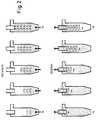
- Fig. 1 eine Perspektivansicht eines ersten, mit einer tangentialen Luftzuführung ausgestatteten Ausführungsbeispiels der erfindungsgemäßen Vorrichtung;
- Fig. 2 die Strömungsverhältnisse in der erfindungsgemäßen Vorrichtung beim Vernebelungs- bzw. Abatmungsvorgang beispielhaft an dem ersten Ausführungsbeispiel;
- Fig. 3 einen Längsschnitt durch die Vorrichtung des ersten Ausführungsbeispiels;
- Fig. 4 eine Schnittansicht des stirnseitigen Endes des ersten Ausführungsbeispiels in der Höhe des tangentialen Zuluftrohrs;
- Fig. 5 ein zweites Ausführungsbeispiel, bei dem die Zuluft über ein achsenparalleles Rohr zugeführt wird; und
- Fig. 6 ein drittes Ausführungsbeispiel, bei dem die Zuluft radial der Vorrichtung zugeführt wird.
- 1 is a perspective view of a first embodiment of the device according to the invention equipped with a tangential air supply;
- 2 shows the flow conditions in the device according to the invention during the nebulization or exhalation process, using the first embodiment as an example;
- 3 shows a longitudinal section through the device of the first embodiment;
- Figure 4 is a sectional view of the front end of the first embodiment at the level of the tangential supply air pipe.
- Fig. 5 shows a second embodiment in which the supply air is supplied via a pipe parallel to the axis; and
- Fig. 6 shows a third embodiment in which the supply air is supplied radially to the device.
Die in Fig. 1 dargestellte Vorrichtung besteht aus einem zylindrischen Grundkörper 1, der sich an einem ersten stirnseitigen Ende in Form eines Kegelstumpfs 1a verjüngt. Die kleinere Öffnung des Kegelstumpfs 1a mit einem Durchmesser D₂ ist für den Anschluß einer Dispergierdüse 2 ausgebildet. Die Düse 2 wird abgedichtet eingesetzt, z.B. mit einem O-Ring (nicht abgebildet) und hat eine zur Symmetrieachse 1-L des zylindrischen Grundkörpers 1 koaxiale Einspritzrichtung. In der zweiten Stirnseite 1b des Grundkörpers 1 ist ein Rohrstück 3 durch ein Loch in der diese Stirnseite verschließenden Fläche 4 koaxial zur Rotationsachse 1-L des Grundkörpers 1 eingebracht, wobei das Rohrstück 3 um eine definierte Länge L₃ in den Grundkörper 1 hineinragt. Seitlich an das zweite stirnseitige Ende 1b des Grundkörpers 1 ist ein tangential einmündendes Rohrstück 5 angebracht, welches der Zuführung von Zuluft unter Ausbildung von Wirbeln um die Rotationsachse 1-L des Grundkörpers 1 dient.The device shown in Fig. 1 consists of a
In der Dispergierdüse 2 wird eine Medikamentlösung mit trockener Luft vermischt und das derart erzeugte Ausgangsaerosol entlang der Symmetrieachse 1-L des Grundkörpers 1 zentral eingesprüht. Fig. 2 zeigt, wie der aufwärtsgerichtete Aerosolstrahl ein Hinabströmen von Luft entlang der Gefäßwand bewirkt. Die Summe dieser Strömungen führt zu Ring-Wirbeln, die ihre Rotationsachse senkrecht zur Symmetrieachse 1-L des Grundkörpers 1 haben. Diese Wirbel führen zu effizienter Verteilung des Aerosols und beruhigen es gleichzeitig, da den Aerosolpartikeln Bewegungsenergie entzogen wird. Dadurch kommt das Aerosol ins Gleichgewicht und die Partikel trocknen nach kurzer Zeit auf die gewünschte Größe ab. Die Düse 2 ist derart aufgebaut, daß das Aerosol nahe am Tauchrohr 3 bereits den oben beschriebenen Wirbeln strömungsmäßig folgt, um den Aufprall am oberen Ende 1b des Grundgefäßes 1 als Folge von Trägheitskräften auszuschließen, wodurch eine Ablagerung des Aerosols an dieser Stelle weitgehend vermieden wird.A medication solution is mixed with dry air in the dispersing
Nachdem das Gefäß 1 gefüllt ist, d.h. der Einspritzvorgang abgeschlossen ist, kann das Aerosol über das Tauchrohr 3 abgeatmet werden. Zu diesem Zweck ist es günstig, ein Mundstück (nicht abgebildet) direkt auf das Tauchrohr aufzustecken und dies möglichst in gerader Verlängerung des Tauchrohrs 3 anzubringen, um Abscheidungsverluste zu vermeiden. Das Tauchrohr 3 vermittelt den durch das Abatmen entstehenden Sog an das Grundgefäß 1, wodurch Zuluft über das tangentiale Rohrstück 5 zuströmt. Die tangentiale Zuführung 5 gekoppelt mit dem zentralen Tauchrohr 3 führt zur Ausbildung von Zyklonwirbeln, die sich um die Rotationsachse des Grundkörpers 1 entlang der Gefäßwand nach unten schrauben, wie in Fig. 2 abgebildet.After the
Durch diese Wirbel wird das Aerosol zur Mitte des Gefäßes 1 hin auf einen Durchmesser, der ungefähr dem des Tauchrohrs 3 entspricht, zusammengedrängt, und durch Luftreibung leicht in Rotation versetzt. Dadurch, daß die durch Einatmen bewirkten Strömungsgeschwindigkeiten bei erfindungsgemäßer Gestaltung und Auslegung der Vorrichtung klein sind, wird ein übermäßiger Zentrifugaleffekt, wie einleitend beschrieben, verhindert. Gleichzeitig mit der Ausbildung der Zyklonwirbel wird die rotierende Aerosolsäule durch das Tauchrohr 3 abgesaugt und das Trocknergefäß 1 schließlich durch nachströmende Zuluft ausgespült. Danach kann wieder Aerosol eingesprüht werden und so ein neuer Inhalationszyklus begonnen werden.By means of these vortices, the aerosol is forced toward the center of the
Die Vorrichtung kann in allen räumlichen Lagen betrieben werden, sofern Befüllung und Abatmung zeitlich dicht aufeinander folgen (Sedimentation von Partikeln vernachlässigbar).The device can be operated in all spatial positions as long as filling and exhalation follow each other in time (sedimentation of particles is negligible).
In den Fig. 3 und 4 sowie in nachstehender Tabelle sind zweckmäßige Abmessungen des in Fig. 1 dargestellten Ausführungsbeispiels veranschaulicht.
Allgemein sollte der Durchmesser D₅ des Zuluftrohrs 5 vorzugsweise so gewählt werden, daß die Summe aus dem Tauchrohrdurchmesser D₃ und zweimal der lichten Weite D₅ des Zuluftrohres ungefähr gleich dem Durchmesser D₁ des Trocknergefäßes 1 ist. Mit anderen Worten, der Öffnungsdurchmesser D₅ des Zuluftrohres 5 sollte die neben dem Tauchrohr 3 zur Verfügung stehende Breite weitgehend ausnutzen. Dann nämlich erfolgt die zirkulare Strömungsführung um das Tauchrohr 3 ohne Aufweitung oder Einengung des aus dem Zuluftrohr 5 eintretenden Luftstroms, was eine optimale Strömung und Ausräumung begünstigt. Ferner ist es vorteilhaft, die in den Trockner hineinragende Länge L₃ des Tauchrohrs 3 doppelt so groß zu wählen wie den Durchmesser D₅ des Zuluftrohrs 5, da dadurch eine besonders gute Ausbildung der Zyklonwirbel gewährleistet ist. Länger sollte das Tauchrohr 3 nicht gewählt werden, da sich sonst beim Einspritzvorgang Aerosol durch verstärkte Impaktion am und im Tauchrohr 5 niederschlagen würde.In general, the diameter D₅ of the
Das Gesamtvolumen der Vorrichtung ist vorzugsweise so auf das Atemvolumen einer Patientengruppe zu optimieren, daß sie möglichst mit einem Atemzug vollständig ausgeräumt werden kann. Aufgrund der empirisch festgestellten durchschnittlichen Atemzugvolumina von 750 ml für Erwachsene bzw. 450 ml für etwa 10jährige Kinder, hat eine bevorzugte Ausführungsform für Erwachsene ein Gesamtvolumen von 570 ml und eine weitere Ausführungsform für Kinder ein Volumen von 350 ml.The total volume of the device should preferably be optimized to the tidal volume of a patient group in such a way that it can be completely cleared with one breath if possible. Based on the empirically determined average tidal volumes of 750 ml for adults and 450 ml for children around the age of 10, a preferred embodiment for adults has a total volume of 570 ml and a further embodiment for children has a volume of 350 ml.
Bei der Spacervolumenauslegung wird ein 20 bis 30%iger Abschlag vom jeweiligen Atemzugvolumen berücksichtigt, damit die Mündhöhle und die oberen Atemwege, in denen das Aerosol keine Wirkung erzielen kann, mit Frischluft ausgewaschen werden können (z.B. 200 ml beim Erwachsenen).When designing the spacer volume, a 20 to 30% discount on the respiratory volume is taken into account, so that the oral cavity and the upper respiratory tract, in which the aerosol can have no effect, can be washed out with fresh air (e.g. 200 ml in adults).
In dem bislang beschriebenen Ausführungsbeispiel wird die Zuluft durch ein gerades, tangential einmündendes Rohrstück 5 zugeführt. Durch die direkte Führung ohne Umlenkeinrichtungen wird ein minimaler Strömungswiderstand erzielt, was bei Patienten mit einer Lungenschwäche sehr bedeutend ist, da dieser Widerstand beim Inhalieren überwunden werden muß. Es sind jedoch auch andere Ausführungsformen denkbar. So könnte, um Platz zu sparen, die Zuluftleitung auch zirkular an der Außenwand des zweiten stirnseitigen Endes 1b geführt werden (nicht abgebildet) oder auch ein achsen-parallel von oben einmündendes Rohrstück 5b gewählt werden, wie in Fig. 5 abgebildet. In letzterem Fall müßte aber zusätzlich eine den Strömungswiderstand erhöhende Umlenkeinrichtung zur Erzeugung einer tangentialen Strömung hinzugefügt werden. In Fig. 5 ist eine schaufelförmige Führungsfläche 6 abgebildet. Schließlich ist auch eine radiale Zulufteinführung 5a denkbar, wie in Fig. 6 abgebildet, mit einer angepaßten Umlenkeinrichtung 7 zur Erzeugung einer tangentialen Strömung.In the exemplary embodiment described so far, the supply air is supplied through a straight, tangentially opening
Unabhängig von der speziellen Ausgestaltung der Zuluftführung ist es vorteilhaft, an dem der Gehäusemündung entgegengesetzten Ende des Zuluftrohrs ein Inspirationsventil (nicht abgebildet) anzubringen, um ein Herausströmen von Luft aus dem Grundgefäß 1 auf diesem Wege zu verhindern. Wichtig ist dann eine ausreichende Länge der Zuluftführung, damit so die vom Ventil verursachte turbulente Strömung bis zum Eintritt in das Gefäß 1 wieder vergleichmäßigt werden kann. Eine stark turbulente Einströmung oder ein asymmetrisches Strömungsprofil würde die Effizienz der Vorrichtung senken, da die Ausbildung von Zyklonwirbeln ungünstig beeinflußt würde und der Strömungswiderstand unnötig erhöht werden würde.Regardless of the special design of the supply air duct, it is advantageous to attach an inspiration valve (not shown) to the end of the supply air pipe opposite the housing mouth in order to prevent air from flowing out of the
Der konische Zulauf des ersten stirnseitigen Endes 1a des Grundgefäßes 1, der in den Fig. 1 und 3 dargestellt ist, dient der Vermeidung von Toträumen, in denen sich Aerosol sammeln könnte ohne ausgeräumt zu werden. Die zylindrische Form des Grundkörpers 1 in den Ausführungsbeispielen ist die einfachste Form, die die Ausbildung von Zyklonwirbeln bei tangentialer Luftzuführung ermoglicht. Es sind aber auch andere rotationssymmetrische Grundkörper denkbar, so zum Beispiel ein gesamtkonischer Verlauf vom einen Ende 1a bis zum anderen Ende 1b (nicht abgebildet). In diesem Fall hätte das gesamte Gefäß (Grundkörper 1 und Ende 1a) die Form eines Kegelstumpfs.The conical inlet of the
Da durch die Reibung der strömenden Luft an der Gefäßwand der Vorrichtung eine elektrostatische Aufladung der Wand stattfinden kann, ist es vorteilhaft, das Gefäß aus einem antistatisch wirkenden Stoff zu fertigen. Die durch die Aufladung verursachten Anziehungskräfte würden eine verstärkte Ablagerung von Aerosolpartikeln an der Gefäßwand bewirken, was einen Verlust an Medikament bedeuten würde. Auch eine Beschichtung der Gefäßinnenwand mit einem antistatischen Belag ist denkbar.Since the friction of the flowing air on the vessel wall of the device can cause electrostatic charging of the wall, it is advantageous to manufacture the vessel from an antistatic substance. The attractive forces caused by the charging would cause an increased deposition of aerosol particles on the vessel wall, which would mean a loss of medication. Coating the inner wall of the vessel with an antistatic coating is also conceivable.
Schließlich besteht noch ein vorteilhaftes Ausführungsbeispiel der in Fig. 1 dargestellten Vorrichtung darin, den zylindrischen Hauptkörper 1, den sich konisch verjüngenden Teil 1a sowie das das Tauchrohr 3 und das Zuluftrohr 5 enthaltende entgegengesetzte Ende 1b als separate Teile zu fertigen, die lösbar miteinander verbunden sind, z.B. durch einfaches Zusammenstecken. Dies vereinfacht die Herstellung der Vorrichtung, erleichtert aber auch die Reinigung und Desinfektion der Vorrichtung. Auch wäre dadurch eine Variation der Größe, beispielsweise durch Einsetzen eines verkürzten zylindrischen Zwischenstücks möglich, was einen Einsatz der Vorrichtung als kompakte Inhalationshilfe für mit einem Treibgas erzeugte Dosieraerosole ermöglichen würde.Finally, an advantageous exemplary embodiment of the device shown in FIG. 1 consists in manufacturing the cylindrical
Claims (15)
Translated fromGermandadurchgekennzeichnet, daß
das Rohrstück (3) an seinem dem Grundkörper (1) abgewandten Ende mit einer Ventileinrichtung abschließt, an die sich ein Mündstück anschließt.Device according to one of claims 1 to 12,
characterized in that
the tube piece (3) at its end facing away from the base body (1) ends with a valve device to which an mouthpiece is connected.
Priority Applications (6)
| Application Number | Priority Date | Filing Date | Title |
|---|---|---|---|
| AT94107770TATE205098T1 (en) | 1994-05-19 | 1994-05-19 | DEVICE FOR DRYING AND BUFFERING AEROSOLS |
| EP94107770AEP0682955B1 (en) | 1994-05-19 | 1994-05-19 | Device for drying and buffering aerosols |
| DE59409856TDE59409856D1 (en) | 1994-05-19 | 1994-05-19 | Device for drying and buffering aerosols |
| US08/442,582US5596982A (en) | 1994-05-19 | 1995-05-17 | Apparatus for drying and buffering aerosols |
| JP7142707AJPH08266626A (en) | 1994-05-19 | 1995-05-17 | Equipment for the drying and buffering of aerosols |
| CA002149722ACA2149722A1 (en) | 1994-05-19 | 1995-05-18 | Apparatus for drying and buffering aerosols |
Applications Claiming Priority (1)
| Application Number | Priority Date | Filing Date | Title |
|---|---|---|---|
| EP94107770AEP0682955B1 (en) | 1994-05-19 | 1994-05-19 | Device for drying and buffering aerosols |
Publications (2)
| Publication Number | Publication Date |
|---|---|
| EP0682955A1true EP0682955A1 (en) | 1995-11-22 |
| EP0682955B1 EP0682955B1 (en) | 2001-09-05 |
Family
ID=8215952
Family Applications (1)
| Application Number | Title | Priority Date | Filing Date |
|---|---|---|---|
| EP94107770AExpired - LifetimeEP0682955B1 (en) | 1994-05-19 | 1994-05-19 | Device for drying and buffering aerosols |
Country Status (6)
| Country | Link |
|---|---|
| US (1) | US5596982A (en) |
| EP (1) | EP0682955B1 (en) |
| JP (1) | JPH08266626A (en) |
| AT (1) | ATE205098T1 (en) |
| CA (1) | CA2149722A1 (en) |
| DE (1) | DE59409856D1 (en) |
Cited By (6)
| Publication number | Priority date | Publication date | Assignee | Title |
|---|---|---|---|---|
| EP1010438A1 (en)* | 1998-12-11 | 2000-06-21 | Bespak Plc | Inhalation apparatus |
| WO2003089036A1 (en)* | 2002-04-19 | 2003-10-30 | 3M Innovative Properties Company | A spacer for inertial removal of the non-respirable fraction of medicinal aerosols |
| EP1743671A1 (en)* | 2005-07-13 | 2007-01-17 | La Diffusion Technique Francaise | Inhalation chamber for the storage and transport of aerosols for medicinal aerosol generating devices |
| EP2366421A1 (en)* | 2004-12-09 | 2011-09-21 | Cambridge Consultants Limited | Dry powder inhalers |
| EP2371409A1 (en)* | 2010-03-31 | 2011-10-05 | AeroSurgical Limited | Insufflation of body cavities |
| WO2011133740A1 (en)* | 2010-04-23 | 2011-10-27 | Cambridge Consultants Limited | Dry powder inhaler assembly and containers |
Families Citing this family (53)
| Publication number | Priority date | Publication date | Assignee | Title |
|---|---|---|---|---|
| IL108780A (en)* | 1993-02-27 | 1999-06-20 | Fisons Plc | Inhalation device |
| JP2002515794A (en)* | 1996-11-01 | 2002-05-28 | イー・アイ・デュポン・ドウ・ヌムール・アンド・カンパニー | Storage resistant spacers for metered dose inhalers |
| CA2212430A1 (en) | 1997-08-07 | 1999-02-07 | George Volgyesi | Inhalation device |
| US6158431A (en)* | 1998-02-13 | 2000-12-12 | Tsi Incorporated | Portable systems and methods for delivery of therapeutic material to the pulmonary system |
| US6257233B1 (en)* | 1998-06-04 | 2001-07-10 | Inhale Therapeutic Systems | Dry powder dispersing apparatus and methods for their use |
| US6260549B1 (en) | 1998-06-18 | 2001-07-17 | Clavius Devices, Inc. | Breath-activated metered-dose inhaler |
| IL126200A0 (en)* | 1998-09-14 | 1999-05-09 | Aerotron Medical Instrumentati | Nebulizer |
| GB2353222B (en) | 1999-06-23 | 2001-09-19 | Cambridge Consultants | Inhalers |
| KR20010018973A (en)* | 1999-08-24 | 2001-03-15 | 구자홍 | structure for inhalation passage of air in multi cyclone dust collector |
| US6427688B1 (en)* | 2000-02-01 | 2002-08-06 | Dura Pharmaceuticals, Icn. | Dry powder inhaler |
| CA2406185C (en) | 2000-04-11 | 2011-03-15 | Trudell Medical International | Aerosol delivery apparatus with positive expiratory pressure capacity |
| US7204245B2 (en)* | 2000-07-06 | 2007-04-17 | Clinical Technologies, Inc | Aerosol enhancement device |
| US6363932B1 (en) | 2000-07-06 | 2002-04-02 | Clinical Technologies, Inc. | Aerosol enhancement device |
| GB2364919A (en)* | 2000-07-21 | 2002-02-13 | Cambridge Consultants | Inhalers |
| GB2375308A (en)* | 2001-05-10 | 2002-11-13 | Cambridge Consultants | Inhalers |
| US20040211419A1 (en)* | 2001-05-10 | 2004-10-28 | Eason Stephen William | Inhalers |
| US20030205226A1 (en) | 2002-05-02 | 2003-11-06 | Pre Holding, Inc. | Aerosol medication inhalation system |
| US6904908B2 (en) | 2002-05-21 | 2005-06-14 | Trudell Medical International | Visual indicator for an aerosol medication delivery apparatus and system |
| FR2879465B1 (en)* | 2004-12-21 | 2008-02-15 | Diffusion Tech Francaise Sarl | AEROSOL TRANSFER DEVICE FOR MEDICAL AEROSOL GENERATORS OR SYSTEMS FOR GENERATING MEDICAL AEROSOLS |
| US8763605B2 (en) | 2005-07-20 | 2014-07-01 | Manta Devices, Llc | Inhalation device |
| EP1962805B1 (en) | 2005-12-08 | 2016-07-06 | Insmed Incorporated | Lipid-based compositions of antiinfectives for treating pulmonary infections |
| GB0616299D0 (en)* | 2006-08-16 | 2006-09-27 | Cambridge Consultants | Drug Capsules for dry power inhalers |
| US20080210225A1 (en)* | 2007-03-01 | 2008-09-04 | Rapha Institute For Health | Disposable antistatic spacer |
| US9119783B2 (en) | 2007-05-07 | 2015-09-01 | Insmed Incorporated | Method of treating pulmonary disorders with liposomal amikacin formulations |
| EP2898914B1 (en) | 2007-07-06 | 2018-06-20 | Manta Devices, LLC | Inhalation devices for storing and delivering medicament |
| US11224704B2 (en) | 2007-07-06 | 2022-01-18 | Manta Devices, Llc | Dose delivery device for inhalation |
| CA2709071C (en) | 2007-12-14 | 2016-11-15 | Labogroup S.A.S. | Delivering aerosolizable food products |
| PL2285439T3 (en) | 2008-04-04 | 2014-05-30 | Nektar Therapeutics | Aerosolization device |
| USD605283S1 (en) | 2008-04-04 | 2009-12-01 | Novartis Pharma Ag | Aerosolization device |
| US8550074B2 (en)* | 2009-01-15 | 2013-10-08 | Manta Devices, Llc | Delivery device and related methods |
| WO2011116293A2 (en) | 2010-03-19 | 2011-09-22 | Manta Devices, Llc | Delivery device and related methods |
| GB201006480D0 (en)* | 2010-04-19 | 2010-06-02 | Intersurgical Ag | Improvements relating to respiratory apparatus |
| US9757528B2 (en) | 2010-08-23 | 2017-09-12 | Darren Rubin | Nebulizer having different negative pressure threshold settings |
| EP2608829A4 (en) | 2010-08-23 | 2015-11-18 | Darren Rubin | SYSTEMS AND METHODS FOR ADMINISTERING AEROSOL WITH AIRFLOW REGULATION |
| US11103659B2 (en) | 2011-07-06 | 2021-08-31 | Manta Devices, Llc | Delivery device and related methods |
| US9649454B2 (en) | 2012-05-03 | 2017-05-16 | Manta Devices, Llc | Delivery device and related methods |
| MX369828B (en) | 2012-05-21 | 2019-11-22 | Insmed Inc | SYSTEMS TO TREAT PULMONARY INFECTIONS. |
| CN104812301B (en)* | 2012-09-25 | 2018-02-09 | 吸入科学瑞典股份公司 | exposure system |
| EP3581186A1 (en) | 2012-11-29 | 2019-12-18 | Insmed Incorporated | Stabilized vancomycin formulations |
| USD701599S1 (en)* | 2013-03-26 | 2014-03-25 | Pediatric Innovations USA, LLC | Nasal device |
| USD732659S1 (en) | 2013-03-26 | 2015-06-23 | Pediatric Innovations USA, LLC | Car-shaped nasal device |
| USD732658S1 (en) | 2013-03-26 | 2015-06-23 | Pediatric Innovations USA, LLC | Nasal device with airplane wings |
| USD701956S1 (en)* | 2013-03-26 | 2014-04-01 | Pediatric Innovations USA, LLC | Nasal device |
| US9480805B2 (en)* | 2014-02-11 | 2016-11-01 | Lloyd Courtney | Material recovery and capture device for atomized material delivery apparatuses |
| NO2709641T3 (en)* | 2014-03-10 | 2018-05-12 | ||
| EP3137140B1 (en) | 2014-05-02 | 2019-07-10 | Manta Devices, LLC | Delivery device |
| ME03536B (en) | 2014-05-15 | 2020-04-20 | Insmed Inc | Methods for treating pulmonary non-tuberculous mycobacterial infections |
| GB201512932D0 (en)* | 2015-07-22 | 2015-09-02 | Linde Ag | A Nebuliser |
| EP3524302B1 (en)* | 2018-02-08 | 2025-08-06 | Nli GmbH | Aerosol generator |
| EP3773505A4 (en) | 2018-03-30 | 2021-12-22 | Insmed Incorporated | PROCESS FOR THE CONTINUOUS MANUFACTURING OF LIPOSOMAL MEDICINAL PRODUCTS |
| JP6958950B1 (en)* | 2020-11-27 | 2021-11-02 | ニップファーマ株式会社 | Inhalation aid |
| CN116173358B (en)* | 2021-11-29 | 2025-03-28 | 康希诺生物股份公司 | A nebulizer cup and its application in nebulizer inhalation drug administration |
| CN114383918B (en)* | 2022-01-11 | 2023-06-23 | 长安大学 | A kind of ENM aerosol diffusion drying system |
Citations (8)
| Publication number | Priority date | Publication date | Assignee | Title |
|---|---|---|---|---|
| US3362405A (en) | 1964-04-06 | 1968-01-09 | Hamilton O. Hazel | Method and apparatus for admixing gas with solid particles |
| US3980074A (en)* | 1973-07-18 | 1976-09-14 | Beecham Group Limited | Device for the administration of powders |
| FR2352556A1 (en)* | 1976-05-26 | 1977-12-23 | Pasteur Institut | POWDER INHALER |
| US4155359A (en)* | 1977-05-23 | 1979-05-22 | Antoni Zagorski | Air filtering mask |
| DE8908273U1 (en) | 1989-07-07 | 1989-08-24 | Boehringer Ingelheim KG, 6507 Ingelheim | Plastic inhalation vessel |
| WO1990015635A1 (en) | 1989-06-16 | 1990-12-27 | Huhtamäki Oy | Device for more effective pulverization of a powdered inhalation medicament |
| EP0504459A1 (en) | 1991-03-21 | 1992-09-23 | PAUL RITZAU PARI-WERK GmbH | Nebulizer, in particular for use in inhalation therapy apparatus |
| US5241954A (en)* | 1991-05-24 | 1993-09-07 | Glenn Joseph G | Nebulizer |
Family Cites Families (3)
| Publication number | Priority date | Publication date | Assignee | Title |
|---|---|---|---|---|
| DE3043377A1 (en)* | 1980-11-17 | 1982-07-01 | Brugger, Inge, 8130 Starnberg | SPRAYER |
| DE69233690T2 (en)* | 1991-07-02 | 2008-01-24 | Nektar Therapeutics, San Carlos | Delivery device for nebulous drugs |
| DE59105399D1 (en)* | 1991-11-07 | 1995-06-08 | Ritzau Pari Werk Gmbh Paul | Liquid atomizer device. |
- 1994
- 1994-05-19DEDE59409856Tpatent/DE59409856D1/ennot_activeExpired - Fee Related
- 1994-05-19EPEP94107770Apatent/EP0682955B1/ennot_activeExpired - Lifetime
- 1994-05-19ATAT94107770Tpatent/ATE205098T1/ennot_activeIP Right Cessation
- 1995
- 1995-05-17JPJP7142707Apatent/JPH08266626A/ennot_activeWithdrawn
- 1995-05-17USUS08/442,582patent/US5596982A/ennot_activeExpired - Lifetime
- 1995-05-18CACA002149722Apatent/CA2149722A1/ennot_activeAbandoned
Patent Citations (8)
| Publication number | Priority date | Publication date | Assignee | Title |
|---|---|---|---|---|
| US3362405A (en) | 1964-04-06 | 1968-01-09 | Hamilton O. Hazel | Method and apparatus for admixing gas with solid particles |
| US3980074A (en)* | 1973-07-18 | 1976-09-14 | Beecham Group Limited | Device for the administration of powders |
| FR2352556A1 (en)* | 1976-05-26 | 1977-12-23 | Pasteur Institut | POWDER INHALER |
| US4155359A (en)* | 1977-05-23 | 1979-05-22 | Antoni Zagorski | Air filtering mask |
| WO1990015635A1 (en) | 1989-06-16 | 1990-12-27 | Huhtamäki Oy | Device for more effective pulverization of a powdered inhalation medicament |
| DE8908273U1 (en) | 1989-07-07 | 1989-08-24 | Boehringer Ingelheim KG, 6507 Ingelheim | Plastic inhalation vessel |
| EP0504459A1 (en) | 1991-03-21 | 1992-09-23 | PAUL RITZAU PARI-WERK GmbH | Nebulizer, in particular for use in inhalation therapy apparatus |
| US5241954A (en)* | 1991-05-24 | 1993-09-07 | Glenn Joseph G | Nebulizer |
Cited By (9)
| Publication number | Priority date | Publication date | Assignee | Title |
|---|---|---|---|---|
| EP1010438A1 (en)* | 1998-12-11 | 2000-06-21 | Bespak Plc | Inhalation apparatus |
| WO2003089036A1 (en)* | 2002-04-19 | 2003-10-30 | 3M Innovative Properties Company | A spacer for inertial removal of the non-respirable fraction of medicinal aerosols |
| EP2186536A1 (en)* | 2002-04-19 | 2010-05-19 | 3M Innovative Properties Company | A spacer or actuator for inertial removal of the non-respirable fraction of medicinal aerosols |
| EP2366421A1 (en)* | 2004-12-09 | 2011-09-21 | Cambridge Consultants Limited | Dry powder inhalers |
| EP1743671A1 (en)* | 2005-07-13 | 2007-01-17 | La Diffusion Technique Francaise | Inhalation chamber for the storage and transport of aerosols for medicinal aerosol generating devices |
| EP2371409A1 (en)* | 2010-03-31 | 2011-10-05 | AeroSurgical Limited | Insufflation of body cavities |
| WO2011133740A1 (en)* | 2010-04-23 | 2011-10-27 | Cambridge Consultants Limited | Dry powder inhaler assembly and containers |
| GB2492035A (en)* | 2010-04-23 | 2012-12-19 | 3M Innovative Properties Co | Dry powder inhaler assembly and containers |
| GB2492035B (en)* | 2010-04-23 | 2014-03-05 | Cambridge Consultants | Dry powder inhaler assembly and containers |
Also Published As
| Publication number | Publication date |
|---|---|
| JPH08266626A (en) | 1996-10-15 |
| CA2149722A1 (en) | 1995-11-20 |
| US5596982A (en) | 1997-01-28 |
| DE59409856D1 (en) | 2001-10-11 |
| ATE205098T1 (en) | 2001-09-15 |
| EP0682955B1 (en) | 2001-09-05 |
Similar Documents
| Publication | Publication Date | Title |
|---|---|---|
| EP0682955B1 (en) | Device for drying and buffering aerosols | |
| DE60116319T2 (en) | inhalers | |
| EP0504459B1 (en) | Nebulizer, in particular for use in inhalation therapy apparatus | |
| DE2749629C2 (en) | Device for generating a medical aerosol mist for inhalation which is essentially free of propellant | |
| DE69434375T2 (en) | dry powder inhaler | |
| DE60033167T2 (en) | INTERNAL COMBINATION DEVICE FOR A INHALER | |
| DE69033607T2 (en) | Device for the effective atomization of a powdered medicament for inhalation | |
| DE60030414T2 (en) | DOSING INHALER WITH LOW SPRAY SPEED | |
| DE10300032B3 (en) | Inhaler for powdered medicament has pivoted inhalation tube which shuts off powder supply when in out-of-use position, and doses powder into airflow when in use | |
| EP0611577B1 (en) | Powder inhalator | |
| EP0633792B1 (en) | Separator for powder inhalators | |
| DE60121144T2 (en) | AN INHALATION DEVICE | |
| DE60027714T3 (en) | DRAINAGE SYSTEM WITH LOW SPRAY POWER AND RETENTION | |
| DE69723202T2 (en) | inhalers | |
| DE69525293T2 (en) | Inhaler for medical purposes | |
| DE69625219T2 (en) | INHALATION DEVICE | |
| WO2004030734A1 (en) | Powder inhaler | |
| EP0009667A1 (en) | Inhalation device | |
| DE10007591A1 (en) | Medical nebulizer | |
| DE4440734A1 (en) | Separation system for a powder inhaler | |
| DE19522416C2 (en) | Device for dispersing powder in an air stream for use with powder inhalers | |
| EP1107809B1 (en) | Inhalator for atomizing liquids | |
| EP2614849A1 (en) | Dispersion unit | |
| DE69829681T2 (en) | SPACER FOR AN INHALER | |
| EP1769818A2 (en) | Powder inhaler |
Legal Events
| Date | Code | Title | Description |
|---|---|---|---|
| PUAI | Public reference made under article 153(3) epc to a published international application that has entered the european phase | Free format text:ORIGINAL CODE: 0009012 | |
| AK | Designated contracting states | Kind code of ref document:A1 Designated state(s):AT BE CH DE DK ES FR GB GR IE IT LI NL PT SE | |
| 17P | Request for examination filed | Effective date:19960223 | |
| RAP1 | Party data changed (applicant data changed or rights of an application transferred) | Owner name:PARI GMBH SPEZIALISTEN FUER EFFEKTIVE INHALATION | |
| 17Q | First examination report despatched | Effective date:19980827 | |
| GRAG | Despatch of communication of intention to grant | Free format text:ORIGINAL CODE: EPIDOS AGRA | |
| GRAG | Despatch of communication of intention to grant | Free format text:ORIGINAL CODE: EPIDOS AGRA | |
| GRAH | Despatch of communication of intention to grant a patent | Free format text:ORIGINAL CODE: EPIDOS IGRA | |
| GRAH | Despatch of communication of intention to grant a patent | Free format text:ORIGINAL CODE: EPIDOS IGRA | |
| GRAH | Despatch of communication of intention to grant a patent | Free format text:ORIGINAL CODE: EPIDOS IGRA | |
| GRAA | (expected) grant | Free format text:ORIGINAL CODE: 0009210 | |
| AK | Designated contracting states | Kind code of ref document:B1 Designated state(s):AT BE CH DE DK ES FR GB GR IE IT LI NL PT SE | |
| PG25 | Lapsed in a contracting state [announced via postgrant information from national office to epo] | Ref country code:NL Free format text:LAPSE BECAUSE OF FAILURE TO SUBMIT A TRANSLATION OF THE DESCRIPTION OR TO PAY THE FEE WITHIN THE PRESCRIBED TIME-LIMIT Effective date:20010905 Ref country code:IT Free format text:LAPSE BECAUSE OF FAILURE TO SUBMIT A TRANSLATION OF THE DESCRIPTION OR TO PAY THE FEE WITHIN THE PRE;WARNING: LAPSES OF ITALIAN PATENTS WITH EFFECTIVE DATE BEFORE 2007 MAY HAVE OCCURRED AT ANY TIME BEFORE 2007. THE CORRECT EFFECTIVE DATE MAY BE DIFFERENT FROM THE ONE RECORDED.SCRIBED TIME-LIMIT Effective date:20010905 Ref country code:IE Free format text:LAPSE BECAUSE OF FAILURE TO SUBMIT A TRANSLATION OF THE DESCRIPTION OR TO PAY THE FEE WITHIN THE PRESCRIBED TIME-LIMIT Effective date:20010905 Ref country code:FR Free format text:LAPSE BECAUSE OF FAILURE TO SUBMIT A TRANSLATION OF THE DESCRIPTION OR TO PAY THE FEE WITHIN THE PRESCRIBED TIME-LIMIT Effective date:20010905 | |
| REF | Corresponds to: | Ref document number:205098 Country of ref document:AT Date of ref document:20010915 Kind code of ref document:T | |
| REG | Reference to a national code | Ref country code:CH Ref legal event code:EP | |
| GBT | Gb: translation of ep patent filed (gb section 77(6)(a)/1977) | Effective date:20010905 | |
| REF | Corresponds to: | Ref document number:59409856 Country of ref document:DE Date of ref document:20011011 | |
| REG | Reference to a national code | Ref country code:IE Ref legal event code:FG4D Free format text:GERMAN | |
| PG25 | Lapsed in a contracting state [announced via postgrant information from national office to epo] | Ref country code:SE Free format text:LAPSE BECAUSE OF FAILURE TO SUBMIT A TRANSLATION OF THE DESCRIPTION OR TO PAY THE FEE WITHIN THE PRESCRIBED TIME-LIMIT Effective date:20011205 Ref country code:PT Free format text:LAPSE BECAUSE OF FAILURE TO SUBMIT A TRANSLATION OF THE DESCRIPTION OR TO PAY THE FEE WITHIN THE PRESCRIBED TIME-LIMIT Effective date:20011205 Ref country code:DK Free format text:LAPSE BECAUSE OF FAILURE TO SUBMIT A TRANSLATION OF THE DESCRIPTION OR TO PAY THE FEE WITHIN THE PRESCRIBED TIME-LIMIT Effective date:20011205 | |
| PG25 | Lapsed in a contracting state [announced via postgrant information from national office to epo] | Ref country code:GR Free format text:LAPSE BECAUSE OF FAILURE TO SUBMIT A TRANSLATION OF THE DESCRIPTION OR TO PAY THE FEE WITHIN THE PRESCRIBED TIME-LIMIT Effective date:20011207 | |
| REG | Reference to a national code | Ref country code:GB Ref legal event code:IF02 | |
| NLV1 | Nl: lapsed or annulled due to failure to fulfill the requirements of art. 29p and 29m of the patents act | ||
| PG25 | Lapsed in a contracting state [announced via postgrant information from national office to epo] | Ref country code:ES Free format text:LAPSE BECAUSE OF FAILURE TO SUBMIT A TRANSLATION OF THE DESCRIPTION OR TO PAY THE FEE WITHIN THE PRESCRIBED TIME-LIMIT Effective date:20020326 | |
| PG25 | Lapsed in a contracting state [announced via postgrant information from national office to epo] | Ref country code:AT Free format text:LAPSE BECAUSE OF NON-PAYMENT OF DUE FEES Effective date:20020519 | |
| REG | Reference to a national code | Ref country code:IE Ref legal event code:FD4D | |
| PG25 | Lapsed in a contracting state [announced via postgrant information from national office to epo] | Ref country code:LI Free format text:LAPSE BECAUSE OF NON-PAYMENT OF DUE FEES Effective date:20020531 Ref country code:CH Free format text:LAPSE BECAUSE OF NON-PAYMENT OF DUE FEES Effective date:20020531 Ref country code:BE Free format text:LAPSE BECAUSE OF NON-PAYMENT OF DUE FEES Effective date:20020531 | |
| PLBE | No opposition filed within time limit | Free format text:ORIGINAL CODE: 0009261 | |
| STAA | Information on the status of an ep patent application or granted ep patent | Free format text:STATUS: NO OPPOSITION FILED WITHIN TIME LIMIT | |
| 26N | No opposition filed | ||
| REG | Reference to a national code | Ref country code:CH Ref legal event code:PL | |
| PGFP | Annual fee paid to national office [announced via postgrant information from national office to epo] | Ref country code:GB Payment date:20030603 Year of fee payment:10 | |
| PG25 | Lapsed in a contracting state [announced via postgrant information from national office to epo] | Ref country code:GB Free format text:LAPSE BECAUSE OF NON-PAYMENT OF DUE FEES Effective date:20040519 | |
| GBPC | Gb: european patent ceased through non-payment of renewal fee | Effective date:20040519 | |
| PGFP | Annual fee paid to national office [announced via postgrant information from national office to epo] | Ref country code:DE Payment date:20050525 Year of fee payment:12 | |
| PG25 | Lapsed in a contracting state [announced via postgrant information from national office to epo] | Ref country code:DE Free format text:LAPSE BECAUSE OF NON-PAYMENT OF DUE FEES Effective date:20061201 |