EP0680009A2 - Angular information input system - Google Patents
Angular information input systemDownload PDFInfo
- Publication number
- EP0680009A2 EP0680009A2EP95302089AEP95302089AEP0680009A2EP 0680009 A2EP0680009 A2EP 0680009A2EP 95302089 AEP95302089 AEP 95302089AEP 95302089 AEP95302089 AEP 95302089AEP 0680009 A2EP0680009 A2EP 0680009A2
- Authority
- EP
- European Patent Office
- Prior art keywords
- axial direction
- peak value
- induction voltage
- voltage
- pointing device
- Prior art date
- Legal status (The legal status is an assumption and is not a legal conclusion. Google has not performed a legal analysis and makes no representation as to the accuracy of the status listed.)
- Granted
Links
Images


Classifications
- G—PHYSICS
- G06—COMPUTING OR CALCULATING; COUNTING
- G06F—ELECTRIC DIGITAL DATA PROCESSING
- G06F3/00—Input arrangements for transferring data to be processed into a form capable of being handled by the computer; Output arrangements for transferring data from processing unit to output unit, e.g. interface arrangements
- G06F3/01—Input arrangements or combined input and output arrangements for interaction between user and computer
- G06F3/03—Arrangements for converting the position or the displacement of a member into a coded form
- G06F3/041—Digitisers, e.g. for touch screens or touch pads, characterised by the transducing means
- G06F3/046—Digitisers, e.g. for touch screens or touch pads, characterised by the transducing means by electromagnetic means
- G—PHYSICS
- G06—COMPUTING OR CALCULATING; COUNTING
- G06F—ELECTRIC DIGITAL DATA PROCESSING
- G06F3/00—Input arrangements for transferring data to be processed into a form capable of being handled by the computer; Output arrangements for transferring data from processing unit to output unit, e.g. interface arrangements
- G06F3/01—Input arrangements or combined input and output arrangements for interaction between user and computer
- G06F3/03—Arrangements for converting the position or the displacement of a member into a coded form
- G06F3/033—Pointing devices displaced or positioned by the user, e.g. mice, trackballs, pens or joysticks; Accessories therefor
- G06F3/0354—Pointing devices displaced or positioned by the user, e.g. mice, trackballs, pens or joysticks; Accessories therefor with detection of 2D relative movements between the device, or an operating part thereof, and a plane or surface, e.g. 2D mice, trackballs, pens or pucks
- G06F3/03545—Pens or stylus
Definitions
- the present inventionrelates generally to a coordinate data input system such as a digitizer or the like for inputting two dimensional coordinate information into various computer systems.
- the present inventionrelates to a coordinate data input system which detects inclined angle and inclined direction of a pointing device such as a stylus pen used for pointing the coordinates on a digitizer or the like.
- a conventional coordinate data input device for two dimensional coordinate information to various computer systemsis well known.
- a usertouches a display panel located on an input and output panel through a pointing device such as a stylus pen to input the pointed place as coordinate data into the associated computer.
- Fig. 7shows such a conventional coordinate data input device, which comprises a display panel 2, a plurality of sensing coils C under the display panel 2, arranged in parallel and oriented in the same direction to define the direction of the sensing coils C in X-axial direction or Y-axial direction.
- a stylus pen 6includes a tuning circuit composed of a resonant coil, capacitor(s) and so on, for tuning with electromagnetic wave generated by the sensing coils C which are energised by electric power. As a result, the tuning circuit generates induction voltage.
- a thus constituted coordinate data input deviceAs the pen point of the stylus pen 6 is brought into contact with the display panel 2, one of the sensing coils C is energized and then the resonant coil of the stylus pen 6 is resonated with the electromagnetic wave from the sensing coil C.
- the tuning circuit of the stylus pen 6generates induction voltage.
- electric power supplied to the sensing coil Cis cut off. Accordingly, the sensing coil C is resonated by the induction voltage remained in the tuning circuit of the stylus pen 6.
- the sensing coil Cgenerates an induction voltage whose magnitude is detected.
- the same continuous operationwill be repeatedly performed on another of the sensing coils C to obtain the induction voltage distribution in both X and Y axial directions.
- the peak position of induction voltage Vpcorresponds to the X coordinate pointed by the stylus pen 6.
- computer systemsmay employ some angular information input devices such as a joy stick which provides input data in response to inclined angle and inclined direction of the joy stick.
- a joy stickwhich provides input data in response to inclined angle and inclined direction of the joy stick.
- peripheral devices for one computer systemwould be too many and complicated to use as a portable tool.
- portable electronic information processorssuch as electronic notebooks, laptop computers, various terminal devices, and the like should be formed in a simple and compact shape with a multifunction and high performance peripheral device.
- the stylus pen 6has also been provided with an angular information input function like the joy stick.
- the induction voltage distributon in the X axial directionincludes a main peak voltage Vp and an auxiliary peak voltage Vpa nearby the main peak.
- the inclined angle ⁇ x of the stylus pen 6is increased, it is well known that the main peak voltage Vp is decreased and contrarily the auxiliary peak voltage Vpa is increased.
- Fig. 8shows another conventional example of stylus pen 8 including two resonant coils 8a and 8b.
- the first and second coils 8a and 8bare arranged L1 and L2 away from the pen point, respectively.
- the main peak voltage of induction voltage generated by the first coil 8arepresents coordinate X1
- the main peak voltage of induction voltage generated by the second coil 8brepresents coordinate X2.
- the coordinate X of the pen point of this stylus pen 8can be calculated by the following equation (1) according to the resulted coordinates X1 and X2 and the distance values L1 and L2.
- the inclined angle of the stylus pen 8 in the X axial directioncan be calculated by the following equation (2) according to the resultant coordinates X and X2 and the distance values L1 and L2.
- ⁇ xsin-1(X2 - X)/(L1 + L2)
- the coordinate value Y and the inclined angle ⁇ ycan be calculated according to coordinates Y1 and Y2 and the distance values L1 and L2.
- the actual inclined angle ⁇ and inclined direction of the stylus pen 8is provided.
- this conventional angular information input devicehas not been completely perfected in detecting accuracy.
- the inclined angle ⁇ x in the X axial directionsince it calculates the inclined angle ⁇ x in the X axial direction according to only the distribution of the induction voltage in the X axial direction and the inclined angle ⁇ y in the Y axial direction according to only the distribution of the induction voltage in the Y axial direction, the inclined angle in one axial direction is determined while ignoring the other angular condition.
- a detecting operation with this devicemay possibly cause errors.
- the aforementioned device as shown in Fig. 7 for calculating the inclined angles ⁇ x and ⁇ y according to the values Kx and Ky which resulted from the ratio between the main peak voltage Vp and the auxiliary peak voltage Vpamay also sometimes cause misdetection.
- the value Kxwill be provided in spite of the actual inclined angle ⁇ x in the X axial direction being zero and therefore a false angle ⁇ x ( ⁇ 0) will be calculated.
- Another object of the present inventionis to provide an improved angular information input device associated with a stylus pen, adapted for a portable electronic information processor and the like.
- an angular information input systemcomprises a coordinate data input device for inputting two dimensional coordinate data by detecting a first distribution of induction voltage in the X axial direction and a second distribution of induction voltage in the Y axial direction; a pointing device for pointing the location on the coordinate data input device to generate the distributions of induction voltage in an electromagnetic coupling means of the coordinate data input device; and means for calculating the inclined angle in the X axial direction of the pointing device in accordance with a function of auxiliary peak value of induction voltage in the X axial direction and the inclined angle in the Y axial direction of the pointing device in accordance with a function of auxiliary peak value of induction voltage in the Y axial direction.
- the above described calculating meansis operated to calculate the inclined angle in the X axial direction of the pointing device in accordance with a function of auxiliary peak value of induction voltage in the X axial direction and auxiliary peak value of induction voltage in the Y axial direction, and to calculate the inclined angle in the Y axial direction of the pointing device in accordance with a function of auxiliary peak value of induction voltage in the X axial direction and auxiliary peak value of induction voltage in the Y axial direction, respectively.
- the above described calculating meansis operated to calculate the inclined angle in the X axial direction of the pointing device in accordance with a function of main peak value and auxiliary peak value of induction voltage in the X axial direction and main peak value and auxiliary peak value of induction voltage in the Y axial direction, and to calculate the inclined angle in the Y axial direction of the pointing device in accordance with a function of main peak value and auxiliary peak value of induction voltage in the X axial direction and main peak value and auxiliary peak value of induction voltage in the Y axial direction, respectively.
- the above described calculating meansis operated to calculate the inclined angle in the X axial direction of the pointing device in accordance with a function depending on the ratio between main peak value and auxiliary peak value of induction voltage in the X axial direction and the ratio between main peak value and auxiliary peak value of induction voltage in the Y axial direction, and to calculate the inclined angle in the Y axial direction of the pointing device in accordance with a function depending on the ratio between main peak value and auxiliary peak value of induction voltage in the X axial direction and the ratio between main peak value and auxiliary peak value of induction voltage in the Y axial direction, respectively.
- the above described coordinate data input devicecomprises a plurality of sensing coils; a detecting means for detecting induction voltage generated by the sensing coils; and a calculating means for calculating the above described main peak value corresponding to the maximum voltage of the detected induction distribution and the above described auxiliary peak value corresponding to the induction voltage generated by a specific sensing coil isolated a predetermined distance away from the maximum voltage generated coil.
- the above described pointing deviceis formed in a pen shape and includes a tuning circuit composed of at least one coil.
- an operatorindicates any required position on the coordinate data input device by means of the pointing device.
- a stylus pen including a tuning circuitis brought into contact with any required position on the surface plate of the coordinate data input device, and thus an induction voltage is generated between the tuning circuit of the stylus pen and the sensing coils of the coordinate data input device. Since the induction voltage generated by the sensing coil which is in contact with the stylus pen is greater than that of the other sensing coils, the maximum value of the induction voltge distribution in the axial direction; i.e., peak voltage, corresponds to the pen pointed position. Accordingly, the pointed coordinate can be detected.
- auxiliary peak voltageswill be generated at the front and/or rear position of the main peak in the induction voltage distribution in the axial direction.
- one exampleprovides the induction voltage generated by a specific sensing coil isolated a predetermined distance from the main peak voltage generated coil as the auxiliary peak voltage.
- the inclined angle of the stylus penis represented by a function of the above described main peak value and/or auxiliary peak value. Since the main peak value and auxiliary peak value depends on the distance between the stylus pen and the coordinate data input device and the pressure applied to the coordinate data input device by the stylus pen, the ratio between the main peak voltage and the auxiliary peak voltage is calculated to treat the auxiliary peak voltage as a normalized voltage.
- the normalized voltage in the X axial directionis calculated in accordance with the ratio between the main peak voltage and auxiliary peak voltage of the induction voltage distribution in the X axial direction
- the normalized voltage in the Y axial directionis calculated in accordance with the ratio between the main peak voltage and auxiliary peak voltage of the induction voltage distribution in the Y axial direction.
- the inclined angles of the stylus pen in the X and Y axial directionsare calculated to clarify the inclined angle and direction of the stylus pen.
- an angular information input device 10is mainly composed of a pointing device such as a stylus pen 14 and a coordinate data input panel such as a digitizer 12.
- This digitizer 12is typically formed in a substantially plane shape whose top is provided with a display panel 16 such as a liquid crystal display screen.
- This digitizer 12includes a control unit 18 and a power unit 20 which are electrically connected through any suitable means in the conventional manner.
- the digitizer 12further includes an X axial direction detecting unit 22x and a Y axial direction detecting unit 22y which are piled under the display panel 16.
- the X axial direction detecting unit 22xincludes a plurality of sensing coils C1, C2, C3, ... , C48 (referred to "Ci") which are composed of loop conductors partially overlapped and arranged in parallel with each other in the X axial direction.
- the longitudinal direction of these coilsis oriented in the same direction; i.e., Y axial direction.
- this embodimentshows the X axial direction detecting unit 22x including forty eight sensing coils, the present invention is not limited to this number.
- One end of the sensing coil Ciis connected to a first terminal unit 24a and the other end is connected to a second terminal unit 24b.
- One terminal of the first terminal unit 24ais selectively connected to a first selecting terminal 24c.
- Fig. 5shows the first selecting terminal 24c is connected to one end of the sensing coil C1.
- a second selecting terminal 24dis linked with the first selecting terminal 24c so as to connect to the other end of the sensing coil Ci.
- the first and second selecting terminals 24c and 24dare respectively connected to first and second selective contacts 26a and 26b of switching unit 26.
- the first and second selective contacts 26a and 26bare linked with each other so as to selectively connect transmitter terminals 26c and 26d with a transmitter 28 and receiver terminals 26e and 26f with a receiver 30.
- the transmitter 28 and the receiver 30are connected to any suitable processor 32.
- the stylus pen 14contains a tuning circuit 34, shown in Fig. 6, which is a parallel tuning circuit composed of a coil 36, a capacitor 38 and a variable capacitor 40 which are connected to both ends of the coil 36 in parallel.
- This tuning circuit 34has a resonant frequency capable of tuning with the frequency generated from the sensing coil Ci when electric power is applied to the sensing coil Ci.
- Both ends of the coil 36are connected to a capacitor 44 through a first switch 42 so that the phase of electromagnetic wave for this tuning circuit 34 is delayed at a predetermined angle, for example 90° when the first switch 42 is turned on whenever, for example, the pen point of the stylus pen 14 is brought into contact with the surface of the display panel 16; i.e., pen down motion.
- a predetermined anglefor example 90° when the first switch 42 is turned on whenever, for example, the pen point of the stylus pen 14 is brought into contact with the surface of the display panel 16; i.e., pen down motion.
- pen down motionwill occur when an operator puts the stylus pen 14 onto the display panel 16 to draw characters and/or illustrations.
- a second switch 46 and another capacitor 48are connected to the former pair in parallel so that the phase of electromagnetic wave for this tuning circuit 34 is delayed at a predetermined angle, for example 180° when the second switch 46 is turned on.
- the second switch 46is arranged at, for example the position to which any one finger of the operator can touch while the operator is handling the stylus pen 14. In order to input any information, the operator takes predetermined action such as tilting the stylus pen 14 while pressing the second switch 46.
- the first and second selective contacts 26a and 26b of the switching unit 26also select the transmitter terminals 26c and 26d.
- the transmitter 28transmits a signal to allow the sensing coil Ci to generate an electromagnetic wave.
- the generated electromagnetic waveenergizes the coil 36 in the stylus pen 14 to generate induction voltage in the tuning circuit 34.
- the first and second selective contacts 26a and 26b of the switching unit 26are switched to select the connection to the receiver terminals 26e and 26f, respectively.
- the sensing coil Cican not generate an electromagnetic wave, but the induction voltage remaining in the tuning circuit 34 allows the coil 36 to generate an electromagnetic wave.
- This generated electromagnetic waveenergizes the sensing coil Ci to generate a new induction voltage.
- This generated induction voltageis received by the receiver 30, which passes it to the processor 32.
- the first and second selecting terminals 24c and 24d of the selective circuit 24are switched to select the next sensing coil Ci+1.
- the same operation as the abovewill be repeatedly performed and the induction voltage generated by the sensing coil Ci+1 will be input to the processor 32.
- Fig. 2(a) and 2(b)show the relationship between the position of the stylus pen 14 and the induction voltage generated by the sensing coil Ci.
- the sensing coil Ci closest to the stylus pen 14has the maximum value (main peak Vp) of the induction voltage. Therefore, the processors 32 of the X and Y axial direction detecting units 22x and 22y respectively detect the main peaks Vp as the coordinate data representing the pointed place by the stylus pen 14.
- the processor 32detects the delay between the phase of the electromagnetic wave transmitted from the transmitter 28 and the phase of the electromagnetic wave received by the receiver 30 to distinguish ON or OFF position of the first switch 42. According to this distinguishing operation, the pen down motion of the stylus pen 14 can be automatically detected so that the operator can easily input a variety of information such as characters and illustrations.
- the processor 32detects the delay between the phase of the electromagnetic wave transmitted from the transmitter 28 and the phase of the electromagnetic wave received by the receiver 30 to start the angular information detecting operation.
- the induction voltage distribution curve in the X axial directionhas a main peak voltage Vp and two auxiliary peak voltages Vpa and Vpb at the front and rear of the main peak.
- this embodimentemploys the induction voltage generated by a specific sensing coil Ci+n (Ci-n) isolated a predetermined number "n" from the sensing coil Ci which generates the main peak voltage Vp.
- the auxiliary peak voltages Vpa and Vpb in the X axial directionare substantially equivalent with one another regardless of the change of the inclined angle ⁇ y in the Y axial direction, but the ratio between the auxiliary peak voltage Vpa or Vpb and the main peak voltage Vp is increased as the inclined angle ⁇ y is increased.
- the inclined angle ⁇ xcan be provided by using these auxiliary peak voltages Vpa and Vpb in the induction voltage in the X axial direction.
- the auxiliary peak voltage Vpa and Vpb detected by the sensing coil Cidepend on the gap between the stylus pen 14 and the sensing coil Ci, their voltage values will be easily varied in response to a pen down motion or not, and pressure value applied to the stylus pen 14 even when the stylus pen 14 points the same coordinate position. That is, it is not desirable to calculate the inclined angles ⁇ x and ⁇ y of the stylus pen 14 by using directly the auxiliary peak voltages Vpa and Vpb.
- the ratio between these auxiliary peak voltages and the main peak voltge Vpis calculated.
- normalized voltages vpax and vpbxresult from the ratio between the main peak voltage Vp and the auxiliary peak voltages Vpa and Vpb in the induction voltage distribution curve in the X axial direction, as shown in the following equations (3) and (4).
- the inclined angle ⁇ xis calculated in accordance with the relationship between the inclined angle ⁇ x and the above Vxt, which has been previously determined.
- Vxt⁇ (Vpax - Vpbx)/(Vpax + Vpbx) ⁇ ⁇ ⁇ Vpax/Vpax(30) ⁇
- Vpax(30)represents the value of Vpax at the inclined angle 30°.
- the stylus pen 14is inclined in the counter direction, the auxiliary peak voltage Vpa is lowered.
- Equation (12)should be changed as shown in equation (14).
- Vxt⁇ (Vpax - Vpbx)/(Vpax + Vpbx) ⁇ ⁇ ⁇ Vpbx/Vpbx(30) ⁇
- This equationcan provide the inclined angle ⁇ y in the Y axial direction in the same manner as the above.
- the actual inclined angle ⁇ and direction of the stylus pen 14can be calculated in any suitable manner as known in the prior art. Then the calculated data is input to the associated computer via the processor 32 so that the stylus pen 14 can be operated as well as a joystick to move a cursor.
- the angular information input device 10provided as an embodiment of the present invention will enact its compensating system whenever each or both inclined angles ⁇ x and ⁇ y exceeds a predetermined value for example 30°, the inclined angles ⁇ x and ⁇ y will be accurately detected, eliminating the possible errors caused by lowering at least one of the auxiliary peak voltages.
- the angular information input systemprovides the inclined angle of the pointing device in the X and Y axial directions by calculating the function of the auxiliary peak voltages in both axial directions.
- This means the inclined angle in one axial directionis calculated as the fuction of both auxiliary peak voltages in both directions. Therefore, this system ensures that the inclined angle of the pointing device can be accurately detected rather than conventional inclined angle detecting systems based on only the induction voltage distribution in the inclined direction.
- the angular information input systemmay calculate both inclined angles of the pointing device in both X and Y axial directions by using the normalized values resulting from the function of the ratio between the main peak voltage and the auxiliary peak voltage in the X axial direction and the ratio between the main peak voltage and the auxiliary peak voltage in the Y axial direction.
- This systemensures the calculated inclined angle of the pointing device is free from the change of the distance between the pointing device and the coordinate data input device. In other words, the inclined angle can be correctly detected even when the auxiliary peak voltage is changed in accordance with vertical movement of the pointing device inclined at a constant angle.
- the angular information input systemmay detect the auxiliary peak voltage by measuring the induction voltage generated by the specific sensing coil isolated a predetermined distance away from the sensing coil generating the main peak voltage. This system ensures the auxiliary peak voltage can be easily calculated and the inclined angle of the pointing device can be detected more accurately.
- the sensing coil generating the auxiliary peak voltagecan be limited.
- the auxiliary peak voltagecan be easily and quickly detected by measuring only the limited coil. This system can reduce detection time and simplify the detecting constitution.
- the angular information input systemmay employ a conventional pointing device and coordinate data input device, thereby saving cost. Furthermore, this system does not need to increase the number of times for sampling the sensing coils, therefore the operator can perform input operation smoothly in the same manner as is conventionally done.
Landscapes
- Engineering & Computer Science (AREA)
- General Engineering & Computer Science (AREA)
- Theoretical Computer Science (AREA)
- Physics & Mathematics (AREA)
- Human Computer Interaction (AREA)
- General Physics & Mathematics (AREA)
- Electromagnetism (AREA)
- Position Input By Displaying (AREA)
- User Interface Of Digital Computer (AREA)
Abstract
Description
- The present invention relates generally to a coordinate data input system such as a digitizer or the like for inputting two dimensional coordinate information into various computer systems. In particular, the present invention relates to a coordinate data input system which detects inclined angle and inclined direction of a pointing device such as a stylus pen used for pointing the coordinates on a digitizer or the like.
- A conventional coordinate data input device for two dimensional coordinate information to various computer systems is well known. In such a device, a user touches a display panel located on an input and output panel through a pointing device such as a stylus pen to input the pointed place as coordinate data into the associated computer.
- Fig. 7 shows such a conventional coordinate data input device, which comprises a
display panel 2, a plurality of sensing coils C under thedisplay panel 2, arranged in parallel and oriented in the same direction to define the direction of the sensing coils C in X-axial direction or Y-axial direction. A stylus pen 6 includes a tuning circuit composed of a resonant coil, capacitor(s) and so on, for tuning with electromagnetic wave generated by the sensing coils C which are energised by electric power. As a result, the tuning circuit generates induction voltage. - In a thus constituted coordinate data input device, as the pen point of the stylus pen 6 is brought into contact with the
display panel 2, one of the sensing coils C is energized and then the resonant coil of the stylus pen 6 is resonated with the electromagnetic wave from the sensing coil C. In accordance with this resonance, the tuning circuit of the stylus pen 6 generates induction voltage. Then electric power supplied to the sensing coil C is cut off. Accordingly, the sensing coil C is resonated by the induction voltage remained in the tuning circuit of the stylus pen 6. As a result of this resonance, the sensing coil C generates an induction voltage whose magnitude is detected. As one continuous operation from the energizing step to the induced voltage detection on one of the sensing coils C has been completed, the same continuous operation will be repeatedly performed on another of the sensing coils C to obtain the induction voltage distribution in both X and Y axial directions. In the resulted distribution curve, the peak position of induction voltage Vp corresponds to the X coordinate pointed by the stylus pen 6. - On the other hand, computer systems may employ some angular information input devices such as a joy stick which provides input data in response to inclined angle and inclined direction of the joy stick. However, if such a joy stick is employed in addtion to the pointing device, peripheral devices for one computer system would be too many and complicated to use as a portable tool. Particularly, portable electronic information processors such as electronic notebooks, laptop computers, various terminal devices, and the like should be formed in a simple and compact shape with a multifunction and high performance peripheral device.
- For this reason, the stylus pen 6 has also been provided with an angular information input function like the joy stick. For example, as pointing operation is performed by the
display panel 2 and the stylus pen 6 as shown in Fig. 7, the induction voltage distributon in the X axial direction includes a main peak voltage Vp and an auxiliary peak voltage Vpa nearby the main peak. As the inclined angle ϑx of the stylus pen 6 is increased, it is well known that the main peak voltage Vp is decreased and contrarily the auxiliary peak voltage Vpa is increased. Thus, if the relation between the inclined angle ϑx of the stylus pen 6 and the value
- The induction voltage distributon in the Y axial direction is also obtained in the same manner as the above, and its main peak voltage Vp and auxiliary peak voltage Vpa are employed to calculate

- According to both inclined angles ϑx and ϑy, the actual inclined angle ϑ and inclined direction of the stylus pen 6 is provided.
- Alternatively, Fig. 8 shows another conventional example of
stylus pen 8 including tworesonant coils 8a and 8b. In detail, the first andsecond coils 8a and 8b are arranged L1 and L2 away from the pen point, respectively. In a thus constitutedstylus pen 8, for example in the X axial direction, the main peak voltage of induction voltage generated by the first coil 8a represents coordinate X1 and the main peak voltage of induction voltage generated by thesecond coil 8b represents coordinate X2. Thus the coordinate X of the pen point of thisstylus pen 8 can be calculated by the following equation (1) according to the resulted coordinates X1 and X2 and the distance values L1 and L2.
stylus pen 8 in the X axial direction can be calculated by the following equation (2) according to the resultant coordinates X and
X2 and the distance values L1 and L2.
ϑy can be calculated according to coordinates Y1 and Y2 and the distance values L1 and L2. - According to both inclined angles ϑx and ϑy, the actual inclined angle ϑ and inclined direction of the
stylus pen 8 is provided. - However, this conventional angular information input device has not been completely perfected in detecting accuracy. In other words, since it calculates the inclined angle ϑx in the X axial direction according to only the distribution of the induction voltage in the X axial direction and the inclined angle ϑy in the Y axial direction according to only the distribution of the induction voltage in the Y axial direction, the inclined angle in one axial direction is determined while ignoring the other angular condition. Thus such a detecting operation with this device may possibly cause errors.
- The aforementioned device as shown in Fig. 7 for calculating the inclined angles ϑx and ϑy according to the values Kx and Ky which resulted from the ratio between the main peak voltage Vp and the auxiliary peak voltage Vpa may also sometimes cause misdetection. For example, when the stylus pen 6 is inclined in only the Y axial direction, the value Kx will be provided in spite of the actual inclined angle ϑx in the X axial direction being zero and therefore a false angle ϑx (≠0) will be calculated.
- It is therefore an object of the present invention to provide an improved angular information input device which detects the inclined angle of a stylus pen with a high accuracy eliminating errors.
- Another object of the present invention is to provide an improved angular information input device associated with a stylus pen, adapted for a portable electronic information processor and the like.
- To accomplish the above described objects, an angular information input system according to the present invention comprises a coordinate data input device for inputting two dimensional coordinate data by detecting a first distribution of induction voltage in the X axial direction and a second distribution of induction voltage in the Y axial direction; a pointing device for pointing the location on the coordinate data input device to generate the distributions of induction voltage in an electromagnetic coupling means of the coordinate data input device; and means for calculating the inclined angle in the X axial direction of the pointing device in accordance with a function of auxiliary peak value of induction voltage in the X axial direction and the inclined angle in the Y axial direction of the pointing device in accordance with a function of auxiliary peak value of induction voltage in the Y axial direction.
- In the above described angular information input system, the above described calculating means is operated to calculate the inclined angle in the X axial direction of the pointing device in accordance with a function of auxiliary peak value of induction voltage in the X axial direction and auxiliary peak value of induction voltage in the Y axial direction, and to calculate the inclined angle in the Y axial direction of the pointing device in accordance with a function of auxiliary peak value of induction voltage in the X axial direction and auxiliary peak value of induction voltage in the Y axial direction, respectively.
- In the above described angular information input system, the above described calculating means is operated to calculate the inclined angle in the X axial direction of the pointing device in accordance with a function of main peak value and auxiliary peak value of induction voltage in the X axial direction and main peak value and auxiliary peak value of induction voltage in the Y axial direction, and to calculate the inclined angle in the Y axial direction of the pointing device in accordance with a function of main peak value and auxiliary peak value of induction voltage in the X axial direction and main peak value and auxiliary peak value of induction voltage in the Y axial direction, respectively.
- In the above described angular information input system, the above described calculating means is operated to calculate the inclined angle in the X axial direction of the pointing device in accordance with a function depending on the ratio between main peak value and auxiliary peak value of induction voltage in the X axial direction and the ratio between main peak value and auxiliary peak value of induction voltage in the Y axial direction, and to calculate the inclined angle in the Y axial direction of the pointing device in accordance with a function depending on the ratio between main peak value and auxiliary peak value of induction voltage in the X axial direction and the ratio between main peak value and auxiliary peak value of induction voltage in the Y axial direction, respectively.
- In the above described angular information input system, the above described coordinate data input device comprises a plurality of sensing coils; a detecting means for detecting induction voltage generated by the sensing coils; and a calculating means for calculating the above described main peak value corresponding to the maximum voltage of the detected induction distribution and the above described auxiliary peak value corresponding to the induction voltage generated by a specific sensing coil isolated a predetermined distance away from the maximum voltage generated coil.
- In the above described angular information input system, the above described pointing device is formed in a pen shape and includes a tuning circuit composed of at least one coil.
- A typical operation of the angular information input system according to the present invention will be briefly described. In order to input two dimensional coordinate data, an operator indicates any required position on the coordinate data input device by means of the pointing device. In detail, a stylus pen including a tuning circuit is brought into contact with any required position on the surface plate of the coordinate data input device, and thus an induction voltage is generated between the tuning circuit of the stylus pen and the sensing coils of the coordinate data input device. Since the induction voltage generated by the sensing coil which is in contact with the stylus pen is greater than that of the other sensing coils, the maximum value of the induction voltge distribution in the axial direction; i.e., peak voltage, corresponds to the pen pointed position. Accordingly, the pointed coordinate can be detected.
- When the stylus pen is inclined, as discussed before, auxiliary peak voltages will be generated at the front and/or rear position of the main peak in the induction voltage distribution in the axial direction. In order to detect the auxiliary peak voltage, one example provides the induction voltage generated by a specific sensing coil isolated a predetermined distance from the main peak voltage generated coil as the auxiliary peak voltage.
- On the other hand, it is well known by one skilled artisan that the inclined angle of the stylus pen is represented by a function of the above described main peak value and/or auxiliary peak value. Since the main peak value and auxiliary peak value depends on the distance between the stylus pen and the coordinate data input device and the pressure applied to the coordinate data input device by the stylus pen, the ratio between the main peak voltage and the auxiliary peak voltage is calculated to treat the auxiliary peak voltage as a normalized voltage. In other words, the normalized voltage in the X axial direction is calculated in accordance with the ratio between the main peak voltage and auxiliary peak voltage of the induction voltage distribution in the X axial direction, and the normalized voltage in the Y axial direction is calculated in accordance with the ratio between the main peak voltage and auxiliary peak voltage of the induction voltage distribution in the Y axial direction. According to the function of the normalized voltages in the X and Y axial directions, the inclined angles of the stylus pen in the X and Y axial directions are calculated to clarify the inclined angle and direction of the stylus pen. These resultant data are input into the associated computer so that any required operation such as moving operation of cursor, scrolling operation of display screen, or the like will be performed.
- These and other objects, features and advantages of the invention will become more apparent upon reading the following detailed specification and drawings.
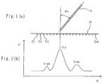
- Fig. 1(a) is a schematic side view showing a stylus pen inclined and a coordinate data input device used for the angular information input system according to the present invention;
- Fig. 1(b) is a graphical representation showing one example of distribution curve of induction voltage generated by sensing coils of the coordinate data input device shown in Fig. 1(a);
- Fig. 2(a) is a schematic side view as well as Fig. 1(a), showing a stylus pen in a virtually vertical position with respect to a coordinate data input device;
- Fig. 2(b) is a graphical representation as well as Fig. 1(b);
- Fig. 3 is a schematic perspective showing a stylus pen and a coordinate data input device used for the angular information input system according to the present invention;
- Fig. 4 is a cross sectional view taken along the line A-A shown in Fig. 3;
- Fig. 5 is a block diagram showing the circuit structure of the coordinate data input device used for the angular information input system according to the present invention;
- Fig. 6 is a circuit diagram showing the tuning circuit contained in the stylus pen used for the angular information input system according to the present invention;
- Fig. 7(a) is a schematic side view as well as Fig. 1(a), showing a stylus pen inclined and a coordinate data input device used for conventional angular information input system;
- Fig. 7(b) is a graphical representation as well as Fig. 1(b), showing one example of distribution curve of induction voltage generated by sensing coils of the coordinate data input device shown in Fig. 7(a);
- Fig. 8 is a schemtic side view showing a stylus pen containing two coils ,inclined and a coordinate data input device used for a conventional angular information input system:
- The present invention will be understood by discussion of some preferred embodiments in conjuction with the accompanying drawings. As shown in Fig. 3, an angular
information input device 10 is mainly composed of a pointing device such as astylus pen 14 and a coordinate data input panel such as adigitizer 12. Thisdigitizer 12 is typically formed in a substantially plane shape whose top is provided with adisplay panel 16 such as a liquid crystal display screen. Thisdigitizer 12 includes acontrol unit 18 and apower unit 20 which are electrically connected through any suitable means in the conventional manner. As shown in Fig. 4, thedigitizer 12 further includes an X axialdirection detecting unit 22x and a Y axial direction detecting unit 22y which are piled under thedisplay panel 16. - As shown in Fig. 5, the X axial
direction detecting unit 22x includes a plurality of sensing coils C1, C2, C3,..., C48 (referred to "Ci") which are composed of loop conductors partially overlapped and arranged in parallel with each other in the X axial direction. The longitudinal direction of these coils is oriented in the same direction; i.e., Y axial direction. Although this embodiment shows the X axialdirection detecting unit 22x including forty eight sensing coils, the present invention is not limited to this number. - One end of the sensing coil Ci is connected to a first
terminal unit 24a and the other end is connected to a secondterminal unit 24b. One terminal of the firstterminal unit 24a is selectively connected to a first selectingterminal 24c. Fig. 5 shows the first selectingterminal 24c is connected to one end of the sensing coil C1. A second selecting terminal 24d is linked with the first selectingterminal 24c so as to connect to the other end of the sensing coil Ci. These first and secondterminal units terminals 24c and 24d constitute aselective circuit 24. - The first and second selecting
terminals 24c and 24d are respectively connected to first and second selective contacts 26a and 26b of switchingunit 26. The first and second selective contacts 26a and 26b are linked with each other so as to selectively connecttransmitter terminals 26c and 26d with atransmitter 28 and receiver terminals 26e and 26f with areceiver 30. Thetransmitter 28 and thereceiver 30 are connected to anysuitable processor 32. - On the other hand, the
stylus pen 14 contains atuning circuit 34, shown in Fig. 6, which is a parallel tuning circuit composed of acoil 36, acapacitor 38 and avariable capacitor 40 which are connected to both ends of thecoil 36 in parallel. Thistuning circuit 34 has a resonant frequency capable of tuning with the frequency generated from the sensing coil Ci when electric power is applied to the sensing coil Ci. - Both ends of the
coil 36 are connected to acapacitor 44 through afirst switch 42 so that the phase of electromagnetic wave for thistuning circuit 34 is delayed at a predetermined angle, for example 90° when thefirst switch 42 is turned on whenever, for example, the pen point of thestylus pen 14 is brought into contact with the surface of thedisplay panel 16; i.e., pen down motion. Such pen down motion will occur when an operator puts thestylus pen 14 onto thedisplay panel 16 to draw characters and/or illustrations. - In addition to the
first switch 42 and thecapacitor 44, asecond switch 46 and anothercapacitor 48 are connected to the former pair in parallel so that the phase of electromagnetic wave for thistuning circuit 34 is delayed at a predetermined angle, for example 180° when thesecond switch 46 is turned on. Thesecond switch 46 is arranged at, for example the position to which any one finger of the operator can touch while the operator is handling thestylus pen 14. In order to input any information, the operator takes predetermined action such as tilting thestylus pen 14 while pressing thesecond switch 46. - One typical operation to detect the pointed coordinate by using thus constituted angular
information input device 10 will be described in detail. - Returning to Fig. 5, as the first and second selecting
terminals 24c and 24d of theselective circuit 24 select to connect the sensing coil Ci, the first and second selective contacts 26a and 26b of the switchingunit 26 also select thetransmitter terminals 26c and 26d. Thus thetransmitter 28 transmits a signal to allow the sensing coil Ci to generate an electromagnetic wave. Under this condition, when thestylus pen 14 is located in the vicinity of the sensing coil Ci, the generated electromagnetic wave energizes thecoil 36 in thestylus pen 14 to generate induction voltage in thetuning circuit 34. Then the first and second selective contacts 26a and 26b of the switchingunit 26 are switched to select the connection to the receiver terminals 26e and 26f, respectively. Thus the sensing coil Ci can not generate an electromagnetic wave, but the induction voltage remaining in thetuning circuit 34 allows thecoil 36 to generate an electromagnetic wave. This generated electromagnetic wave energizes the sensing coil Ci to generate a new induction voltage. This generated induction voltage is received by thereceiver 30, which passes it to theprocessor 32. - Successively, the first and second selecting
terminals 24c and 24d of theselective circuit 24 are switched to select the next sensing coil Ci+1. Thus the same operation as the above will be repeatedly performed and the induction voltage generated by the sensing coil Ci+1 will be input to theprocessor 32. - Fig. 2(a) and 2(b) show the relationship between the position of the
stylus pen 14 and the induction voltage generated by the sensing coil Ci. The sensing coil Ci closest to thestylus pen 14 has the maximum value (main peak Vp) of the induction voltage. Therefore, theprocessors 32 of the X and Y axialdirection detecting units 22x and 22y respectively detect the main peaks Vp as the coordinate data representing the pointed place by thestylus pen 14. - When the
first switch 42 of thestylus pen 14 is kept in ON position, the phase of the electromagnetic wave generated by thetuning circuit 34 is delayed at a predetermined angle, for example, 90° rather than that of thetransmitter 28. Thus theprocessor 32 detects the delay between the phase of the electromagnetic wave transmitted from thetransmitter 28 and the phase of the electromagnetic wave received by thereceiver 30 to distinguish ON or OFF position of thefirst switch 42. According to this distinguishing operation, the pen down motion of thestylus pen 14 can be automatically detected so that the operator can easily input a variety of information such as characters and illustrations. - Next, a typical operation to detect the inclined angle ϑ of the
stylus pen 14 by using the angularinformation input device 10 according to the present invention will be described in detail. - As the
second switch 46 is turned on, the phase of the electromagnetic wave generated by thetuning circuit 34 is delayed at a predetermined angle, for example, 180° rather than that of thetransmitter 28. Thus theprocessor 32 detects the delay between the phase of the electromagnetic wave transmitted from thetransmitter 28 and the phase of the electromagnetic wave received by thereceiver 30 to start the angular information detecting operation. - When the
stylus pen 14 is inclined with respect to the top surface of thedisplay panel 16 as shown in Fig. 1(a), the induction voltage distribution curve in the X axial direction, as shown in Fig. 1(b), has a main peak voltage Vp and two auxiliary peak voltages Vpa and Vpb at the front and rear of the main peak. In order to detect the auxiliary peak Vpa (Vpb), this embodiment employs the induction voltage generated by a specific sensing coil Ci+n (Ci-n) isolated a predetermined number "n" from the sensing coil Ci which generates the main peak voltage Vp. - It is well known by one skilled artisan that when the
stylus pen 14 is inclined in the crosswise direction with respect to the longitudinal direction of the sensing coil Ci; i.e., X axial direction as shown in Fig. 1(a), from the vertical position as shown Fig. 2(a), the auxiliary peak voltage Vpa in the inclined side is increased and the auxiliary peak voltage Vpb in the opposite side is decreased as the inclined angle ϑx is increased. On the other hand, when thestylus pen 14 is inclined in the same direction of the longitudinal direction of the sensing coil Ci; i.e., Y axial direction, from the vertical position, the auxiliary peak voltages Vpa and Vpb in the X axial direction are substantially equivalent with one another regardless of the change of the inclined angle ϑy in the Y axial direction, but the ratio between the auxiliary peak voltage Vpa or Vpb and the main peak voltage Vp is increased as the inclined angle ϑy is increased. - Therefore, the inclined angle ϑx can be provided by using these auxiliary peak voltages Vpa and Vpb in the induction voltage in the X axial direction. However, since the auxiliary peak voltage Vpa and Vpb detected by the sensing coil Ci depend on the gap between the
stylus pen 14 and the sensing coil Ci, their voltage values will be easily varied in response to a pen down motion or not, and pressure value applied to thestylus pen 14 even when thestylus pen 14 points the same coordinate position. That is, it is not desirable to calculate the inclined angles ϑx and ϑy of thestylus pen 14 by using directly the auxiliary peak voltages Vpa and Vpb. - In order to relatively normalize these auxiliary peak voltages Vpa and Vpb, the ratio between these auxiliary peak voltages and the main peak voltge Vp is calculated. For example, in the X axial direction, normalized voltages vpax and vpbx result from the ratio between the main peak voltage Vp and the auxiliary peak voltages Vpa and Vpb in the induction voltage distribution curve in the X axial direction, as shown in the following equations (3) and (4).


stylus pen 14 is inclined in only the X axial direction, these normalized values vpax, vpbx, vpay, and vpby will be respectively varied and thus the inclined angle ϑx should be calculated as the function of all normalized values vpax, vpbx, vpay, and vpby. The inclined angle ϑx in the X axial direction will be calculated in accordance with the normalized values vpax, vpbx, vpay, and vpby as shown in the following equations (7) to (12).
- The inclined angle ϑx is calculated in accordance with the relationship between the inclined angle ϑx and the above Vxt, which has been previously determined.
- When the
stylus pen 14 is inclined in the direction met at right angles with the longitudinal direction of the sensing coil Ci, particularly at 30° or more, the auxiliary peak voltage Vpb is lowered and thus errors may easily occur. In order to overcome this problem, when the inclined angle ϑx is greater than 30°, the equation (12) is preferably changed as shown in equation (13).
inclined angle 30°.
On the other hand, when thestylus pen 14 is inclined in the counter direction, the auxiliary peak voltage Vpa is lowered. Thus equation (12) should be changed as shown in equation (14).
- According to the thus resultant inclined angles ϑx and ϑy, the actual inclined angle ϑ and direction of the
stylus pen 14 can be calculated in any suitable manner as known in the prior art. Then the calculated data is input to the associated computer via theprocessor 32 so that thestylus pen 14 can be operated as well as a joystick to move a cursor. - Since the angular
information input device 10 provided as an embodiment of the present invention will enact its compensating system whenever each or both inclined angles ϑx and ϑy exceeds a predetermined value for example 30°, the inclined angles ϑx and ϑy will be accurately detected, eliminating the possible errors caused by lowering at least one of the auxiliary peak voltages. - As explained above, the angular information input system according to the present invention provides the inclined angle of the pointing device in the X and Y axial directions by calculating the function of the auxiliary peak voltages in both axial directions. This means the inclined angle in one axial direction is calculated as the fuction of both auxiliary peak voltages in both directions. Therefore, this system ensures that the inclined angle of the pointing device can be accurately detected rather than conventional inclined angle detecting systems based on only the induction voltage distribution in the inclined direction.
- Alternatively, the angular information input system according to the present invention may calculate both inclined angles of the pointing device in both X and Y axial directions by using the normalized values resulting from the function of the ratio between the main peak voltage and the auxiliary peak voltage in the X axial direction and the ratio between the main peak voltage and the auxiliary peak voltage in the Y axial direction. This system ensures the calculated inclined angle of the pointing device is free from the change of the distance between the pointing device and the coordinate data input device. In other words, the inclined angle can be correctly detected even when the auxiliary peak voltage is changed in accordance with vertical movement of the pointing device inclined at a constant angle.
- Furthermore, the angular information input system according to the present invention may detect the auxiliary peak voltage by measuring the induction voltage generated by the specific sensing coil isolated a predetermined distance away from the sensing coil generating the main peak voltage. This system ensures the auxiliary peak voltage can be easily calculated and the inclined angle of the pointing device can be detected more accurately.
- For example, when the inclined angle of the pointing device is only detected at the specific position on the coordinate data input device and the pen point contacting position is limited, the sensing coil generating the auxiliary peak voltage can be limited. Thus the auxiliary peak voltage can be easily and quickly detected by measuring only the limited coil. This system can reduce detection time and simplify the detecting constitution.
- The angular information input system according to the present invention may employ a conventional pointing device and coordinate data input device, thereby saving cost. Furthermore, this system does not need to increase the number of times for sampling the sensing coils, therefore the operator can perform input operation smoothly in the same manner as is conventionally done.
- As many apparently widely differing embodiments of this invention may be made without departing from the spirit and scope thereof, it is to be understood that the invention is not limited to the specific embodiments thereof except as defined in the appended claims.


Claims (10)
- An angular information input system comprising:
a coordinate data input device for inputting two dimensional coordiante data by detecting a first distribution of induction voltage in the X axial direction and a second distribution of induction voltage in the Y axial direction;
a pointing device for pointing the location on the coordinate data input device to generate the distributions of induction voltage in an electromagnetic coupling means of the coordinate data input device; and
a calculating means for calculating the inclined angle in the X axial direction of the pointing device in accordance with a function of auxiliary peak value of induction voltage in the X axial direction and the inclined angle in the Y axial direction of the pointing device in accordance with a function of auxiliary peak value of induction voltage in the Y axial direction. - The angular information input system as set forth in Claim 1, wherein the above described calculating means is operated to calculate the inclined angle in the X axial direction of the pointing device in accordance with a function of auxiliary peak value of induction voltage in the X axial direction and auxiliary peak value of induction voltage in the Y axial direction, and to calculate the inclined angle in the Y axial direction of the pointing device in accordance with a function of auxiliary peak value of induction voltage in the X axial direction and auxiliary peak value of induction voltage in the Y axial direction, respectively.
- The angular information input system as set forth in Claim 1, wherein the above
described calculating means is operated to calculate the inclined angle in the X axial direction of the pointing device in accordance with a function of main peak value and auxiliary peak value of induction voltage in the X axial direction and main peak value and auxiliary peak value of induction voltage in the Y axial direction, and to calculate the inclined angle in the Y axial direction of the pointing device in accordance with a function of main peak value and auxiliary peak value of induction voltage in the X axial direction and main peak value and auxiliary peak value of induction voltage in the Y axial direction, respectively. - The angular information input system as set forth in Claim 1, wherein the above described calculating means is operated to calculate the inclined angle in the X axial direction of the pointing device in accordance with a function depending on the ratio between main peak value and auxiliary peak value of induction voltage in the X axial direction and the ratio between main peak value and auxiliary peak value of induction voltage in the Y axial direction, and to calculate the inclined angle in the Y axial direction of the pointing device in accordance with a function depending on the ratio between main peak value and auxiliary peak value of induction voltage in the X axial direction and the ratio between main peak value and auxiliary peak value of induction voltage in the Y axial direction, respectively.
- The angular information input system as set forth in any one of Claims 1 to 4, wherein the above described coordinate data input device comprises a plurality of sensing coils; a detecting means for detecting induction voltage generated by the sensing coils; and a calculating means for calculating the above described main peak value and auxiliary peak from the detected induction distribution.
- The angular information input system as set forth in Claim 5, wherein the above described calculating means calculates the main peak value corresponding to the maximum voltage of the detected induction distribution and the auxiliary peak value corresponding to the induction voltage generated by a specific sensing coil isolated a predetermined distance from the maximum voltage generated coil.
- The angular information input system as set forth in any one of Claims 1 to 6, the above described pointing device is formed in a pen shape and includes a tuning circuit composed of at least one of coil.
- An information input system comprising a coordinate input device for inputting two-dimensional coordinate data by detecting voltage distributions in each of two non-parallel directions, a pointing device for causing a voltage distribution detectable by the coordinate input device to be generated and means for calculating the angle of inclination of the pointing device in each of the two directions in accordance with a function of the voltage distribution in that direction or in accordance with a function of the voltage distribution in each of the two directions.
- A system according to claim 8, wherein the calculating means is arranged to calculate the angle of inclination in each of the two directions in accordance with a function of an auxiliary peak value in that one or both of the two directions.
- A system according to claim 8, wherein the calculating means is arranged to calculate the angle of inclination of each of the two directions in accordance with a function of the main and an auxiliary peak voltage in that or in each of the two directions.
Applications Claiming Priority (3)
| Application Number | Priority Date | Filing Date | Title |
|---|---|---|---|
| JP11179194AJP3510318B2 (en) | 1994-04-28 | 1994-04-28 | Angle information input device |
| JP111791/94 | 1994-04-28 | ||
| JP11179194 | 1994-04-28 |
Publications (3)
| Publication Number | Publication Date |
|---|---|
| EP0680009A2true EP0680009A2 (en) | 1995-11-02 |
| EP0680009A3 EP0680009A3 (en) | 1996-06-26 |
| EP0680009B1 EP0680009B1 (en) | 2000-05-24 |
Family
ID=14570251
Family Applications (1)
| Application Number | Title | Priority Date | Filing Date |
|---|---|---|---|
| EP95302089AExpired - LifetimeEP0680009B1 (en) | 1994-04-28 | 1995-03-29 | Angular information input system |
Country Status (4)
| Country | Link |
|---|---|
| US (1) | US5751229A (en) |
| EP (1) | EP0680009B1 (en) |
| JP (1) | JP3510318B2 (en) |
| DE (1) | DE69517086T2 (en) |
Cited By (20)
| Publication number | Priority date | Publication date | Assignee | Title |
|---|---|---|---|---|
| WO2000033244A3 (en)* | 1998-11-27 | 2000-11-09 | Synaptics Uk Ltd | Position sensor |
| US6249234B1 (en) | 1994-05-14 | 2001-06-19 | Absolute Sensors Limited | Position detector |
| US6304014B1 (en) | 1997-10-02 | 2001-10-16 | Synaptics (Uk) Limited | Motor control system |
| US6522128B1 (en) | 1997-10-15 | 2003-02-18 | Synaptics (Uk) Limited | Position sensor having compact arrangement of coils |
| US6534970B1 (en) | 1998-05-22 | 2003-03-18 | Synaptics (Uk) Limited | Rotary position sensor and transducer for use therein |
| US6705511B1 (en) | 1997-05-28 | 2004-03-16 | Synaptics (Uk) Limited | Transducer and method of manufacture |
| US6788221B1 (en) | 1996-06-28 | 2004-09-07 | Synaptics (Uk) Limited | Signal processing apparatus and method |
| US7019672B2 (en) | 1998-12-24 | 2006-03-28 | Synaptics (Uk) Limited | Position sensor |
| US7030782B2 (en) | 1994-05-14 | 2006-04-18 | Synaptics (Uk) Limited | Position detector |
| US7133793B2 (en) | 2003-07-24 | 2006-11-07 | Synaptics (Uk) Limited | Magnetic calibration array |
| US7406393B2 (en) | 2002-03-05 | 2008-07-29 | Synaptics (Uk) Limited | Position sensor |
| EP1437643A4 (en)* | 2001-09-25 | 2009-01-07 | Taiguen Tech Shenzhen Co Ltd | Panel display screen with touch control function |
| US7511705B2 (en) | 2001-05-21 | 2009-03-31 | Synaptics (Uk) Limited | Position sensor |
| US7812268B2 (en) | 2003-08-26 | 2010-10-12 | Synaptics (Uk) Limited | Digitizer system |
| US7907130B2 (en) | 2002-06-05 | 2011-03-15 | Synaptics (Uk) Limited | Signal transfer method and apparatus |
| US8570028B2 (en) | 2007-05-10 | 2013-10-29 | Cambridge Integrated Circuits Limited | Transducer for a position sensor |
| US9410791B2 (en) | 2010-12-24 | 2016-08-09 | Cambridge Integrated Circuits Limited | Position sensing transducer |
| EP2530567A3 (en)* | 2011-06-03 | 2016-09-07 | Samsung Electronics Co., Ltd. | Electromagnetic resonance sensing apparatus using small number of channels |
| US9470505B2 (en) | 2012-06-13 | 2016-10-18 | Cambridge Integrated Circuits Limited | Position sensing transducer |
| US9519386B2 (en) | 2013-08-06 | 2016-12-13 | Samsung Electronics Co., Ltd. | Input device and electronic device including the same |
Families Citing this family (42)
| Publication number | Priority date | Publication date | Assignee | Title |
|---|---|---|---|---|
| JPH10326146A (en)* | 1997-05-23 | 1998-12-08 | Wacom Co Ltd | Tool for coordinate input |
| US6337698B1 (en)* | 1998-11-20 | 2002-01-08 | Microsoft Corporation | Pen-based interface for a notepad computer |
| US6738044B2 (en)* | 2000-08-07 | 2004-05-18 | The Regents Of The University Of California | Wireless, relative-motion computer input device |
| JP2002073268A (en) | 2000-09-04 | 2002-03-12 | Brother Ind Ltd | Coordinate reading device |
| US6806865B2 (en)* | 2001-02-05 | 2004-10-19 | Palm, Inc. | Integrated joypad for handheld computer |
| JP2003280785A (en)* | 2002-03-26 | 2003-10-02 | Sony Corp | Image display processor, image display processing method and computer program |
| TW544974B (en)* | 2002-07-25 | 2003-08-01 | Aiptek Int Inc | An electromagnetic inductive system with multi-antenna loop layout and battery less pointer device and its method for locating the coordinate |
| US6970285B2 (en)* | 2004-03-02 | 2005-11-29 | Hewlett-Packard Development Company, L.P. | Phase change electrophoretic imaging for rewritable applications |
| US8228299B1 (en) | 2005-01-27 | 2012-07-24 | Singleton Technology, Llc | Transaction automation and archival system using electronic contract and disclosure units |
| US8194045B1 (en) | 2005-01-27 | 2012-06-05 | Singleton Technology, Llc | Transaction automation and archival system using electronic contract disclosure units |
| CN100347648C (en)* | 2005-02-02 | 2007-11-07 | 陈其良 | Azimuth type computer inputting device |
| US9201556B2 (en) | 2006-11-08 | 2015-12-01 | 3M Innovative Properties Company | Touch location sensing system and method employing sensor data fitting to a predefined curve |
| US8207944B2 (en)* | 2006-12-19 | 2012-06-26 | 3M Innovative Properties Company | Capacitance measuring circuit and method |
| US8134542B2 (en)* | 2006-12-20 | 2012-03-13 | 3M Innovative Properties Company | Untethered stylus employing separate communication and power channels |
| US8040329B2 (en) | 2006-12-20 | 2011-10-18 | 3M Innovative Properties Company | Frequency control circuit for tuning a resonant circuit of an untethered device |
| US7956851B2 (en)* | 2006-12-20 | 2011-06-07 | 3M Innovative Properties Company | Self-tuning drive source employing input impedance phase detection |
| US8243049B2 (en) | 2006-12-20 | 2012-08-14 | 3M Innovative Properties Company | Untethered stylus employing low current power converter |
| US8040330B2 (en) | 2006-12-28 | 2011-10-18 | 3M Innovative Properties Company | Untethered stylus empolying multiple reference frequency communication |
| US8089474B2 (en) | 2006-12-28 | 2012-01-03 | 3M Innovative Properties Company | Location sensing system and method employing adaptive drive signal adjustment |
| US7787259B2 (en)* | 2006-12-28 | 2010-08-31 | 3M Innovative Properties Company | Magnetic shield for use in a location sensing system |
| US8629358B2 (en) | 2007-09-26 | 2014-01-14 | N-Trig Ltd. | Method for identifying changes in signal frequencies emitted by a stylus interacting with a digitizer sensor |
| TWI419018B (en)* | 2010-02-04 | 2013-12-11 | Waltop Int Corp | Method for determining incline angle of electromagnetic pointer |
| CN102147457B (en)* | 2010-02-10 | 2013-01-02 | 太瀚科技股份有限公司 | Method for detecting tilt angle of electromagnetic input pen |
| JP5094905B2 (en)* | 2010-04-13 | 2012-12-12 | 太瀚科技股▲ふん▼有限公司 | Method for detecting tilt angle of electromagnetic pointer |
| US8781789B2 (en) | 2010-05-11 | 2014-07-15 | Waltop International Corporation | Method for determining incline angle of electromagnetic pointer |
| TW201140384A (en)* | 2010-05-12 | 2011-11-16 | Prime View Int Co Ltd | Display device having stylus pen with joystick functions |
| TWI414979B (en)* | 2010-08-16 | 2013-11-11 | Waltop Int Corp | Handwriting input device and angle correction method thereof |
| CN102375646B (en)* | 2010-08-18 | 2017-01-18 | 株式会社和冠 | Handwriting input device and its angle correction method |
| JP2012133704A (en)* | 2010-12-24 | 2012-07-12 | Wacom Co Ltd | Input device |
| JP5656652B2 (en)* | 2011-01-07 | 2015-01-21 | キヤノン株式会社 | Touch panel device and touch panel detection position correction method |
| US20130234984A1 (en)* | 2012-03-06 | 2013-09-12 | Industry-University Cooperation Foundation Hanyang University | System for linking and controlling terminals and user terminal used in the same |
| KR20130107473A (en)* | 2012-03-22 | 2013-10-02 | 삼성전자주식회사 | Capactive type touch pen |
| KR102066017B1 (en)* | 2012-05-11 | 2020-01-14 | 삼성전자주식회사 | Coordinate indicating apparatus and coordinate measuring apparaturs which measures input position of coordinate indicating apparatus |
| KR102010237B1 (en)* | 2012-07-03 | 2019-08-13 | 삼성전자주식회사 | Coordinate calibration method of digitizer, apparatus thereof, and electronic pen thereof |
| US20140168175A1 (en)* | 2012-12-13 | 2014-06-19 | Research In Motion Limited | Magnetically coupling stylus and host electronic device |
| TWI501118B (en)* | 2013-06-18 | 2015-09-21 | Wacom Co Ltd | Method for determining incline angle of electromagnetic pointer |
| KR102106779B1 (en)* | 2013-06-28 | 2020-05-06 | 삼성전자주식회사 | Method for processing pen input and apparatus for the same |
| KR101800295B1 (en) | 2013-09-04 | 2017-12-20 | 엘지디스플레이 주식회사 | Position detection method, position detection apparatus, antenna apparatus, and display apparatus |
| TWI601053B (en) | 2014-02-12 | 2017-10-01 | 元太科技工業股份有限公司 | Correction method of touch point and electromagnetic-type touch panel using the same |
| CN113358012B (en)* | 2020-03-06 | 2022-12-02 | 深圳普赢创新科技股份有限公司 | Electromagnetic induction type coordinate positioning device |
| JPWO2022176767A1 (en)* | 2021-02-17 | 2022-08-25 | ||
| JP7664720B2 (en) | 2021-03-15 | 2025-04-18 | 株式会社ワコム | Position detection sensor and position detection device |
Family Cites Families (7)
| Publication number | Priority date | Publication date | Assignee | Title |
|---|---|---|---|---|
| JPS5920156B2 (en)* | 1980-07-10 | 1984-05-11 | セイコーインスツルメンツ株式会社 | coordinate reading device |
| JPH02249019A (en)* | 1989-03-22 | 1990-10-04 | Seiko Instr Inc | Coordinate input device |
| JPH0367320A (en)* | 1989-05-01 | 1991-03-22 | Wacom Co Ltd | Angle information input device |
| US4939318A (en)* | 1989-11-06 | 1990-07-03 | Calcomp Inc. | Digitizer pen tilt correction employing wires near the data point |
| JPH03175521A (en)* | 1989-12-04 | 1991-07-30 | Seiko Instr Inc | Coordinate reader |
| US5198623A (en)* | 1991-11-27 | 1993-03-30 | Calcomp, Inc. | Method for use in a digitizer for determining pen tilt |
| JP2771788B2 (en)* | 1995-05-18 | 1998-07-02 | 株式会社ワコム | Coordinate detecting device and angle information detecting method |
- 1994
- 1994-04-28JPJP11179194Apatent/JP3510318B2/ennot_activeExpired - Lifetime
- 1995
- 1995-03-29EPEP95302089Apatent/EP0680009B1/ennot_activeExpired - Lifetime
- 1995-03-29DEDE69517086Tpatent/DE69517086T2/ennot_activeExpired - Lifetime
- 1995-04-13USUS08/421,270patent/US5751229A/ennot_activeExpired - Lifetime
Cited By (26)
| Publication number | Priority date | Publication date | Assignee | Title |
|---|---|---|---|---|
| US6249234B1 (en) | 1994-05-14 | 2001-06-19 | Absolute Sensors Limited | Position detector |
| US6489899B1 (en) | 1994-05-14 | 2002-12-03 | Synaptics (Uk) Limited | Position detector |
| US7030782B2 (en) | 1994-05-14 | 2006-04-18 | Synaptics (Uk) Limited | Position detector |
| US6888538B2 (en) | 1994-05-14 | 2005-05-03 | Synaptics (Uk) Limited | Position sensor |
| US6980134B2 (en) | 1996-06-28 | 2005-12-27 | Synaptics (Uk) Limited | Signal processing apparatus and method |
| US6788221B1 (en) | 1996-06-28 | 2004-09-07 | Synaptics (Uk) Limited | Signal processing apparatus and method |
| US6705511B1 (en) | 1997-05-28 | 2004-03-16 | Synaptics (Uk) Limited | Transducer and method of manufacture |
| US6304014B1 (en) | 1997-10-02 | 2001-10-16 | Synaptics (Uk) Limited | Motor control system |
| US6522128B1 (en) | 1997-10-15 | 2003-02-18 | Synaptics (Uk) Limited | Position sensor having compact arrangement of coils |
| US6534970B1 (en) | 1998-05-22 | 2003-03-18 | Synaptics (Uk) Limited | Rotary position sensor and transducer for use therein |
| US6667740B2 (en) | 1998-11-27 | 2003-12-23 | Synaptics (Uk) Limited | Position sensor |
| WO2000033244A3 (en)* | 1998-11-27 | 2000-11-09 | Synaptics Uk Ltd | Position sensor |
| US7019672B2 (en) | 1998-12-24 | 2006-03-28 | Synaptics (Uk) Limited | Position sensor |
| US7511705B2 (en) | 2001-05-21 | 2009-03-31 | Synaptics (Uk) Limited | Position sensor |
| US8243033B2 (en) | 2001-05-21 | 2012-08-14 | Synaptics (Uk) Limited | Position sensor |
| EP1437643A4 (en)* | 2001-09-25 | 2009-01-07 | Taiguen Tech Shenzhen Co Ltd | Panel display screen with touch control function |
| US7406393B2 (en) | 2002-03-05 | 2008-07-29 | Synaptics (Uk) Limited | Position sensor |
| US7907130B2 (en) | 2002-06-05 | 2011-03-15 | Synaptics (Uk) Limited | Signal transfer method and apparatus |
| US7133793B2 (en) | 2003-07-24 | 2006-11-07 | Synaptics (Uk) Limited | Magnetic calibration array |
| US7812268B2 (en) | 2003-08-26 | 2010-10-12 | Synaptics (Uk) Limited | Digitizer system |
| US8022317B2 (en) | 2003-08-26 | 2011-09-20 | Synaptics (Uk) Limited | Digitizer system |
| US8570028B2 (en) | 2007-05-10 | 2013-10-29 | Cambridge Integrated Circuits Limited | Transducer for a position sensor |
| US9410791B2 (en) | 2010-12-24 | 2016-08-09 | Cambridge Integrated Circuits Limited | Position sensing transducer |
| EP2530567A3 (en)* | 2011-06-03 | 2016-09-07 | Samsung Electronics Co., Ltd. | Electromagnetic resonance sensing apparatus using small number of channels |
| US9470505B2 (en) | 2012-06-13 | 2016-10-18 | Cambridge Integrated Circuits Limited | Position sensing transducer |
| US9519386B2 (en) | 2013-08-06 | 2016-12-13 | Samsung Electronics Co., Ltd. | Input device and electronic device including the same |
Also Published As
| Publication number | Publication date |
|---|---|
| US5751229A (en) | 1998-05-12 |
| DE69517086D1 (en) | 2000-06-29 |
| DE69517086T2 (en) | 2009-09-17 |
| EP0680009A3 (en) | 1996-06-26 |
| EP0680009B1 (en) | 2000-05-24 |
| JPH07295729A (en) | 1995-11-10 |
| JP3510318B2 (en) | 2004-03-29 |
Similar Documents
| Publication | Publication Date | Title |
|---|---|---|
| EP0680009B1 (en) | Angular information input system | |
| KR100222804B1 (en) | Coordinate detection apparatus and method, and computer control apparatus | |
| KR100537931B1 (en) | Digitizer system with cursor shape changing as a function of pointer location on menu strip | |
| EP0816992B1 (en) | Coordinate input apparatus | |
| KR100480823B1 (en) | touch panel for display device | |
| US6998856B2 (en) | Apparatus for sensing the position of a pointing object | |
| JP2599019B2 (en) | Pen input device | |
| US6034672A (en) | Device for multimode management of a cursor on the screen of a display device | |
| US5693914A (en) | Digitizer and method of detecting positions | |
| KR100459230B1 (en) | touch panel for display device | |
| US10579198B2 (en) | Indicator detecting device and signal processing method thereof | |
| US6532003B2 (en) | Data processing apparatus having control element for detecting false touch | |
| US11221688B2 (en) | Input apparatus with relation between pen and finger touches | |
| JPH0695796A (en) | Pen input device | |
| GB2139762A (en) | An input device and a method of inputting data to a computer system | |
| JP2010244302A (en) | Input device and input processing method | |
| CN1402116A (en) | Device with touch screen using connected external apparatus for displaying information, and method thereof | |
| JPH08179871A (en) | Transparent digitizer for touch panel | |
| JP3402858B2 (en) | Coordinate detection method and device, and computer control device | |
| JP3161794B2 (en) | Pen input device and pen input method | |
| JPH0367320A (en) | Angle information input device | |
| JPH08328725A (en) | Coordinate input device | |
| JP3209378B2 (en) | Information processing apparatus and control method thereof | |
| KR20040034915A (en) | Apparatus for implementing dynamic keyboard in pen computing system | |
| JPS5819939A (en) | input device |
Legal Events
| Date | Code | Title | Description |
|---|---|---|---|
| PUAI | Public reference made under article 153(3) epc to a published international application that has entered the european phase | Free format text:ORIGINAL CODE: 0009012 | |
| AK | Designated contracting states | Kind code of ref document:A2 Designated state(s):DE ES FR GB IT PT | |
| PUAL | Search report despatched | Free format text:ORIGINAL CODE: 0009013 | |
| 17P | Request for examination filed | Effective date:19960328 | |
| AK | Designated contracting states | Kind code of ref document:A3 Designated state(s):DE ES FR GB IT PT | |
| 17Q | First examination report despatched | Effective date:19990222 | |
| GRAG | Despatch of communication of intention to grant | Free format text:ORIGINAL CODE: EPIDOS AGRA | |
| GRAG | Despatch of communication of intention to grant | Free format text:ORIGINAL CODE: EPIDOS AGRA | |
| GRAH | Despatch of communication of intention to grant a patent | Free format text:ORIGINAL CODE: EPIDOS IGRA | |
| GRAH | Despatch of communication of intention to grant a patent | Free format text:ORIGINAL CODE: EPIDOS IGRA | |
| GRAA | (expected) grant | Free format text:ORIGINAL CODE: 0009210 | |
| AK | Designated contracting states | Kind code of ref document:B1 Designated state(s):DE ES FR GB IT PT | |
| PG25 | Lapsed in a contracting state [announced via postgrant information from national office to epo] | Ref country code:IT Free format text:LAPSE BECAUSE OF FAILURE TO SUBMIT A TRANSLATION OF THE DESCRIPTION OR TO PAY THE FEE WITHIN THE PRE;WARNING: LAPSES OF ITALIAN PATENTS WITH EFFECTIVE DATE BEFORE 2007 MAY HAVE OCCURRED AT ANY TIME BEFORE 2007. THE CORRECT EFFECTIVE DATE MAY BE DIFFERENT FROM THE ONE RECORDED.SCRIBED TIME-LIMIT Effective date:20000524 Ref country code:FR Free format text:LAPSE BECAUSE OF FAILURE TO SUBMIT A TRANSLATION OF THE DESCRIPTION OR TO PAY THE FEE WITHIN THE PRESCRIBED TIME-LIMIT Effective date:20000524 Ref country code:ES Free format text:THE PATENT HAS BEEN ANNULLED BY A DECISION OF A NATIONAL AUTHORITY Effective date:20000524 | |
| REF | Corresponds to: | Ref document number:69517086 Country of ref document:DE Date of ref document:20000629 | |
| PG25 | Lapsed in a contracting state [announced via postgrant information from national office to epo] | Ref country code:PT Free format text:LAPSE BECAUSE OF FAILURE TO SUBMIT A TRANSLATION OF THE DESCRIPTION OR TO PAY THE FEE WITHIN THE PRESCRIBED TIME-LIMIT Effective date:20000824 | |
| EN | Fr: translation not filed | ||
| PLBE | No opposition filed within time limit | Free format text:ORIGINAL CODE: 0009261 | |
| STAA | Information on the status of an ep patent application or granted ep patent | Free format text:STATUS: NO OPPOSITION FILED WITHIN TIME LIMIT | |
| 26N | No opposition filed | ||
| REG | Reference to a national code | Ref country code:GB Ref legal event code:IF02 | |
| PGFP | Annual fee paid to national office [announced via postgrant information from national office to epo] | Ref country code:DE Payment date:20140328 Year of fee payment:20 | |
| PGFP | Annual fee paid to national office [announced via postgrant information from national office to epo] | Ref country code:GB Payment date:20140319 Year of fee payment:20 | |
| REG | Reference to a national code | Ref country code:DE Ref legal event code:R071 Ref document number:69517086 Country of ref document:DE | |
| REG | Reference to a national code | Ref country code:DE Ref legal event code:R071 Ref document number:69517086 Country of ref document:DE | |
| REG | Reference to a national code | Ref country code:GB Ref legal event code:PE20 Expiry date:20150328 | |
| PG25 | Lapsed in a contracting state [announced via postgrant information from national office to epo] | Ref country code:GB Free format text:LAPSE BECAUSE OF EXPIRATION OF PROTECTION Effective date:20150328 |