EP0679799B1 - Exhaust particulate filter for diesel engine - Google Patents
Exhaust particulate filter for diesel engineDownload PDFInfo
- Publication number
- EP0679799B1 EP0679799B1EP95302736AEP95302736AEP0679799B1EP 0679799 B1EP0679799 B1EP 0679799B1EP 95302736 AEP95302736 AEP 95302736AEP 95302736 AEP95302736 AEP 95302736AEP 0679799 B1EP0679799 B1EP 0679799B1
- Authority
- EP
- European Patent Office
- Prior art keywords
- exhaust
- particulate filter
- filter
- exhaust particulate
- tubular
- Prior art date
- Legal status (The legal status is an assumption and is not a legal conclusion. Google has not performed a legal analysis and makes no representation as to the accuracy of the status listed.)
- Expired - Lifetime
Links
Images


Classifications
- B—PERFORMING OPERATIONS; TRANSPORTING
- B01—PHYSICAL OR CHEMICAL PROCESSES OR APPARATUS IN GENERAL
- B01D—SEPARATION
- B01D46/00—Filters or filtering processes specially modified for separating dispersed particles from gases or vapours
- B01D46/24—Particle separators, e.g. dust precipitators, using rigid hollow filter bodies
- B01D46/2403—Particle separators, e.g. dust precipitators, using rigid hollow filter bodies characterised by the physical shape or structure of the filtering element
- B01D46/2418—Honeycomb filters
- B—PERFORMING OPERATIONS; TRANSPORTING
- B01—PHYSICAL OR CHEMICAL PROCESSES OR APPARATUS IN GENERAL
- B01D—SEPARATION
- B01D39/00—Filtering material for liquid or gaseous fluids
- B01D39/14—Other self-supporting filtering material ; Other filtering material
- B01D39/20—Other self-supporting filtering material ; Other filtering material of inorganic material, e.g. asbestos paper, metallic filtering material of non-woven wires
- B01D39/2068—Other inorganic materials, e.g. ceramics
- B01D39/2082—Other inorganic materials, e.g. ceramics the material being filamentary or fibrous
- B—PERFORMING OPERATIONS; TRANSPORTING
- B01—PHYSICAL OR CHEMICAL PROCESSES OR APPARATUS IN GENERAL
- B01D—SEPARATION
- B01D46/00—Filters or filtering processes specially modified for separating dispersed particles from gases or vapours
- B01D46/0084—Filters or filtering processes specially modified for separating dispersed particles from gases or vapours provided with safety means
- B01D46/0087—Bypass or safety valves
- B—PERFORMING OPERATIONS; TRANSPORTING
- B01—PHYSICAL OR CHEMICAL PROCESSES OR APPARATUS IN GENERAL
- B01D—SEPARATION
- B01D46/00—Filters or filtering processes specially modified for separating dispersed particles from gases or vapours
- B01D46/66—Regeneration of the filtering material or filter elements inside the filter
- B01D46/80—Chemical processes for the removal of the retained particles, e.g. by burning
- B01D46/84—Chemical processes for the removal of the retained particles, e.g. by burning by heating only
- F—MECHANICAL ENGINEERING; LIGHTING; HEATING; WEAPONS; BLASTING
- F01—MACHINES OR ENGINES IN GENERAL; ENGINE PLANTS IN GENERAL; STEAM ENGINES
- F01N—GAS-FLOW SILENCERS OR EXHAUST APPARATUS FOR MACHINES OR ENGINES IN GENERAL; GAS-FLOW SILENCERS OR EXHAUST APPARATUS FOR INTERNAL-COMBUSTION ENGINES
- F01N3/00—Exhaust or silencing apparatus having means for purifying, rendering innocuous, or otherwise treating exhaust
- F01N3/02—Exhaust or silencing apparatus having means for purifying, rendering innocuous, or otherwise treating exhaust for cooling, or for removing solid constituents of, exhaust
- F01N3/021—Exhaust or silencing apparatus having means for purifying, rendering innocuous, or otherwise treating exhaust for cooling, or for removing solid constituents of, exhaust by means of filters
- F01N3/022—Exhaust or silencing apparatus having means for purifying, rendering innocuous, or otherwise treating exhaust for cooling, or for removing solid constituents of, exhaust by means of filters characterised by specially adapted filtering structure, e.g. honeycomb, mesh or fibrous
- F01N3/0226—Exhaust or silencing apparatus having means for purifying, rendering innocuous, or otherwise treating exhaust for cooling, or for removing solid constituents of, exhaust by means of filters characterised by specially adapted filtering structure, e.g. honeycomb, mesh or fibrous the structure being fibrous
- F—MECHANICAL ENGINEERING; LIGHTING; HEATING; WEAPONS; BLASTING
- F01—MACHINES OR ENGINES IN GENERAL; ENGINE PLANTS IN GENERAL; STEAM ENGINES
- F01N—GAS-FLOW SILENCERS OR EXHAUST APPARATUS FOR MACHINES OR ENGINES IN GENERAL; GAS-FLOW SILENCERS OR EXHAUST APPARATUS FOR INTERNAL-COMBUSTION ENGINES
- F01N3/00—Exhaust or silencing apparatus having means for purifying, rendering innocuous, or otherwise treating exhaust
- F01N3/02—Exhaust or silencing apparatus having means for purifying, rendering innocuous, or otherwise treating exhaust for cooling, or for removing solid constituents of, exhaust
- F01N3/021—Exhaust or silencing apparatus having means for purifying, rendering innocuous, or otherwise treating exhaust for cooling, or for removing solid constituents of, exhaust by means of filters
- F01N3/023—Exhaust or silencing apparatus having means for purifying, rendering innocuous, or otherwise treating exhaust for cooling, or for removing solid constituents of, exhaust by means of filters using means for regenerating the filters, e.g. by burning trapped particles
- F01N3/027—Exhaust or silencing apparatus having means for purifying, rendering innocuous, or otherwise treating exhaust for cooling, or for removing solid constituents of, exhaust by means of filters using means for regenerating the filters, e.g. by burning trapped particles using electric or magnetic heating means
- B—PERFORMING OPERATIONS; TRANSPORTING
- B01—PHYSICAL OR CHEMICAL PROCESSES OR APPARATUS IN GENERAL
- B01D—SEPARATION
- B01D2239/00—Aspects relating to filtering material for liquid or gaseous fluids
- B01D2239/04—Additives and treatments of the filtering material
- B01D2239/0471—Surface coating material
- B01D2239/0492—Surface coating material on fibres
- B—PERFORMING OPERATIONS; TRANSPORTING
- B01—PHYSICAL OR CHEMICAL PROCESSES OR APPARATUS IN GENERAL
- B01D—SEPARATION
- B01D2239/00—Aspects relating to filtering material for liquid or gaseous fluids
- B01D2239/06—Filter cloth, e.g. knitted, woven non-woven; self-supported material
- B01D2239/065—More than one layer present in the filtering material
- B01D2239/0659—The layers being joined by needling
- B—PERFORMING OPERATIONS; TRANSPORTING
- B01—PHYSICAL OR CHEMICAL PROCESSES OR APPARATUS IN GENERAL
- B01D—SEPARATION
- B01D2239/00—Aspects relating to filtering material for liquid or gaseous fluids
- B01D2239/10—Filtering material manufacturing
- B—PERFORMING OPERATIONS; TRANSPORTING
- B01—PHYSICAL OR CHEMICAL PROCESSES OR APPARATUS IN GENERAL
- B01D—SEPARATION
- B01D2239/00—Aspects relating to filtering material for liquid or gaseous fluids
- B01D2239/12—Special parameters characterising the filtering material
- B01D2239/1208—Porosity
- B—PERFORMING OPERATIONS; TRANSPORTING
- B01—PHYSICAL OR CHEMICAL PROCESSES OR APPARATUS IN GENERAL
- B01D—SEPARATION
- B01D2239/00—Aspects relating to filtering material for liquid or gaseous fluids
- B01D2239/12—Special parameters characterising the filtering material
- B01D2239/1225—Fibre length
- B—PERFORMING OPERATIONS; TRANSPORTING
- B01—PHYSICAL OR CHEMICAL PROCESSES OR APPARATUS IN GENERAL
- B01D—SEPARATION
- B01D2239/00—Aspects relating to filtering material for liquid or gaseous fluids
- B01D2239/12—Special parameters characterising the filtering material
- B01D2239/1233—Fibre diameter
- B—PERFORMING OPERATIONS; TRANSPORTING
- B01—PHYSICAL OR CHEMICAL PROCESSES OR APPARATUS IN GENERAL
- B01D—SEPARATION
- B01D2279/00—Filters adapted for separating dispersed particles from gases or vapours specially modified for specific uses
- B01D2279/30—Filters adapted for separating dispersed particles from gases or vapours specially modified for specific uses for treatment of exhaust gases from IC Engines
- F—MECHANICAL ENGINEERING; LIGHTING; HEATING; WEAPONS; BLASTING
- F02—COMBUSTION ENGINES; HOT-GAS OR COMBUSTION-PRODUCT ENGINE PLANTS
- F02B—INTERNAL-COMBUSTION PISTON ENGINES; COMBUSTION ENGINES IN GENERAL
- F02B3/00—Engines characterised by air compression and subsequent fuel addition
- F02B3/06—Engines characterised by air compression and subsequent fuel addition with compression ignition
- Y—GENERAL TAGGING OF NEW TECHNOLOGICAL DEVELOPMENTS; GENERAL TAGGING OF CROSS-SECTIONAL TECHNOLOGIES SPANNING OVER SEVERAL SECTIONS OF THE IPC; TECHNICAL SUBJECTS COVERED BY FORMER USPC CROSS-REFERENCE ART COLLECTIONS [XRACs] AND DIGESTS
- Y10—TECHNICAL SUBJECTS COVERED BY FORMER USPC
- Y10S—TECHNICAL SUBJECTS COVERED BY FORMER USPC CROSS-REFERENCE ART COLLECTIONS [XRACs] AND DIGESTS
- Y10S55/00—Gas separation
- Y10S55/10—Residue burned
- Y—GENERAL TAGGING OF NEW TECHNOLOGICAL DEVELOPMENTS; GENERAL TAGGING OF CROSS-SECTIONAL TECHNOLOGIES SPANNING OVER SEVERAL SECTIONS OF THE IPC; TECHNICAL SUBJECTS COVERED BY FORMER USPC CROSS-REFERENCE ART COLLECTIONS [XRACs] AND DIGESTS
- Y10—TECHNICAL SUBJECTS COVERED BY FORMER USPC
- Y10S—TECHNICAL SUBJECTS COVERED BY FORMER USPC CROSS-REFERENCE ART COLLECTIONS [XRACs] AND DIGESTS
- Y10S55/00—Gas separation
- Y10S55/30—Exhaust treatment
Definitions
- the present inventionrelates to an exhaust particulate (finely-divided) filter for a diesel engine, and particularly to an exhaust particulate filter using heat resistant inorganic lengthy fibers.
- Exhaust particulate filters for collecting exhaust finely-divided particular such as graphite called "particulate" in exhausts from the diesel engine so far knowninclude a filter using a porous honeycomb body formed of cordilite ceramics and silicon carbide, a filter using a foam-like pore body of ceramics and a filter using a woven fabric formed of inorganic fibers.
- US Patent number 3,871,850discloses a filter element adapted to remove fine particulates from the exhaust gas of internal combustion engines comprising a non-woven fiber not bonded to a wire mesh.
- Reproducing methods of the exhaust particulate filter formed of ceramicsinclude a method for igniting and burning the exhaust particulate collected on the surface by a flame of a burner, a method making used of combustion propagation, and a method for igniting and burning the particulates by electric heat.
- a further methodcomprises causing air flow against the exhaust flow in the exhaust particulate filter, removing the exhaust finely-divided particulates collected on the surface of the exhaust particulate filter and thereafter burning the particulates.
- the above-mentioned exhaust particulate filter formed of ceramicsis necessary to have a relatively wide surface area corresponding to the exhaust flow rate of the diesel engine since pores formed in the surface on which the exhaust particulates are collected are smaller than the exhaust particulates.
- the pores of the exhaust particulate filterbecome smaller and smaller so that the exhaust particulates are accumulated on the surface of the exhaust particulate filter, and the pressure loss caused by the fluid resistance of the exhaust particulate filter abruptly increases.
- a combustion temperatureis 1400° C, resulting in a breakage or melting of the exhaust particulate filter. Even if the combustion temperature is below 1400° C, the combustion propagation is not uniformly performed, and the exhaust particulate filter is sometimes cracked due to the thermal stress.
- the exhaust particulate filter formed of inorganic fibersis necessary to have a wide surface area since the filter collects the exhaust particulates on the surface thereof.
- an object of the present inventionis to provide an exhaust particulate filter for a diesel engine which is high in the collecting efficiency of exhaust particulates and small in the pressure loss, by using a felt-like body having pores of an optimum size between heat resistant inorganic lengthy fibers.
- the present invetionprovides an exhaust particulate filter for a diesel engine, comprising a tubular exhaust body having an exhaust inlet and an exhaust outlet, a first tubular filter body mounted within the tubular exhaust body, the first tubular filter body comprising a felt-like body having heat resistant inorganic lengthy fibers cut into a predetermined length, irregularly orientated in a horizontal direction and laminated, said inorganic lengthy fibers being vertically entangled by applying needles, characterised in that the exhaust particulate filter further comprises wire nets formed of heat resistant metal on both inner and outer surfaces of the felt-like body, the wire nets being arrested with said filter-like body by heat resistant yarn, a second tubular filter body coaxially disposed within the first tubular filter body, a bulk head tube coaxially disposed between the first and second tubular filter bodies, a sensor disposed proximate to the exhaust inlet to detect the exhaust flow rate and pressure in the exhaust inlet, a valve for controlling the proportion of the exhaust gas which in use
- the felt-like body having pores having an optimum inner diameter between the heat resistant inorganic lengthy fibersefficiently collects the exhaust particulates not only on the surface thereof but also on the portions internally of the surface.
- the wire netsWith respect to the heat resistant wire nets put upon the both surfaces of the felt like body, the wire nets are energized to thereby burn the collected exhaust particulates.
- Fig. 1is a side view showing a schematic configuration of an exhaust purifying apparatus of a diesel engine using an exhaust particulate filter according to the present invention
- Fig. 2is a sectional view in side of the exhaust purifying apparatus.
- the exhaust purifying apparatuscomprises a thermal insulating material 6 attached to an inner peripheral surface of a tubular vessel 5, a tubular exhaust particulate filter 16 formed of porous metal (metal foam) disposed on the diametrically central part, a bulkhead tube 23 disposed on the outer peripheral side of the exhaust particulate filter 16, and a double-tube type exhaust particulate filter 22 formed of inorganic lengthy fibers disposed in an annular space between the vessel 5 and the bulkhead tube 23.
- a thermal insulating material 6attached to an inner peripheral surface of a tubular vessel 5
- a tubular exhaust particulate filter 16formed of porous metal (metal foam) disposed on the diametrically central part
- a bulkhead tube 23disposed on the outer peripheral side of the exhaust particulate
- the exhaust particulate filter 22can be constructed such that a plurality of elongated cup-like elements are disposed at peripheral equal intervals in the annular space between the vessel 5 and the bulkhead tube 23.
- the exhaust particulate filter 16 and the bulkhead tube 23are supported on an annular plate 21 disposed at an inlet end (a left end) of the vessel 5.
- the double-tube type exhaust particulate filter 22, right end wall 25 of which is closedis also supported in its left end by the annular plate 21, which is provided with a number of openings at peripheral equal intervals in communication with a left end inlet 24 of the exhaust particulate filter 22.
- a tube 12is connected to the exhaust particulate filter 16, and a butterfly bypass valve 14 is rotatably supported interiorly of the tube 12 by a support shaft 15.
- the support shaft 15is extended externally, to which is connected a lever 51.
- the lever 51is connected to a plunger 52 of an electromagnetic actuator 53.
- a tube 17is connected to the end at downstream of the exhaust particulate filter 16, and an relief valve 19 formed from a disk for opening and closing the end of the tube 17 is pulled by the force of a spring 18 into contact with the end of the tube 17.
- the left end of the vessel 5is connected to an inlet tube 2 through a conical tube 3, and the inlet tube 2 is connected in its flange 2a to the end at upstream of an exhaust pipe.
- the right end of the vessel 5is connected to an outlet tube 8 through a conical tube 7, and the outlet tube 8 is connected in its flange 8a to the end at downstream of the exhaust pipe in communication with an exhaust muffler.
- the conical tube 3supports electrodes 41, 42 and 43 through insulators, and the conical tube 7 likewise supports an electrode 44.
- the electrodes 43 and 41are caused to energize the wire nets put upon the inner surface of the exhaust particulate filter 22, and the electrodes 42 and 44 are caused to energize the wire nets put upon the inner surface of the exhaust particulate filter 16 to burn the exhaust particulates collected by the exhaust particulate filters 16 and 22 and reproduce the exhaust particulate filters 16 and 22.
- the bypass valve 14is closed as shown in Fig. 2.
- the exhaust gasenters into the double-tubular exhaust particulate filter 22 via the conical tube 3 from the inlet pipe 2 and is filtered the particulates when the exhaust gas pass through the exhaust particulate filter 22 diametrically inward or diametrically outward.
- the filtered exhaust gasflow into the exhaust muffler via the conical tube 6 and the outlet tube 8.
- the electromagnetic actuator 53When the exhaust flow rate is in excess of a middle level, the electromagnetic actuator 53 is excited by an output of an electrocontroller 54 on the basis of a signal from a sensor 55 for detecting the exhaust flow rate.
- the plunger 52 of the electromagnetic actuator 53extends leftward, and the bypass valve 14 rotates clockwise about the support shaft 25 and opens.
- the half of the exhaust flow ratepasses through the exhaust particulate filter 22 and flows into the outlet tube 8 via the conical tube 7 as previously mentioned.
- the remaining portion of the exhaust gas flow ratepasses the exhaust particulate filter 16 diametrically outward, the particulates contained therein are filtered.
- the filtered exhaust gasflows into the outlet tube 8 via the bulkhead tube 23 and the conical tube 7.
- the electromagnetic actuator 53When the exhaust flow rate is less than a middle level, the electromagnetic actuator 53 is deenergized, and the plunger 52 moves rightward so that the plunger 14 is closed.
- an energization circuitfrom a power supply, the electrode 43, the wire net of the exhaust particulate filter 22, the electrode 41, to the power supply.
- the wire netis heated, the exhaust particulates such as graphite collected on the surface of the exhaust particulate filter 22 are burnt, and the exhaust particulate filter 22 is reproduced.
- an energization circuitfrom a power supply, the electrode 42, the wire net of the exhaust particulate filter 16, the electrode 44, to the power supply.
- the exhaust particulatessuch as graphite collected on the surface of the exhaust particulate filter 16 are burnt, and the exhaust particulate filter 16 is reproduced.
- the relief valve 19receives the force of the spring 18 and closes, and the energization to the exhaust particulate filters 22 and 16 are cut off.
- the exhaust particulate filter 22is constructed such that energizing wire nets 31 are put upon both surfaces of a felt-like body 32 formed of heat resistant inorganic lengthy fibers, which are arrested by yarn 33.
- the inorganic lengthy fibersare formed of Si-Ti-C-0 ceramics, Si-C-0 ceramics, Si-N ceramics or Si-0 ceramics and metal, and the surface of the inorganic lengthy fibers is coated with silicon carbide, aluminum or alumina.
- Metals which constitute the wire net 31 usedinclude nickel, nickel alloy, tungsten, tungsten alloy, Fe-Cr-Al alloy and/or Fe-Cr- Al-Y alloy.
- the inorganic lengthy fibersare irregularly oriented horizontally by a carding machine, laminated and entangled each other, and then the fibers are applied needles so as to vertically entangle (thicknesswise) the inorganic lengthy fibers.
- Adequate outside diameter of the inorganic lengthy fibersis 8 to 15 ⁇ m, and length thereof is 30 to 100 mm. If the inorganic lengthy fibers are laminated in the thickness of 2 to 10 mm and then applied with needles at intervals of about 4 mm, elongated complicated pores enough to arrest the exhaust particulates having 98 to 96.5% of the pressure loss of the exhaust particulate filter ratio of voids are formed between the inorganic lengthy fibers.
- the inorganic lengthy fibersare shorter than a predetermined dimension, poor entangling occurs, whereas when too long, the fibers are difficult to be irregularly oriented horizontally.
- Adequate spacing of needle-applicationis about 4 mm and can be adjusted according to the thickness of lamination of the inorganic lengthy fibers.
- the thickness of the felt-like body 32is less than 2 mm, the exhaust particulates pass through stopping, whereas when the thickness thereof exceeds 10 mm, the ratio of voids descrease, the collecting efficiency lowers, and the reproducing time becomes long.
- Inorganic lengthy fibers(Product name: Tyrano fibers) formed of elements of silicon, titanium, carbon, and oxygen having an outside diameter of 8.5 ⁇ m are cut into the length of 50 mm, and the thus cut inorganic lengthy fibers are irregularly oriented horizontally by a carding machine, entangled and laminated so as to have a uniform thickness. Subsequently, needles were applied vertically (thicknesswise) at intervals of 4 mm, and the inorganic lengthy fibers were drawn up from the back and from an intermediate layer to form a felt-like body.
- 35-mesh wire nets formed of Fe-Cr-Al-Y alloywas put upon both surfaces of the felt-like body formed of the inorganic lengthy fibers to form a double-tubular exhaust particulate filter.
- Many felt-like bodieswere fabricated whose amount of needling, "Metsuke", caused by application of needles are 100, 150, 200, 250 and 300 g/m2, thickness is 3 mm, and ratio of voids are 98.7 to 95.7%.
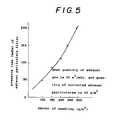
- Figs. 4 and 5show the characteristics of the felt-like bodies.
- the ratio of voids of the exhaust particulate filter risethe collecting efficiency of the exhaust particulates lowers.
- the pressure loss of the exhaust particulate filterincreases. It is desired that presently allowable pressure loss of the exhaust particulate filter in the diesel engine is about 150 mmHg, and the collecting efficiency of the exhaust particulates is 50% or more.
- the felt-like body formed of inorganic lengthy fibers according to the present inventionis high in the ratio of voids, less pressure loss occurred, and the collecting efficiency of the exhaust particulates was about 90%.
- the exhaust particulatesare collected even in the portion internally of the whole surface of the exhaust particulate filter, which is different from the conventional honeycomb type in which the exhaust particulates are collected only in the surface. Since the exhaust particulates can be collected not only from the surface but also from the interior, the surface area of the exhaust particulate filter can be made approximately 1/3 as narrow as that of the conventional honeycomb type.
- the aforementioned exhaust particulate filterwas used to repeatedly collect the exhaust particulates, and the reproduction thereof was carried out. As a result, it has been made sure that even in repeated (500 times) tests, the reproduction with complete combustion of exhaust particulates was obtained, no pressure loss occurred, and 90% of collecting efficiency of the exhaust particulates could be maintained. This was excellent as compared with 50% of collecting efficiency obtained by the conventional exhaust particulate filter.
- the present inventionprovides an exhaust particulate filter for a diesel engine in which wire nets formed of heat resistant metal are put upon both upper and lower surfaces of a felt-like body, which are arrested from both the surfaces thereof by heat resistant yarn, said felt-like body being configured such that heat resistant inorganic lengthy fibers cut into a predetermined length are irregularly oriented in a horizontal direction and laminated to which needles are applied and said inorganic lengthy fibers are vertically entangled. Therefore, the particulates are collected not only from the surface but from the interior of the felt-like body formed of the inorganic lengthy fibers, whereby the collecting efficiency of the exhaust particulates is high and the pressure loss is small.
Landscapes
- Engineering & Computer Science (AREA)
- Chemical & Material Sciences (AREA)
- Chemical Kinetics & Catalysis (AREA)
- General Engineering & Computer Science (AREA)
- Combustion & Propulsion (AREA)
- Mechanical Engineering (AREA)
- Life Sciences & Earth Sciences (AREA)
- Geology (AREA)
- Inorganic Chemistry (AREA)
- Ceramic Engineering (AREA)
- Physics & Mathematics (AREA)
- Geometry (AREA)
- Processes For Solid Components From Exhaust (AREA)
- Filtering Materials (AREA)
Description
Claims (2)
- An exhaust particulate filter for a diesel engine,comprising:a tubular exhaust body having an exhaust inlet and anexhaust outlet;a first tubular filter body (22) mounted within the tubularexhaust body, the first tubular filter body comprising a felt-likebody having heat resistant inorganic lengthy fibers cut intoa predetermined length, irregularly orientated in a horizontaldirection and laminated, said inorganic lengthy fibers beingvertically entangled by applying needles, characterised in thatthe exhaust particulate filter further comprises:wire nets formed of heat resistant metal on both inner andouter surfaces of the felt-like body, the wire nets beingarrested with said filter-like body by heat resistant yarn;a second tubular filter body (16) coaxially disposed withinthe first tubular filter body (22);a bulk head tube (23) coaxially disposed between the firstand second tubular filter bodies;a sensor (55) disposed proximate to the exhaust inlet todetect the exhaust flow rate and pressure in the exhaust inlet;a valve for controlling the proportion of the exhaust gaswhich in use is caused to pass through the first filter body;at least one electrode for electrically energizing at leastone of the wire nets thereby to burn particulate materialcollected thereon; andcontrol means (53,54) for opening the valve when the exhaustflow rate detected by the sensor exceeds a predetermined level,and for energising the at least one electrode responsive todetection of exhaust gas pressure in the filter.
- The exhaust particulate filter for a diesel engine accordingto claim 1, wherein said inorganic lengthy fibers are such formedthat at least one out of silicon carbide, aluminum and aluminais coated to the surface of the fiber selected out of Si-Ti-C-Oceramics, S-C-O ceramics, Si-N ceramics, Si-O ceramics and metal.
Applications Claiming Priority (2)
| Application Number | Priority Date | Filing Date | Title |
|---|---|---|---|
| JP6114131AJP2732031B2 (en) | 1994-04-28 | 1994-04-28 | Exhaust particulate filter for diesel engine |
| JP114131/94 | 1994-04-28 |
Publications (3)
| Publication Number | Publication Date |
|---|---|
| EP0679799A2 EP0679799A2 (en) | 1995-11-02 |
| EP0679799A3 EP0679799A3 (en) | 1996-03-27 |
| EP0679799B1true EP0679799B1 (en) | 1998-07-01 |
Family
ID=14629919
Family Applications (1)
| Application Number | Title | Priority Date | Filing Date |
|---|---|---|---|
| EP95302736AExpired - LifetimeEP0679799B1 (en) | 1994-04-28 | 1995-04-24 | Exhaust particulate filter for diesel engine |
Country Status (4)
| Country | Link |
|---|---|
| US (1) | US5560757A (en) |
| EP (1) | EP0679799B1 (en) |
| JP (1) | JP2732031B2 (en) |
| DE (2) | DE679799T1 (en) |
Families Citing this family (26)
| Publication number | Priority date | Publication date | Assignee | Title |
|---|---|---|---|---|
| US5611832A (en)* | 1994-09-21 | 1997-03-18 | Isuzu Ceramics Research Institute Co., Ltd. | Diesel particulate filter apparatus |
| JP3161672B2 (en) | 1994-11-25 | 2001-04-25 | 株式会社いすゞセラミックス研究所 | Exhaust particulate filter |
| US5682740A (en)* | 1995-05-12 | 1997-11-04 | Isuzu Ceramics Research Institute Co., Ltd. | Diesel particulate filter apparatus |
| JPH0949421A (en)* | 1995-05-30 | 1997-02-18 | Sumitomo Electric Ind Ltd | Particulate trap for diesel engine |
| UA67719C2 (en)* | 1995-11-08 | 2004-07-15 | Shell Int Research | Deformable well filter and method for its installation |
| US5782941A (en)* | 1996-09-23 | 1998-07-21 | Sumitomo Electric Industries, Ltd. | Particulate trap for diesel engine |
| DE19741498B4 (en)* | 1997-09-20 | 2008-07-03 | Evonik Degussa Gmbh | Production of a ceramic stainless steel mesh composite |
| US6244918B1 (en)* | 1999-10-18 | 2001-06-12 | Robert Malcolm Cameron | Noise muffler-exhaust filter for a marine engine |
| DE10016841A1 (en)* | 2000-04-05 | 2001-10-18 | Drafas Gmbh | Formable mesh fabric composite |
| US20020195388A1 (en)* | 2001-05-22 | 2002-12-26 | Sierens Stephen E. | Advanced leaf disc filter segment |
| JP2002371823A (en)* | 2001-06-19 | 2002-12-26 | Mitsui Eng & Shipbuild Co Ltd | Diesel engine exhaust gas purification equipment |
| WO2003018170A1 (en)* | 2001-08-22 | 2003-03-06 | Parker-Hannifin Corporation | High capacity depth filter bag |
| DE10206805A1 (en) | 2002-02-19 | 2003-08-28 | Bosch Gmbh Robert | Soot filter for cleaning I.C. engine exhaust gases, has device for reducing exhaust gas counter pressure with predetermined breaking point in filter body of filter and/or in by-pass line of filter |
| US20030155293A1 (en)* | 2002-02-21 | 2003-08-21 | Mcgrath James A. | Square-holed spiral welded filter element support sleeve |
| US6743355B2 (en)* | 2002-09-11 | 2004-06-01 | Delphi Technologies, Inc. | Heated fuel strainer assembly |
| SE527115C2 (en)* | 2003-04-14 | 2005-12-27 | Scania Cv Abp | Method and apparatus for a particulate filter for an exhaust system, silencer containing such a device and an internal combustion engine-driven vehicle |
| US7506504B2 (en)* | 2005-12-21 | 2009-03-24 | Basf Catalysts Llc | DOC and particulate control system for diesel engines |
| JP4885649B2 (en)* | 2006-03-10 | 2012-02-29 | イビデン株式会社 | Sheet material and exhaust gas purification device |
| EP2411142B1 (en)* | 2009-02-27 | 2016-11-16 | Inventys Thermal Technologies Inc. | Parallel passage fluid contactor structure |
| JPWO2010143608A1 (en)* | 2009-06-08 | 2012-11-22 | 株式会社超高温材料研究センター | COMPOSITE INORGANIC FIBER AND METHOD FOR PRODUCING SAME, AND COMPOSITE INORGANIC FIBER PRODUCT AND METHOD FOR PRODUCING SAME |
| JP2016153737A (en)* | 2015-02-20 | 2016-08-25 | いすゞ自動車株式会社 | Sensor |
| JP2016153610A (en)* | 2015-02-20 | 2016-08-25 | いすゞ自動車株式会社 | Exhaust emission control device |
| CN105257370A (en)* | 2015-10-08 | 2016-01-20 | 南京依柯卡特汽车催化器有限公司 | Purifier on the basis of solving black smoke emission of diesel engine |
| EP3423689A1 (en)* | 2016-03-02 | 2019-01-09 | Watlow Electric Manufacturing Company | Virtual sensing system |
| CN109505681B (en)* | 2019-01-18 | 2024-10-22 | 任丘市本溪石油设备有限公司 | Black smoke purifying device of high-power diesel engine of workover rig |
| CN114352380B (en)* | 2022-01-10 | 2022-12-02 | 岚士智能科技(上海)有限公司 | Processing method and equipment of silicon carbide DPF |
Family Cites Families (24)
| Publication number | Priority date | Publication date | Assignee | Title |
|---|---|---|---|---|
| US2821261A (en)* | 1957-05-27 | 1958-01-28 | Leslie F Vixler | Method and means for filtering gas |
| FR87613E (en)* | 1964-11-05 | 1966-04-15 | Berliet Automobiles | Device for cleaning the exhaust gases of heat engines containing solid components |
| US3871850A (en)* | 1973-03-20 | 1975-03-18 | Ethyl Corp | Filter element |
| US3960509A (en)* | 1974-12-30 | 1976-06-01 | Abriany Raymond R | Catalytic muffler |
| BR7805030A (en)* | 1977-11-07 | 1979-05-29 | Texaco Development Corp | FILTER AND PROCESS FOR TREATING A HOT EXHAUST GAS CHAIN |
| NL7812241A (en)* | 1977-12-24 | 1979-06-26 | Breveteam Sa | FLAT, FLEXIBLE LAYERED BODY FOR TREATING GASES OR LIQUIDS AS WELL AS A PROCEDURE FOR MANUFACTURING SUCH A BODY. |
| US4255173A (en)* | 1977-12-27 | 1981-03-10 | Texaco Inc. | Lead filter for internal combustion engine exhaust gases |
| US4181514A (en)* | 1978-02-14 | 1980-01-01 | Huyck Corporation | Stitch knitted filters for high temperature fluids and method of making them |
| JPS56141723U (en)* | 1980-03-28 | 1981-10-26 | ||
| JPS57163112A (en)* | 1981-03-31 | 1982-10-07 | Toyota Motor Corp | Device for disposing particles in exhaust gas of diesel engine and method for manufacturing the same |
| DE3228325A1 (en)* | 1982-07-29 | 1984-02-02 | Fa. J. Eberspächer, 7300 Esslingen | FILTER AND AFTER COMBUSTION DEVICE |
| EP0216729B1 (en)* | 1985-08-16 | 1990-10-24 | Alusuisse-Lonza Services Ag | Filter plug for cleaning exhaust gases from diesel engines |
| DE3623786A1 (en)* | 1985-11-13 | 1987-05-14 | Man Technologie Gmbh | METHOD FOR PRODUCING SOOT FILTERS |
| GB8605058D0 (en)* | 1986-02-28 | 1986-04-09 | Porous Element Heating Ltd | Removal of particulate material from gas |
| DE3622623A1 (en)* | 1986-07-05 | 1988-01-14 | Man Nutzfahrzeuge Gmbh | METHOD AND DEVICE FOR ELIMINATING SOOT SEPARATED IN AN EXHAUST FILTER OF AN INTERNAL COMBUSTION ENGINE |
| US4813231A (en)* | 1987-10-07 | 1989-03-21 | Southwest Research Institute | Engine exhaust after-treatment device |
| IT1219270B (en)* | 1988-05-06 | 1990-05-03 | Enea | DEVICE FOR THE REDUCTION OF ATMOSPHERIC POLLUTION FROM EXHAUST GAS OF INTERNAL COMBUSTION ENGINES |
| JPH03118814A (en)* | 1989-10-02 | 1991-05-21 | Yunitsukusu:Kk | Porous aluminum combined material and production thereof |
| US5248482A (en)* | 1991-04-05 | 1993-09-28 | Minnesota Mining And Manufacturing Company | Diesel particulate trap of perforated tubes wrapped with cross-wound inorganic yarn to form four-sided filter traps |
| US5171341A (en)* | 1991-04-05 | 1992-12-15 | Minnesota Mining And Manufacturing Company | Concentric-tube diesel particulate filter |
| US5228891A (en)* | 1992-01-07 | 1993-07-20 | Pall Corporation | Regenerable diesel exhaust filter |
| US5248481A (en)* | 1992-05-11 | 1993-09-28 | Minnesota Mining And Manufacturing Company | Diesel particulate trap of perforated tubes having laterally offset cross-wound wraps of inorganic yarn |
| WO1994007588A1 (en)* | 1992-09-25 | 1994-04-14 | Kabushiki Kaisha Toyoda Jidoshokki Seisakusho | Heat-resistant filter |
| US5298046A (en)* | 1993-01-06 | 1994-03-29 | Minnesota Mining And Manufacturing Company | Diesel particulate filter element and filter |
- 1994
- 1994-04-28JPJP6114131Apatent/JP2732031B2/ennot_activeExpired - Lifetime
- 1995
- 1995-04-24EPEP95302736Apatent/EP0679799B1/ennot_activeExpired - Lifetime
- 1995-04-24DEDE0679799Tpatent/DE679799T1/enactivePending
- 1995-04-24DEDE69503176Tpatent/DE69503176T2/ennot_activeExpired - Fee Related
- 1995-04-26USUS08/429,132patent/US5560757A/ennot_activeExpired - Fee Related
Also Published As
| Publication number | Publication date |
|---|---|
| EP0679799A3 (en) | 1996-03-27 |
| DE69503176D1 (en) | 1998-08-06 |
| EP0679799A2 (en) | 1995-11-02 |
| DE69503176T2 (en) | 1999-01-07 |
| US5560757A (en) | 1996-10-01 |
| JPH07289830A (en) | 1995-11-07 |
| JP2732031B2 (en) | 1998-03-25 |
| DE679799T1 (en) | 1996-10-10 |
Similar Documents
| Publication | Publication Date | Title |
|---|---|---|
| EP0679799B1 (en) | Exhaust particulate filter for diesel engine | |
| EP0687805B1 (en) | Diesel particulate filter | |
| US5651250A (en) | Diesel particulate filter apparatus | |
| US5298046A (en) | Diesel particulate filter element and filter | |
| EP0699827B1 (en) | Diesel particulate filter apparatus | |
| US5171341A (en) | Concentric-tube diesel particulate filter | |
| EP1580410B1 (en) | Device for removing particle in exhaust gas | |
| JP2005507476A (en) | Open-type particle filter with heating device | |
| EP0834004A1 (en) | Self supporting hot gas filter assembly | |
| JPH0868313A (en) | Control device for diesel particulate filter | |
| JP2964120B2 (en) | Diesel particulate filter | |
| JP2918450B2 (en) | Filter structure in diesel particulate filter | |
| JP2003172117A (en) | Exhaust gas purifier with two types of ceramic nonwoven fabric | |
| JP3075668B2 (en) | Filter structure in diesel particulate filter | |
| JPH07293223A (en) | Exhaust emission control device for diesel engine | |
| JP3391160B2 (en) | Exhaust particulate processing equipment for internal combustion engines | |
| JPH0868310A (en) | Diesel particulate filter device | |
| JPH06108823A (en) | Heat-resistant cylindrical filter | |
| JP2002349230A (en) | Exhaust emission control device | |
| EP0578772B1 (en) | Concentric-tube diesel particulate filter | |
| JP3438316B2 (en) | Exhaust gas purification device | |
| JP3199965B2 (en) | Exhaust particulate filter for diesel engine | |
| JPH07310532A (en) | Diesel particulate filter | |
| JPH06117216A (en) | Tubular filter device | |
| JPH07286510A (en) | Diesel particulate filter |
Legal Events
| Date | Code | Title | Description |
|---|---|---|---|
| PUAI | Public reference made under article 153(3) epc to a published international application that has entered the european phase | Free format text:ORIGINAL CODE: 0009012 | |
| AK | Designated contracting states | Kind code of ref document:A2 Designated state(s):DE FR GB | |
| PUAL | Search report despatched | Free format text:ORIGINAL CODE: 0009013 | |
| EL | Fr: translation of claims filed | ||
| 17P | Request for examination filed | Effective date:19960112 | |
| AK | Designated contracting states | Kind code of ref document:A3 Designated state(s):DE FR GB | |
| DET | De: translation of patent claims | ||
| 17Q | First examination report despatched | Effective date:19970210 | |
| GRAG | Despatch of communication of intention to grant | Free format text:ORIGINAL CODE: EPIDOS AGRA | |
| GRAG | Despatch of communication of intention to grant | Free format text:ORIGINAL CODE: EPIDOS AGRA | |
| GRAH | Despatch of communication of intention to grant a patent | Free format text:ORIGINAL CODE: EPIDOS IGRA | |
| GRAH | Despatch of communication of intention to grant a patent | Free format text:ORIGINAL CODE: EPIDOS IGRA | |
| GRAA | (expected) grant | Free format text:ORIGINAL CODE: 0009210 | |
| AK | Designated contracting states | Kind code of ref document:B1 Designated state(s):DE FR GB | |
| REF | Corresponds to: | Ref document number:69503176 Country of ref document:DE Date of ref document:19980806 | |
| ET | Fr: translation filed | ||
| PLBE | No opposition filed within time limit | Free format text:ORIGINAL CODE: 0009261 | |
| STAA | Information on the status of an ep patent application or granted ep patent | Free format text:STATUS: NO OPPOSITION FILED WITHIN TIME LIMIT | |
| 26N | No opposition filed | ||
| PGFP | Annual fee paid to national office [announced via postgrant information from national office to epo] | Ref country code:FR Payment date:20010328 Year of fee payment:7 | |
| PGFP | Annual fee paid to national office [announced via postgrant information from national office to epo] | Ref country code:GB Payment date:20010418 Year of fee payment:7 | |
| PGFP | Annual fee paid to national office [announced via postgrant information from national office to epo] | Ref country code:DE Payment date:20010525 Year of fee payment:7 | |
| REG | Reference to a national code | Ref country code:GB Ref legal event code:IF02 | |
| PG25 | Lapsed in a contracting state [announced via postgrant information from national office to epo] | Ref country code:GB Free format text:LAPSE BECAUSE OF NON-PAYMENT OF DUE FEES Effective date:20020424 | |
| PG25 | Lapsed in a contracting state [announced via postgrant information from national office to epo] | Ref country code:DE Free format text:LAPSE BECAUSE OF NON-PAYMENT OF DUE FEES Effective date:20021101 | |
| GBPC | Gb: european patent ceased through non-payment of renewal fee | Effective date:20020424 | |
| PG25 | Lapsed in a contracting state [announced via postgrant information from national office to epo] | Ref country code:FR Free format text:LAPSE BECAUSE OF NON-PAYMENT OF DUE FEES Effective date:20021231 | |
| REG | Reference to a national code | Ref country code:FR Ref legal event code:ST |