EP0679565B1 - Front end of an automobile - Google Patents
Front end of an automobileDownload PDFInfo
- Publication number
- EP0679565B1 EP0679565B1EP95400909AEP95400909AEP0679565B1EP 0679565 B1EP0679565 B1EP 0679565B1EP 95400909 AEP95400909 AEP 95400909AEP 95400909 AEP95400909 AEP 95400909AEP 0679565 B1EP0679565 B1EP 0679565B1
- Authority
- EP
- European Patent Office
- Prior art keywords
- rigid
- moulds
- vehicle
- crossmember
- plastic
- Prior art date
- Legal status (The legal status is an assumption and is not a legal conclusion. Google has not performed a legal analysis and makes no representation as to the accuracy of the status listed.)
- Expired - Lifetime
Links
- 239000004033plasticSubstances0.000claimsabstractdescription21
- 229920003023plasticPolymers0.000claimsabstractdescription21
- 238000000034methodMethods0.000claimsdescription18
- 238000004519manufacturing processMethods0.000claimsdescription4
- 230000000149penetrating effectEffects0.000claimsdescription2
- 238000000465mouldingMethods0.000abstractdescription2
- 230000000712assemblyEffects0.000abstract4
- 238000000429assemblyMethods0.000abstract4
- 239000000463materialSubstances0.000description7
- 238000005452bendingMethods0.000description3
- 229910052751metalInorganic materials0.000description3
- 239000002184metalSubstances0.000description3
- 239000000835fiberSubstances0.000description2
- LQLQDKBJAIILIQ-UHFFFAOYSA-NDibutyl terephthalateChemical compoundCCCCOC(=O)C1=CC=C(C(=O)OCCCC)C=C1LQLQDKBJAIILIQ-UHFFFAOYSA-N0.000description1
- 239000004952PolyamideSubstances0.000description1
- 229910052782aluminiumInorganic materials0.000description1
- XAGFODPZIPBFFR-UHFFFAOYSA-NaluminiumChemical compound[Al]XAGFODPZIPBFFR-UHFFFAOYSA-N0.000description1
- 239000011324beadSubstances0.000description1
- 230000015572biosynthetic processEffects0.000description1
- 230000000694effectsEffects0.000description1
- WOLATMHLPFJRGC-UHFFFAOYSA-Nfuran-2,5-dione;styreneChemical compoundO=C1OC(=O)C=C1.C=CC1=CC=CC=C1WOLATMHLPFJRGC-UHFFFAOYSA-N0.000description1
- 238000005304joiningMethods0.000description1
- 238000010137moulding (plastic)Methods0.000description1
- 229920002647polyamidePolymers0.000description1
- 239000012783reinforcing fiberSubstances0.000description1
- 238000003466weldingMethods0.000description1
Images


Classifications
- B—PERFORMING OPERATIONS; TRANSPORTING
- B62—LAND VEHICLES FOR TRAVELLING OTHERWISE THAN ON RAILS
- B62D—MOTOR VEHICLES; TRAILERS
- B62D29/00—Superstructures, understructures, or sub-units thereof, characterised by the material thereof
- B62D29/001—Superstructures, understructures, or sub-units thereof, characterised by the material thereof characterised by combining metal and synthetic material
- B—PERFORMING OPERATIONS; TRANSPORTING
- B29—WORKING OF PLASTICS; WORKING OF SUBSTANCES IN A PLASTIC STATE IN GENERAL
- B29C—SHAPING OR JOINING OF PLASTICS; SHAPING OF MATERIAL IN A PLASTIC STATE, NOT OTHERWISE PROVIDED FOR; AFTER-TREATMENT OF THE SHAPED PRODUCTS, e.g. REPAIRING
- B29C45/00—Injection moulding, i.e. forcing the required volume of moulding material through a nozzle into a closed mould; Apparatus therefor
- B29C45/14—Injection moulding, i.e. forcing the required volume of moulding material through a nozzle into a closed mould; Apparatus therefor incorporating preformed parts or layers, e.g. injection moulding around inserts or for coating articles
- B29C45/14336—Coating a portion of the article, e.g. the edge of the article
- B—PERFORMING OPERATIONS; TRANSPORTING
- B29—WORKING OF PLASTICS; WORKING OF SUBSTANCES IN A PLASTIC STATE IN GENERAL
- B29C—SHAPING OR JOINING OF PLASTICS; SHAPING OF MATERIAL IN A PLASTIC STATE, NOT OTHERWISE PROVIDED FOR; AFTER-TREATMENT OF THE SHAPED PRODUCTS, e.g. REPAIRING
- B29C45/00—Injection moulding, i.e. forcing the required volume of moulding material through a nozzle into a closed mould; Apparatus therefor
- B29C45/16—Making multilayered or multicoloured articles
- B29C45/1671—Making multilayered or multicoloured articles with an insert
- B—PERFORMING OPERATIONS; TRANSPORTING
- B62—LAND VEHICLES FOR TRAVELLING OTHERWISE THAN ON RAILS
- B62D—MOTOR VEHICLES; TRAILERS
- B62D25/00—Superstructure or monocoque structure sub-units; Parts or details thereof not otherwise provided for
- B62D25/08—Front or rear portions
- B62D25/082—Engine compartments
- B62D25/084—Radiator supports
- B—PERFORMING OPERATIONS; TRANSPORTING
- B62—LAND VEHICLES FOR TRAVELLING OTHERWISE THAN ON RAILS
- B62D—MOTOR VEHICLES; TRAILERS
- B62D29/00—Superstructures, understructures, or sub-units thereof, characterised by the material thereof
- B62D29/001—Superstructures, understructures, or sub-units thereof, characterised by the material thereof characterised by combining metal and synthetic material
- B62D29/004—Superstructures, understructures, or sub-units thereof, characterised by the material thereof characterised by combining metal and synthetic material the metal being over-moulded by the synthetic material, e.g. in a mould
- B—PERFORMING OPERATIONS; TRANSPORTING
- B29—WORKING OF PLASTICS; WORKING OF SUBSTANCES IN A PLASTIC STATE IN GENERAL
- B29C—SHAPING OR JOINING OF PLASTICS; SHAPING OF MATERIAL IN A PLASTIC STATE, NOT OTHERWISE PROVIDED FOR; AFTER-TREATMENT OF THE SHAPED PRODUCTS, e.g. REPAIRING
- B29C45/00—Injection moulding, i.e. forcing the required volume of moulding material through a nozzle into a closed mould; Apparatus therefor
- B29C45/17—Component parts, details or accessories; Auxiliary operations
- B29C45/26—Moulds
- B29C2045/2683—Plurality of independent mould cavities in a single mould
- B—PERFORMING OPERATIONS; TRANSPORTING
- B29—WORKING OF PLASTICS; WORKING OF SUBSTANCES IN A PLASTIC STATE IN GENERAL
- B29K—INDEXING SCHEME ASSOCIATED WITH SUBCLASSES B29B, B29C OR B29D, RELATING TO MOULDING MATERIALS OR TO MATERIALS FOR MOULDS, REINFORCEMENTS, FILLERS OR PREFORMED PARTS, e.g. INSERTS
- B29K2705/00—Use of metals, their alloys or their compounds, for preformed parts, e.g. for inserts
- B—PERFORMING OPERATIONS; TRANSPORTING
- B29—WORKING OF PLASTICS; WORKING OF SUBSTANCES IN A PLASTIC STATE IN GENERAL
- B29L—INDEXING SCHEME ASSOCIATED WITH SUBCLASS B29C, RELATING TO PARTICULAR ARTICLES
- B29L2031/00—Other particular articles
- B29L2031/30—Vehicles, e.g. ships or aircraft, or body parts thereof
- B29L2031/3002—Superstructures characterized by combining metal and plastics, i.e. hybrid parts
Definitions
- the present inventionrelates to a technical front face of motor vehicle.
- a technical front panel of a motor vehicleis a part which is intended to be installed at the front of the vehicle, general directly on its chassis, to support both headlight optics, the hood safety hooking system, possibly the radiator grille, as well as other parts of the vehicle such as a radiator or fan.
- the technical front panelhas good overall rigidity, and is particularly resistant in its region connecting the hood attachment point to the vehicle chassis.
- hood attachment functionconstituting a important element of vehicle safety, it is essential that the technical front panel offers optimal resistance to any effort hood removal.
- any technical front panelmust leave free a central passage corresponding to the dimensions of the radiator, so that the hood hooking point, which is also in the central area, is located above the recess of the technical front panel.
- the region of the technical front panel connecting the hood attachment point to vehicle chassisis not straight but follows the outline of the central passage. Therefore, in if the hood is torn off, it not only undergoes stresses traction but also significant bending forces.
- the relatively large dimensions of the technical front panelscan induce internal stresses in the molded parts, which also have a poor dimensional stability due to large expansions of the plastic.
- Such a technical front facehas different parts which, to be assembled, require assembly and relatively complex welding that the present invention allows to eliminate.
- the present inventionaims to provide a front face technique which does not have the drawbacks mentioned above and which is furthermore of a particularly simple embodiment and economical.
- the subject of the present inventionis a technical front face motor vehicle comprising at least one rigid cross member, metallic preference, which spans most of its length and at least one plastic support piece subject to the rigid cross member, and capable of receiving at least one vehicle body such as a headlight optic, characterized by fact that it comprises at least two supporting parts made of material plastic and that each support piece is overmolded on a section end of the rigid crossmember.
- the technical front face according to the inventioncan be manufactured for a very low cost price because it is made up of individually inexpensive elements and easy to assemble together to form the technical front panel according to the invention,
- the technical front face according to the inventionis particularly suited to the function hood safety hooking.
- the rigid cross memberis part of the technical front which is able to withstand bending forces important. It can therefore receive the hood attachment point while being secured by its ends to the vehicle chassis.
- the rigid crossmembercan be connected to the vehicle chassis through the end support parts which are then only subjected to tensile forces that they are in able to support, or through the wing supports of the vehicle in the event that said rigid cross member extends over the entire width of the vehicle.
- the technical front panel according to the inventionalso has the advantage of being insensitive to temperature variations, the rigid cross member with a coefficient of expansion close to that of the vehicle chassis, but much lower than that of a plastic, and the supporting parts being sufficiently small to expand only to a small extent.
- the technical front panelhas a first rigid cross member at its part upper and a second rigid crosspiece at its lower part, each of these rigid crosspieces being connected to the support parts in plastic material.
- the present inventionalso relates to a method for create a technical front panel as described above.
- This processis characterized by the fact that there are two molds which each define a support part capable of receiving a vehicle body such as headlight optics, so that said molds are located relative to each other in the position relative of the two support parts of the technical front panel to achieve; that at least one crosspiece is placed between these two molds rigid, preferably metallic, each end of which penetrates into one of the molds; and fill the two molds with material plastic to overmold a support piece on each end of the rigid cross member.
- the method according to the inventionis advantageous in that the spacing of the support parts of the technical front panel as well obtained is fixed by the relative positioning of the two molds, and not by the axial positioning of the rigid crosspiece between these molds.
- cross rigidenters symmetrically in the two molds, said crosspiece rigid which can penetrate more into one of the molds than into the other mold.
- the rigid cross membercan, according to the invention, have an imprecise length, which allows wide dimensional tolerances of manufacture of this cross member, and be placed between the two molds using a simple apparatus which provides only an approximate axial positioning of said crosspiece rigid.
- the two partsare molded at the same time supports so as to reduce the manufacturing time of the face before technique according to the invention.
- the present inventionalso relates to a device to implement the method described above.
- This deviceis characterized by the fact that it comprises two molds which each define a support piece capable of receiving a vehicle body such as a headlight optic, the two molds being arranged so as to be situated in relation to one another in the relative position of the two support parts of the front panel technique to be carried out, each mold being capable of receiving the end a rigid cross member extending between the two molds.
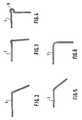
- the technical front panel illustratedhas a crosspiece rigid 1 made of aluminum which has an L-shaped section including examples are shown in Figures 2 to 6.
- the rigid crossmember 1is overmolded at each of its ends by a plastic support part 2 which comprises a housing 3 for receiving a headlight optic 4.
- Each support piece 2further comprises a housing additional 5 to receive for example a flashing light.
- the illustrated technical front panelis intended to be secured to the vehicle chassis by fixing points 6 present in the lower part of each support part 2.
- Fixing lugs 7are also provided in part upper of each support piece 2 to secure the latter to the fender supports of the vehicle.
- the rigid cross member 1comprises, in its central part, a clip 8 of overmolded plastic which is intended to receive the hood safety hook not shown.
- Figures 2, 3 and 4correspond to sleepers rigid extruded.
- the rigid cross member of FIG. 4comprises on its edge a bead 9 directed towards the outside which allows secure the hood safety hook directly to the crossmember rigid without the need to overmold a tie made of material plastic 8 such as that illustrated in FIG. 1.
- the structure of the technical front panel according to the inventionis lends itself particularly well to the safety latching function of the hood.
- the hook safety of the latterexerts on the rigid crossmember 1 a force which is directed upwards and which is transmitted by the rigid crossmember to the plastic support parts 2.
- the rigid cross member 1undergoes then a bending force while the support pieces 2 are not stressed only in traction in their rectilinear part between the end of the rigid cross member 1 and their attachment point 6 on the vehicle chassis.
- plastics usable for producing the support parts 2mention may be made of polyamide, possibly loaded with reinforcing fibers whose function is to limit the thermal expansion of the molded part and increase the temperature resistance, maleic anhydride styrene (SMA) also loaded with fibers, or poly-butyl terephthalate (PBT).
- SMAmaleic anhydride styrene
- PBTpoly-butyl terephthalate
- the rigid cross member 1can further enter one of the support parts 2 than the other part support 2.
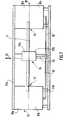
- Figure 7there is shown a device for make the technical front panel of figure 1.
- This devicecomprises two end molds 10, the interior cavities are symmetrical.
- Each interior cavity of a mold 10defines a part support 2.
- the molds 10each consist of two half-molds 10 a , 10 b which are each secured to plates 11 a , 11 b .
- the plate 11 ais able to move in the direction indicated by the double arrow 12 to open or close the molds 10.
- the spacing of the two molds 10is such that their interior cavities are located very precisely in the relative position of the two support pieces 2 of the front face technique to perform.
- the rigid cross member 1can be positioned between the two molds 10 with its ends 13 and 14 penetrating uneven lengths into molds 10.
- the illustrated devicefurther comprises a central mold 15 which is intended to mold the fastener 8 receiving the hook hood security.
- This central mold 15is also constituted by a half-mold 15 a secured to the movable plate 11 a and a half-mold 15 b secured to the fixed plate 11 b .
- Supply channels 16make it possible to inject plastic in the three molds 10 and 15 for overmolding simultaneously the two support pieces 2 and the safety clip of the cover 8, in order to obtain a manufacturing cycle for the front face particularly short technique.
- the parts plastic supportscan be molded individually and then attached to the rigid crossmember to which they are secured mechanically.
- the mechanical joining means that can be used for this effectcan be of any known type.
- the cross member rigidextends to the wing supports, i.e. over the entire width of the vehicle.
- This embodimenthas the advantage of allowing the direct fixing of the rigid crossmember on the wing supports.
- the rigid cross memberis made of a relatively expensive material, it may be preferable, as in the embodiment illustrated in the drawing, to limit the length of said rigid cross member to reduce the cost price of the technical front panel according to the invention.
- FIG. 8represents another embodiment of the invention in which the support parts 2 'of the front face technical extend in the lower part where they are subject to a second rigid cross member 17.
- Fixing lugs 18are provided on the crosspiece rigid 17 to receive the lower part of a radiator 19, the upper part is intended to be fixed to the rigid crossmember superior 1.
- the support parts 2 'furtherinclude tabs 20 able to support a fan 21 located in front of the radiator 19.
- the relative positioning of the two support pieces 2 'is preferably provided by overmolding support parts 2 'simultaneously on the rigid crosspieces 1 and 17.
- one of the support piecesincludes a lock to serve as a point for hanging the cover while the other support part includes the hood safety hook.
- the security lock and hookcan advantageously be molded in each support piece.
Landscapes
- Engineering & Computer Science (AREA)
- Mechanical Engineering (AREA)
- Chemical & Material Sciences (AREA)
- Combustion & Propulsion (AREA)
- Transportation (AREA)
- Structural Engineering (AREA)
- Architecture (AREA)
- Manufacturing & Machinery (AREA)
- Body Structure For Vehicles (AREA)
- Arrangement Or Mounting Of Propulsion Units For Vehicles (AREA)
- Motor Or Generator Cooling System (AREA)
- Automatic Cycles, And Cycles In General (AREA)
- Lighting Device Outwards From Vehicle And Optical Signal (AREA)
Abstract
Description
Translated fromFrenchLa présente invention concerne une face avant technique devéhicule automobile.The present invention relates to a technical front face ofmotor vehicle.
Une face avant technique de véhicule automobile est unepièce qui est destinée à être installée à l'avant du véhicule, engénéral directement sur son châssis, pour supporter à la fois lesoptiques de phares, le système d'accrochage de sécurité du capot,éventuellement la calandre, ainsi que d'autres organes du véhiculetels qu'un radiateur ou un ventilateur.A technical front panel of a motor vehicle is apart which is intended to be installed at the front of the vehicle,general directly on its chassis, to support bothheadlight optics, the hood safety hooking system,possibly the radiator grille, as well as other parts of the vehiclesuch as a radiator or fan.
Ces fonctions requièrent que la face avant techniqueprésente une bonne rigidité d'ensemble, et soit particulièrementrésistante dans sa région reliant le point d'accrochage du capot auchâssis du véhicule.These functions require that the technical front panelhas good overall rigidity, and is particularlyresistant in its region connecting the hood attachment point to thevehicle chassis.
En effet, la fonction d'accrochage du capot constituant unélément important de la sécurité du véhicule, il est primordial que laface avant technique offre une résistance optimale à tout effortd'arrachement du capot.Indeed, the hood attachment function constituting aimportant element of vehicle safety, it is essential that thetechnical front panel offers optimal resistance to any efforthood removal.
Or, du fait de la présence du radiateur à l'avant du moteurde la plupart des véhicules automobiles, toute face avant techniquedoit laisser libre un passage central correspondant aux dimensions duradiateur, de sorte que le point d'accrochage du capot, qui estégalement dans la zone centrale, se situe au-dessus de l'évidement dela face avant technique.However, due to the presence of the radiator at the front of the enginemost motor vehicles, any technical front panelmust leave free a central passage corresponding to the dimensions of theradiator, so that the hood hooking point, which isalso in the central area, is located above the recess ofthe technical front panel.
De ce fait, la région de la face avant technique reliant lepoint d'accrochage du capot au châssis du véhicule n'est pasrectiligne mais suit le contour du passage central. Par conséquent, encas d'arrachement du capot, elle subit non seulement des efforts detraction mais également d'importants efforts de flexion.As a result, the region of the technical front panel connecting thehood attachment point to vehicle chassis is notstraight but follows the outline of the central passage. Therefore, inif the hood is torn off, it not only undergoes stressestraction but also significant bending forces.
On connaít déjà des faces avant techniques constituées parassemblage de pièces en tôle rivetées, vissées ou soudées entre elles.We already know technical front panels constituted byassembly of riveted, screwed or welded sheet metal parts.
Cependant, ces faces avant techniques en tôle présentent lesinconvénients d'être coûteuses en raison notamment du nombred'opérations qui sont nécessaires pour l'assemblage et la fixation despièces entre elles, et de présenter un poids important.However, these sheet metal technical fronts have thedisadvantages of being expensive due in particular to the numberof operations which are necessary for the assembly and fixing of theparts between them, and to present a significant weight.
Pour remédier à ces inconvénients, on a déjà proposé deréaliser des faces avant techniques par moulage de matière plastique,ce qui permet d'obtenir des pièces considérablement plus légères que les faces avant techniques en tôle, et ce, sans aucune opérationd'assemblage.To overcome these drawbacks, it has already been proposed tomake technical front panels by plastic molding,which results in considerably lighter parts thansheet metal technical front panels, without any operationassembly.
Toutefois, la résistance mécanique de telles faces avanttechniques en matière plastique peut s'avérer insuffisante en casd'arrachement du capot.However, the mechanical strength of such front facesplastic techniques may be insufficient in casehood removal.
En outre, les dimensions relativement importantes desfaces avant techniques peuvent induire des contraintes internesdans les pièces moulées, lesquelles présentent par ailleurs unefaible stabilité dimensionnelle du fait des importantes dilatationsthermiques de la matière plastique.In addition, the relatively large dimensions of thetechnical front panels can induce internal stressesin the molded parts, which also have apoor dimensional stability due to large expansionsof the plastic.
Par ailleurs, de DE-A-3 433 935, on connaít une face avanttechnique conforme au préambule de la revendication 1.Furthermore, from DE-A-3 433 935, there is a front facetechnique according to the preamble of claim 1.
Une telle face avant technique comporte différentes piècesqui, pour être assemblées, requièrent des étapes de montage et desoudage relativement complexes que la présente invention permetd'éliminer.Such a technical front face has different partswhich, to be assembled, require assembly andrelatively complex welding that the present invention allowsto eliminate.
La présente invention vise à fournir une face avanttechnique qui ne présente pas les inconvénients rappelés ci-dessuset qui est en outre d'un mode de réalisation particulièrement simpleet économique.The present invention aims to provide a front facetechnique which does not have the drawbacks mentioned aboveand which is furthermore of a particularly simple embodimentand economical.
La présente invention a pour objet une face avant techniquede véhicule automobile comportant au moins une traverse rigide, depréférence métallique, qui s'étend sur la majeure partie de salongueur et au moins une pièce-support en matière plastiqueassujettie à la traverse rigide, et apte à recevoir au moins unorgane du véhicule tel qu'une optique de phare, caractérisé par lefait qu'elle comporte au moins deux pièces-supports en matièreplastique et que, chaque pièce-support est surmoulée sur un tronçond'extrémité de la traverse rigide.The subject of the present invention is a technical front facemotor vehicle comprising at least one rigid cross member,metallic preference, which spans most of itslength and at least one plastic support piecesubject to the rigid cross member, and capable of receiving at least onevehicle body such as a headlight optic, characterized byfact that it comprises at least two supporting parts made of materialplastic and that each support piece is overmolded on a sectionend of the rigid crossmember.
On comprend que la face avant technique selon l'inventionpeut être fabriquée pour un prix de revient très bas du fait qu'elleest constituée par des éléments individuellement peu coûteux etfaciles à assembler entre eux pour former la face avant techniqueselon l'invention,It is understood that the technical front face according to the inventioncan be manufactured for a very low cost price because itis made up of individually inexpensive elements andeasy to assemble together to form the technical front panelaccording to the invention,
En outre, de par sa structure, la face avant techniqueselon l'invention est particulièrement adaptée à la fonctiond'accrochage de sécurité du capot.In addition, due to its structure, the technical front faceaccording to the invention is particularly suited to the functionhood safety hooking.
En effet, la traverse rigide constitue une partie de laface avant technique qui est apte à supporter des efforts de flexionimportants. Elle peut donc recevoir le point d'accrochage du capottout en étant solidarisée par ses extrémités au châssis du véhicule.Indeed, the rigid cross member is part of thetechnical front which is able to withstand bending forcesimportant. It can therefore receive the hood attachment pointwhile being secured by its ends to the vehicle chassis.
La traverse rigide peut être reliée au châssis du véhiculepar l'intermédiaire des pièces supports d'extrémité lesquelles sontalors uniquement soumises à des efforts de traction qu'elles sont enmesure de supporter, ou par l'intermédiaire des supports d'ailes duvéhicule dans le cas où ladite traverse rigide s'étend sur toute lalargeur du véhicule.The rigid crossmember can be connected to the vehicle chassisthrough the end support parts which arethen only subjected to tensile forces that they are inable to support, or through the wing supports of thevehicle in the event that said rigid cross member extends over the entirewidth of the vehicle.
La face avant technique selon l'invention présente égalementl'avantage d'être peu sensible aux variations de température, latraverse rigide présentant un coefficient de dilatation voisin decelui du châssis du véhicule, mais très inférieur à celui d'unematière plastique, et les pièces supports étant suffisamment petitespour ne se dilater que dans une faible mesure.The technical front panel according to the invention also hasthe advantage of being insensitive to temperature variations, therigid cross member with a coefficient of expansion close tothat of the vehicle chassis, but much lower than that of aplastic, and the supporting parts being sufficiently smallto expand only to a small extent.
Par ailleurs, on peut accroítre la stabilité dimensionnelledes pièces supports d'extrémité en les réalisant en une matièreplastique chargée de fibres, dont le prix de revient assez élevé estcompensé par la relativement petite taille des pièces supports. Cettepetite taille limite d'ailleurs la formation de contraintes internessusceptibles de déformer lesdites pièces supports.In addition, we can increase dimensional stabilityend support parts by making them of a materialfiber-loaded plastic, the cost of which is quite highcompensated by the relatively small size of the supporting parts. Thissmall size also limits the formation of internal stresseslikely to deform said support parts.
Dans un mode de réalisation particulier de l'invention, laface avant technique comporte une première traverse rigide à sa partiesupérieure et une seconde traverse rigide à sa partie inférieure,chacune de ces traverses rigides étant reliée aux pièces supports enmatière plastique.In a particular embodiment of the invention, thetechnical front panel has a first rigid cross member at its partupper and a second rigid crosspiece at its lower part,each of these rigid crosspieces being connected to the support parts inplastic material.
La présente invention a également pour objet un procédé pourréaliser une face avant technique telle que décrite ci-dessus.The present invention also relates to a method forcreate a technical front panel as described above.
Ce procédé est caractérisé par le fait que l'on dispose deuxmoules qui définissent chacun une pièce support apte à recevoir unorgane du véhicule tel qu'une optique de phare, de manière à ce quelesdits moules se situent l'un par rapport à l'autre dans la positionrelative des deux pièces supports de la face avant technique àréaliser; que l'on place entre ces deux moules au moins une traverserigide de préférence métallique dont chaque extrémité pénètre dansl'un des moules; et que l'on remplit les deux moules de matièreplastique pour surmouler une pièce support sur chaque extrémité de latraverse rigide.This process is characterized by the fact that there are twomolds which each define a support part capable of receiving avehicle body such as headlight optics, so thatsaid molds are located relative to each other in the positionrelative of the two support parts of the technical front panel toachieve; that at least one crosspiece is placed between these two moldsrigid, preferably metallic, each end of which penetrates intoone of the molds; and fill the two molds with materialplastic to overmold a support piece on each end of therigid cross member.
Le procédé selon l'invention est avantageux en ce quel'écartement des pièces supports de la face avant technique ainsi obtenue est fixée par le positionnement relatif des deux moules, etnon par le positionnement axial de la traverse rigide entre ces moules.The method according to the invention is advantageous in thatthe spacing of the support parts of the technical front panel as wellobtained is fixed by the relative positioning of the two molds, andnot by the axial positioning of the rigid crosspiece between these molds.
En d'autres termes, il n'est pas nécessaire que la traverserigide pénètre symétriquement dans les deux moules, ladite traverserigide pouvant pénétrer davantage dans l'un des moules que dansl'autre moule.In other words, it is not necessary that the crossrigid enters symmetrically in the two molds, said crosspiecerigid which can penetrate more into one of the molds than intothe other mold.
De ce fait, la traverse rigide peut, selon l'invention,présenter une longueur peu précise, ce qui autorise de largestolérances dimensionnelles de fabrication de cette traverse, et êtreplacée entre les deux moules à l'aide d'un appareillage simple quin'assure qu'un positionnement axial approximatif de ladite traverserigide.Therefore, the rigid cross member can, according to the invention,have an imprecise length, which allows widedimensional tolerances of manufacture of this cross member, and beplaced between the two molds using a simple apparatus whichprovides only an approximate axial positioning of said crosspiecerigid.
Avantageusement, on surmoule en même temps les deux piècessupports de manière à diminuer le temps de fabrication de la faceavant technique selon l'invention.Advantageously, the two parts are molded at the same timesupports so as to reduce the manufacturing time of the facebefore technique according to the invention.
La présente invention a également pour objet un dispositifpour mettre en oeuvre le procédé décrit ci-dessus.The present invention also relates to a deviceto implement the method described above.
Ce dispositif est caractérisé par le fait qu'il comportedeux moules qui définissent chacun une pièce support apte à recevoirun organe de véhicule tel qu'une optique de phare, les deux moulesétant disposés de manière à se situer l'un par rapport à l'autre dansla position relative des deux pièces supports de la face avanttechnique à réaliser, chaque moule étant apte à recevoir l'extrémitéd'une traverse rigide s'étendant entre les deux moules.This device is characterized by the fact that it comprisestwo molds which each define a support piece capable of receivinga vehicle body such as a headlight optic, the two moldsbeing arranged so as to be situated in relation to one another inthe relative position of the two support parts of the front paneltechnique to be carried out, each mold being capable of receiving the enda rigid cross member extending between the two molds.
Dans le but de mieux faire comprendre l'invention, on va endécrire maintenant un mode de réalisation donné à titre d'exemple nonlimitatif en référence au dessin annexé dans lequel :
- la figure 1 est une vue en perspective d'une face avanttechnique selon un mode de réalisation de l'invention avec deuxoptiques de phare,
- les figures 2 à 6 sont des exemples de coupestransversales de traverses rigides utilisables pour réaliser une faceavant technique selon l'invention,
- la figure 7 est une vue en élévation d'un dispositifpermettant la réalisation de la face avant technique de la figure 1, et
- la figure 8 est une vue analogue à la figure 1 d'une faceavant technique selon un autre mode de réalisation de l'invention.
- FIG. 1 is a perspective view of a technical front face according to an embodiment of the invention with two headlight optics,
- FIGS. 2 to 6 are examples of transverse sections of rigid sleepers which can be used to produce a technical front face according to the invention,
- FIG. 7 is an elevation view of a device allowing the technical front face of FIG. 1 to be produced, and
- Figure 8 is a view similar to Figure 1 of a technical front face according to another embodiment of the invention.
La face avant technique illustrée comporte une traverserigide 1 réalisée en aluminium qui présente une section en L dont desexemples sont représentés sur les figures 2 à 6.The technical front panel illustrated has a crosspiecerigid 1 made of aluminum which has an L-shaped section includingexamples are shown in Figures 2 to 6.
La traverse rigide 1 est surmoulée à chacune de sesextrémités par une pièce support 2 en matière plastique qui comporteun logement 3 pour recevoir une optique de phare 4.The rigid crossmember 1 is overmolded at each of itsends by a
Chaque pièce support 2 comporte en outre un logementsupplémentaire 5 pour recevoir par exemple un feu clignotant.Each
La face avant technique illustrée est destinée à êtreassujettie au châssis du véhicule par des points de fixation 6présents en partie inférieure de chaque pièce support 2.The illustrated technical front panel is intended to besecured to the vehicle chassis by
Des pattes de fixation 7 sont également prévues en partiesupérieure de chaque pièce support 2 pour solidariser ces dernièresaux supports d'ailes du véhicule.
La traverse rigide 1 comporte, dans sa partie centrale, uneattache 8 en matière plastique surmoulée qui est destinée à recevoirle crochet de sécurité du capot non représenté.The rigid cross member 1 comprises, in its central part, a
Sur les exemples de coupes transversales représentés auxfigures 2 à 6, les figures 2, 3 et 4 correspondent à des traversesrigides extrudées.On the examples of cross sections shown inFigures 2 to 6, Figures 2, 3 and 4 correspond to sleepersrigid extruded.
On peut noter que la traverse rigide de la figure 4 comportesur son arête un bourrelet 9 dirigé vers l'extérieur qui permetd'arrimer le crochet de sécurité du capot directement sur la traverserigide sans qu'il soit nécessaire de surmouler une attache en matièreplastique 8 telle que celle illustrée sur la figure 1.It can be noted that the rigid cross member of FIG. 4 compriseson its edge a bead 9 directed towards the outside which allowssecure the hood safety hook directly to the crossmemberrigid without the need to overmold a tie made of
Les coupes des figures 5 et 6 correspondent à des traversesrigides embouties.The sections in Figures 5 and 6 correspond to crosspiecesrigid stamped.
La structure de la face avant technique selon l'invention seprête particulièrement bien à la fonction d'accrochage de sécurité ducapot.The structure of the technical front panel according to the invention islends itself particularly well to the safety latching function of thehood.
En effet, en cas d'arrachement du capot, le crochet desécurité de ce dernier exerce sur la traverse rigide 1 une force quiest dirigée vers le haut et qui est transmise par la traverse rigideaux pièces supports en matière plastique 2. La traverse rigide 1 subitalors un effort de flexion tandis que les pièces supports 2 ne sontsollicitées qu'en traction dans leur partie rectiligne comprise entre l'extrémité de la traverse rigide 1 et leur point d'accrochage 6 surle châssis du véhicule.In fact, if the hood is torn off, the hooksafety of the latter exerts on the rigid crossmember 1 a force whichis directed upwards and which is transmitted by the rigid crossmemberto the
Il en résulte une bonne tenue de la face avant techniqueselon l'invention à l'arrachement du capot.This results in good performance of the technical front panelaccording to the invention when the cover is torn off.
A titre d'exemple de matières plastiques utilisables pourréaliser les pièces supports 2, on peut citer le polyamide,éventuellement chargé de fibres de renfort dont la fonction est delimiter la dilatation thermique de la pièce moulée et d'augmenter latenue en température, le styrène maléique anhydride (SMA)également chargé de fibres, ou encore le poly-butyl téréphtalate(PBT).As an example of plastics usable forproducing the
Conformément à l'invention, il n'est pas nécessaire que lemilieu de la traverse rigide 1 se situe exactement dans le plan médiande la face avant technique.According to the invention, it is not necessary that themiddle of rigid crossmember 1 is exactly in the median planeof the technical front panel.
En d'autres termes, la traverse rigide 1 peut davantagepénétrer dans l'une des pièces supports 2 que dans l'autre piècesupport 2.In other words, the rigid cross member 1 can furtherenter one of the
Cette différence, qui doit toutefois être suffisammentréduite pour ne pas affecter la rigidité d'ensemble de la face avanttechnique selon l'invention, est compensée par la longueur de la zonede surmoulage de chaque pièce support sur la traverse rigide.This difference, which must however be sufficientlyreduced so as not to affect the overall rigidity of the front facetechnique according to the invention, is compensated by the length of the areafor molding each support part on the rigid crossmember.
Dans ces conditions, le positionnement de la traverserigide, lors du surmoulage des deux pièces supports 2, peut êtreeffectué avec une précision relativement faible.Under these conditions, the positioning of the crossrigid, when overmolding the two
Sur la figure 7, on a représenté un dispositif permettant deréaliser la face avant technique de la figure 1.In Figure 7, there is shown a device formake the technical front panel of figure 1.
Ce dispositif comporte deux moules d'extrémité 10 dont lescavités intérieures sont symétriques.This device comprises two
Chaque cavité intérieure d'un moule 10 définit une piècesupport 2.Each interior cavity of a
Les moules 10 sont constitués chacun de deux demi-moules10a, 10b qui sont solidaires chacun de platines 11a, 11b.The
La platine 11a est apte à se déplacer selon la directionindiquée par la double flèche 12 pour ouvrir ou refermer les moules 10.The
Conformément à l'invention, l'écartement des deux moules 10est tel que leurs cavités intérieures se situent très précisément dans la position relative des deux pièces supports 2 de la face avanttechnique à réaliser.According to the invention, the spacing of the two
Dans ces conditions, la traverse rigide 1 peut êtrepositionnée entre les deux moules 10 avec ses extrémités 13 et 14pénétrant sur des longueurs inégales dans les moules 10.Under these conditions, the rigid cross member 1 can bepositioned between the two
En revanche, il est clair que le positionnement transversalde la traverse rigide 1 doit être réalisé avec précision.On the other hand, it is clear that the transverse positioningof the rigid crossmember 1 must be produced with precision.
Le dispositif illustré comporte en outre un moule central 15qui est destiné à surmouler l'attache 8 recevant le crochet desécurité du capot.The illustrated device further comprises a
Ce moule central 15 est également constitué par undemi-moule 15a solidaire de la platine mobile 11a et un demi-moule15b solidaire de la platine fixe 11b.This
Des canaux d'alimentation 16 permettent d'injecter de lamatière plastique dans les trois moules 10 et 15 pour surmoulersimultanément les deux pièces supports 2 et l'attache de sécurité ducapot 8, afin d'obtenir un cycle de fabrication de la face avanttechnique particulièrement court.
En variante, on pourrait prévoir un canal d'alimentationparticulier pour le moule central 15, de manière à réaliser l'attachede sécurité du capot 8 en une autre matière que les deux piècessupports 2. Cette variante autoriserait néanmoins de surmoulersimultanément les pièces supports et l'attache.Alternatively, one could provide a supply channelparticular for the
Dans un autre mode de réalisation non représenté, les piècessupports en matière plastique peuvent être moulées isolément puisrapportées sur la traverse rigide à laquelle elles sont solidariséesmécaniquement.In another embodiment not shown, the partsplastic supports can be molded individually and thenattached to the rigid crossmember to which they are securedmechanically.
Les moyens mécaniques de solidarisation utilisables à ceteffet peuvent être de tout type connu.The mechanical joining means that can be used for thiseffect can be of any known type.
Dans un autre mode de réalisation non illustré, la traverserigide s'étend jusqu'aux supports d'ailes, c'est-à-dire sur toute lalargeur du véhicule.In another embodiment not illustrated, the cross memberrigid extends to the wing supports, i.e. over the entirewidth of the vehicle.
Ce mode de réalisation présente l'avantage de permettre lafixation directe de la traverse rigide sur les supports d'ailes.This embodiment has the advantage of allowing thedirect fixing of the rigid crossmember on the wing supports.
Toutefois, dans l'hypothèse où la traverse rigide estréalisée en un matériau relativement coûteux, il peut être préférable,comme dans le mode de réalisation illustré sur le dessin, de limiter la longueur de ladite traverse rigide pour réduire le prix de revientde la face avant technique selon l'invention.However, if the rigid cross member ismade of a relatively expensive material, it may be preferable,as in the embodiment illustrated in the drawing, to limitthe length of said rigid cross member to reduce the cost priceof the technical front panel according to the invention.
La figure 8 représente un autre mode de réalisation del'invention dans lequel les pièces supports 2' de la face avanttechnique se prolongent en partie inférieure où elles sont assujettiesà une seconde traverse rigide 17.FIG. 8 represents another embodiment ofthe invention in which the support parts 2 'of the front facetechnical extend in the lower part where they are subjectto a second
L'intérêt d'un tel mode de réalisation réside dans le faitque la face avant technique présente une rigidité d'ensemble accrue.The advantage of such an embodiment lies in the factthat the technical front face has increased overall rigidity.
Des pattes de fixation 18 sont prévues sur la traverserigide 17 pour recevoir la partie inférieure d'un radiateur 19 dont lapartie supérieure est destinée à être fixée à la traverse rigidesupérieure 1.Fixing lugs 18 are provided on the crosspiecerigid 17 to receive the lower part of a
Les pièces supports 2' comportent en outre des pattes 20aptes à supporter un ventilateur 21 situé devant le radiateur 19.The support parts 2 'further include
Conformément à l'invention, le positionnement relatif desdeux pièces supports 2' est assuré de préférence par surmoulagesimultané des pièces supports 2' sur les traverses rigides 1 et 17.In accordance with the invention, the relative positioning of thetwo support pieces 2 'is preferably provided by overmoldingsupport parts 2 'simultaneously on the
Dans un autre mode de réalisation non représenté, l'une despièces supports inclut une serrure destinée à servir de pointd'accrochage du capot tandis que l'autre pièce support inclut lecrochet de sécurité du capot. La serrure et le crochet de sécuritépeuvent avantageusement être surmoulés dans chaque pièce support.In another embodiment not shown, one of thesupport pieces includes a lock to serve as a pointfor hanging the cover while the other support part includes thehood safety hook. The security lock and hookcan advantageously be molded in each support piece.
Il est bien entendu que les modes de réalisation quiviennent d'être décrits ne présentent aucun caractère limitatif etqu'ils pourront recevoir toutes modifications désirables sans sortirpour cela du cadre de l'invention.It is understood that the embodiments whichhave just been described have no limiting character andthat they can receive any desirable changes without going outfor this the scope of the invention.
Claims (9)
- Motor vehicle front end comprising at least onerigid crossmember (1, 17) which extends over most of itslength and at least one support piece (2, 2') made ofplastic secured to the rigid crossmember (1, 17) andcapable of accommodating at least one component of thevehicle such as a headlamp unit (4), characterized inthat it comprises at least two support pieces made ofplastic and that each support piece (2, 2') is over-mouldedonto an end portion (13, 14) of the rigid cross-member(1).
- Front end according to Claim 1, characterized inthat the rigid crossmember (1) in its central partcomprises a fastener (8, 9) for accommodating the bonnetsafety catch.
- Front end according to Claim 2, characterized inthat the fastener (8) is made by overmoulding plastic.
- Front end according to Claim 2, characterized inthat the fastener consists of an outwardly pointing roll(9) made directly on the rigid crossmember (1).
- Front end according to any one of Claims 1 to 4,characterized in that it comprises a second rigid cross-member(17) at its lower part.
- Method for producing a vehicle front end accordingto any one of Claims 1 to 5, characterized in thattwo, preferably symmetric, moulds (10), each of whichdefines one support piece (2, 2') capable of accommodatinga component of the vehicle such as a headlamp unit(4), are arranged in such a way that the said moulds aresituated one with respect to the other in the relative position of the two support pieces (2, 2') of the frontend to be produced; that at least one rigid crossmember(1, 17) is placed between these two moulds (10) with eachend (13, 14) of the crossmember penetrating one of themoulds (10); and that the two moulds (10) are filled withplastic so as to overmould a support piece (2, 2') oneach end (13, 14) of the rigid crossmember (1, 17).
- Method according to Claim 6, characterized inthat a third mould (15) is arranged around the centralpart of the rigid crossmember (1) in order to overmoulda safety fastener (8) for the bonnet of the vehicle.
- Device for the implementation of the methodaccording to either one of Claims 6 and 7, characterizedin that it comprises two, preferably symmetric, moulds(10), each of which defines a support piece (2, 2')capable of accommodating a component of the vehicle suchas a headlamp unit (4), the two moulds (10) beingarranged in such a way as to be situated one with respectto the other in the relative position of the two supportpieces (2, 2') of the front end to be produced, it beingpossible for each mould (10) to accommodate the end (13,14) of a rigid crossmember (1, 17) extending between thetwo moulds (10).
- Device according to Claim 8, characterized inthat it further comprises a third mould (15) situatedbetween the first two moulds (10) and defining a fastener(8) for fastening down the bonnet of the vehicle, thisthird mould (15) being capable of surrounding a centralregion of a rigid crossmember (1) extending between thefirst two moulds (10).
Applications Claiming Priority (2)
| Application Number | Priority Date | Filing Date | Title |
|---|---|---|---|
| FR9404954 | 1994-04-25 | ||
| FR9404954AFR2719014B1 (en) | 1994-04-25 | 1994-04-25 | Motor vehicle technical front panel. |
Publications (2)
| Publication Number | Publication Date |
|---|---|
| EP0679565A1 EP0679565A1 (en) | 1995-11-02 |
| EP0679565B1true EP0679565B1 (en) | 1998-01-14 |
Family
ID=9462478
Family Applications (1)
| Application Number | Title | Priority Date | Filing Date |
|---|---|---|---|
| EP95400909AExpired - LifetimeEP0679565B1 (en) | 1994-04-25 | 1995-04-24 | Front end of an automobile |
Country Status (7)
| Country | Link |
|---|---|
| US (1) | US5658041A (en) |
| EP (1) | EP0679565B1 (en) |
| AT (1) | ATE162144T1 (en) |
| CA (1) | CA2147727A1 (en) |
| DE (1) | DE69501422T2 (en) |
| ES (1) | ES2112614T3 (en) |
| FR (1) | FR2719014B1 (en) |
Cited By (6)
| Publication number | Priority date | Publication date | Assignee | Title |
|---|---|---|---|---|
| DE102007006493A1 (en) | 2007-02-09 | 2008-08-14 | Lanxess Deutschland Gmbh | Lightweight component in hybrid construction |
| DE102007025930A1 (en) | 2007-06-02 | 2008-12-04 | Lanxess Deutschland Gmbh | One-piece reinforcement element for use during construction of ship, has expandable adhesive material attached over section of surface of rigid structure reinforcement and oblong cup-shaped base body |
| DE102007026762A1 (en) | 2007-06-09 | 2009-02-05 | Lanxess Deutschland Gmbh | One-piece reinforcement element for vehicle hollow body, comprises elongate shell-shaped basic body having inner space with reinforcement ribs, and expandable adhesive material applied over rigid structure reinforcement |
| DE102008058224A1 (en) | 2008-11-19 | 2010-05-20 | Lanxess Deutschland Gmbh | Component from reinforcing structure having base body from aluminum, useful e.g. in automobiles, where reinforcing structure is connected with base body and consists of thermoplast, which is polymer-molded mass comprising e.g. polyamide |
| DE102008058225A1 (en) | 2008-11-19 | 2010-07-08 | Lanxess Deutschland Gmbh | Lightweight component in hybrid construction |
| DE202007019273U1 (en) | 2007-06-02 | 2012-01-02 | Lanxess Deutschland Gmbh | Reinforcement element for a vehicle hollow body |
Families Citing this family (79)
| Publication number | Priority date | Publication date | Assignee | Title |
|---|---|---|---|---|
| FR2754235B1 (en)* | 1996-10-04 | 1998-12-31 | Plastic Omnium Cie | SUPPORT PIECE FOR BODY ELEMENTS |
| JPH10264855A (en) | 1997-03-26 | 1998-10-06 | Aisin Seiki Co Ltd | Vehicle front-end module structure |
| FR2769567B1 (en)* | 1997-10-09 | 2000-01-28 | Peugeot | DEVICE FOR FIXING A FRONT PANEL TO THE FRONT STRUCTURE OF A MOTOR VEHICLE |
| EP1030800B1 (en) | 1997-10-24 | 2003-05-21 | Decoma International Inc. | End module assembly for installation on a vehicle and method for making the same |
| EP1071601B1 (en)* | 1998-04-21 | 2003-10-22 | Kautex Textron CVS Limited | Vehicle module |
| JP3360647B2 (en)* | 1998-09-16 | 2002-12-24 | トヨタ自動車株式会社 | Car body front structure |
| DE19844021C2 (en)* | 1998-09-25 | 2001-05-10 | Daimler Chrysler Ag | Cladding part located within the beam path of a radar device |
| FR2783796B1 (en)* | 1998-09-30 | 2001-02-23 | Valeo Thermique Moteur Sa | FRONT PANEL COMPOSITE REINFORCED METAL / PLASTIC OVERHEAD FOR MOTOR VEHICLE |
| FR2783795B1 (en)* | 1998-09-30 | 2001-01-26 | Valeo Thermique Moteur Sa | FRONT PANEL METAL / PLASTIC REINFORCED FOR MOTOR VEHICLE |
| FR2783794B1 (en)* | 1998-09-30 | 2001-01-26 | Valeo Thermique Moteur Sa | FRONT PANEL COMPOSED METAL / PLASTIC FOR MOTOR VEHICLE |
| FR2784644B1 (en)* | 1998-10-16 | 2000-11-24 | Inoplast Sa | METHOD FOR MANUFACTURING A FRONT PANEL OF A MOTOR VEHICLE AND FRONT PANEL CAPABLE OF BEING MANUFACTURED BY THIS METHOD |
| US6386624B1 (en) | 1998-10-29 | 2002-05-14 | Plastech | Front end assembly for an automotive vehicle |
| DE19850590A1 (en)* | 1998-11-03 | 2000-05-04 | Hella Behr Fahrzeugsysteme | Stem area for a motor vehicle |
| DE19856350B4 (en)* | 1998-12-07 | 2007-12-13 | Hbpo Gmbh | Front end module for motor vehicles |
| JP3697976B2 (en)* | 1999-03-16 | 2005-09-21 | 日産自動車株式会社 | Front end module mounting structure |
| FR2791027B1 (en)* | 1999-03-18 | 2001-04-27 | Rehau Sa | FRONT WALL OF A VEHICLE REINFORCED BY OVERMOLDING AT LEAST ONE RIGIDIFICATION ELEMENT |
| US6227321B1 (en)* | 1999-03-31 | 2001-05-08 | Daimlerchrysler Corporation | Structural tube for a motor vehicle unibody |
| DE19919258C2 (en)* | 1999-04-28 | 2002-01-17 | Porsche Ag | Front end module for a vehicle body |
| FR2793741B1 (en)* | 1999-05-20 | 2001-08-10 | Peguform France | DEVICE FOR FIXING A RADIATOR ON A SUPPORT OF A VEHICLE |
| DE10002499A1 (en)* | 1999-06-23 | 2001-03-01 | Dynamit Nobel Ag | Front end module for a motor vehicle |
| US6450276B1 (en)* | 1999-07-30 | 2002-09-17 | Valeo Inc. | Modular vehicle front end |
| DE29916016U1 (en)* | 1999-09-11 | 1999-11-18 | Hella-Behr-Fahrzeugsysteme GmbH, 59557 Lippstadt | Mounting bracket for the front end modules of motor vehicles |
| US6357821B1 (en)* | 1999-10-13 | 2002-03-19 | Ford Global Technologies, Inc. | Lamp can and radiator support assembly |
| US6679545B1 (en)* | 1999-10-13 | 2004-01-20 | Ford Global Technologies, Llc | Multi-functional radiator support assembly |
| US6502653B1 (en)* | 1999-10-13 | 2003-01-07 | Ford Global Technologies, Inc. | Multi-functional radiator support assembly |
| JP4461563B2 (en)* | 1999-10-20 | 2010-05-12 | 株式会社デンソー | Vehicle front-end structure |
| FR2800030B1 (en)* | 1999-10-25 | 2002-01-11 | Plastic Omnium Cie | AUTOMOTIVE VEHICLE STRUCTURE PART, ESPECIALLY FRONT OF TECHNICAL FRONT |
| JP2001121941A (en)* | 1999-10-28 | 2001-05-08 | Denso Corp | On-vehicle mounting structure of heat exchanger |
| FR2801026B1 (en)* | 1999-11-15 | 2002-02-15 | Plastic Omnium Cie | AUTOMOTIVE TECHNICAL FRONT PANEL, WITHOUT RADIATOR |
| FR2801030B1 (en) | 1999-11-15 | 2002-02-15 | Plastic Omnium Cie | QUARTER FRONT FIXING ON CROSS |
| FR2803261B1 (en)* | 1999-12-29 | 2002-05-03 | Valeo Thermique Moteur Sa | REINFORCED FRONT PANEL SUPPORT FOR MOTOR VEHICLE |
| JP4320899B2 (en)* | 2000-02-03 | 2009-08-26 | 株式会社デンソー | Front end panel |
| FR2804649B1 (en)* | 2000-02-07 | 2002-05-10 | Ecia Equip Composants Ind Auto | FRONT PANEL FOR MOTOR VEHICLE |
| US20020017806A1 (en)* | 2000-02-14 | 2002-02-14 | Satoru Funakoshi | Vehicle front-end panel made of thermoplastic resin |
| US6287442B1 (en)* | 2000-05-24 | 2001-09-11 | Patent Holding Company | Injection molded thermoplastic integrated front end reinforcement and method of making same |
| US6505884B2 (en) | 2000-06-01 | 2003-01-14 | Geoffrey Lynn Phillips | Lower fender extension brace |
| FR2811631B1 (en)* | 2000-07-13 | 2002-09-20 | Plastic Omnium Cie | ASSEMBLY OF BODY PARTS, AT LEAST ONE COMPRISING AN OVER-MOLDED FILM |
| FR2813849B1 (en)* | 2000-09-13 | 2002-12-20 | Peguform France | VEHICLE ASSEMBLY COMPRISING A COOLING CASSETTE AND A SUPPORT FRAME |
| FR2815001B1 (en)* | 2000-10-06 | 2003-01-31 | Plastic Omnium Cie | BODY PIECE PROVIDED WITH A DECOR IN THE CENTRAL PART |
| WO2002028685A1 (en)* | 2000-10-06 | 2002-04-11 | Renault | Body part provided with a decorative element in its central part zone |
| FR2816273B1 (en)* | 2000-11-06 | 2003-02-28 | Valeo Thermique Moteur Sa | FRONT PANEL OF MOTOR VEHICLE INCLUDING A BUMPER BEAM |
| JP4025008B2 (en)* | 2000-11-29 | 2007-12-19 | カルソニックカンセイ株式会社 | Radiator core support structure for vehicles |
| DE60105948T3 (en)† | 2000-11-29 | 2009-07-09 | Calsonic Kansei Corp. | Carrier structure for automotive radiator assembly |
| US20040142232A1 (en)* | 2000-11-30 | 2004-07-22 | Alex Risca | Space utilization/component integration using blow molding technology |
| EP1213207B2 (en)* | 2000-12-07 | 2014-11-26 | Calsonic Kansei Corporation | Radiator core support structure for vehicle |
| FR2818229B1 (en)* | 2000-12-19 | 2003-03-28 | Plastic Omnium Cie | TECHNICAL FRONT PANEL OF MOTOR VEHICLE IN THREE PARTS INCLUDING A COOLING MODULE |
| DE10106458A1 (en)* | 2001-02-13 | 2002-08-29 | Bayer Ag | Process for the production of composite parts by multi-component injection molding |
| FR2820706B1 (en)* | 2001-02-15 | 2003-05-16 | Faurecia Ind | FRONT BLOCK ASSEMBLY OF A MOTOR VEHICLE COMPRISING AN IMPROVED DEVICE FOR FIXING THE COMPONENTS, AND VEHICLE PROVIDED WITH SUCH AN ASSEMBLY |
| US6908132B2 (en)* | 2001-02-28 | 2005-06-21 | E. I. Du Pont De Nemours And Company | Integral structures of metal and plastic |
| WO2003008256A1 (en)* | 2001-07-18 | 2003-01-30 | Decoma International Inc. | Composite component integration panel for a motor vehicle |
| FR2830229B1 (en)* | 2001-09-28 | 2004-01-23 | Valeo Equip Electr Moteur | FRONT PANEL OF MOTOR VEHICLE INCLUDING A BUMPER BEAM |
| US6712426B2 (en) | 2001-10-17 | 2004-03-30 | Textron Automotive Company, Inc. | Motor vehicle front end structure |
| FR2833235B1 (en)* | 2001-12-11 | 2004-08-13 | Plastic Omnium Cie | FRONT STRUCTURE PART OF A MOTOR VEHICLE PROVIDED WITH A CONVERGENT AND TECHNICAL FRONT PANEL CONSTITUTING SUCH A STRUCTURE PART |
| US6644722B2 (en)* | 2002-01-17 | 2003-11-11 | Bayer Corporation | Molded article having a rigid support and a rigid hollow member |
| DE10207025A1 (en)* | 2002-02-20 | 2003-08-28 | Behr Gmbh & Co | Mounting for vehicle radiator comprises clip at top and pivot at bottom |
| DE10207821A1 (en)* | 2002-02-25 | 2003-09-11 | Hella Behr Fahrzeugsysteme | Front module support for motor vehicle, has located parts for vehicle components resiliently connected to cross direction support via web |
| FR2838094B1 (en)* | 2002-04-09 | 2004-07-02 | Plastic Omnium Cie | SUPPORT FOR MOTOR VEHICLE BODY ELEMENTS, TECHNICAL FRONT PANEL DIVIDED INTO TWO PARTS AND MOTOR VEHICLE FRONT BLOCK DIVIDED INTO TWO MODULES |
| JP4009153B2 (en)* | 2002-07-10 | 2007-11-14 | ダイキョーニシカワ株式会社 | Front end panel |
| MXPA05006689A (en)* | 2002-12-19 | 2006-08-23 | Gen Electric | Front end module. |
| FR2858798B1 (en)* | 2003-08-11 | 2006-02-03 | Plastic Omnium Cie | TECHNICAL FRONT PANEL FRONT OF A MOTOR VEHICLE, TECHNICAL FRONT PANEL AND COOLING MODULE SUPPORT PROVIDED WITH SUCH A TRAVERSE |
| CN100436233C (en)* | 2003-10-14 | 2008-11-26 | 贝洱两合公司 | composite component |
| WO2005056344A2 (en)* | 2003-12-09 | 2005-06-23 | Decoma (Germany) Gmbh | Structural member of a vehicle fender assembly |
| KR100550621B1 (en)* | 2004-05-17 | 2006-02-09 | 현대모비스 주식회사 | Carrier structure |
| KR100577814B1 (en)* | 2004-05-17 | 2006-05-11 | 현대모비스 주식회사 | Horizontal latch coupling structure of upper panel of automobile front end module |
| FR2884214B1 (en)* | 2005-04-07 | 2007-07-06 | Faurecia Bloc Avant | STRUCTURAL ELEMENT FOR A MOTOR VEHICLE, CORRESPONDING MOTOR VEHICLE, AND METHOD FOR MANUFACTURING SUCH A STRUCTURAL ELEMENT. |
| US7410019B2 (en)* | 2005-06-10 | 2008-08-12 | Yamaha Motor Manufacturing Corporation Of America | Bracket assembly for all-terrain vehicle |
| US7540543B2 (en)* | 2006-03-27 | 2009-06-02 | Chrysler Llc | Front bumper energy absorber with integrated debris grille |
| FR2900123B1 (en)* | 2006-04-25 | 2009-02-06 | Faurecia Bloc Avant | STRUCTURAL ELEMENT FOR MOTOR VEHICLE AND METHOD OF MANUFACTURING SUCH ELEMENT. |
| FR2906215B1 (en)* | 2006-09-25 | 2008-12-19 | Faurecia Bloc Avant | FRONT PANEL OF MOTOR VEHICLE, FRONT FACES SERIES AND ASSOCIATED ASSEMBLY METHOD |
| US7571957B2 (en)* | 2007-02-01 | 2009-08-11 | Magna International | Component integration panel system with closed box section |
| US20080258449A1 (en)* | 2007-04-17 | 2008-10-23 | Ronald Allen Wehner | Retention arrangement for vehicle front-end module |
| KR100936979B1 (en)* | 2007-11-30 | 2010-01-15 | 현대자동차주식회사 | Front end module of car |
| US8312950B2 (en)* | 2008-03-03 | 2012-11-20 | Nissan North America, Inc. | Modular vehicle front end with resin overmold bracket and vehicle comprising same |
| US8196978B2 (en)* | 2008-04-18 | 2012-06-12 | Hyundai Motor Company | Carrier and front end module system |
| FR2934194B1 (en) | 2008-07-24 | 2011-03-11 | Plastic Omnium Cie | METHOD FOR MANUFACTURING A VEHICLE ELEMENT, IN PARTICULAR A TECHNICAL FRONT PANEL |
| US8262155B2 (en)* | 2009-12-06 | 2012-09-11 | Honda Motor Co., Ltd. | Overmolded joint for beam assembly |
| DE102011116208B4 (en)* | 2011-10-14 | 2021-07-15 | Daimler Ag | Front-end module |
| FR2997655B1 (en)* | 2012-11-07 | 2014-12-26 | Faurecia Bloc Avant | SUPPORT RING FOR A COOLING DEVICE OF A MOTOR VEHICLE |
| CN104002871A (en)* | 2014-06-17 | 2014-08-27 | 安徽江淮汽车股份有限公司 | Light bus and front end modularized assembly thereof |
Family Cites Families (6)
| Publication number | Priority date | Publication date | Assignee | Title |
|---|---|---|---|---|
| DE1630385A1 (en)* | 1967-11-11 | 1971-04-29 | Daimler Benz Ag | Body head piece for motor vehicles |
| DE7408125U (en)* | 1974-03-08 | 1976-05-20 | Adam Opel Ag, 6090 Ruesselsheim | Motor vehicle body with a bumper |
| IT8053671V0 (en)* | 1980-11-14 | 1980-11-14 | Cigala & Bertinetti Ind | PRINTED ELEMENT IN PLASTIC MATERIAL WITH TWO COMPONENTS PARTICULARLY BUMPER FOR VEHICLES |
| DE3247989A1 (en)* | 1982-12-24 | 1984-06-28 | Volkswagenwerk Ag, 3180 Wolfsburg | One-piece motor-vehicle front end made of plastic |
| DE3433935A1 (en)* | 1984-09-15 | 1986-03-27 | Bayerische Motoren Werke AG, 8000 München | Front area of a passenger car |
| IT8768124A0 (en)* | 1987-12-24 | 1987-12-24 | Fiat Auto Spa | VEHICLE HAVING A BODY WITH PERFECTED STRUCTURE IN PARTICULAR INTEGRATED WITH THE RESPECTIVE LIGHT BODIES OF THE VEHICLE ITSELF |
- 1994
- 1994-04-25FRFR9404954Apatent/FR2719014B1/ennot_activeExpired - Fee Related
- 1995
- 1995-04-24CACA002147727Apatent/CA2147727A1/ennot_activeAbandoned
- 1995-04-24ESES95400909Tpatent/ES2112614T3/ennot_activeExpired - Lifetime
- 1995-04-24EPEP95400909Apatent/EP0679565B1/ennot_activeExpired - Lifetime
- 1995-04-24DEDE69501422Tpatent/DE69501422T2/ennot_activeExpired - Fee Related
- 1995-04-24ATAT95400909Tpatent/ATE162144T1/ennot_activeIP Right Cessation
- 1995-04-24USUS08/427,233patent/US5658041A/ennot_activeExpired - Fee Related
Cited By (8)
| Publication number | Priority date | Publication date | Assignee | Title |
|---|---|---|---|---|
| DE102007006493A1 (en) | 2007-02-09 | 2008-08-14 | Lanxess Deutschland Gmbh | Lightweight component in hybrid construction |
| DE102007025930A1 (en) | 2007-06-02 | 2008-12-04 | Lanxess Deutschland Gmbh | One-piece reinforcement element for use during construction of ship, has expandable adhesive material attached over section of surface of rigid structure reinforcement and oblong cup-shaped base body |
| DE202007019273U1 (en) | 2007-06-02 | 2012-01-02 | Lanxess Deutschland Gmbh | Reinforcement element for a vehicle hollow body |
| DE102007026762A1 (en) | 2007-06-09 | 2009-02-05 | Lanxess Deutschland Gmbh | One-piece reinforcement element for vehicle hollow body, comprises elongate shell-shaped basic body having inner space with reinforcement ribs, and expandable adhesive material applied over rigid structure reinforcement |
| DE102008058224A1 (en) | 2008-11-19 | 2010-05-20 | Lanxess Deutschland Gmbh | Component from reinforcing structure having base body from aluminum, useful e.g. in automobiles, where reinforcing structure is connected with base body and consists of thermoplast, which is polymer-molded mass comprising e.g. polyamide |
| DE102008058225A1 (en) | 2008-11-19 | 2010-07-08 | Lanxess Deutschland Gmbh | Lightweight component in hybrid construction |
| US8080296B2 (en) | 2008-11-19 | 2011-12-20 | Lanxess Deutschland Gmbh | Lightweight component of hybrid design |
| US8383242B2 (en) | 2008-11-19 | 2013-02-26 | Lanxess Deutschland Gmbh | Lightweight component of hybrid |
Also Published As
| Publication number | Publication date |
|---|---|
| ES2112614T3 (en) | 1998-04-01 |
| ATE162144T1 (en) | 1998-01-15 |
| DE69501422D1 (en) | 1998-02-19 |
| US5658041A (en) | 1997-08-19 |
| CA2147727A1 (en) | 1995-10-26 |
| DE69501422T2 (en) | 1998-06-25 |
| FR2719014A1 (en) | 1995-10-27 |
| EP0679565A1 (en) | 1995-11-02 |
| FR2719014B1 (en) | 1996-07-12 |
Similar Documents
| Publication | Publication Date | Title |
|---|---|---|
| EP0679565B1 (en) | Front end of an automobile | |
| EP1032527B1 (en) | Overmoulded metal/plastic composite front panel for motor vehicle | |
| EP0720935B1 (en) | Device for precise positioning of a bumper to a vehicle fender portion | |
| EP1032525B1 (en) | Reinforced metal/plastic composite front panel for motor vehicle | |
| EP0970854B1 (en) | Device for fastening the side wings of a bumper on a vehicle body fender panel | |
| EP1127777A1 (en) | Motor vehicle end module | |
| FR2827235A1 (en) | Automobile bumper beam comprise base longitudinal element and additional element which fit into each other by means of locking lugs in one element penetrating holes in other element | |
| FR2763547A1 (en) | BUMPER WITH LOCAL ABSORBER | |
| EP1390639A1 (en) | Anti-vibration mount and production method for same | |
| EP1335849B1 (en) | Motor vehicle front surface comprising a bumper beam | |
| FR2898855A1 (en) | Front face for motor vehicle, has metallic insert and tube made by hydroforming metallic material, and plastic parts molded on insert and tube respectively, where parts are molded simultaneously with same plastic material | |
| EP1750974A1 (en) | Integrated fixing clip comprising a pivot bolt, which is intended, in particular, for motor vehicle body strips | |
| FR3076273A1 (en) | REAR BECQUET COMPRISING A TOP THRUST | |
| FR2805504A1 (en) | Forward face, of motor vehicle, is produced by plastic moulding, and has energy absorbing devices to act as mountings for beam of bumper | |
| EP0730997B1 (en) | Decorative port made of plastic | |
| FR2523050A3 (en) | FRONT INDICATOR LIGHT FOR MOTOR VEHICLES | |
| FR2818605A1 (en) | Front block of automotive vehicle, has two optical blocks of modular form, each including a lamp, which can be easily attached to the front of the vehicle | |
| EP2712720A1 (en) | Tailgate for a motor vehicle including a reinforced part, and corresponding manufacturing method | |
| EP2145815B1 (en) | Assembly of a wing and a supporting element for an automobile | |
| EP4220008B1 (en) | Motor vehicle panel incorporating a light element | |
| EP3831629B1 (en) | Bi-injected sealing device with hook | |
| EP1486402A1 (en) | Vehicle part made of plastic and his assembly with an other part | |
| FR2850719A1 (en) | Fender fixing clamp for car structure, has fixing unit with rod comprising two cylindrical parts, where axes of cylindrical parts moving in translation with plate and car fender, while rotating fixing unit | |
| FR3041415A1 (en) | LIGHT GUIDE FOR LONGILINE SIGNALING CONTINUES. | |
| FR2801032A1 (en) | Front frame for motor vehicle chassis has upper cross member with ribs to engage grooves in headlight support frames to allow lateral adjustment |
Legal Events
| Date | Code | Title | Description |
|---|---|---|---|
| PUAI | Public reference made under article 153(3) epc to a published international application that has entered the european phase | Free format text:ORIGINAL CODE: 0009012 | |
| AK | Designated contracting states | Kind code of ref document:A1 Designated state(s):AT BE DE ES FR GB IT NL PT SE | |
| RAX | Requested extension states of the european patent have changed | Free format text:SI PAYMENT 950515 | |
| 17P | Request for examination filed | Effective date:19960424 | |
| 17Q | First examination report despatched | Effective date:19961015 | |
| GRAG | Despatch of communication of intention to grant | Free format text:ORIGINAL CODE: EPIDOS AGRA | |
| GRAG | Despatch of communication of intention to grant | Free format text:ORIGINAL CODE: EPIDOS AGRA | |
| GRAH | Despatch of communication of intention to grant a patent | Free format text:ORIGINAL CODE: EPIDOS IGRA | |
| GRAH | Despatch of communication of intention to grant a patent | Free format text:ORIGINAL CODE: EPIDOS IGRA | |
| GRAA | (expected) grant | Free format text:ORIGINAL CODE: 0009210 | |
| AK | Designated contracting states | Kind code of ref document:B1 Designated state(s):AT BE DE ES FR GB IT NL PT SE | |
| AX | Request for extension of the european patent | Free format text:SI PAYMENT 950515 | |
| REF | Corresponds to: | Ref document number:162144 Country of ref document:AT Date of ref document:19980115 Kind code of ref document:T | |
| REF | Corresponds to: | Ref document number:69501422 Country of ref document:DE Date of ref document:19980219 | |
| PGFP | Annual fee paid to national office [announced via postgrant information from national office to epo] | Ref country code:SE Payment date:19980305 Year of fee payment:4 | |
| ITF | It: translation for a ep patent filed | ||
| PGFP | Annual fee paid to national office [announced via postgrant information from national office to epo] | Ref country code:AT Payment date:19980318 Year of fee payment:4 | |
| PGFP | Annual fee paid to national office [announced via postgrant information from national office to epo] | Ref country code:ES Payment date:19980401 Year of fee payment:4 | |
| REG | Reference to a national code | Ref country code:ES Ref legal event code:FG2A Ref document number:2112614 Country of ref document:ES Kind code of ref document:T3 | |
| GBT | Gb: translation of ep patent filed (gb section 77(6)(a)/1977) | Effective date:19980318 | |
| PGFP | Annual fee paid to national office [announced via postgrant information from national office to epo] | Ref country code:PT Payment date:19980506 Year of fee payment:4 Ref country code:BE Payment date:19980506 Year of fee payment:4 | |
| REG | Reference to a national code | Ref country code:PT Ref legal event code:SC4A Free format text:AVAILABILITY OF NATIONAL TRANSLATION Effective date:19980330 | |
| PLBE | No opposition filed within time limit | Free format text:ORIGINAL CODE: 0009261 | |
| STAA | Information on the status of an ep patent application or granted ep patent | Free format text:STATUS: NO OPPOSITION FILED WITHIN TIME LIMIT | |
| 26N | No opposition filed | ||
| PG25 | Lapsed in a contracting state [announced via postgrant information from national office to epo] | Ref country code:AT Free format text:LAPSE BECAUSE OF NON-PAYMENT OF DUE FEES Effective date:19990424 | |
| PG25 | Lapsed in a contracting state [announced via postgrant information from national office to epo] | Ref country code:SE Free format text:LAPSE BECAUSE OF NON-PAYMENT OF DUE FEES Effective date:19990425 | |
| PG25 | Lapsed in a contracting state [announced via postgrant information from national office to epo] | Ref country code:ES Free format text:THE PATENT HAS BEEN ANNULLED BY A DECISION OF A NATIONAL AUTHORITY Effective date:19990426 | |
| PG25 | Lapsed in a contracting state [announced via postgrant information from national office to epo] | Ref country code:BE Free format text:LAPSE BECAUSE OF NON-PAYMENT OF DUE FEES Effective date:19990430 | |
| BERE | Be: lapsed | Owner name:CIE PLASTIC OMNIUM Effective date:19990430 | |
| PG25 | Lapsed in a contracting state [announced via postgrant information from national office to epo] | Ref country code:PT Free format text:LAPSE BECAUSE OF NON-PAYMENT OF DUE FEES Effective date:19991031 | |
| PG25 | Lapsed in a contracting state [announced via postgrant information from national office to epo] | Ref country code:NL Free format text:LAPSE BECAUSE OF NON-PAYMENT OF DUE FEES Effective date:19991101 | |
| NLV4 | Nl: lapsed or anulled due to non-payment of the annual fee | Effective date:19991101 | |
| EUG | Se: european patent has lapsed | Ref document number:95400909.8 | |
| REG | Reference to a national code | Ref country code:PT Ref legal event code:MM4A Free format text:LAPSE DUE TO NON-PAYMENT OF FEES Effective date:19991031 | |
| REG | Reference to a national code | Ref country code:GB Ref legal event code:IF02 | |
| REG | Reference to a national code | Ref country code:ES Ref legal event code:FD2A Effective date:20020204 | |
| PGFP | Annual fee paid to national office [announced via postgrant information from national office to epo] | Ref country code:DE Payment date:20080418 Year of fee payment:14 | |
| PGFP | Annual fee paid to national office [announced via postgrant information from national office to epo] | Ref country code:IT Payment date:20080426 Year of fee payment:14 | |
| PGFP | Annual fee paid to national office [announced via postgrant information from national office to epo] | Ref country code:GB Payment date:20080421 Year of fee payment:14 | |
| GBPC | Gb: european patent ceased through non-payment of renewal fee | Effective date:20090424 | |
| PG25 | Lapsed in a contracting state [announced via postgrant information from national office to epo] | Ref country code:DE Free format text:LAPSE BECAUSE OF NON-PAYMENT OF DUE FEES Effective date:20091103 | |
| PG25 | Lapsed in a contracting state [announced via postgrant information from national office to epo] | Ref country code:GB Free format text:LAPSE BECAUSE OF NON-PAYMENT OF DUE FEES Effective date:20090424 | |
| PG25 | Lapsed in a contracting state [announced via postgrant information from national office to epo] | Ref country code:IT Free format text:LAPSE BECAUSE OF NON-PAYMENT OF DUE FEES Effective date:20090424 | |
| PGFP | Annual fee paid to national office [announced via postgrant information from national office to epo] | Ref country code:FR Payment date:20130521 Year of fee payment:19 | |
| REG | Reference to a national code | Ref country code:FR Ref legal event code:ST Effective date:20141231 | |
| PG25 | Lapsed in a contracting state [announced via postgrant information from national office to epo] | Ref country code:FR Free format text:LAPSE BECAUSE OF NON-PAYMENT OF DUE FEES Effective date:20140430 |