EP0679316B1 - Field elimination apparatus for a video compression/decompression system - Google Patents
Field elimination apparatus for a video compression/decompression systemDownload PDFInfo
- Publication number
- EP0679316B1 EP0679316B1EP94906576AEP94906576AEP0679316B1EP 0679316 B1EP0679316 B1EP 0679316B1EP 94906576 AEP94906576 AEP 94906576AEP 94906576 AEP94906576 AEP 94906576AEP 0679316 B1EP0679316 B1EP 0679316B1
- Authority
- EP
- European Patent Office
- Prior art keywords
- fields
- video signal
- field
- frames
- data
- Prior art date
- Legal status (The legal status is an assumption and is not a legal conclusion. Google has not performed a legal analysis and makes no representation as to the accuracy of the status listed.)
- Expired - Lifetime
Links
Images


Classifications
- H—ELECTRICITY
- H04—ELECTRIC COMMUNICATION TECHNIQUE
- H04N—PICTORIAL COMMUNICATION, e.g. TELEVISION
- H04N5/00—Details of television systems
- H04N5/76—Television signal recording
- H04N5/84—Television signal recording using optical recording
- H04N5/87—Producing a motion picture film from a television signal
- H—ELECTRICITY
- H04—ELECTRIC COMMUNICATION TECHNIQUE
- H04N—PICTORIAL COMMUNICATION, e.g. TELEVISION
- H04N7/00—Television systems
- H04N7/01—Conversion of standards, e.g. involving analogue television standards or digital television standards processed at pixel level
- H04N7/0112—Conversion of standards, e.g. involving analogue television standards or digital television standards processed at pixel level one of the standards corresponding to a cinematograph film standard
- H—ELECTRICITY
- H04—ELECTRIC COMMUNICATION TECHNIQUE
- H04N—PICTORIAL COMMUNICATION, e.g. TELEVISION
- H04N19/00—Methods or arrangements for coding, decoding, compressing or decompressing digital video signals
- H04N19/70—Methods or arrangements for coding, decoding, compressing or decompressing digital video signals characterised by syntax aspects related to video coding, e.g. related to compression standards
- H—ELECTRICITY
- H04—ELECTRIC COMMUNICATION TECHNIQUE
- H04N—PICTORIAL COMMUNICATION, e.g. TELEVISION
- H04N19/00—Methods or arrangements for coding, decoding, compressing or decompressing digital video signals
- H04N19/85—Methods or arrangements for coding, decoding, compressing or decompressing digital video signals using pre-processing or post-processing specially adapted for video compression
- H—ELECTRICITY
- H04—ELECTRIC COMMUNICATION TECHNIQUE
- H04N—PICTORIAL COMMUNICATION, e.g. TELEVISION
- H04N7/00—Television systems
- H04N7/01—Conversion of standards, e.g. involving analogue television standards or digital television standards processed at pixel level
Definitions
- This inventionrelates to apparatus for processing video signal prior to signal compression and post decompression. More particularly it relates to apparatus for eliminating redundant fields of video signal (at an encoder) and restoring (at a decoder) fields of video signal that have been excised by an encoder.
- An apparatus for eliminating redundant fields in a video signalis known from WO-A-91 06182.
- MPEGMotion Picture Expert Group
- ISOInternational Organisation For Standardisation
- the MPEG protocolrequires that video signal be encoded (compressed) on a frame basis in groups of frames, GOP's.
- the compressed signal for a GOPincludes a GOP header followed by a frame header, followed by a slice header (a slice being a portion of a frame comprising, for example, 16 horizontal rows), followed by a macroblock header, (a macroblock being for example a 16 X 16 matrix of pixels) followed by blocks of pixel data, followed by the next frame header and so on.
- the source materialis video signal originally produced on film and converted to video via a Telecine, that is by 3:2 pulldown, one field out of five is redundant. Removal of the redundant fields from such material immediately provides a twenty percent increase in compression efficiency. Further, even if the video signal was produced by a video camera, much of this video signal may represent still images, in which case frames of data may be redundant. Elimination (at least in part) of some of the still image redundancy will also effect an increase in compression efficiency.
- the present inventionis directed to apparatus for detecting redundancy in video image fields, excising ones of the redundant video image fields, and encoding the remaining data in a fashion to enable a decoding apparatus to restore the excised fields.
- An encoding apparatusis claimed in claim 1
- a decoding apparatusis claimed in claim 5.
- the redundancycan be determined by including a memory for storing two fields of image data and providing fields of image data separated by one frame intervals. Image data from corresponding fields of successive frames are subtracted to generate field differences. The field differences are accumulated over respective field intervals, and the sum is compared against a predetermined value. If a sum of differences over a field is less than the predetermined value, the most recent field is considered to be redundant and may be excised from the video data stream.
- frames of video signalare composed from the remaining fields.
- the field typese.g., odd or even
- the datais accessed from the respective fields in memory such that data from odd and even fields occupy odd and even lines in the composed frames respectively.
- Flagsare associated with composed frames that contain data corresponding to excised redundant data. The flags are incorporated into the composed video data with the associated frames.
- the compressed signalis examined and any field redundancy flags are removed.
- the compressed datais then decoded and decompressed video signal is loaded into a display memory. Subsequently the display memory is read to provide an image in raster format.
- the memory control apparatusis made responsive to respective redundancy flags to repeat the display of associated fields of image data corresponding to excised fields.
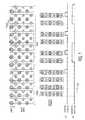
- FIGURE 1is a pictorial representation and waveform diagram of a sequence of video signal input frames and reconstituted frames, which representation is useful in describing the invention.
- FIGURE 2is a pictorial representation and flag signal diagram of a sequence of video signal output frames provided by a decoder apparatus, and a pictorial representation of resequenced fields of video signal for providing an interlaced video signal, which representations are useful in describing the invention.
- FIGURE 3is a block diagram of apparatus for excising redundant fields of video signal and generating flag signals.
- FIGURE 4is a block diagram of a resequencer which may be utilized in the FIGURE 3 apparatus.
- FIGURE 5is a flow chart detailing the functional operation of the resequencer of FIGURES 3 and 4.
- FIGURE 6is a block diagram of decoder apparatus for generating substitute video fields for excised redundant video fields.
- Each column of circlesrepresents a field of video signal, with each circle in a field representing a horizontal line.
- the respective boxes encompassing two such fieldsrepresent frames of interlaced video signal generated by, for example, a video camera.
- the portion of the row of boxes designated "film”,constitutes video signal developed by, for example, a telecine wherein one of every four occurring fields is reproduced in the signal stream.
- the repeated fieldsare incorporated in the boxes encompassing three fields. For example, in the box including the fields L, M and N, field N is a repeat of field L.
- the row of boxes designated output framesrepresents resequenced frames of video signal after redundant fields have been excised.
- the "video" framescontain moving images, and therefor only "film” frames will have redundant fields of information, whether or not the "film” sequences contain moving images.
- the resequenced fieldsare arranged in non-interlaced frames for application to, for example, an MPEG encoder. It can be seen that for every five fields of input signal designated"film" frames, the output frames include only four fields, effecting a 20% data reduction.
- the input video signalcould just as well represent still "video", in which case successive even fields will be identical except for noise contributions, and successive odd fields will be identical except for noise contributions.
- the redundant fieldsmay occur randomly or bunched together. If the redundant fields occur randomly, the present system will excise the redundant fields as they occur. If, on the other hand, still fields occur in relatively large bursts, only m of every n redundant fields will be excised, where m and n are integers with n greater than m. This constraint is imposed to preclude the system rate buffer from underflowing. Note, representative values for n and m are 3 and 1 or 5 and 1, etc.
- a signal DTindicates the ones of the resequenced frames that include a field corresponding to a field which has been excised.
- a representation of the signal DTwill be included in the transmitted encoded signal to inform the receiver that one of the fields in the associated frame should be displayed twice.
- a second signal DFindicates which field in every frame is to be displayed first by an interlace display system.
- a representation of the signal DFis also included in the transmitted encoded signal. It will be noted from the input and output video fields/frames that even fields nominally occur in time after odd fields. That is an interlace frame includes an odd field interlaced with a subsequently scanned even field. However when video data is excised on a field basis, reconstructed output frames may include an odd field with a prior occurring even field.
- FIGURE 2the row of boxes designated input frames represents the output frames of FIGURE 1 after having been decoded in an appropriate receiver.
- the corresponding signal DT and DFrepresented as two-bit binary words.
- the leftmost and rightmost bitsrepresent the signals DT and DF respectively.
- a one in the left bit positionindicates that the associated frame includes a redundant field.
- a one in the right bit positionindicates that the even field of the associated frame is to be displayed first and a zero in the right position indicates that the odd field of the associated frame is to be displayed first.
- Output Fieldsrepresents the sequence that the fields comprising the input frames should be displayed.
- FIGURE 3illustrates apparatus for detecting redundant fields, excising redundant fields and reconstructing frames of video signal from the remaining fields.
- Video signalis applied from a source 10 to a first buffer memory (Bn) 12 and a subtracter 16.
- An output from the buffer memory 12is coupled to a second buffer memory (Bn-1) 14.
- the output of the second buffer memoryis coupled to the second input of the subtracter 16.
- the first and second buffer memorieseach delay signal by one field period, hence the two video signals applied to the subtracter 16 correspond to like spatial positions of like field types separated by one frame interval. If two fields of video signal separated by a frame are identical (excluding noise) the differences provided by the subtracter 16 over respective field periods will be zero (assuming the video signal represents luminance only).
- the differences developed by the subtracter 16are applied to a coring circuit 17, which eliminates signal differences less than a predetermined value in order to minimize the effects of signal noise in the video signal differences.
- the cored difference valuesare applied to an accumulator 18 wherein the absolute values of the differences are accumulated (summed) over respective field intervals.
- the summed valuesare applied to a threshold detector 20 wherein they are compared to a threshold value, and if the sum of differences for a respective field is less than the threshold value, the field stored in buffer memory 12 is considered redundant with the lastmost previous field of the same type, that is the last field read out of buffer memory 14. If the sum is greater than the threshold value, the field currently stored in buffer memory 12 in considered non-redundant.
- Video data from the buffer memories 12 and 14are applied to a resequencer 21, and video data from the source 10 are applied to the odd/even field type detector 11.
- the resequencer 21responsive to field type data from the detector 11, and data from the threshold detector 20, excises and reformats the fields of data from the source 10.
- the resequenced video signal datais applied to a compression apparatus 23 which may include a motion compensated predictive encoder associated with a Discrete Cosine Transform encoder, and statistical and run length encoders.
- Compressed video signal provided by the compression apparatus 23is applied to a data formatter 24.
- the data formatterformats the compressed data with ancillary data for synchronization and/or error detection/correction.
- the compressed video signalis to be transmitted over a medium other than copper wire, for example, it will be necessary to provide the compressed video signal with further noise protection.
- the compressed data from the data formatter 24is applied to a transport processor 26 which adds signal redundancy.
- This redundancyis specific to certain types of data critical to signal decoding.
- the transport processor 26forms packets of data having a payload of a predetermined number of compressed video bits, and flexible headers including data which identifies the spatial location within respective images from which the payload data was derived.
- the formatter 24 and the compression apparatus 23operate under the control of a compression controller 22.
- the controller 22receives video data and display data (DF) from the resequencer 21, and data DT from the threshold detector 20.
- the controller 22will nominally operate as a state machine to condition the compressor to provide data in a predetermined sequence, and to condition the formatter 24 to layer the output data in a predetermined hierarchy, e.g. according to the MPEG signal protocol. If in fact the controller and formatter are programmed to provide MPEG formatted data, the aforementioned flag signals DT/DF will not be introduced in the data stream by the formatter 24.
- the signals DT/DFwill be provided to the transport processor 26 with the associated frames of compressed video data.
- the signals DT/DFmay thereafter be incorporated in respective transport packet headers associated with transport packets conveying payloads which include Frame Header information.
- the encoder 25is not an MPEG encoder, but perhaps a modified MPEG+ encoder, provision may be made to incorporate the signals DT/DF within the frame headers of the modified MPEG compressed data.
- the controller 22 and formatter 24will be prearranged to incorporate the signals DT/DF directly into the compressed video data stream. It will be appreciated by those skilled in video signal compression techniques, and armed with the foregoing disclosure, that varied other methods may be implemented for conveying the respective flag signals associated with fields/frames conveying redundant data.
- FIGURE 4illustrates exemplary apparatus for the resequencer 21 of FIGURE 3.
- the resequencer 21 of FIGURE 4forms frames from fields of video data. That is, it interleaves horizontal lines of even fields with horizontal lines of odd fields to form a frame from two fields. The interleaving is performed by the register pairs 30, 31 and 32, 33. Buffer memories 12 and 14 will always be conditioned to contain the two fields to be combined into respective frames. The field memories 12 and 14 will be read out concurrently, a line at a time. Respective lines read out of memory 12 are written to a serial-input-parallel-output register 30, having parallel output connections coupled to parallel input connections of a parallel-input-serial-output register 31.
- register 30After a respective line is written to register 30, it is loaded into register 31. Thereafter the line is serially read out of register 31. Similarly respective lines read from memory 14 are written to register 32, transferred to register 34, and then serially read out of register 34.
- the output signals provided by registers 31 and 33are coupled to respective input connections of a multiplexer 34.
- the multiplexer 34is conditioned by the resequence controller 35 to couple even field lines in even field line positions and odd field lines in odd field line positions within each composed frame.
- datais read from the field memories 12 and 14 at a predetermined sample rate a line at a time. Thereafter the registers 31 and 32 are clocked mutually exclusively, under control of the controller 35, at twice this sample rate such that the signal output from the multiplexer consists of a line of video signal from register 31 (33) followed by a line of video signal from register 33 (31).
- the field detector 11determines whether the fields are odd or even and conveys such field type information to the controller 35. Controller 35 therefore knows which of buffer memories 12 and 14 contain the odd and the even field, and thus may appropriately switch the multiplexer 34.
- the controller 35is also supplied with data from the threshold detector and is arranged to generate the signal DT/DF.
- FIGURE 5is a flow chart of the operation of the FIGURE 4 resequencer, which operates as follows. At system startup two consecutive fields are loaded [100] into the buffer memories 12 and 14 and an index n is set to 2. The resequencer then fetches [101] the field type (even or odd) of the field loaded in memory 12. The field type is examined [102], and if the next field should be an even (odd) field the system branches to path 103, 104, 105 (107, 108, 109).
- the index nis incremented by one, and loading of the next field into memory 12 is initiated [103]. If even then the field currently residing in memories 12 (Bn) and 14 (Bn-1) are odd and even respectively.
- the current frameis built [104] from the fields currently in memories Bn and Bn-1, with lines of video signal from memory Bn as odd lines and lines of video signal from memory Bn-1 as even lines.
- the odd and even fields in memories 12 and 14are in reverse time order and thus the signal display first (DF) is set to a logic one value [105].
- the index nis incremented by one, and loading of the next field into memory 12 is initiated [107]. If odd then the field currently residing in memories 12 (Bn) and 14 (Bn-1) are even and odd respectively.
- the current frameis built [108] from the fields currently in memories Bn and Bn-1, with lines of video signal from memory Bn as even lines and lines of video signal from memory Bn-1 as odd lines.
- the even and odd fields in memories 12 and 14are in normal order and thus the signal display first (DF) is set to a logic zero value [109].
- the signal DT from the threshold detectoris loaded [110] and examined [111] for the current field. If the signal DT is low indicating no field redundancy, the next field is loaded [115] into memory so the memories 12 and 14 contain a new frame of data. The system then returns to step [101].
- variable last_dropis examined [112].
- the variable LDkeeps track of the most recently dropped field.
- the variable LDis subtracted from the index n, and the difference is compared to a further predetermined value drop frequency FD.
- the value FDdetermines the number of fields that are permitted to be dropped per sequence of fields. The lowest valid value of FD is 3 permitting one in three fields to be dropped. An FD value of 5 will permit no more than one in five fields to be dropped.
- DTis set to zero [113] and the system branches to step 115. In this instance the system precludes the dropping of a field even though it is redundant.
- LDis set to n [114] and the next two fields are loaded [116] into the memories 12 and 14. This has the effect of dropping the field currently residing in the memory 14. The system then branches back to step [101].
- FIGURE 6illustrates an exemplary embodiment of a receiver prepared to utilize the flag data DT/DF to reconstruct video data in which redundant fields have been excised.
- Compressed video data from a transmission pathfor example a tuner is applied to a transport processor 60.
- the transport processorreceives the transport packets of compressed video and synchronizing information etc., separates the compressed video signal from the transport packet headers, and applies the compressed video signal to an appropriate decoder/decompresser. If the redundant field flag data DT/DF is contained in the packet transport headers, this flag data is separated and applied to the system controller 64, with any other ancillary data needed by the system controller 64. If the flag data DT/DF is contained in the compressed video signal per se', it is separated by the decoder/decompresser 61, and applied to the system controller 64. The system controller ultimately directs the signal DT/DF to a memory controller 66.
- Compressed video signalis decompressed by the decoder 61 and loaded into a display memory 62. Nominally the display memory 62 will contain a frame of decompressed data.
- the decompressed datais coupled from the display memory to an output display device (or to a recording device etc) via a multiplexer 63. When no field redundancy is indicated, data is coupled directly from the memory 62 to the output device.
- the output of the display memoryis also coupled to an additional field memory 65, and the output of the field memory 65 is coupled to a second input of the multiplexer 63.
- the display memory 62, field memory 65 and multiplexer 63are controlled by a memory controller 66.
- the memory controller 66is conditioned by the system controller 64, including signals DT/DF, to provide video data from the respective memories for display. If no field redundancy is indicated by the signals DT/DF, decompressed odd and even fields are respectively loaded into the display memory in odd and even field positions responsive to the signal DF. The odd and even fields are then consecutively read from the memory 62 in interlace fashion.
- a field associated with redundant informationis indicated by the signal DT/DF, when such field is read out to the display device it is concurrently captured in the field memory 65. Thereafter the field of video signal in the field memory 65 is coupled to the display device by the multiplexer 63 in the appropriate field position.
- the multiplexer 63it may not be necessary to include an extra field memory 65 and multiplexer 63, for field repeats, and the repeating of fields of video signal may be performed directly from the display memory 62. The latter arrangement reduces the amount of necessary hardware, but increases timing constraints on both the display memory and the decompresser 61.
Landscapes
- Multimedia (AREA)
- Signal Processing (AREA)
- Engineering & Computer Science (AREA)
- Television Systems (AREA)
- Compression Or Coding Systems Of Tv Signals (AREA)
- Details Of Television Scanning (AREA)
- Reduction Or Emphasis Of Bandwidth Of Signals (AREA)
- Color Television Systems (AREA)
- Measuring And Recording Apparatus For Diagnosis (AREA)
- Compression, Expansion, Code Conversion, And Decoders (AREA)
- Measurement And Recording Of Electrical Phenomena And Electrical Characteristics Of The Living Body (AREA)
- Image Processing (AREA)
- Magnetic Resonance Imaging Apparatus (AREA)
- Television Signal Processing For Recording (AREA)
- Two-Way Televisions, Distribution Of Moving Picture Or The Like (AREA)
- Processing Of Solid Wastes (AREA)
- Apparatus For Radiation Diagnosis (AREA)
Abstract
Description
Claims (6)
- Video signal compression apparatus comprising:a source (10) of video signal including even and oddfields;means (21) for combining said even and odd fields intooutput frames of video signal;a source (20, 21) of codewords DT/DF indicative ofwhether or not a field has been excised and indicative ofthe temporal order of fields of respective output frames;means (25) for compressing said output frames; andmeans (26) for combining compressed frames of video signaland said codewords DT/DF corresponding to respectivecompressed frames, for transmission.
- The video signal compression apparatus set forth in claim1, including:circuitry (12, 14, 16) for comparing corresponding fields of successive framesand excising one of said fields if said compared fields are substantially similar;andsaid combining means (21) combining the remaining fieldsinto frames.
- The video signal compression apparatus set forth in claim2, wherein said circuitry for comparing includesmeans (12, 14, 16) for comparing successive even fieldsand comparing successive odd fields and if respectiveones of the successive even or successive odd fields aresubstantially similar, excising one of a pair of suchsubstantially similar fields.
- The video signal compression apparatus set forth in claim2, further including:means (20), for generating first flag data indicating respectivegenerated output frames which contain a remaining field corresponding to a field which has been excised;andmeans (21) for generating second flag data indicating thetemporal order of the remaining fields in respective outputframes.
- Apparatus for receiving a compressed video signal includinginformation DT/DF indicative of the order of displayof decompressed fields, said apparatus comprising:means for receiving said compressed video signal;means (60) responsive to said received compressed videosignal for separating said information DT/DF;means (61, 62, 66) responsive to said received compressedvideo signal for decompressing said compressed video signalto provide output frames of video signal; andmeans (63, 65, 66) responsive to said information DT/DFfor sequencing said decompressed fields in a predeterminedorder.
- The apparatus set forth in claim 5, wherein said meansresponsive to said information DT/DF further includesmeans (65, 66) responsive to said information DT/DF forrepeating ones of decompressed fields.
Applications Claiming Priority (3)
| Application Number | Priority Date | Filing Date | Title |
|---|---|---|---|
| US08/004,753US5491516A (en) | 1993-01-14 | 1993-01-14 | Field elimination apparatus for a video compression/decompression system |
| US4753 | 1993-01-14 | ||
| PCT/US1994/000313WO1994016526A1 (en) | 1993-01-14 | 1994-01-10 | Field elimination apparatus for a video compression/decompression system |
Publications (2)
| Publication Number | Publication Date |
|---|---|
| EP0679316A1 EP0679316A1 (en) | 1995-11-02 |
| EP0679316B1true EP0679316B1 (en) | 1998-06-03 |
Family
ID=21712357
Family Applications (1)
| Application Number | Title | Priority Date | Filing Date |
|---|---|---|---|
| EP94906576AExpired - LifetimeEP0679316B1 (en) | 1993-01-14 | 1994-01-10 | Field elimination apparatus for a video compression/decompression system |
Country Status (17)
| Country | Link |
|---|---|
| US (3) | US5491516A (en) |
| EP (1) | EP0679316B1 (en) |
| JP (2) | JP3510628B2 (en) |
| KR (1) | KR100282981B1 (en) |
| CN (1) | CN1080516C (en) |
| AT (1) | ATE167015T1 (en) |
| BR (1) | BR9405710A (en) |
| CA (1) | CA2153886C (en) |
| DE (1) | DE69410781T2 (en) |
| ES (1) | ES2117252T3 (en) |
| FI (1) | FI113929B (en) |
| MY (1) | MY109889A (en) |
| RU (1) | RU2115258C1 (en) |
| SG (2) | SG110033A1 (en) |
| TR (1) | TR27398A (en) |
| TW (1) | TW225080B (en) |
| WO (1) | WO1994016526A1 (en) |
Families Citing this family (88)
| Publication number | Priority date | Publication date | Assignee | Title |
|---|---|---|---|---|
| AU4662493A (en)* | 1992-07-01 | 1994-01-31 | Avid Technology, Inc. | Electronic film editing system using both film and videotape format |
| JP3443880B2 (en)* | 1992-09-18 | 2003-09-08 | ソニー株式会社 | Video signal encoding method and decoding method |
| JP3531594B2 (en) | 1992-09-18 | 2004-05-31 | ソニー株式会社 | Video signal decoding method and apparatus |
| JP3531186B2 (en) | 1992-09-18 | 2004-05-24 | ソニー株式会社 | Video signal encoding method and apparatus |
| US5828786A (en)* | 1993-12-02 | 1998-10-27 | General Instrument Corporation | Analyzer and methods for detecting and processing video data types in a video data stream |
| JP2947400B2 (en)* | 1994-05-31 | 1999-09-13 | 日本ビクター株式会社 | Frame frequency converter |
| JP3629728B2 (en)* | 1994-08-31 | 2005-03-16 | ソニー株式会社 | Moving picture signal encoding method, moving picture signal encoding apparatus, and moving picture signal recording medium |
| US5734419A (en)* | 1994-10-21 | 1998-03-31 | Lucent Technologies Inc. | Method of encoder control |
| US5691771A (en)* | 1994-12-29 | 1997-11-25 | Sony Corporation | Processing of redundant fields in a moving picture to achieve synchronized system operation |
| US6148035A (en)* | 1994-12-29 | 2000-11-14 | Sony Corporation | Processing of redundant fields in a moving picture to achieve synchronized system operation |
| US5844618A (en)* | 1995-02-15 | 1998-12-01 | Matsushita Electric Industrial Co., Ltd. | Method and apparatus for telecine image conversion |
| US5734677A (en)* | 1995-03-15 | 1998-03-31 | The Chinese University Of Hong Kong | Method for compression of loss-tolerant video image data from multiple sources |
| US5920572A (en)* | 1995-06-30 | 1999-07-06 | Divicom Inc. | Transport stream decoder/demultiplexer for hierarchically organized audio-video streams |
| US6058140A (en)* | 1995-09-08 | 2000-05-02 | Zapex Technologies, Inc. | Method and apparatus for inverse 3:2 pulldown detection using motion estimation information |
| US5835493A (en)* | 1996-01-02 | 1998-11-10 | Divicom, Inc. | MPEG transport stream remultiplexer |
| US6968003B1 (en)* | 1996-01-29 | 2005-11-22 | International Business Machines Corporation | Speed-memory tradeoff for MPEG decoders |
| US5852473A (en)* | 1996-02-20 | 1998-12-22 | Tektronix, Inc. | 3-2 pulldown detector |
| JP2848326B2 (en)* | 1996-03-28 | 1999-01-20 | 日本電気株式会社 | MPEG encoded image decoding device |
| US5903261A (en)* | 1996-06-20 | 1999-05-11 | Data Translation, Inc. | Computer based video system |
| US6222589B1 (en) | 1996-08-08 | 2001-04-24 | Yves C. Faroudja | Displaying video on high-resolution computer-type monitors substantially without motion discontinuities |
| US6341144B1 (en)* | 1996-09-20 | 2002-01-22 | At&T Corp. | Video coder providing implicit coefficient prediction and scan adaptation for image coding and intra coding of video |
| US5966166A (en)* | 1996-11-07 | 1999-10-12 | At&T Corp | System and method for compressing video data for video conferencing at a reduced frame rate |
| KR100436649B1 (en)* | 1996-12-20 | 2004-09-08 | 소니 일렉트로닉스 인코포레이티드 | Method and apparuatus for changing phase of video program material taken from 24 frame per second film |
| US6118491A (en)* | 1997-02-20 | 2000-09-12 | Lsi Logic Corporation | System and method for enforcing interlaced field synchronization in the presence of broken alternation in an MPEG video datastream |
| US6269195B1 (en) | 1997-04-04 | 2001-07-31 | Avid Technology, Inc. | Apparatus and methods for selectively feathering a composite image |
| US6128001A (en)* | 1997-04-04 | 2000-10-03 | Avid Technology, Inc. | Methods and apparatus for changing a color of an image |
| US5929942A (en)* | 1997-04-04 | 1999-07-27 | Avid Technology, Inc. | Computer system and computer implemented process for editing video fields |
| JP3232052B2 (en) | 1997-10-31 | 2001-11-26 | 松下電器産業株式会社 | Image decoding method |
| US6246701B1 (en) | 1998-01-14 | 2001-06-12 | Skystream Corporation | Reference time clock locking in a remultiplexer for video program bearing transport streams |
| US6351471B1 (en) | 1998-01-14 | 2002-02-26 | Skystream Networks Inc. | Brandwidth optimization of video program bearing transport streams |
| US6351474B1 (en) | 1998-01-14 | 2002-02-26 | Skystream Networks Inc. | Network distributed remultiplexer for video program bearing transport streams |
| US6195368B1 (en) | 1998-01-14 | 2001-02-27 | Skystream Corporation | Re-timing of video program bearing streams transmitted by an asynchronous communication link |
| US6292490B1 (en) | 1998-01-14 | 2001-09-18 | Skystream Corporation | Receipts and dispatch timing of transport packets in a video program bearing stream remultiplexer |
| US6351557B1 (en) | 1998-04-03 | 2002-02-26 | Avid Technology, Inc. | Method and apparatus for color manipulation |
| US6392710B1 (en) | 1998-04-03 | 2002-05-21 | Avid Technology, Inc. | Graphical user interface for field-based definition of special effects in a video editing system |
| US6298090B1 (en) | 1998-06-04 | 2001-10-02 | U.S. Philips Corporation | System for detecting redundant images in a video sequence by comparing two predetermined threshold values |
| US6148317A (en)* | 1998-08-14 | 2000-11-14 | Qualcomm Incorporated | Method and apparatus for compressing signals in a fixed point format without introducing a bias |
| US6563953B2 (en)* | 1998-11-30 | 2003-05-13 | Microsoft Corporation | Predictive image compression using a single variable length code for both the luminance and chrominance blocks for each macroblock |
| DE69806976T2 (en) | 1998-12-02 | 2003-03-27 | Stmicroelectronics Asia Pacific Pte Ltd., Singapur/Singapore | DETERMINATION OF SKIP / PROGRESSIVE FASHION AND OF REDUNDANT HALF-IMAGES FOR ENCODERS |
| TR200002630T1 (en)* | 1999-01-13 | 2000-12-21 | Koninklijke Philips Electronics N.V. | Adding complementary data to an encoded signal |
| US6417891B1 (en) | 1999-04-16 | 2002-07-09 | Avid Technology, Inc. | Color modification on a digital nonlinear editing system |
| US6847373B1 (en)* | 1999-04-16 | 2005-01-25 | Avid Technology, Inc. | Natural color matching in a video editing system |
| US6552731B1 (en) | 1999-04-16 | 2003-04-22 | Avid Technology, Inc. | Multi-tone representation of a digital image on a digital nonlinear editing system |
| US6571255B1 (en) | 1999-04-16 | 2003-05-27 | Robert Gonsalves | Modification of media with common attributes on a digital nonlinear editing system |
| CN1319309A (en)* | 1999-08-03 | 2001-10-24 | 皇家菲利浦电子有限公司 | Method and device for encoding sequences of frames including either video-type or film-type images |
| JP4331835B2 (en)* | 1999-09-22 | 2009-09-16 | パナソニック株式会社 | Image data transmission method |
| CA2394352C (en) | 1999-12-14 | 2008-07-15 | Scientific-Atlanta, Inc. | System and method for adaptive decoding of a video signal with coordinated resource allocation |
| GB0004862D0 (en)* | 2000-02-29 | 2000-04-19 | Blip X Limited | Video compression |
| KR20020026153A (en)* | 2000-02-29 | 2002-04-06 | 요트.게.아. 롤페즈 | Film source video detection and encoding |
| US6563550B1 (en)* | 2000-03-06 | 2003-05-13 | Teranex, Inc. | Detection of progressive frames in a video field sequence |
| US6477271B1 (en) | 2000-04-07 | 2002-11-05 | Avid Technology, Inc. | Secondary color modification of a digital image |
| US6928187B2 (en)* | 2000-04-07 | 2005-08-09 | Avid Technology, Inc. | Secondary color modification of a digital image |
| US6756996B2 (en)* | 2000-12-19 | 2004-06-29 | Intel Corporation | Obtaining a high refresh rate display using a low bandwidth digital interface |
| BR0109448A (en)* | 2001-01-23 | 2003-06-03 | Koninkl Philips Electronics Nv | Process and arrangement for embedding a watermark in an information signal |
| US8880709B2 (en)* | 2001-09-12 | 2014-11-04 | Ericsson Television Inc. | Method and system for scheduled streaming of best effort data |
| AU2002351389A1 (en)* | 2001-12-17 | 2003-06-30 | Microsoft Corporation | Skip macroblock coding |
| US7274857B2 (en)* | 2001-12-31 | 2007-09-25 | Scientific-Atlanta, Inc. | Trick modes for compressed video streams |
| PE20040139A1 (en)* | 2002-06-04 | 2004-04-15 | Qualcomm Inc | METHOD AND APPARATUS TO PLAY MULTIMEDIA CONTENT ON A PORTABLE DEVICE THAT HAS A BUILT-IN PROCESSOR |
| US7433519B2 (en)* | 2003-04-04 | 2008-10-07 | Avid Technology, Inc. | Bitstream format for compressed image data |
| US7403561B2 (en)* | 2003-04-04 | 2008-07-22 | Avid Technology, Inc. | Fixed bit rate, intraframe compression and decompression of video |
| US7499495B2 (en)* | 2003-07-18 | 2009-03-03 | Microsoft Corporation | Extended range motion vectors |
| US20050013498A1 (en) | 2003-07-18 | 2005-01-20 | Microsoft Corporation | Coding of motion vector information |
| US7609763B2 (en) | 2003-07-18 | 2009-10-27 | Microsoft Corporation | Advanced bi-directional predictive coding of video frames |
| US7693222B2 (en)* | 2003-08-13 | 2010-04-06 | Ericsson Television Inc. | Method and system for re-multiplexing of content-modified MPEG-2 transport streams using PCR interpolation |
| US7961786B2 (en)* | 2003-09-07 | 2011-06-14 | Microsoft Corporation | Signaling field type information |
| US7606308B2 (en)* | 2003-09-07 | 2009-10-20 | Microsoft Corporation | Signaling macroblock mode information for macroblocks of interlaced forward-predicted fields |
| US7599438B2 (en) | 2003-09-07 | 2009-10-06 | Microsoft Corporation | Motion vector block pattern coding and decoding |
| US7567617B2 (en)* | 2003-09-07 | 2009-07-28 | Microsoft Corporation | Predicting motion vectors for fields of forward-predicted interlaced video frames |
| US8107531B2 (en)* | 2003-09-07 | 2012-01-31 | Microsoft Corporation | Signaling and repeat padding for skip frames |
| US8064520B2 (en) | 2003-09-07 | 2011-11-22 | Microsoft Corporation | Advanced bi-directional predictive coding of interlaced video |
| US7620106B2 (en)* | 2003-09-07 | 2009-11-17 | Microsoft Corporation | Joint coding and decoding of a reference field selection and differential motion vector information |
| US7623574B2 (en)* | 2003-09-07 | 2009-11-24 | Microsoft Corporation | Selecting between dominant and non-dominant motion vector predictor polarities |
| US7616692B2 (en)* | 2003-09-07 | 2009-11-10 | Microsoft Corporation | Hybrid motion vector prediction for interlaced forward-predicted fields |
| US7724827B2 (en)* | 2003-09-07 | 2010-05-25 | Microsoft Corporation | Multi-layer run level encoding and decoding |
| US7966642B2 (en)* | 2003-09-15 | 2011-06-21 | Nair Ajith N | Resource-adaptive management of video storage |
| US20050120340A1 (en)* | 2003-12-01 | 2005-06-02 | Skazinski Joseph G. | Apparatus, system, and method for automated generation of embedded systems software |
| WO2005055606A1 (en)* | 2003-12-01 | 2005-06-16 | Samsung Electronics Co., Ltd. | Method and apparatus for scalable video encoding and decoding |
| JP4931034B2 (en)* | 2004-06-10 | 2012-05-16 | 株式会社ソニー・コンピュータエンタテインメント | Decoding device, decoding method, program, and program recording medium |
| US8600217B2 (en)* | 2004-07-14 | 2013-12-03 | Arturo A. Rodriguez | System and method for improving quality of displayed picture during trick modes |
| US9077960B2 (en)* | 2005-08-12 | 2015-07-07 | Microsoft Corporation | Non-zero coefficient block pattern coding |
| JP2007053554A (en)* | 2005-08-17 | 2007-03-01 | Sony Corp | Device and method for encoding, device and method for decoding, and program |
| CN101054750B (en)* | 2007-05-15 | 2010-09-08 | 江苏万工科技集团有限公司 | Electronic jacquard machine control system with data checking and correction function and control method thereof |
| US20090033791A1 (en)* | 2007-07-31 | 2009-02-05 | Scientific-Atlanta, Inc. | Video processing systems and methods |
| US8300696B2 (en)* | 2008-07-25 | 2012-10-30 | Cisco Technology, Inc. | Transcoding for systems operating under plural video coding specifications |
| US9148295B2 (en)* | 2010-02-09 | 2015-09-29 | Broadcom Corporation | Cable set-top box with integrated cable tuner and MOCA support |
| CN103313090B (en)* | 2012-03-16 | 2017-05-03 | 腾讯科技(深圳)有限公司 | Method and system for off-line downloading video files |
| US9998750B2 (en) | 2013-03-15 | 2018-06-12 | Cisco Technology, Inc. | Systems and methods for guided conversion of video from a first to a second compression format |
| CN110312095B (en)* | 2018-03-20 | 2021-10-08 | 瑞昱半导体股份有限公司 | Image processing device and image processing method |
Family Cites Families (13)
| Publication number | Priority date | Publication date | Assignee | Title |
|---|---|---|---|---|
| US3184542A (en)* | 1961-03-15 | 1965-05-18 | David S Horsley | Video recording and reproduction with reduced redundancy |
| GB2129651B (en)* | 1982-10-28 | 1986-08-06 | Quantel Ltd | Video processors |
| NL8801347A (en)* | 1988-05-26 | 1989-12-18 | Philips Nv | METHOD AND APPARATUS FOR MOTION DETECTION IN AN INTERLININED TELEVISION IMAGE OBTAINED AFTER A FILM-TELEVISION CONVERSION. |
| US4998287A (en)* | 1988-10-14 | 1991-03-05 | General Instrument Corporation | Determination of sequential positions of video fields derived from film |
| US4982280A (en)* | 1989-07-18 | 1991-01-01 | Yves C. Faroudja | Motion sequence pattern detector for video |
| DE69028847T2 (en)* | 1989-10-20 | 1997-04-03 | Snell & Wilcox Ltd | DIGITAL TELEVISION CONVERSION |
| US4998167A (en)* | 1989-11-14 | 1991-03-05 | Jaqua Douglas A | High resolution translation of images |
| US5187575A (en)* | 1989-12-29 | 1993-02-16 | Massachusetts Institute Of Technology | Source adaptive television system |
| GB9001079D0 (en)* | 1990-01-17 | 1990-03-14 | Avesco Plc | Standards conversion |
| US5174641A (en)* | 1990-07-25 | 1992-12-29 | Massachusetts Institute Of Technology | Video encoding method for television applications |
| US5093720A (en)* | 1990-08-20 | 1992-03-03 | General Instrument Corporation | Motion compensation for interlaced digital television signals |
| US5168356A (en)* | 1991-02-27 | 1992-12-01 | General Electric Company | Apparatus for segmenting encoded video signal for transmission |
| US5444491A (en)* | 1993-02-26 | 1995-08-22 | Massachusetts Institute Of Technology | Television system with multiple transmission formats |
- 1993
- 1993-01-14USUS08/004,753patent/US5491516A/ennot_activeExpired - Lifetime
- 1993-10-05TWTW082108202Apatent/TW225080B/ennot_activeIP Right Cessation
- 1993-12-30MYMYPI93002876Apatent/MY109889A/enunknown
- 1994
- 1994-01-10KRKR1019950702901Apatent/KR100282981B1/ennot_activeExpired - Lifetime
- 1994-01-10CACA002153886Apatent/CA2153886C/ennot_activeExpired - Lifetime
- 1994-01-10SGSG200301641Apatent/SG110033A1/enunknown
- 1994-01-10JPJP51626894Apatent/JP3510628B2/ennot_activeExpired - Lifetime
- 1994-01-10CNCN94191176Apatent/CN1080516C/ennot_activeExpired - Lifetime
- 1994-01-10WOPCT/US1994/000313patent/WO1994016526A1/enactiveIP Right Grant
- 1994-01-10ATAT94906576Tpatent/ATE167015T1/enactive
- 1994-01-10ESES94906576Tpatent/ES2117252T3/ennot_activeExpired - Lifetime
- 1994-01-10RURU95116653Apatent/RU2115258C1/enactive
- 1994-01-10DEDE69410781Tpatent/DE69410781T2/ennot_activeExpired - Lifetime
- 1994-01-10EPEP94906576Apatent/EP0679316B1/ennot_activeExpired - Lifetime
- 1994-01-10BRBR9405710Apatent/BR9405710A/ennot_activeIP Right Cessation
- 1994-01-10SGSG9602473Apatent/SG94680A1/enunknown
- 1994-01-12TRTR00029/94Apatent/TR27398A/enunknown
- 1994-10-18USUS08/324,558patent/US5426464A/ennot_activeExpired - Lifetime
- 1995
- 1995-03-20USUS08/407,735patent/US5600376A/ennot_activeExpired - Lifetime
- 1995-07-13FIFI953429Apatent/FI113929B/ennot_activeIP Right Cessation
- 2003
- 2003-10-08JPJP2003348928Apatent/JP4002549B2/ennot_activeExpired - Lifetime
Also Published As
| Publication number | Publication date |
|---|---|
| MY109889A (en) | 1997-09-30 |
| KR100282981B1 (en) | 2001-03-02 |
| TR27398A (en) | 1995-02-28 |
| FI953429A0 (en) | 1995-07-13 |
| CA2153886C (en) | 2003-08-05 |
| KR960700610A (en) | 1996-01-20 |
| FI953429A7 (en) | 1995-08-23 |
| BR9405710A (en) | 1996-08-06 |
| EP0679316A1 (en) | 1995-11-02 |
| US5491516A (en) | 1996-02-13 |
| CN1080516C (en) | 2002-03-06 |
| WO1994016526A1 (en) | 1994-07-21 |
| CA2153886A1 (en) | 1994-07-21 |
| JPH08507182A (en) | 1996-07-30 |
| JP2004088800A (en) | 2004-03-18 |
| US5426464A (en) | 1995-06-20 |
| DE69410781D1 (en) | 1998-07-09 |
| ATE167015T1 (en) | 1998-06-15 |
| CN1117780A (en) | 1996-02-28 |
| JP4002549B2 (en) | 2007-11-07 |
| SG94680A1 (en) | 2003-03-18 |
| ES2117252T3 (en) | 1998-08-01 |
| SG110033A1 (en) | 2005-04-28 |
| JP3510628B2 (en) | 2004-03-29 |
| US5600376A (en) | 1997-02-04 |
| TW225080B (en) | 1994-06-11 |
| DE69410781T2 (en) | 1998-10-15 |
| FI113929B (en) | 2004-06-30 |
| RU2115258C1 (en) | 1998-07-10 |
Similar Documents
| Publication | Publication Date | Title |
|---|---|---|
| EP0679316B1 (en) | Field elimination apparatus for a video compression/decompression system | |
| JP3365771B2 (en) | Video signal compression device | |
| CA2109520C (en) | Video signal decompression apparatus for independently compressed even and odd field data | |
| US5455629A (en) | Apparatus for concealing errors in a digital video processing system | |
| US5442400A (en) | Error concealment apparatus for MPEG-like video data | |
| KR100341055B1 (en) | Syntax Analyzer for Video Compression Processor | |
| US6393152B2 (en) | Hierarchical image decoding apparatus and multiplexing method | |
| EP0646306B1 (en) | Apparatus for arranging compressed video data for transmission over a noisy communication channel | |
| USRE41569E1 (en) | Method of processing variable size blocks of data by storing numbers representing size of data blocks in a fifo | |
| EP0611512B1 (en) | Apparatus for concealing errors in a digital video processing system | |
| US5504823A (en) | Image data partitioning circuit for parallel image decoding system | |
| JP3171776B2 (en) | Compression method and context modeler | |
| JPH06224861A (en) | Data separation processor | |
| EP0642273B1 (en) | Image processing apparatus concealing errors in motion image data | |
| KR0185927B1 (en) | Image decoding apparatus and method for converting frame rate of input bit stream | |
| WO1993020652A1 (en) | Method and apparatus for compressing and decompressing a sequence of digital video images using sync frames | |
| GB2326300A (en) | Video data compression system | |
| JP4355914B2 (en) | Multi-view image transmission system and method, multi-view image compression device and method, multi-view image decompression device and method, and program | |
| CA2360556C (en) | Error concealment apparatus for a compressed video signal processing system | |
| JPH11239326A (en) | Multiplex synchronization method and its system |
Legal Events
| Date | Code | Title | Description |
|---|---|---|---|
| PUAI | Public reference made under article 153(3) epc to a published international application that has entered the european phase | Free format text:ORIGINAL CODE: 0009012 | |
| 17P | Request for examination filed | Effective date:19950712 | |
| AK | Designated contracting states | Kind code of ref document:A1 Designated state(s):AT DE ES FR GB IT PT SE | |
| 17Q | First examination report despatched | Effective date:19960613 | |
| GRAG | Despatch of communication of intention to grant | Free format text:ORIGINAL CODE: EPIDOS AGRA | |
| GRAG | Despatch of communication of intention to grant | Free format text:ORIGINAL CODE: EPIDOS AGRA | |
| GRAG | Despatch of communication of intention to grant | Free format text:ORIGINAL CODE: EPIDOS AGRA | |
| GRAG | Despatch of communication of intention to grant | Free format text:ORIGINAL CODE: EPIDOS AGRA | |
| GRAH | Despatch of communication of intention to grant a patent | Free format text:ORIGINAL CODE: EPIDOS IGRA | |
| GRAH | Despatch of communication of intention to grant a patent | Free format text:ORIGINAL CODE: EPIDOS IGRA | |
| GRAA | (expected) grant | Free format text:ORIGINAL CODE: 0009210 | |
| AK | Designated contracting states | Kind code of ref document:B1 Designated state(s):AT DE ES FR GB IT PT SE | |
| REF | Corresponds to: | Ref document number:167015 Country of ref document:AT Date of ref document:19980615 Kind code of ref document:T | |
| REF | Corresponds to: | Ref document number:69410781 Country of ref document:DE Date of ref document:19980709 | |
| ET | Fr: translation filed | ||
| ITF | It: translation for a ep patent filed | ||
| REG | Reference to a national code | Ref country code:ES Ref legal event code:FG2A Ref document number:2117252 Country of ref document:ES Kind code of ref document:T3 | |
| REG | Reference to a national code | Ref country code:PT Ref legal event code:SC4A Free format text:AVAILABILITY OF NATIONAL TRANSLATION Effective date:19980803 | |
| PLBE | No opposition filed within time limit | Free format text:ORIGINAL CODE: 0009261 | |
| 26N | No opposition filed | ||
| REG | Reference to a national code | Ref country code:GB Ref legal event code:732E | |
| REG | Reference to a national code | Ref country code:GB Ref legal event code:IF02 | |
| REG | Reference to a national code | Ref country code:PT Ref legal event code:PC4A Owner name:GE TECHNOLOGY DEVELOPMENT INC., US Effective date:20041207 Ref country code:PT Ref legal event code:PC4A Owner name:THOMSON LICENSING S. A., FR Effective date:20041207 | |
| REG | Reference to a national code | Ref country code:GB Ref legal event code:732E | |
| REG | Reference to a national code | Ref country code:FR Ref legal event code:TP | |
| REG | Reference to a national code | Ref country code:DE Ref legal event code:R082 Ref document number:69410781 Country of ref document:DE Representative=s name:MAI DOERR BESIER PATENTANWAELTE, DE | |
| PGFP | Annual fee paid to national office [announced via postgrant information from national office to epo] | Ref country code:IT Payment date:20120124 Year of fee payment:19 | |
| PGFP | Annual fee paid to national office [announced via postgrant information from national office to epo] | Ref country code:GB Payment date:20130125 Year of fee payment:20 Ref country code:SE Payment date:20130129 Year of fee payment:20 Ref country code:FR Payment date:20130211 Year of fee payment:20 Ref country code:DE Payment date:20130129 Year of fee payment:20 Ref country code:ES Payment date:20130128 Year of fee payment:20 | |
| PGFP | Annual fee paid to national office [announced via postgrant information from national office to epo] | Ref country code:PT Payment date:20121227 Year of fee payment:20 Ref country code:AT Payment date:20121219 Year of fee payment:20 | |
| REG | Reference to a national code | Ref country code:DE Ref legal event code:R071 Ref document number:69410781 Country of ref document:DE | |
| REG | Reference to a national code | Ref country code:PT Ref legal event code:MM4A Free format text:MAXIMUM VALIDITY LIMIT REACHED Effective date:20140110 | |
| REG | Reference to a national code | Ref country code:GB Ref legal event code:PE20 Expiry date:20140109 | |
| REG | Reference to a national code | Ref country code:AT Ref legal event code:MK07 Ref document number:167015 Country of ref document:AT Kind code of ref document:T Effective date:20140110 | |
| REG | Reference to a national code | Ref country code:SE Ref legal event code:EUG | |
| PG25 | Lapsed in a contracting state [announced via postgrant information from national office to epo] | Ref country code:GB Free format text:LAPSE BECAUSE OF EXPIRATION OF PROTECTION Effective date:20140109 Ref country code:DE Free format text:LAPSE BECAUSE OF EXPIRATION OF PROTECTION Effective date:20140111 | |
| PG25 | Lapsed in a contracting state [announced via postgrant information from national office to epo] | Ref country code:PT Free format text:LAPSE BECAUSE OF EXPIRATION OF PROTECTION Effective date:20140117 | |
| REG | Reference to a national code | Ref country code:ES Ref legal event code:FD2A Effective date:20140925 | |
| PG25 | Lapsed in a contracting state [announced via postgrant information from national office to epo] | Ref country code:ES Free format text:LAPSE BECAUSE OF EXPIRATION OF PROTECTION Effective date:20140111 |