EP0671670B1 - Toner cartridge, process cartridge, electrophotographic image forming apparatus and method of recycling a toner cartridge - Google Patents
Toner cartridge, process cartridge, electrophotographic image forming apparatus and method of recycling a toner cartridgeDownload PDFInfo
- Publication number
- EP0671670B1 EP0671670B1EP95301465AEP95301465AEP0671670B1EP 0671670 B1EP0671670 B1EP 0671670B1EP 95301465 AEP95301465 AEP 95301465AEP 95301465 AEP95301465 AEP 95301465AEP 0671670 B1EP0671670 B1EP 0671670B1
- Authority
- EP
- European Patent Office
- Prior art keywords
- toner
- sealing member
- opening
- process cartridge
- container
- Prior art date
- Legal status (The legal status is an assumption and is not a legal conclusion. Google has not performed a legal analysis and makes no representation as to the accuracy of the status listed.)
- Expired - Lifetime
Links
- 238000000034methodMethods0.000titleclaimsdescription86
- 230000008569processEffects0.000titleclaimsdescription73
- 238000004064recyclingMethods0.000titleclaimsdescription16
- 238000007789sealingMethods0.000claimsdescription90
- 239000000463materialSubstances0.000claimsdescription25
- 238000004140cleaningMethods0.000claimsdescription12
- 239000013039cover filmSubstances0.000claimsdescription11
- 238000012546transferMethods0.000claimsdescription7
- 239000000853adhesiveSubstances0.000claimsdescription3
- 230000001070adhesive effectEffects0.000claimsdescription3
- 230000000717retained effectEffects0.000claims1
- 239000011521glassSubstances0.000description6
- 230000015572biosynthetic processEffects0.000description5
- 239000010408filmSubstances0.000description4
- PPBRXRYQALVLMV-UHFFFAOYSA-NStyreneChemical compoundC=CC1=CC=CC=C1PPBRXRYQALVLMV-UHFFFAOYSA-N0.000description2
- XLOMVQKBTHCTTD-UHFFFAOYSA-NZinc monoxideChemical compound[Zn]=OXLOMVQKBTHCTTD-UHFFFAOYSA-N0.000description2
- 238000010521absorption reactionMethods0.000description2
- 238000007689inspectionMethods0.000description2
- 238000012423maintenanceMethods0.000description2
- 239000005026oriented polypropyleneSubstances0.000description2
- 238000000926separation methodMethods0.000description2
- WFKWXMTUELFFGS-UHFFFAOYSA-NtungstenChemical compound[W]WFKWXMTUELFFGS-UHFFFAOYSA-N0.000description2
- 229910000838Al alloyInorganic materials0.000description1
- 239000004831Hot glueSubstances0.000description1
- 239000004698PolyethyleneSubstances0.000description1
- BUGBHKTXTAQXES-UHFFFAOYSA-NSeleniumChemical compound[Se]BUGBHKTXTAQXES-UHFFFAOYSA-N0.000description1
- GWEVSGVZZGPLCZ-UHFFFAOYSA-NTitan oxideChemical compoundO=[Ti]=OGWEVSGVZZGPLCZ-UHFFFAOYSA-N0.000description1
- 229910052782aluminiumInorganic materials0.000description1
- XAGFODPZIPBFFR-UHFFFAOYSA-NaluminiumChemical compound[Al]XAGFODPZIPBFFR-UHFFFAOYSA-N0.000description1
- 229910021417amorphous siliconInorganic materials0.000description1
- 210000000078clawAnatomy0.000description1
- 230000003247decreasing effectEffects0.000description1
- 230000006866deteriorationEffects0.000description1
- 238000011161developmentMethods0.000description1
- 238000007599dischargingMethods0.000description1
- 238000003384imaging methodMethods0.000description1
- 150000002500ionsChemical class0.000description1
- 230000007774longtermEffects0.000description1
- 230000007246mechanismEffects0.000description1
- 229910052751metalInorganic materials0.000description1
- 239000002184metalSubstances0.000description1
- 238000012986modificationMethods0.000description1
- 230000004048modificationEffects0.000description1
- 239000002245particleSubstances0.000description1
- 239000004033plasticSubstances0.000description1
- 229920003023plasticPolymers0.000description1
- 229920006267polyester filmPolymers0.000description1
- -1polyethylenePolymers0.000description1
- 229920000573polyethylenePolymers0.000description1
- 229910052711seleniumInorganic materials0.000description1
- 239000011669seleniumSubstances0.000description1
- 239000004753textileSubstances0.000description1
- OGIDPMRJRNCKJF-UHFFFAOYSA-Ntitanium oxideInorganic materials[Ti]=OOGIDPMRJRNCKJF-UHFFFAOYSA-N0.000description1
- 239000011787zinc oxideSubstances0.000description1
Images


Classifications
- G—PHYSICS
- G03—PHOTOGRAPHY; CINEMATOGRAPHY; ANALOGOUS TECHNIQUES USING WAVES OTHER THAN OPTICAL WAVES; ELECTROGRAPHY; HOLOGRAPHY
- G03G—ELECTROGRAPHY; ELECTROPHOTOGRAPHY; MAGNETOGRAPHY
- G03G21/00—Arrangements not provided for by groups G03G13/00 - G03G19/00, e.g. cleaning, elimination of residual charge
- G03G21/16—Mechanical means for facilitating the maintenance of the apparatus, e.g. modular arrangements
- G03G21/18—Mechanical means for facilitating the maintenance of the apparatus, e.g. modular arrangements using a processing cartridge, whereby the process cartridge comprises at least two image processing means in a single unit
- G03G21/1803—Arrangements or disposition of the complete process cartridge or parts thereof
- G03G21/1814—Details of parts of process cartridge, e.g. for charging, transfer, cleaning, developing
- G—PHYSICS
- G03—PHOTOGRAPHY; CINEMATOGRAPHY; ANALOGOUS TECHNIQUES USING WAVES OTHER THAN OPTICAL WAVES; ELECTROGRAPHY; HOLOGRAPHY
- G03G—ELECTROGRAPHY; ELECTROPHOTOGRAPHY; MAGNETOGRAPHY
- G03G15/00—Apparatus for electrographic processes using a charge pattern
- G03G15/06—Apparatus for electrographic processes using a charge pattern for developing
- G03G15/08—Apparatus for electrographic processes using a charge pattern for developing using a solid developer, e.g. powder developer
- G03G15/0894—Reconditioning of the developer unit, i.e. reusing or recycling parts of the unit, e.g. resealing of the unit before refilling with toner
- G—PHYSICS
- G03—PHOTOGRAPHY; CINEMATOGRAPHY; ANALOGOUS TECHNIQUES USING WAVES OTHER THAN OPTICAL WAVES; ELECTROGRAPHY; HOLOGRAPHY
- G03G—ELECTROGRAPHY; ELECTROPHOTOGRAPHY; MAGNETOGRAPHY
- G03G21/00—Arrangements not provided for by groups G03G13/00 - G03G19/00, e.g. cleaning, elimination of residual charge
- G03G21/16—Mechanical means for facilitating the maintenance of the apparatus, e.g. modular arrangements
- G03G21/1604—Arrangement or disposition of the entire apparatus
- G03G21/1623—Means to access the interior of the apparatus
- G03G21/1633—Means to access the interior of the apparatus using doors or covers
- G—PHYSICS
- G03—PHOTOGRAPHY; CINEMATOGRAPHY; ANALOGOUS TECHNIQUES USING WAVES OTHER THAN OPTICAL WAVES; ELECTROGRAPHY; HOLOGRAPHY
- G03G—ELECTROGRAPHY; ELECTROPHOTOGRAPHY; MAGNETOGRAPHY
- G03G2215/00—Apparatus for electrophotographic processes
- G03G2215/00987—Remanufacturing, i.e. reusing or recycling parts of the image forming apparatus
- G—PHYSICS
- G03—PHOTOGRAPHY; CINEMATOGRAPHY; ANALOGOUS TECHNIQUES USING WAVES OTHER THAN OPTICAL WAVES; ELECTROGRAPHY; HOLOGRAPHY
- G03G—ELECTROGRAPHY; ELECTROPHOTOGRAPHY; MAGNETOGRAPHY
- G03G2221/00—Processes not provided for by group G03G2215/00, e.g. cleaning or residual charge elimination
- G03G2221/16—Mechanical means for facilitating the maintenance of the apparatus, e.g. modular arrangements and complete machine concepts
- G03G2221/1648—Mechanical means for facilitating the maintenance of the apparatus, e.g. modular arrangements and complete machine concepts using seals, e.g. to prevent scattering of toner
Definitions
- the present inventionrelates to a toner cartridge for containing toner usable with an electrophotographic image forming apparatus, a process cartridge detachably mountable to the image forming apparatus, and an electrophotographic image forming apparatus using the process cartridge.
- the electrophotographic image forming apparatusmeans an apparatus for forming images on a recording material through an electrophotographic image formation process, such as an electrophotographic copying machine, an electrophotographic printer, an electrophotographic facsimile machine or the like.
- the process cartridgeis a unified cartridge containing an electrophotographic photosensitive member and charging means, developing means and/or cleaning means, which is detachably mountable as a unit relative to the main assembly of image forming apparatus. Therefore, it contains as a unit an electrophotographic photosensitive member and at least one of charging means, developing means and cleaning means. In another example of the process cartridge, it contains the developing means and the electrophotographic photosensitive member.
- the toner cartridgeis for supplying the toner into the image forming apparatus when the toner therein is consumed.
- the electrophotographic photosensitive memberis uniformly charged by charging means and is exposed to imagewise light in accordance with image information, by which a latent image is formed on the electrophotographic photosensitive member.
- the latent imageis developed by developing means.
- the toner image formed by the developing meansis transferred onto a recording material, thus forming an image on the recording material.
- an expert service personcarries out the maintenance operation.
- a detachably mountable process cartridgeis used. By the user exchanging the process cartridge, the maintenance of the apparatus is made much easier.
- the process cartridge type apparatushas been put into practice. Recently, reuse of parts is considered and started.
- EP-A-0632342describes a seal arrangement for a toner container wherein the container is resealed by applying a new seal to the same sealing area of the container as the previous seal. The residue of the previous seal is removed, to provide an even faying surface for the new seal to be bonded to.
- the importance of cleaning the surface to avoid irregularitiesreferred to as a "stepped portion" of the mounting surface
- EP-A-0632342to prevent leaks at such "stepped portions" of a mounting surface.
- US-A-4930684describes a toner container having a removable and replaceable sealing member slidable between a pair of channels and resiliently sealed therein.
- JP-A-4293066describes a toner container forming part of a larger structure such as a process cartridge.
- the joint plane between a removable seal and the toner containeris offset from the joint plane at which the toner container is joined to the larger structure, so that joining the toner container to the structure does not affect the joint between the toner container and the seal.
- EP-A-0661609discloses recycling a toner container by replacing a seal which has been peeled off by bonding a fresh seal in its placed with hot-melt adhesive.
- the present inventionprovides a further development of the process cartridge.
- the present inventionis applicable not only to the process cartridge but also to a toner cartridge for containing toner.
- An embodiment of the present inventionprovides a toner cartridge, a process cartridge and an electrophotographic image forming apparatus having a seal mounting portion capable of permitting an opening of a toner container to be sealed a plurality of times in accordance with claims 1, 5 and 9.
- Another embodiment of the present inventionprovides a method of recycling a used toner container in which after a sealing member is removed from a container opening, a fresh sealing member can be mounted to the same opening in accordance with claim 12.
- Figure 1is a sectional view of an image forming apparatus loaded with a process cartridge, according to an embodiment of the present invention.
- Figure 2is a sectional view of a process cartridge shown in Figure 1.
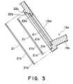
- Figure 3illustrates a sealing structure in which an opening edge of a container for containing toner in the process cartridge is formed into steps.
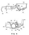
- Figure 4is a sectional view in which the process cartridge of Figure 1 partly disassembled.
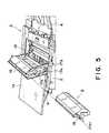
- Figure 5is a perspective view illustrating mounting operation of the process cartridge of Figure 1.
- Figure 6is a perspective view of a toner container provided in the process cartridge of Figure 1.
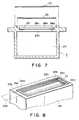
- Figure 7is a sectional view of the sealing structure in which an edge of the opening of the toner cartridge is stepped.
- Figure 8is a schematic perspective view of an opening of the toner container in the process cartridge of Figure 1.
- Figure 1is a sectional view of an electrophotographic image forming apparatus to which a process cartridge is detachably mountable.
- Figure 2is a sectional view of a process cartridge used in the apparatus of Figure 1.
- Figure 3illustrates the sealing structure for the toner container in the process cartridge of Figure 1.
- the process cartridge of Figure 1is shown in a disassembled state.
- Figure 5illustrates the mounting of the process cartridge in the main assembly.
- Figure 6shows an outer appearance of the toner container in the process cartridge of Figure 1.
- Figure 10schematically shows the opening of the toner container in the process cartridge of Figure 1.
- the electrophotographic image forming apparatus Aas shown in Figure 1, using an electrophotographic image forming process, images are formed on a recording material such as a recording sheet of paper, textile, OHP sheet or the like.
- an original reading means 1has an original supporting glass 1a for supporting an original thereon at the top of the main assembly 2 of the apparatus.
- An original cover 1bis rotatably mounted covering the original glass 1a.
- the original supporting glass 1a and the original cover 1bare slidable relative to the main assembly 2 in a horizontal direction in Figure 1 (x direction).
- a lens unit 1cincluding a light source 1c1, a short focus imaging lens array 1c2.
- the originalis placed on the original supporting glass 1a face down on the original supporting surface thereof, and the light source 1c1 is turned on.
- the original supporting glass 1ais moved in the direction X.
- the light reflected from the original 3is projected onto an electrophotographic photosensitive member in the form of a drum (photosensitive drum) of a process cartridge B through the lens array 1c2.
- a recording material 5 contained in a sheet feeding tray 4is fed out by cooperation of a separation pad 6a and a separation roller 6c press-contacted thereto and fed forward by feeding means including registration rollers 6c1 and 6c2.
- the toner image formed on the photosensitive drum 10 in the process cartridge Bis transferred onto the recording material by application of a voltage to the transfer roller 7 functioning as a transfer means.
- the recording material 5is fed to an image fixing means 8 comprising a heater 8a, a fixing rotatable member 8b, and a driving roller press-contacted to the rotatable member 8b.
- the transferred toner imageis fixed on the recording material 5.
- the recording material 5is fed by a pair of discharging rollers 6e1 and 6e2 onto a discharge tray 9.
- the process cartridge Bcontains a rotatable photosensitive drum 10 having a photosensitive layer.
- the surface of the photosensitive memberis uniformly charged by a charging roller 11 (charging means).
- the photosensitive drum 10is exposed to the light reflected by the original and from the reading means 1 through an exposure opening 12, so that a latent image is formed thereon.
- the latent imageis developed by developing means 13 into a toner image.
- the developing device 13comprises a toner container 13a for containing toner, a developing portion 13b for forming the toner image on the photosensitive drum 10, wherein the toner is fed from the toner container 13 into a developing zone 13 by a toner feeding member 13c.
- the developing roller 13e containing a stationary magnet 13d in the developing portion 13bis rotated, a layer of the toner supplied with a triboelectric charge by developing blade 13f is formed on the developing roller 13e.
- the toneris supplied to the photosensitive drum 10 to develop the latent image thereon into a toner image.
- the transfer roller 7is supplied with a voltage having a polarity opposite from that of the toner, so that the toner image is transferred from the photosensitive drum 10 onto the recording material 5.
- the residual toner remaining on the photosensitive drum 10is scraped off by an elastic cleaning blade 14a.
- the toner scraped off by the blade 14ais received by a receiving sheet 14b, and is collected into a residual toner container 14c. In this manner, the residual toner on the photosensitive drum 10 is removed by the cleaning device.
- the cleaning device 14is constituted by the blade 14a, the receiving sheet 14b and the residual toner container 14c.
- the charging roller 11, the exposure opening 12, a toner container 13a for containing the toneris provided in a top frame 15a, and the photosensitive drum 13, the developing portion 13b of the developing device 13 and the cleaning device are provided in the bottom frame 15b.
- the process cartridge Bis constituted by connecting the top and bottom frames 15a and 15b.
- the top frame 15a and the bottom frame 15bare separably engaged by resiliently engaging the claws 15c of the top frame 15a with engaging portions 15d of the bottom frame.
- the process cartridge Bis detachably mounted to a cartridge mounting means 17 of the main assembly.
- an openable cover 16is provided on the top of the apparatus main assembly 2.
- the cover 16is provided with a mounting member 17b having an engaging window 17a in conformity with the configuration of the process cartridge B.
- the operatormanipulates the process cartridge B using the grip 18 into the window 17a, and the cover 16 is then closed.
- a shaft (not shown) of the photosensitive drum 10 projected from the frames 15a and 15b of the process cartridge B and a shaft (not shown) of the developing sleeve 13eis supported on a shaft supporting member 19 of the main assembly 2.
- a protection cover 20 protecting the photosensitive drum 10 of the process cartridge B( Figure 2) is rotated by an unshown mechanism to expose an image transfer region of the photosensitive drum 10 to bring the transfer roller 7 into contact with the drum 10, so that the mounting of the cartridge B is completed.
- the developing device 13When the process cartridge B is mounted in place in the main assembly A, the developing device 13 receives the toner from the toner container 13a into the developing portion 13b. However, in the case of fresh (non-used) process cartridge B, the opening 13a1 of the toner container 13a is sealed by a sealing member 21 to prevent moisture absorption and scattering of the toner particles during transportation or in storage.
- the sealing structurewill be described.
- the opening 13a1 of the toner container 13ais sealed by sticking a sealing member 21 to cover the opening 13a1 for supplying the toner to the developing portion 13b.
- the sealing member 21comprises a cover film 21a of uniaxial oriented polyethylene film or uniaxial oriented polypropylene film or the like and a flexible tear tape 21b of bi-axial oriented polyester film and bi-axial oriented polypropylene film or the like, which is integrally bonded thereto.
- the bonding between the cover film 21a and the tear tape 21b, and the bonding between the cover film 21a and the edge of the container 13a defining the opening 13a1are both effected by heat fusing. They may be effected by bonding material.
- the tear tape 21bextends from one longitudinal end 13a2 of the opening 13a1 (left hand end in Figure 6) to the other end 13a3 (right hand end in Figure 6).
- the tape 21bis folded back at the end 13a3, and is extended along the group 18b formed at a side end of the top frame 15a and is projected out of the process cartridge B.
- the tear tape 21bprior to the mounting of the process cartridge B into the image forming apparatus A by the operator, the projection 21b1 is pulled out, by which the cover film 21a is torn along the tear tape 21b, thus open the opening 13a1.
- the toner contained in the toner container 13ais permitted to be fed to the developing zone 13b.
- a toner filling port 13a4functions to supply the toner into the container 13a, after the opening 13a1 sealed by the sealing member 21.
- Figure 3is an enlarged view of a part E of the process cartridge B in Figure 2.
- the edge of the opening 13a1 of the toner container 13ais provided with three sealing surfaces 22a, 22b and 22c in the form of steps, that is, having different levels. More particularly, the edge portion of the opening has a first sealing surface 22a, a second sealing surface 22b one step above and outside thereof, and a third sealing surface 22c further higher by one step, and further outside thereof.
- the sealing surfaces 22a, 22b and 22ccan be sealed by sealing members 21 having corresponding size.
- the sealing members 21can be fused on the sealing surfaces 22a, 22b and 22c constituting flat steps.
- the sealing member 21is fused on the first sealing surface 22a to seal the opening 13a1, and it is delivered out.
- the process cartridge Bis intended to be collected after use and to be reused.
- the used process cartridges Bare collected back in co-operation with users and service persons or the like. They are transported to a recycling plant, where the cartridge B is disassembled, and various parts are taken out. The parts are inspected, and are classified into reusable parts and parts not to be reused because of damages or service lives. Only the reusable parts are cleaned by air gun or the like, to permit reuse thereof. Further inspections are carried out, and satisfactory parts are further inspected as to whether the functions thereof are satisfactorily refreshed or not. Only the parts passing through the inspections are used to produce recycled process cartridge.
- the first sealing surface 22ais not used in the second assembling, but the sealing member 21 is fused on the second sealing surface 22b to seal the opening 13a1.
- the first and second sealing surfaces 22a and 22bare not used, but the sealing member 21 is fused on the third sealing surface 22c to seal the opening 13a1.
- the top frame 15a and the bottom frame 15bare of plastic material such as high impact styrene material, and if they are used for a long term, damage, deformation, deterioration or the like occurs. For this reason, in this embodiment, when they exceeds to use limit, they are crushed and reused as blank material. As an indication for this discrimination, it is desirable that how many times the top frame 15a is used is known.
- the number of usecan be readily known. For example, it may be predetermined as described hereinbefore that the first sealing surface 22a is used for the first assembling, the second sealing surface 22b is used for the second assembling, and the third sealing surface 22c is used for the third assembling. By doing so, the number of past uses can be easily discriminated by checking the existence of the remaining cover film 21a on the sealing surfaces, upon the recycling.
- the sealing member 21may be provided with a mark or a sign indicative of the number of uses, or the configuration and/or the color thereof may be made different. By doing so, the recycling operator can further easily discriminate the number of uses of the top frame 15a. This eliminates the necessity for particularly provision of marks or the like indicative of the number of uses for every reuse.
- the number of steps of the sealing portionis three two permit three sealings.
- the numberis not limiting, and it may be determined by one skilled in the art properly in accordance with the limit number of uses for the top frame 15a.
- the sealing member 21By forming the sealing surface into a configuration for permitting repeated use for the sealing surface, the sealing member 21 can be easily mounted a plurality of times, thus permitting easy recycling of the frame.
- the opening of the toner container 13a of the process cartridge to be mounted into the main assembly of the image forming apparatusis sealed.
- the present inventionis not limited to the process cartridge.
- the photosensitive drum, the charging device, the developing device, the cleaning device and the transfer deviceare directly mounted on the main assembly.
- the toneris supplied from a toner hopper into a developing device.
- the toner in the toner hopperis used up, it has to be replenished.
- a toner cartridge CUpon the toner replenishment, as shown in Figure 7, a toner cartridge C is used.
- a sealing member 25 similar to the sealing member 21 as in the forgoing embodimentsis fused by heat to seal the opening 24a of the container 24 containing the toner. By doing so, the moisture absorption or scattering of the toner in the container 24, can be prevented.
- the sealing member 25Upon replenishment of the toner into the main assembly, the sealing member 25 is removed from the opening 24a by the operator to permit the toner is supplied into the toner hopper from the container 24.
- an edge of the opening 24a of the toner cartridge Cis formed into steps as in Embodiment 1 to provide a plurality of sealing surfaces 26a, 26b and 26c.
- the sealing member 25can be fused by heat a plurality of times, thus permitting easy recycling.
- the structureis not limited to the stepped structure of the sealing surface, but the sealing area may be increased or decreased or made different depending on the number of seals as in Embodiment 2.
- a ribmay be formed, and upon the recycling, the rib may be partly cut out by a predetermined amount to permit the sealing member 25 to be fused by heat on the fresh surface.
- the structure for permitting easy discrimination of the number of uses as in the foregoing embodimentsthe recycling operation is made further easier.
- the process cartridge Bcontains the toner container 13a in the top frame 15a, and the developing portion 13b is provided in the bottom frame 15b (so-called top-bottom separable type).
- the present inventionis not limited to this type, but is applicable to a so-called left-right separable cartridge in which the toner container and the developing portion are in one frame, and the photosensitive drum and the cleaning means are in the other frame.
- the useis made with a sealing member having bonded integral cover film and tear tape, in which the cover film is torn by pulling the tear tape (so-called tear tape type).
- tear tape typea sealing member having bonded integral cover film and tear tape, in which the cover film is torn by pulling the tear tape
- the sealing memberis not limited to this type.
- the tear tape, the cover film or the likemay be directly fused on the sealing surface (so-called easy peel type).
- the sealing method for the openingmay be, a so-called tear tape type, so-called easy peel type or the like.
- the sealing memberis mounted to the edge of the container opening, and is fused thereon.
- the heat fusingis not a limiting feature, but use of a bonding or adhesive material, high frequency fusing or ultrasonic wave fusing or the like are usable.
- the process cartridge Bis usable for monochromatic color formation as described hereinbefore, but is also usable for multi-color (two color image formation, three color image formation or a full-color) image formation by using a plurality of developing means.
- the developing methoda known two-component magnetic brush developing method, cascade developing method, touch-down developing method, cloud developing method or the like, are usable.
- the electrophotographic photosensitive memberhas a photoconductive member which may be an amorphous silicon, amorphous selenium, zinc oxide, titanium oxide, organic photoconductor (OHP) or the like.
- the photosensitive membermay be in the form of a drum, belt or another rotatable type or a sheet or the like. Usually, it is a drum or belt.
- a photoconductive materialis evaporated or applied and so on on an aluminum alloy or the like cylinder.
- the charging meansis in the form of so-called contact method.
- a known corona dischargerhaving a tungsten wire, a metal shield of aluminum or the like at three sides, wherein a high voltage is applied to the tungsten wire, so that positive or negative ions to the surface of the photosensitive drum to uniformly charge it.
- examples of usable typeincludes a blade type (charging blade), pad type, block type, rod type, wire type or the like.
- fur brush or magnetic brush or the likeis usable.
- the process cartridge described hereinbeforecomprises an image bearing member such as an electrophotographic photosensitive member or the like and at least one process means. More particularly, the process cartridge may contain an image bearing member and charging means as a unit into a cartridge detachably mountable to the main assembly, for example. In another example, an image bearing member and developing means are contained as a unit into a cartridge detachably mountable to the main assembly of the apparatus. In a further example, an image bearing member and cleaning means are contained as a unit into a cartridge detachably mountable to the main assembly. Even further example, it may contain an image bearing member and two or more of the process means as a unit into a cartridge which is detachably mountable to an image forming apparatus.
- the image forming apparatushas been described as an electrophotographic copying machine.
- the present inventionis not limited to this, but is applicable to a laser beam printer, facsimile machine, a word processor or other image forming machines.
- a sealing portion to be sealed by a sealing membera plurality of times, and therefore, the opening can be resealed by a fresh sealing member after the old sealing member is removed.
- the used cartridgeis reusable.
Landscapes
- Physics & Mathematics (AREA)
- General Physics & Mathematics (AREA)
- Engineering & Computer Science (AREA)
- Computer Vision & Pattern Recognition (AREA)
- Life Sciences & Earth Sciences (AREA)
- Sustainable Development (AREA)
- Electrophotography Configuration And Component (AREA)
- Dry Development In Electrophotography (AREA)
Description
- The present invention relates to a tonercartridge for containing toner usable with anelectrophotographic image forming apparatus, a processcartridge detachably mountable to the image formingapparatus, and an electrophotographic image formingapparatus using the process cartridge.
- Here, the electrophotographic image formingapparatus means an apparatus for forming images on arecording material through an electrophotographicimage formation process, such as anelectrophotographic copying machine, anelectrophotographic printer, an electrophotographicfacsimile machine or the like.
- The process cartridge is a unified cartridgecontaining an electrophotographic photosensitivemember and charging means, developing means and/orcleaning means, which is detachably mountable as aunit relative to the main assembly of image formingapparatus. Therefore, it contains as a unit anelectrophotographic photosensitive member and at leastone of charging means, developing means and cleaningmeans. In another example of the process cartridge,it contains the developing means and the electrophotographic photosensitive member.
- The toner cartridge is for supplying thetoner into the image forming apparatus when the tonertherein is consumed.
- In the electrophotographic image formingapparatus, the electrophotographic photosensitivemember is uniformly charged by charging means and isexposed to imagewise light in accordance with imageinformation, by which a latent image is formed on theelectrophotographic photosensitive member. The latentimage is developed by developing means. Thereafter,the toner image formed by the developing means istransferred onto a recording material, thus forming animage on the recording material. In such anelectrophotographic image forming apparatus, it isusual that an expert service person carries out themaintenance operation. To avoid this, a detachablymountable process cartridge is used. By the userexchanging the process cartridge, the maintenance ofthe apparatus is made much easier. The processcartridge type apparatus has been put into practice.Recently, reuse of parts is considered and started.
- EP-A-0632342 describes a seal arrangement for atoner container wherein the container is resealed byapplying a new seal to the same sealing area of thecontainer as the previous seal. The residue of theprevious seal is removed, to provide an even faying surface for the new seal to be bonded to. The importanceof cleaning the surface to avoid irregularities (referredto as a "stepped portion" of the mounting surface)between areas having residue and areas of no residue isemphasised in EP-A-0632342 to prevent leaks at such"stepped portions" of a mounting surface.
- US-A-4930684 describes a toner container having aremovable and replaceable sealing member slidable betweena pair of channels and resiliently sealed therein.
- JP-A-4293066 describes a toner container formingpart of a larger structure such as a process cartridge.The joint plane between a removable seal and the tonercontainer is offset from the joint plane at which thetoner container is joined to the larger structure, sothat joining the toner container to the structure doesnot affect the joint between the toner container and theseal.
- EP-A-0661609 discloses recycling a toner containerby replacing a seal which has been peeled off by bondinga fresh seal in its placed with hot-melt adhesive.
- The present invention provides a further developmentof the process cartridge. In addition, the presentinvention is applicable not only to the process cartridgebut also to a toner cartridge for containing toner.
- Accordingly, it is a concern of thepresent invention to provide a toner cartridge,process cartridge and an electrophotographic imageforming apparatus with which recycling of materials iseasy.
- It is another concern of the present inventionto provide a toner cartridge, process cartridge and anelectrophotographic image forming apparatus in whichthe toner is prevented from leaking from the cartridgeframe after the recycling thereof.
- It is a further concern of the presentinvention to provide a toner cartridge, a processcartridge and an electrophotographic image formingapparatus in which sealing members can be repeatedlymounted.
- An embodiment of the presentinvention provides a toner cartridge, a processcartridge and an electrophotographic image formingapparatus having a seal mounting portion capable ofpermitting an opening of a toner container to besealed a plurality of times in accordance with
claims - Another embodiment of the presentinvention provides a method of recycling a used toner containerin which after a sealing member is removedfrom a container opening, a fresh sealing member can be mounted to the same opening in accordance with
claim 12. - Other features andadvantages of the present invention will become moreapparent upon a consideration of the followingdescription of the preferred embodiments of thepresent invention taken in conjunction with theaccompanying drawings.
- Figure 1 is a sectional view of an imageforming apparatus loaded with a process cartridge,according to an embodiment of the present invention.
- Figure 2 is a sectional view of a processcartridge shown in Figure 1.
- Figure 3 illustrates a sealing structure inwhich an opening edge of a container for containingtoner in the process cartridge is formed into steps.
- Figure 4 is a sectional view in which theprocess cartridge of Figure 1 partly disassembled.
- Figure 5 is a perspective view illustratingmounting operation of the process cartridge of Figure1.
- Figure 6 is a perspective view of a tonercontainer provided in the process cartridge of Figure1.
- Figure 7 is a sectional view of the sealingstructure in which an edge of the opening of the tonercartridge is stepped.
- Figure 8 is a schematic perspective view ofan opening of the toner container in the processcartridge of Figure 1.
- Embodiments of the present invention will bedescribed in detail.
- Referring to Figures 1 - 6, the descriptionwill be made as to a process cartridge, as an example,according to
Embodiment 1 of the present invention. - Figure 1 is a sectional view of anelectrophotographic image forming apparatus to which aprocess cartridge is detachably mountable. Figure 2is a sectional view of a process cartridge used in theapparatus of Figure 1. Figure 3 illustrates the sealing structure for the toner container in theprocess cartridge of Figure 1. In Figure 4, theprocess cartridge of Figure 1 is shown in adisassembled state.
- Figure 5 illustrates the mounting of theprocess cartridge in the main assembly. Figure 6shows an outer appearance of the toner container inthe process cartridge of Figure 1. Figure 10schematically shows the opening of the toner containerin the process cartridge of Figure 1.
- The description will first be made as to thegeneral arrangement of the image forming apparatusreferring to Figures 1 - 5, and the description willbe made as to the sealing structure for the tonercontainer referring to Figures 3 and 10.
- The electrophotographic image formingapparatus A, as shown in Figure 1, using anelectrophotographic image forming process, images areformed on a recording material such as a recordingsheet of paper, textile, OHP sheet or the like.
- First, an original reading means 1 has anoriginal supporting
glass 1a for supporting anoriginal thereon at the top of themain assembly 2 ofthe apparatus. Anoriginal cover 1b is rotatablymounted covering theoriginal glass 1a. The originalsupportingglass 1a and theoriginal cover 1b are slidable relative to themain assembly 2 in ahorizontal direction in Figure 1 (x direction). Onthe other hand, at an upper portion of themainassembly 2 and below the original supportingglass 1a,there is provided alens unit 1c, including a lightsource 1c1, a short focus imaging lens array 1c2. Theoriginal is placed on the original supportingglass 1aface down on the original supporting surface thereof,and the light source 1c1 is turned on. Then, theoriginal supportingglass 1a is moved in the directionX. The light reflected from the original 3 isprojected onto an electrophotographic photosensitivemember in the form of a drum (photosensitive drum) ofa process cartridge B through the lens array 1c2. - In synchronism with the exposure to theoriginal image light, a
recording material 5 containedin asheet feeding tray 4 is fed out by cooperation ofaseparation pad 6a and a separation roller 6c press-contactedthereto and fed forward by feeding meansincluding registration rollers 6c1 and 6c2. The tonerimage formed on thephotosensitive drum 10 in theprocess cartridge B is transferred onto the recordingmaterial by application of a voltage to thetransferroller 7 functioning as a transfer means. Then, therecording material 5 is fed to an image fixing means 8comprising aheater 8a, a fixingrotatable member 8b,and a driving roller press-contacted to therotatable member 8b. By passing the recording material throughthe nip formed between therotatable member 8b and thedriving roller 8c, the transferred toner image isfixed on therecording material 5. Therecordingmaterial 5 is fed by a pair of discharging rollers 6e1and 6e2 onto adischarge tray 9. - On the other hand, the process cartridge B,as shown in Figure 2, contains a rotatable
photosensitive drum 10 having a photosensitive layer.During the rotation thereof, the surface of thephotosensitive member is uniformly charged by acharging roller 11 (charging means). Thephotosensitive drum 10 is exposed to the lightreflected by the original and from the reading means 1through anexposure opening 12, so that a latent imageis formed thereon. The latent image is developed bydevelopingmeans 13 into a toner image. - The developing
device 13 comprises atonercontainer 13a for containing toner, a developingportion 13b for forming the toner image on thephotosensitive drum 10, wherein the toner is fed fromthetoner container 13 into a developingzone 13 by atoner feeding member 13c. The developingroller 13econtaining astationary magnet 13d in the developingportion 13b is rotated, a layer of the toner suppliedwith a triboelectric charge by developingblade 13f isformed on the developingroller 13e. The toner is supplied to thephotosensitive drum 10 to develop thelatent image thereon into a toner image. - The
transfer roller 7 is supplied with avoltage having a polarity opposite from that of thetoner, so that the toner image is transferred from thephotosensitive drum 10 onto therecording material 5.The residual toner remaining on thephotosensitivedrum 10 is scraped off by anelastic cleaning blade 14a. The toner scraped off by theblade 14a isreceived by a receivingsheet 14b, and is collectedinto aresidual toner container 14c. In this manner,the residual toner on thephotosensitive drum 10 isremoved by the cleaning device. Thecleaning device 14 is constituted by theblade 14a, the receivingsheet 14b and theresidual toner container 14c. - As shown in Figure 4, the charging roller 11,the exposure opening 12, a
toner container 13a forcontaining the toner is provided in atop frame 15a,and thephotosensitive drum 13, the developingportion 13b of the developingdevice 13 and the cleaningdevice are provided in thebottom frame 15b. Theprocess cartridge B is constituted by connecting thetop andbottom frames top frame 15aand thebottom frame 15b are separably engaged byresiliently engaging theclaws 15c of thetop frame 15a with engagingportions 15d of the bottom frame. - The process cartridge B is detachably mounted to a cartridge mounting means 17 of the main assembly.As shown in Figure 5, an
openable cover 16 is providedon the top of the apparatusmain assembly 2. Thecover 16 is provided with a mountingmember 17b havingan engagingwindow 17a in conformity with theconfiguration of the process cartridge B. Upon themounting of the process cartridge B, the operatormanipulates the process cartridge B using thegrip 18into thewindow 17a, and thecover 16 is then closed.By doing so, a shaft (not shown) of thephotosensitivedrum 10 projected from theframes sleeve 13e is supported on ashaftsupporting member 19 of themain assembly 2. At thistime, aprotection cover 20 protecting thephotosensitive drum 10 of the process cartridge B(Figure 2) is rotated by an unshown mechanism toexpose an image transfer region of thephotosensitivedrum 10 to bring thetransfer roller 7 into contactwith thedrum 10, so that the mounting of thecartridge B is completed. - When the process cartridge B is mounted inplace in the main assembly A, the developing
device 13receives the toner from thetoner container 13a intothe developingportion 13b. However, in the case offresh (non-used) process cartridge B, the opening 13a1 of thetoner container 13a is sealed by a sealingmember 21 to prevent moisture absorption andscattering of the toner particles duringtransportation or in storage. The sealing structurewill be described. - As shown in Figure 6, the opening 13a1 of the
toner container 13a is sealed by sticking a sealingmember 21 to cover the opening 13a1 for supplying thetoner to the developingportion 13b. The sealingmember 21 comprises acover film 21a of uniaxialoriented polyethylene film or uniaxial orientedpolypropylene film or the like and aflexible teartape 21b of bi-axial oriented polyester film and bi-axialoriented polypropylene film or the like, whichis integrally bonded thereto. In this embodiment, thebonding between thecover film 21a and thetear tape 21b, and the bonding between thecover film 21a andthe edge of thecontainer 13a defining the opening13a1, are both effected by heat fusing. They may beeffected by bonding material. - The
tear tape 21b, as shown in Figure 6,extends from one longitudinal end 13a2 of the opening13a1 (left hand end in Figure 6) to the other end 13a3(right hand end in Figure 6). Thetape 21b is foldedback at the end 13a3, and is extended along the group18b formed at a side end of thetop frame 15a and isprojected out of the process cartridge B. Thetear tape 21b, prior to the mounting of the processcartridge B into the image forming apparatus A by theoperator, the projection 21b1 is pulled out, by whichthecover film 21a is torn along thetear tape 21b,thus open the opening 13a1. The toner contained inthetoner container 13a is permitted to be fed to thedevelopingzone 13b. In Figure 6, a toner fillingport 13a4 functions to supply the toner into thecontainer 13a, after the opening 13a1 sealed by thesealingmember 21. - Referring to Figure 3, the description willbe made as to the edge of the opening 13a1 of the
toner container 13a sealed by the sealingmember 21.Figure 3 is an enlarged view of a part E of theprocess cartridge B in Figure 2. - As shown in Figure 3, the edge of the opening13a1 of the
toner container 13a, is provided withthree sealingsurfaces first sealing surface 22a, asecond sealing surface 22b one step above and outside thereof, and athirdsealing surface 22c further higher by one step, andfurther outside thereof. The sealing surfaces 22a,22b and 22c can be sealed by sealingmembers 21 havingcorresponding size. The sealingmembers 21 can befused on the sealing surfaces 22a, 22b and 22c constituting flat steps. - In the initial assembling of the processcartridge B, the sealing
member 21 is fused on thefirst sealing surface 22a to seal the opening 13a1,and it is delivered out. The process cartridge B isintended to be collected after use and to be reused. - The recycling steps will be describedbriefly. The used process cartridges B are collectedback in co-operation with users and service persons orthe like. They are transported to a recycling plant,where the cartridge B is disassembled, and variousparts are taken out. The parts are inspected, and areclassified into reusable parts and parts not to bereused because of damages or service lives. Only thereusable parts are cleaned by air gun or the like, topermit reuse thereof. Further inspections are carriedout, and satisfactory parts are further inspected asto whether the functions thereof are satisfactorilyrefreshed or not. Only the parts passing through theinspections are used to produce recycled processcartridge.
- Upon the initial use of the process cartridgeB in which the operator removes the sealing
member 21sealing the opening 13a1 on thefirst sealing surface 22a, a part of thecover film 21a remains on thefirstsealing surface 22a. In order to fuse again on thesealingsurface 22a, the remaining film has to be completely removed, and this operation is cumbersome. - Therefore, when the process cartridge B isrecycled, the
first sealing surface 22a is not used inthe second assembling, but the sealingmember 21 isfused on thesecond sealing surface 22b to seal theopening 13a1. - Furthermore, for the third use, the first andsecond sealing surfaces 22a and 22b are not used, butthe sealing
member 21 is fused on thethird sealingsurface 22c to seal the opening 13a1. - Thus, in this embodiment, three sealingsurfaces are prepared for mounting the sealing
member 21 so as to permit the opening 13a1 to be sealed threetimes without the necessity for removing the rest ofthe tape on the sealing surface. Therefore, therecycling of thetop frame 15a is made easy. - The
top frame 15a and thebottom frame 15bare of plastic material such as high impact styrenematerial, and if they are used for a long term,damage, deformation, deterioration or the like occurs.For this reason, in this embodiment, when they exceedsto use limit, they are crushed and reused as blankmaterial. As an indication for this discrimination,it is desirable that how many times thetop frame 15ais used is known. - According to this embodiment, bypredetermining the order of fusing of the sealing
members 21 and sealingsurfaces first sealing surface 22a is used for the firstassembling, thesecond sealing surface 22b is used forthe second assembling, and thethird sealing surface 22c is used for the third assembling. By doing so,the number of past uses can be easily discriminated bychecking the existence of the remainingcover film 21aon the sealing surfaces, upon the recycling. - In order to made the discrimination furthereasier, the sealing
member 21 may be provided with amark or a sign indicative of the number of uses, orthe configuration and/or the color thereof may be madedifferent. By doing so, the recycling operator canfurther easily discriminate the number of uses of thetop frame 15a. This eliminates the necessity forparticularly provision of marks or the like indicativeof the number of uses for every reuse. - In the foregoing embodiment, the number ofsteps of the sealing portion is three two permit threesealings. However, the number is not limiting, andit may be determined by one skilled in the artproperly in accordance with the limit number of usesfor the
top frame 15a. - By forming the sealing surface into aconfiguration for permitting repeated use for the sealing surface, the sealing
member 21 can be easilymounted a plurality of times, thus permitting easyrecycling of the frame. - In the previous embodiment, the opening of the
toner container 13a of the process cartridge to bemounted into the main assembly of the image formingapparatus, is sealed. However, the present inventionis not limited to the process cartridge. - In an ordinary electrophotographic imageforming apparatus such as a copying machine, thephotosensitive drum, the charging device, thedeveloping device, the cleaning device and thetransfer device are directly mounted on the main assembly. In such a type, the toner is supplied froma toner hopper into a developing device. When thetoner in the toner hopper is used up, it has to bereplenished.
- Upon the toner replenishment, as shown inFigure 7, a toner cartridge C is used. For such atoner cartridge C, a sealing
member 25 similar to thesealingmember 21 as in the forgoing embodiments isfused by heat to seal theopening 24a of thecontainer 24 containing the toner. By doing so, the moistureabsorption or scattering of the toner in thecontainer 24, can be prevented. Upon replenishment of the tonerinto the main assembly, the sealingmember 25 isremoved from theopening 24a by the operator to permitthe toner is supplied into the toner hopper from thecontainer 24. - Therefore, an edge of the
opening 24a of thetoner cartridge C, as shown in Figure 7, is formedinto steps as inEmbodiment 1 to provide a pluralityof sealingsurfaces member 25 can be fused by heat a plurality of times,thus permitting easy recycling. - Also in the case of the toner cartridge C,the structure is not limited to the stepped structureof the sealing surface, but the sealing area may beincreased or decreased or made different depending on the number of seals as in
Embodiment 2. Similarly toEmbodiment 3, a rib may be formed, and upon therecycling, the rib may be partly cut out by apredetermined amount to permit the sealingmember 25to be fused by heat on the fresh surface. - Additionally, also in the case of the tonercartridge C, the structure for permitting easydiscrimination of the number of uses as in theforegoing embodiments, the recycling operation is madefurther easier.
- In the foregoing embodiments, the processcartridge B contains the
toner container 13a in thetop frame 15a, and the developingportion 13b isprovided in thebottom frame 15b (so-called top-bottomseparable type). However, the present invention isnot limited to this type, but is applicable to a so-calledleft-right separable cartridge in which thetoner container and the developing portion are in oneframe, and the photosensitive drum and the cleaningmeans are in the other frame. - In the foregoing embodiments, the use is madewith a sealing member having bonded integral coverfilm and tear tape, in which the cover film is torn bypulling the tear tape (so-called tear tape type).However, the sealing member is not limited to thistype. For example, the tear tape, the cover film or the like may be directly fused on the sealing surface(so-called easy peel type). Thus, the sealing methodfor the opening may be, a so-called tear tape type,so-called easy peel type or the like.
- In the foregoing embodiments, the sealingmember is mounted to the edge of the containeropening, and is fused thereon. However, the heatfusing is not a limiting feature, but use of a bondingor adhesive material, high frequency fusing orultrasonic wave fusing or the like are usable. Theprocess cartridge B is usable for monochromaticcolor formation as described hereinbefore, but isalso usable for multi-color (two color imageformation, three color image formation or a full-color)image formation by using a plurality ofdeveloping means.
- As for the developing method, a known two-componentmagnetic brush developing method, cascadedeveloping method, touch-down developing method, clouddeveloping method or the like, are usable.
- The electrophotographic photosensitive memberhas a photoconductive member which may be an amorphoussilicon, amorphous selenium, zinc oxide, titaniumoxide, organic photoconductor (OHP) or the like. Thephotosensitive member may be in the form of a drum,belt or another rotatable type or a sheet or the like.Usually, it is a drum or belt. In the case of the drum type photosensitive member, a photoconductivematerial is evaporated or applied and so on on analuminum alloy or the like cylinder.
- In the first embodiment, the charging meansis in the form of so-called contact method. However,a known corona discharger having a tungsten wire, ametal shield of aluminum or the like at three sides,wherein a high voltage is applied to the tungstenwire, so that positive or negative ions to thesurface of the photosensitive drum to uniformly chargeit.
- As for the charging means, in addition to theroller type, examples of usable type includes a bladetype (charging blade), pad type, block type, rod type,wire type or the like.
- As for the method of cleaning to remove theresidual toner from the photosensitive drum, fur brushor magnetic brush or the like is usable.
- The process cartridge described hereinbeforecomprises an image bearing member such as anelectrophotographic photosensitive member or the likeand at least one process means. More particularly,the process cartridge may contain an image bearingmember and charging means as a unit into a cartridgedetachably mountable to the main assembly, forexample. In another example, an image bearing memberand developing means are contained as a unit into a cartridge detachably mountable to the main assembly ofthe apparatus. In a further example, an image bearingmember and cleaning means are contained as a unit intoa cartridge detachably mountable to the main assembly.Even further example, it may contain an image bearingmember and two or more of the process means as a unitinto a cartridge which is detachably mountable to animage forming apparatus.
- In the foregoing embodiments, the imageforming apparatus has been described as anelectrophotographic copying machine. However, thepresent invention is not limited to this, but isapplicable to a laser beam printer, facsimilemachine, a word processor or other image formingmachines.
- As described in the foregoing, according tothe present invention, around an opening of a tonercontainer, a sealing portion to be sealed by a sealingmember a plurality of times, and therefore, theopening can be resealed by a fresh sealing memberafter the old sealing member is removed. By doing so,the used cartridge is reusable.
- By the structure for permitting the easydiscrimination of the number of sealing actions,the recycling operation for the cartridge is easy.
- While the invention has been described withreference to the structures disclosed herein, it is not confined to the details set forth and thisapplication is intended to cover such modifications orchanges as may come withinthe scope of the following claims.
Claims (14)
- A process cartridge (B) detachably mountable to amain assembly (2) of an image forming apparatus,comprising:an electrophotographic photosensitive member (10);process means (11, 13, 14) actable on saidphotosensitive member;a toner container (13a) for containing toner fordeveloping a latent image formed on saidelectrophotographic photosensitive member, said tonercontainer having an opening (13a1) for permitting supplyof the toner to a developing portion (13b) therefrom;a sealing member (21) for sealing the opening; anda seal mounting portion (22a, 22b, 22c) includinga plurality of stepped portions on any one of which thesealing member is selectively mountable for permitting the mounting of the sealing member a plurality of times.
- A process cartridge according to claim 1, whereinsaid sealing member (21) is mounted onto said steppedportion of said seal mounting portion by heat fusing,with adhesive material or with ultrasonic wave bonding.
- A process cartridge according to claim 1 or claim2, wherein said sealing member (21) includes a cover film(21a) and a tear tape (21b), wherein the cover tape istorn by pulling the tear tape to open the opening.
- A process cartridge according to any precedingclaim, wherein said process means includes charging means(11), developing means (13) or cleaning means (14).
- An electrophotographic image forming apparatus forforming an image on a recording material, to which aprocess cartridge (B) is detachably mountable,comprising:mounting means for detachably mounting to a mainassembly (2) of an image forming apparatus a processcartridge including an electrophotographic photosensitivemember (10); process means (11, 13, 14) actable on saidphotosensitive member; a toner container (13a) forcontaining toner for developing a latent image formed onsaid electrophotographic photosensitive member, saidtoner container having an opening (13a1) for permittingsupply of the toner to a developing portion (13b)therefrom; a sealing member (21) for sealing the opening;anda seal mounting portion (22a, 22b, 22c) includinga plurality of stepped portions to any one of which thesealing member is selectively mountable for permitting the mounting of the sealing member a plurality of times;transfer means (7) for transferring, onto therecording material, the toner image formed on saidphotosensitive member in said process cartridge mountedon said mounting means; andfeeding means (6) for feeding the recording material.
- An apparatus according to claim 5, wherein saidimage forming apparatus is an electrophotographic copyingmachine.
- An apparatus according to claim 5, wherein saidimage forming apparatus is a laser beam printer.
- An apparatus according to claim 5, wherein saidimage forming apparatus is a facsimile machine.
- A toner cartridge (C) for supplying toner to anelectrophotographic image forming apparatus for formingan image on a recording material (5) by developing alatent image formed on an electrophotographicphotosensitive member (10) into a toner image and bytransferring the toner image onto the recording material,comprising:a toner containing portion (24) for containing thetoner, the toner containing portion having an opening(24a) for supplying the toner to said electrophotographicimage forming apparatus;a sealing member (25) for sealing the opening; anda seal mounting portion (26a, 26b, 26c) includinga plurality of stepped portions on any one of which thesealing member (25) is selectively mountable for permittingthe mounting of the sealing member a plurality of times.
- A toner cartridge (C) according to claim 9, whereinsaid sealing member (25) is mounted onto said sealmounting portion (26a, 26b, 26c) by heat fusing, withadhesive material or with ultrasonic wave bonding.
- A toner cartridge (C) according to claim 9 or 10,wherein said sealing member includes a cover film and atear tape, wherein the cover tape is torn by pulling thetear tape to open the opening.
- A method of recycling a used toner container inwhich toner had been retained within the container by aremovable sealing member extending over an opening in thecontainer and secured to a first one of a plurality ofstepped locations on the container surrounding theopening, comprising refilling the container with tonervia the opening and resealing the opening with a secondremovable sealing member by securing the second sealing memberto a second one of said plurality of stepped locationsaround the opening which is different from the firstlocation at which the original sealing member was securedto the container.
- A method according to claim 12, wherein the tonercontainer is incorporated in a process cartridge for anelectrophotographic image reproducing apparatus after therefilling and resealing steps.
- A method according to claim 12, wherein the tonercontainer forms part of a process cartridge for anelectrophotographic image reproducing apparatus.
Applications Claiming Priority (6)
| Application Number | Priority Date | Filing Date | Title |
|---|---|---|---|
| JP3699194 | 1994-03-08 | ||
| JP36991/94 | 1994-03-08 | ||
| JP3699194 | 1994-03-08 | ||
| JP3694395 | 1995-02-24 | ||
| JP7036943AJPH07302034A (en) | 1994-03-08 | 1995-02-24 | Toner cartridge, process cartridge, and electrophotographic image forming apparatus |
| JP36943/95 | 1995-02-24 |
Publications (3)
| Publication Number | Publication Date |
|---|---|
| EP0671670A2 EP0671670A2 (en) | 1995-09-13 |
| EP0671670A3 EP0671670A3 (en) | 1996-03-27 |
| EP0671670B1true EP0671670B1 (en) | 2000-07-19 |
Family
ID=26376049
Family Applications (1)
| Application Number | Title | Priority Date | Filing Date |
|---|---|---|---|
| EP95301465AExpired - LifetimeEP0671670B1 (en) | 1994-03-08 | 1995-03-07 | Toner cartridge, process cartridge, electrophotographic image forming apparatus and method of recycling a toner cartridge |
Country Status (5)
| Country | Link |
|---|---|
| US (1) | US5585902A (en) |
| EP (1) | EP0671670B1 (en) |
| JP (1) | JPH07302034A (en) |
| CN (1) | CN1116734A (en) |
| DE (1) | DE69518029D1 (en) |
Families Citing this family (43)
| Publication number | Priority date | Publication date | Assignee | Title |
|---|---|---|---|---|
| JP2877728B2 (en)* | 1994-04-28 | 1999-03-31 | キヤノン株式会社 | Process cartridge and image forming apparatus |
| JP3492129B2 (en)* | 1996-01-09 | 2004-02-03 | キヤノン株式会社 | Process cartridge, developing device, and electrophotographic image forming device |
| JP3445069B2 (en)* | 1996-07-24 | 2003-09-08 | キヤノン株式会社 | Developing unit, process cartridge, and image forming apparatus |
| US6097907A (en)* | 1996-10-02 | 2000-08-01 | Canon Kabushiki Kaisha | Developer container, process cartridge, developer sealing member and sealing method |
| US5839027A (en)* | 1997-06-30 | 1998-11-17 | Ravi & Associates | Magnet less sealable developer cartridge |
| US6044238A (en)* | 1997-10-17 | 2000-03-28 | Nu-Kote International, Inc. | Replacement seal assembly for a toner cartridge |
| JP3083091B2 (en)* | 1997-12-09 | 2000-09-04 | キヤノン株式会社 | Seal member for developer storage container, developer storage container, developing device, process cartridge, and image forming apparatus |
| JP3728097B2 (en)* | 1998-04-24 | 2005-12-21 | キヤノン株式会社 | Process cartridge |
| JP3817369B2 (en)* | 1998-05-22 | 2006-09-06 | キヤノン株式会社 | Developing device, process cartridge including the developing device, and image forming apparatus |
| JP3604919B2 (en)* | 1998-08-31 | 2004-12-22 | キヤノン株式会社 | Color electrophotographic image forming apparatus and developing cartridge |
| JP3437460B2 (en) | 1998-08-31 | 2003-08-18 | キヤノン株式会社 | Toner container |
| JP3320398B2 (en) | 1999-05-20 | 2002-09-03 | キヤノン株式会社 | Process cartridge and electrophotographic image forming apparatus |
| JP3748506B2 (en) | 1999-05-20 | 2006-02-22 | キヤノン株式会社 | Process cartridge and process cartridge assembly method |
| CN1237416C (en) | 2000-06-09 | 2006-01-18 | 佳能株式会社 | Connection method between developing device, process cartridge, developing frame, and developer frame, and flexible seal |
| CN100422865C (en)* | 2000-07-21 | 2008-10-01 | 株式会社理光 | Image forming apparatus and toner storage container |
| US6301456B1 (en) | 2000-09-22 | 2001-10-09 | Lexmark International, Inc. | Method and apparatus for inserting a cartridge into an image forming apparatus |
| JP2002182446A (en) | 2000-10-04 | 2002-06-26 | Canon Inc | Driving force transmitting component, electrophotographic photosensitive drum, process cartridge, and electrophotographic image forming apparatus |
| US6775494B2 (en) | 2001-02-28 | 2004-08-10 | Canon Kabushiki Kaisha | Process cartridge, image forming apparatus and intermediate transfer belt |
| US6615015B2 (en) | 2001-05-24 | 2003-09-02 | Canon Kabushiki Kaisha | Process cartridge, electrophotographic apparatus and image-forming method |
| US6718148B2 (en) | 2001-05-28 | 2004-04-06 | Canon Kabushiki Kaisha | Process cartridge, electrophotographic apparatus and image-forming method |
| JP2002372844A (en)* | 2001-06-13 | 2002-12-26 | Ricoh Co Ltd | Toner bottle |
| JP3927781B2 (en) | 2001-08-31 | 2007-06-13 | キヤノン株式会社 | Process cartridge and intermediate transfer belt |
| US6795667B2 (en) | 2001-08-31 | 2004-09-21 | Canon Kabushiki Kaisha | Process cartridge and electrophotographic apparatus having an intermediate transfer belt |
| JP2004094177A (en) | 2002-04-26 | 2004-03-25 | Canon Inc | Electrophotographic endless belt, process cartridge and electrophotographic apparatus |
| JP2004094178A (en) | 2002-04-26 | 2004-03-25 | Canon Inc | Electrophotographic endless belt, process cartridge and electrophotographic apparatus |
| USD537110S1 (en)* | 2004-07-01 | 2007-02-20 | Seiko Epson Corporation | Photoconductor cartridge |
| US7780040B2 (en)* | 2005-03-14 | 2010-08-24 | Xerox Corporation | Particle dispenser cartridge arranged with dispenser nozzle outer shutter rails |
| JP4844237B2 (en)* | 2006-05-25 | 2011-12-28 | 富士ゼロックス株式会社 | Toner container and toner filling method |
| JP5152556B2 (en)* | 2007-06-18 | 2013-02-27 | 富士ゼロックス株式会社 | Image forming apparatus |
| CN101526778B (en)* | 2008-03-06 | 2012-12-26 | 珠海天威飞马打印耗材有限公司 | Developing device and sealing frame therefor |
| JP4518202B2 (en)* | 2008-09-19 | 2010-08-04 | コニカミノルタビジネステクノロジーズ株式会社 | Toner cartridge and recycling method thereof |
| JP4787869B2 (en)* | 2008-09-25 | 2011-10-05 | 株式会社沖データ | Image forming unit and image forming apparatus |
| CN101634825B (en)* | 2009-06-05 | 2012-01-04 | 珠海赛纳打印科技股份有限公司 | Recovery method of developing box, sealing unit used in method and recovered developing box |
| JP4963733B2 (en)* | 2009-08-04 | 2012-06-27 | キヤノン株式会社 | Image forming apparatus and cartridge |
| JP5489883B2 (en)* | 2009-09-08 | 2014-05-14 | キヤノン株式会社 | cartridge |
| JP4605822B1 (en)* | 2009-12-14 | 2011-01-05 | キヤノン株式会社 | Electrophotographic image forming apparatus |
| JP5825770B2 (en)* | 2009-12-24 | 2015-12-02 | キヤノン株式会社 | Unit and electrophotographic image forming apparatus |
| JP5839826B2 (en) | 2011-04-22 | 2016-01-06 | キヤノン株式会社 | Development device reproduction method, process cartridge reproduction method, development device, and process cartridge |
| US8644726B2 (en) | 2012-03-01 | 2014-02-04 | Clover Technologies Group, Llc | Heat sealed remanufactured toner cartridge |
| JP2014237472A (en)* | 2013-06-07 | 2014-12-18 | キヤノン株式会社 | Packing member and cartridge packed in the same |
| WO2017002856A1 (en)* | 2015-07-02 | 2017-01-05 | 三菱化学株式会社 | Toner replenishment method, toner cartridge production method, and toner cartridge |
| JP6676391B2 (en)* | 2016-01-29 | 2020-04-08 | キヤノン株式会社 | Reproduction method and cartridge |
| JP2025029772A (en)* | 2023-08-22 | 2025-03-07 | キヤノン株式会社 | Developing device |
Citations (1)
| Publication number | Priority date | Publication date | Assignee | Title |
|---|---|---|---|---|
| EP0661609A2 (en)* | 1993-12-28 | 1995-07-05 | Canon Kabushiki Kaisha | Developer cartridge and remanufacturing method therefor |
Family Cites Families (14)
| Publication number | Priority date | Publication date | Assignee | Title |
|---|---|---|---|---|
| US4462680A (en)* | 1981-05-20 | 1984-07-31 | Canon Kabushiki Kaisha | Apparatus for controlling toner density |
| JP2629945B2 (en)* | 1988-02-24 | 1997-07-16 | キヤノン株式会社 | Developing device |
| JPH0810373B2 (en)* | 1988-06-20 | 1996-01-31 | 富士ゼロックス株式会社 | Toner cartridge |
| US4930684A (en)* | 1988-08-02 | 1990-06-05 | Data Products Corporation | Closure strip and method for remanufacturing a toner cartridge and toner cartridge |
| US5134441A (en)* | 1989-05-30 | 1992-07-28 | Canon Kabushiki Kaisha | Developing device and process cartridge including the device |
| US5223893A (en)* | 1989-12-15 | 1993-06-29 | Canon Kabushiki Kaisha | Process cartridge detachably mountable to image forming apparatus |
| JP2584517Y2 (en)* | 1990-10-12 | 1998-11-05 | 旭光学工業株式会社 | Toner cartridge |
| US5294960A (en)* | 1990-11-06 | 1994-03-15 | Canon Kabushiki Kaisha | Detachable two-frame process cartridge for an image forming apparatus |
| JP2678999B2 (en)* | 1990-12-07 | 1997-11-19 | チタラス,コスタ・ジー | Toner cartridge resealing method |
| JP2959864B2 (en)* | 1991-03-20 | 1999-10-06 | キヤノン株式会社 | Developing device |
| US5229824A (en)* | 1991-07-17 | 1993-07-20 | Brother Kogyo Kabushiki Kaisha | Developer material supplying device for integral type processing unit assembled in electrophotographic type image recording apparatus |
| US5150807A (en)* | 1991-09-04 | 1992-09-29 | Xerox Corporation | Apparatus for storing marking particles |
| US5258814A (en)* | 1992-06-10 | 1993-11-02 | Davies Wilkins L | Toner cartridge seal |
| JP3347476B2 (en)* | 1993-06-30 | 2002-11-20 | キヤノン株式会社 | Process cartridge regeneration method |
- 1995
- 1995-02-24JPJP7036943Apatent/JPH07302034A/ennot_activeWithdrawn
- 1995-03-07DEDE69518029Tpatent/DE69518029D1/ennot_activeExpired - Lifetime
- 1995-03-07USUS08/399,648patent/US5585902A/ennot_activeExpired - Fee Related
- 1995-03-07EPEP95301465Apatent/EP0671670B1/ennot_activeExpired - Lifetime
- 1995-03-08CNCN95102260.1Apatent/CN1116734A/enactivePending
Patent Citations (1)
| Publication number | Priority date | Publication date | Assignee | Title |
|---|---|---|---|---|
| EP0661609A2 (en)* | 1993-12-28 | 1995-07-05 | Canon Kabushiki Kaisha | Developer cartridge and remanufacturing method therefor |
Also Published As
| Publication number | Publication date |
|---|---|
| DE69518029D1 (en) | 2000-08-24 |
| JPH07302034A (en) | 1995-11-14 |
| EP0671670A3 (en) | 1996-03-27 |
| EP0671670A2 (en) | 1995-09-13 |
| CN1116734A (en) | 1996-02-14 |
| US5585902A (en) | 1996-12-17 |
Similar Documents
| Publication | Publication Date | Title |
|---|---|---|
| EP0671670B1 (en) | Toner cartridge, process cartridge, electrophotographic image forming apparatus and method of recycling a toner cartridge | |
| EP0632342B1 (en) | Remanufacturing method of a process cartridge | |
| EP0679959B1 (en) | Developing means frame, process cartridge and image forming apparatus | |
| KR0156752B1 (en) | Reclosing method of toner container and regenerating sealing member and process cartridge | |
| US5729796A (en) | Shutter having first and second shutter members, process cartridge and image forming apparatus having the shutter | |
| EP1248163B1 (en) | Process cartridge and image forming apparatus | |
| JP3281483B2 (en) | Developing device, process cartridge, and image forming apparatus | |
| JP3368040B2 (en) | Method for sealing toner container, developing device, process cartridge, method for regenerating process cartridge, and image forming apparatus | |
| JPH08292632A (en) | Developer container, process cartridge, and image forming apparatus | |
| JP3288850B2 (en) | Developing device, process cartridge, and image forming apparatus | |
| JPH11149211A (en) | Developing cartridge and electrophotographic image forming apparatus | |
| JPH07152307A (en) | Process cartridge and image forming apparatus | |
| JP3265065B2 (en) | Method of resealing opening of developer container | |
| JPH0777864A (en) | Developer container, developing device, process cartridge, and image forming apparatus | |
| AU682445B2 (en) | Developing frame, process cartridge and image forming apparatus | |
| JP2001350394A (en) | Process cartridge | |
| JP3347446B2 (en) | Developing device, process cartridge, and image forming device | |
| JPH08123297A (en) | Process cartridge and image forming apparatus | |
| JPH09190061A (en) | Toner cartridge, process cartridge and electrophotographic image forming apparatus | |
| JP2000132028A (en) | Cleaning device, process cartridge and electrophotographic image forming device | |
| CA2147936C (en) | Shutter, process cartridge and image forming apparatus | |
| JPH08110745A (en) | Process cartridge and image forming apparatus | |
| JP2001092204A (en) | Process cartridge and electrophotographic image forming apparatus | |
| JPH08305255A (en) | Sealing method for process cartridge, process cartridge, and image forming apparatus | |
| HK1012046A (en) | Developing means frame, process cartridge and image forming apparatus |
Legal Events
| Date | Code | Title | Description |
|---|---|---|---|
| PUAI | Public reference made under article 153(3) epc to a published international application that has entered the european phase | Free format text:ORIGINAL CODE: 0009012 | |
| AK | Designated contracting states | Kind code of ref document:A2 Designated state(s):CH DE ES FR GB IT LI NL | |
| PUAL | Search report despatched | Free format text:ORIGINAL CODE: 0009013 | |
| AK | Designated contracting states | Kind code of ref document:A3 Designated state(s):CH DE ES FR GB IT LI NL | |
| 17P | Request for examination filed | Effective date:19960807 | |
| 17Q | First examination report despatched | Effective date:19980625 | |
| GRAG | Despatch of communication of intention to grant | Free format text:ORIGINAL CODE: EPIDOS AGRA | |
| RTI1 | Title (correction) | Free format text:TONER CARTRIDGE, PROCESS CARTRIDGE, ELECTROPHOTOGRAPHIC IMAGE FORMING APPARATUS AND METHOD OF RECYCLING A TONER CARTRIDGE | |
| RTI1 | Title (correction) | Free format text:TONER CARTRIDGE, PROCESS CARTRIDGE, ELECTROPHOTOGRAPHIC IMAGE FORMING APPARATUS AND METHOD OF RECYCLING A TONER CARTRIDGE | |
| GRAG | Despatch of communication of intention to grant | Free format text:ORIGINAL CODE: EPIDOS AGRA | |
| GRAH | Despatch of communication of intention to grant a patent | Free format text:ORIGINAL CODE: EPIDOS IGRA | |
| GRAH | Despatch of communication of intention to grant a patent | Free format text:ORIGINAL CODE: EPIDOS IGRA | |
| GRAA | (expected) grant | Free format text:ORIGINAL CODE: 0009210 | |
| AK | Designated contracting states | Kind code of ref document:B1 Designated state(s):CH DE ES FR GB IT LI NL | |
| PG25 | Lapsed in a contracting state [announced via postgrant information from national office to epo] | Ref country code:NL Free format text:LAPSE BECAUSE OF FAILURE TO SUBMIT A TRANSLATION OF THE DESCRIPTION OR TO PAY THE FEE WITHIN THE PRESCRIBED TIME-LIMIT Effective date:20000719 Ref country code:LI Free format text:LAPSE BECAUSE OF FAILURE TO SUBMIT A TRANSLATION OF THE DESCRIPTION OR TO PAY THE FEE WITHIN THE PRESCRIBED TIME-LIMIT Effective date:20000719 Ref country code:IT Free format text:LAPSE BECAUSE OF FAILURE TO SUBMIT A TRANSLATION OF THE DESCRIPTION OR TO PAY THE FEE WITHIN THE PRESCRIBED TIME-LIMIT;WARNING: LAPSES OF ITALIAN PATENTS WITH EFFECTIVE DATE BEFORE 2007 MAY HAVE OCCURRED AT ANY TIME BEFORE 2007. THE CORRECT EFFECTIVE DATE MAY BE DIFFERENT FROM THE ONE RECORDED. Effective date:20000719 Ref country code:FR Free format text:LAPSE BECAUSE OF FAILURE TO SUBMIT A TRANSLATION OF THE DESCRIPTION OR TO PAY THE FEE WITHIN THE PRESCRIBED TIME-LIMIT Effective date:20000719 Ref country code:ES Free format text:THE PATENT HAS BEEN ANNULLED BY A DECISION OF A NATIONAL AUTHORITY Effective date:20000719 Ref country code:CH Free format text:LAPSE BECAUSE OF FAILURE TO SUBMIT A TRANSLATION OF THE DESCRIPTION OR TO PAY THE FEE WITHIN THE PRESCRIBED TIME-LIMIT Effective date:20000719 | |
| REG | Reference to a national code | Ref country code:CH Ref legal event code:EP | |
| REF | Corresponds to: | Ref document number:69518029 Country of ref document:DE Date of ref document:20000824 | |
| PG25 | Lapsed in a contracting state [announced via postgrant information from national office to epo] | Ref country code:DE Free format text:LAPSE BECAUSE OF FAILURE TO SUBMIT A TRANSLATION OF THE DESCRIPTION OR TO PAY THE FEE WITHIN THE PRESCRIBED TIME-LIMIT Effective date:20001020 | |
| EN | Fr: translation not filed | ||
| NLV1 | Nl: lapsed or annulled due to failure to fulfill the requirements of art. 29p and 29m of the patents act | ||
| REG | Reference to a national code | Ref country code:CH Ref legal event code:PL | |
| PLBE | No opposition filed within time limit | Free format text:ORIGINAL CODE: 0009261 | |
| STAA | Information on the status of an ep patent application or granted ep patent | Free format text:STATUS: NO OPPOSITION FILED WITHIN TIME LIMIT | |
| 26N | No opposition filed | ||
| REG | Reference to a national code | Ref country code:GB Ref legal event code:IF02 | |
| PGFP | Annual fee paid to national office [announced via postgrant information from national office to epo] | Ref country code:GB Payment date:20040223 Year of fee payment:10 | |
| PG25 | Lapsed in a contracting state [announced via postgrant information from national office to epo] | Ref country code:GB Free format text:LAPSE BECAUSE OF NON-PAYMENT OF DUE FEES Effective date:20050307 | |
| GBPC | Gb: european patent ceased through non-payment of renewal fee | Effective date:20050307 |