EP0669143B1 - Variable diameter balloon dilatation catheter - Google Patents
Variable diameter balloon dilatation catheterDownload PDFInfo
- Publication number
- EP0669143B1 EP0669143B1EP94119841AEP94119841AEP0669143B1EP 0669143 B1EP0669143 B1EP 0669143B1EP 94119841 AEP94119841 AEP 94119841AEP 94119841 AEP94119841 AEP 94119841AEP 0669143 B1EP0669143 B1EP 0669143B1
- Authority
- EP
- European Patent Office
- Prior art keywords
- balloon
- diameter
- inflation
- catheter
- proximal
- Prior art date
- Legal status (The legal status is an assumption and is not a legal conclusion. Google has not performed a legal analysis and makes no representation as to the accuracy of the status listed.)
- Expired - Lifetime
Links
- 238000000034methodMethods0.000description19
- 230000002792vascularEffects0.000description16
- 208000018672DilatationDiseases0.000description13
- 208000031481Pathologic ConstrictionDiseases0.000description12
- 239000000463materialSubstances0.000description12
- 230000036262stenosisEffects0.000description12
- 208000037804stenosisDiseases0.000description12
- 230000004323axial lengthEffects0.000description7
- 239000004809TeflonSubstances0.000description5
- 229920006362Teflon®Polymers0.000description5
- 238000007887coronary angioplastyMethods0.000description5
- 230000003902lesionEffects0.000description5
- 229920003020cross-linked polyethylenePolymers0.000description4
- 239000004703cross-linked polyethyleneSubstances0.000description4
- 238000010438heat treatmentMethods0.000description4
- 238000004519manufacturing processMethods0.000description4
- -1polyethylenePolymers0.000description4
- 239000004698PolyethyleneSubstances0.000description3
- 230000008901benefitEffects0.000description3
- 238000010894electron beam technologyMethods0.000description3
- 238000001125extrusionMethods0.000description3
- 230000010412perfusionEffects0.000description3
- 229920000573polyethylenePolymers0.000description3
- 238000007789sealingMethods0.000description3
- 239000002904solventSubstances0.000description3
- 238000004026adhesive bondingMethods0.000description2
- 210000001367arteryAnatomy0.000description2
- 238000012377drug deliveryMethods0.000description2
- 238000003780insertionMethods0.000description2
- 230000037431insertionEffects0.000description2
- 239000010410layerSubstances0.000description2
- 230000002093peripheral effectEffects0.000description2
- 239000002356single layerSubstances0.000description2
- 229920000271Kevlar®Polymers0.000description1
- 239000004677NylonSubstances0.000description1
- 208000012868OvergrowthDiseases0.000description1
- 239000004642PolyimideSubstances0.000description1
- 229910000831SteelInorganic materials0.000description1
- 208000007536ThrombosisDiseases0.000description1
- 239000000853adhesiveSubstances0.000description1
- 230000001070adhesive effectEffects0.000description1
- 238000002399angioplastyMethods0.000description1
- 238000005452bendingMethods0.000description1
- 230000036760body temperatureEffects0.000description1
- 238000004132cross linkingMethods0.000description1
- 230000003247decreasing effectEffects0.000description1
- 230000001419dependent effectEffects0.000description1
- 230000010339dilationEffects0.000description1
- 230000009977dual effectEffects0.000description1
- 230000000694effectsEffects0.000description1
- 210000003038endotheliumAnatomy0.000description1
- 239000000835fiberSubstances0.000description1
- 239000012530fluidSubstances0.000description1
- 239000004761kevlarSubstances0.000description1
- 229920001684low density polyethylenePolymers0.000description1
- 239000004702low-density polyethyleneSubstances0.000description1
- 229920001778nylonPolymers0.000description1
- 230000035515penetrationEffects0.000description1
- 229920003023plasticPolymers0.000description1
- 239000004033plasticSubstances0.000description1
- 229920000728polyesterPolymers0.000description1
- 229920000139polyethylene terephthalatePolymers0.000description1
- 239000005020polyethylene terephthalateSubstances0.000description1
- 229920001721polyimidePolymers0.000description1
- 239000007787solidSubstances0.000description1
- 239000010959steelSubstances0.000description1
- 230000007704transitionEffects0.000description1
Images


Classifications
- A—HUMAN NECESSITIES
- A61—MEDICAL OR VETERINARY SCIENCE; HYGIENE
- A61M—DEVICES FOR INTRODUCING MEDIA INTO, OR ONTO, THE BODY; DEVICES FOR TRANSDUCING BODY MEDIA OR FOR TAKING MEDIA FROM THE BODY; DEVICES FOR PRODUCING OR ENDING SLEEP OR STUPOR
- A61M25/00—Catheters; Hollow probes
- A61M25/10—Balloon catheters
- A61M25/1027—Making of balloon catheters
- A61M25/1029—Production methods of the balloon members, e.g. blow-moulding, extruding, deposition or by wrapping a plurality of layers of balloon material around a mandril
- A—HUMAN NECESSITIES
- A61—MEDICAL OR VETERINARY SCIENCE; HYGIENE
- A61M—DEVICES FOR INTRODUCING MEDIA INTO, OR ONTO, THE BODY; DEVICES FOR TRANSDUCING BODY MEDIA OR FOR TAKING MEDIA FROM THE BODY; DEVICES FOR PRODUCING OR ENDING SLEEP OR STUPOR
- A61M25/00—Catheters; Hollow probes
- A61M25/10—Balloon catheters
- A61M25/1002—Balloon catheters characterised by balloon shape
- A—HUMAN NECESSITIES
- A61—MEDICAL OR VETERINARY SCIENCE; HYGIENE
- A61M—DEVICES FOR INTRODUCING MEDIA INTO, OR ONTO, THE BODY; DEVICES FOR TRANSDUCING BODY MEDIA OR FOR TAKING MEDIA FROM THE BODY; DEVICES FOR PRODUCING OR ENDING SLEEP OR STUPOR
- A61M25/00—Catheters; Hollow probes
- A61M25/10—Balloon catheters
- A61M25/1027—Making of balloon catheters
- A61M25/1034—Joining of shaft and balloon
- A—HUMAN NECESSITIES
- A61—MEDICAL OR VETERINARY SCIENCE; HYGIENE
- A61M—DEVICES FOR INTRODUCING MEDIA INTO, OR ONTO, THE BODY; DEVICES FOR TRANSDUCING BODY MEDIA OR FOR TAKING MEDIA FROM THE BODY; DEVICES FOR PRODUCING OR ENDING SLEEP OR STUPOR
- A61M25/00—Catheters; Hollow probes
- A61M25/10—Balloon catheters
- A61M2025/1043—Balloon catheters with special features or adapted for special applications
- A61M2025/1059—Balloon catheters with special features or adapted for special applications having different inflatable sections mainly depending on the response to the inflation pressure, e.g. due to different material properties
- A—HUMAN NECESSITIES
- A61—MEDICAL OR VETERINARY SCIENCE; HYGIENE
- A61M—DEVICES FOR INTRODUCING MEDIA INTO, OR ONTO, THE BODY; DEVICES FOR TRANSDUCING BODY MEDIA OR FOR TAKING MEDIA FROM THE BODY; DEVICES FOR PRODUCING OR ENDING SLEEP OR STUPOR
- A61M25/00—Catheters; Hollow probes
- A61M25/10—Balloon catheters
Definitions
- the present inventionrelates to catheters for insertion into a body lumen. More particularly, the present invention relates to a "focal" balloon dilatation catheter for use in the vascular system.
- Noncompliant balloonsformed from a generally nondistensible material such as polyethylene.
- the perceived advantage of the noncompliant balloonsis that they exhibit a substantially uniform exterior inflated profile which remains substantially unchanged upon incremental increases in inflation pressure.
- noncompliant balloonsare advantageous because they allow the introduction of increased inflation pressure to break particularly calcified lesions, yet retain a predictable inflated profile so that damage to the surrounding native lumen is minimized.
- compliant balloonsare also known in the art.
- a compliant balloonis one which is able to grow in diameter in response to increased inflation pressure.
- One difficulty with compliant balloonsis that inflation within a difficult lesion can cause the balloon to inflate around the plaque to produce a generally hourglass-shaped inflated profile. This can result in damage to the native vessel adjacent the obstruction, while at the same time failing to sufficiently alleviate the stenosis.
- vascular dilatation catheterwith a balloon which is able to grow in diameter in response to increased inflation pressure, and which expands in a predictable inflation profile while minimizing any damage to the native vessel.
- a balloon cathetersuch as for performing balloon dilatation procedures in a body lumen.
- the cathetercomprises an elongate flexible tubular body, and an inflatable balloon on the tubular body.
- the balloonis inflatable to a first diameter, and at least one portion of the balloon is inflatable to a second, larger diameter.
- a proximal end and a distal end of the balloonare inflatable to a first diameter and a central segment of the balloon is inflatable to both the first diameter and also to a second greater diameter.
- inflation to the first diameteris achieved by inflation to a first pressure
- inflation to the second diameteris achieved by inflation to a second, higher pressure.
- the cathetercomprises proximal and distal expansion limiting bands positioned on the proximal end and distal end of the inflation balloon to limit expansion of the proximal end and the distal end of the inflation balloon at the first diameter.
- the catheteris used to treat a site in a body lumen.
- the proximal segment and the distal segment of the balloonare inflatable to a first diameter and the central segment of the balloon is inflatable to a second greater diameter.
- the catheteris positioned within a body lumen so that the balloon is adjacent a treatment site.
- the balloonis inflated to a first inflation profile, wherein the proximal segment, the distal segment and the central segment are inflated to the first inflation diameter, to treat the site.
- the balloonis thereafter inflated to a second inflation profile, wherein the proximal segment and the distal segment are inflated to the first inflation diameter and the central segment is inflated to the second inflation diameter, to further treat the site.
- Figure 1is a schematic view of a preferred embodiment of a variable diameter inflation catheter of the present invention, in the second inflation configuration.
- Figure 2is a partial cross-sectional view of a preferred embodiment of the variable diameter inflation catheter at a first inflation profile.
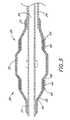
- Figure 3is a partial cross-sectional view of a preferred embodiment of the variable diameter inflation catheter at a second inflation profile.
- Figure 4is a schematic view of the embodiment of Figure 1, shown in the first inflation configuration.
- variable diameter inflation catheter 10in accordance with the present invention.
- Catheters embodying additional features known in the vascular dilatation artsuch as implantable stents, drug delivery, perfusion and dilatation features, or any combination of these features, can be used in combination with the focal balloon of the present invention as will be readily apparent to one of skill in the art in view of the disclosure herein.
- the catheter 10generally comprises an elongate tubular body 12 extending between a proximal control end 14 and a distal functional end 16.
- the length of the tubular body 12depends upon the desired application. For example, lengths in the area of about 120 cm to about 140 cm are typical for use in percutaneous transluminal coronary angioplasty applications.
- the tubular body 12may be produced in accordance with any of a variety of known techniques for manufacturing balloon-tipped catheter bodies, such as by extrusion of appropriate biocompatible plastic materials.
- at least a portion or all of the length of tubular body 12may comprise a spring coil, solid walled hypodermic needle tubing, or braided reinforced wall, as is understood in the catheter and guide wire arts.
- tubular body 12in accordance with the present invention, is provided with a generally circular cross-sectional configuration having an external diameter within the range of from about 0,076 cm (0.03 inches) to about 0,165 cm (0.065 inches).
- the tubular body 12has an external diameter of about 0,107 cm [0.042 inches (3.2 f)] throughout most of its length.
- generally triangular or oval cross-sectional configurationscan also be used, as well as other non-circular configurations, depending upon the number of lumen extending through the catheter, the method of manufacture and the intended use.
- the tubular body 12In a catheter intended for peripheral vascular applications, the tubular body 12 will typically have an outside diameter within the range of from about 0,1 cm (0.039 inches) to about 0,165 cm (0.065 inches). In coronary vascular applications, the tubular body 12 will typically have an outside diameter within the range of from about 0,066 cm (0.026 inches) to about 0,114 cm (0.045 inches). Diameters outside of the preferred ranges may also be used, provided that the functional consequences of the diameter are acceptable for the intended purpose of the catheter. For example, the lower limit of the diameter for tubular body 12 in a given application will be a function of the number of fluid or other functional lumen, support structures and the like contained in the catheter, and the desired structural integrity.
- Tubular body 12must have sufficient structural integrity (e.g., "pushability") to permit the catheter to be advanced to distal arterial locations without buckling or undesirable bending of the tubular body 12.
- the ability of the body 12 to transmit torquemay also be desirable, such as in embodiments having a drug delivery capability on less than the entire circumference of the delivery balloon. Larger diameters generally have sufficient internal flow properties and structural integrity, but reduce perfusion in the artery in which the catheter is placed. Increased diameter catheter bodies also tend to exhibit reduced flexibility, which can be disadvantageous in applications requiring placement of the distal end of the catheter in a remote vascular location. In addition, lesions requiring treatment are sometimes located in particularly small diameter arteries, necessitating the lowest possible profile.
- the distal end 16 of catheter 10is provided with at least one inflation balloon 18 having a variable diameter.
- the proximal end 14 of catheter 10is provided with a manifold 20 having a plurality of access ports, as is known in the art.
- manifold 20is provided with a guide wire port 22 in an over the wire embodiment and a balloon inflation port 24. Additional access ports are provided as needed, depending upon the functional capabilities of the catheter 10.
- the balloon 18can also be mounted on a rapid exchange type catheter, in which the proximal guidewire port 22 would be unnecessary as is understood in the art.
- the proximal guidewire access portis positioned along the length of the tubular body 12, such as between about 4 and about 20 cm from the distal end of the catheter.
- the two-step inflation profile of the inflation balloon 18is illustrated.
- the balloon 18is illustrated at a first inflation profile, in which it exhibits a substantially cylindrical central working profile.
- the dimensions in Figure 2are exaggerated to illustrate a proximal segment 26 and a distal segment 28 which are axially separated by a central focal segment 30.
- the exterior of the balloon 18preferably exhibits a substantially smooth cylindrical working profile.
- the inflation balloon 18is illustrated at a second inflation profile.
- the proximal segment 26 and the distal segment 28 of the balloonare separated by the central focal segment 30 having a greater diameter.
- the configuration of Figure 2is achieved by inflating the balloon 18 to a first inflation pressure, while the configuration of Figure 3 is achieved by increasing the inflation pressure to a second, higher pressure as will be discussed below.
- variable diameter inflation catheter 10is provided with at least a guidewire lumen 32 extending all the way through the balloon 18, and an inflation lumen 34 extending into the proximal end of the balloon 18.
- an inner balloon 36is disposed coaxially within an outer balloon 38.
- a substantially nondistensible expansion limiting band 40is disposed in between the balloons 36 and 38 adjacent a proximal annular shoulder 42, to limit the radial expansion of the balloon 18.
- a distal expansion limiting band 44is disposed between the inner balloon 36 and outer balloon 38 adjacent a distal annular shoulder 46.
- Expansion limiting bands 40 and 44 or other inflation limiting structurescan be provided in any of a variety of ways which will be well-understood by one of skill in the art in view of the disclosure herein.
- the bands 40 and 44each comprise a tubular section of polyester, each having an axial length of about 5 mm, a diameter of about 2.5 mm and a wall thickness of about 0,007 mm (0.0003 inches).
- Other generally nondistensible materialssuch as nylon, polyimide, Kevlar fiber, cross-linked polyethylene, polyethylene terephthalate and others, may be utilized to accomplish the expansion-limiting effect.
- the expansion limiting characteristicscan be achieved by the addition of a structure that is discrete from the balloon, or by modifying the expansion properties of the balloon material itself.
- the ballooncan be provided with zones of differing wall thickness, or zones having different levels of cross linking as will be discussed.
- the bands 40 and 44must be of a sufficient thickness or structural integrity for the particular material used to substantially withstand inflation under the pressures normally utilized in the context of dilatation catheters. However, the bands 40 and 44 are preferably thin enough to provide a substantially smooth exterior surface of the balloon 18.
- the expansion-limiting bands 40 and 44are sandwiched between the inner balloon 36 and the outer balloon 38.
- the expansion-limiting bands 40 and 44 or other inflation limiting structuresmay be coated or mounted on the exterior surface of the balloon 18, the interior surface of the balloon 18 or within the wall of the balloon 18.
- Balloon 18can be provided with two or more layers as illustrated, or with only a single layer as will be discussed.
- the axial length of the bands 40 and 44can be varied widely depending upon the dimensions and the objectives of the catheter 10 as will be apparent to one of ordinary skill in the art. Further, the proximal band 40 and distal band 44 need not be of similar lengths. In general, however, some examples of dimensions which are useful in the coronary angioplasty dilatation environment are reproduced in Table 1 below, in which A represents the axial length of the balloon 18 between proximal shoulder 42 and distal shoulder 46, B represents the axial distance between distal shoulder 46 and transition point 48, and C represents the axial length of the central focal segment 30.
- Table 1are exemplary only, and the present invention can be accomplished using a wide variety of other dimensions as will be apparent to one of skill in the art.
- the catheter 10 illustrated in Figures 2 and 3can be manufactured in accordance with any of a variety of techniques which will be appreciated by one of ordinary skill in the art in view of the disclosure herein.
- particular materials and dimensionswill be used as an example only, and other dimensions and materials can be selected depending upon the desired characteristics of the finished product.
- a low density polyethylene extrusion stock tubehaving an inside diameter of about 0,045 cm (0.018 inches) and an outside diameter of about 0,109 cm (0.043 inches) is used for the inner and outer balloons 36, 38.
- the polyethylene stock tubingis cross-linked by exposure to an electron beam in accordance with techniques well known in the art.
- a test segment of the cross-linked stock tubingis free blown up to 3.0 mm in diameter. If the cross-linked stock tubing can be free blown to a diameter greater then 3.0 mm, the stock tubing is cross-linked again and retested until the desired free blow diameter is achieved.
- the appropriately cross-linked stock tubingis then blown to a diameter of 2.5 mm within a teflon capture tube (not shown) which acts to mold the balloon to its desired first inflation diameter.
- the teflon capture tubeis a generally tubular body which has approximately the same inside diameter as the desired inflation diameter of the balloon.
- the teflon capture tubeis heated by any of a number of heating means such as electric coils or a furnace to a temperature which is sufficient to mold the balloon to the desired inflation diameter.
- the cross-linked polyethylene balloonis preferably heated to a temperature of about 148°C (300° F).
- the teflon chamberis then cooled to a temperature below the softening temperature of the balloon. Once cooled, the balloon is deflated and removed from the capture tube.
- a section of inflation balloon materialis thereafter stretched with application of heat to neck down the proximal and distal ends 37, 39 to a thickness of about 0.025 mm (0.001 inches) and a diameter which relatively closely fits the portion of the tubular catheter body 12 to which it is to be sealed.
- the balloonis then attached to the tubular body 12 by any of a variety of bonding techniques known to one of skill in the art such as solvent bonding, thermal adhesive bonding or by heat shrinking/sealing.
- bonding techniquesknown to one of skill in the art such as solvent bonding, thermal adhesive bonding or by heat shrinking/sealing.
- the choice of bonding techniquesis dependent on the type of balloon material and tubular body material used to form the catheter 10.
- inner balloon 36 and outer balloon 38are attached to the catheter body 10.
- the proximal necked end 37 of the inner balloon 36is heat sealed around the catheter body 12.
- the distal necked end 39 of the inner balloon 36is thereafter heat sealed around the distal end 16 of the catheter body 12.
- the length of the proximal end 37 and the distal end 39 of the inner balloon 36 which is secured to the catheter body 12is within the range of from about 3 mm to about 10 mm, however the proximal and distal balloon necked ends 37, 39 are as long as necessary to accomplish their functions as a proximal and distal seal.
- Expansion limiting bands 40 and 44are respectively positioned at the proximal segment 26 and the distal segment 28 of the inner balloon 36 and may be bonded or otherwise secured to the inner balloon 36.
- the outer balloon 38is thereafter be mounted to the catheter body 12 in a similar manner as the inner balloon 36, following "necking down" of the proximal and distal axial ends of the outer balloon 38 by axial stretching under the application of heat.
- the outer balloon 38is advanced axially over the inner balloon 36 and the expansion limiting bands 40 and 44.
- the outer balloon 38may thereafter be bonded to the inner balloon 36, and to the expansion limiting bands 40 and 44 by any of a variety of bonding techniques such as solvent bonding, thermal adhesive bonding or by heat sealing also depending on the type of balloon material used.
- the expansion limiting bandsare simply entrapped between the balloons without any bonding or adhesion.
- the inner balloon and the outer balloon 36, 38are both cross-linked polyethylene balloons which are difficult to bond together using conventional solvents. If sealing is desired, the inner balloon 38 and the outer balloon 38 are heat sealed together as described below. In another embodiment, the inner balloon 36 and outer balloon 38 are secured together through the use of a UV-curable adhesive.
- the inner balloon 36 and the outer balloon 38can be heat sealed together in a heating chamber (not shown) such as a Teflon capture tube.
- Inner balloon 36 and outer balloon 38are inflated in the chamber until the inner balloon and the outer balloon inflate to the first inflation diameter.
- the heating chamberis heated by any of a number of heating means such as electric coils or a furnace to heat air to a temperature which is sufficient to bond the two balloons 36, 38 together.
- the cross-linked polyethylene balloonsare preferably heated to a temperature of about 148°C (300° F) within the chamber which causes both balloons 36, 38 to seal together to form a double walled variable diameter inflation balloon 18.
- the chamberis then cooled to a temperature below the softening temperature of the inner and outer balloons 36 and 38. Once cooled, the variable diameter balloon 18 is deflated and the catheter 10 is removed from the chamber.
- variable diameter balloon design of the present inventioncan also be accomplished with a single layer balloon or a double layer balloon without the inclusion of additional expansion limiting bands. This is accomplished by decreasing the relative compliance of the zones of the balloon that are intended to remain at the first inflated diameter.
- polyethylene extrusion stockis cross-linked to 3.0 mm and blown into a mold of a diameter of about 2.5 mm as described above to form a balloon.
- the balloonis attached to the catheter as described above.
- the balloonis inflated and the central focal segment 30 of the balloon on the catheter 10 is masked such as with a steel clamp or other mask known in the art to block electron beam penetration, leaving the proximal segment 26 and the distal segment 28 of the balloon exposed.
- the inflated proximal segment 26 and distal segment 28 of the balloon 18are exposed again to an electron beam source to further cross-link the segments 26, 28 at the 2.5 mm diameter.
- Balloons manufactured in this mannerhave been found to exhibit a relatively highly compliant central zone and relatively less complaint axial end zones in a manner that achieves the two-step dilatation as illustrated in Figs. 2 and 3.
- a dual balloon structurewhich incorporates the expansion limiting bands as illustrated in Figs. 2 and 3.
- Balloons 18 made in accordance with the design illustrated in Figs. 2 and 3have been found to exhibit the inflation pressure profile illustrated in Table 2.
- the inflation pressure profile of the variable diameter inflation balloon 18 illustrated in Table 2provides an example of the manner in which a balloon 18 made in accordance with the foregoing method is inflated with the application of increased pressure.
- the central segment 30 and the proximal and distal segments 26, 28 of the balloon 18inflate together as the pressure increases.
- the pressurereaches 6 bar (atm)
- the diameter of the proximal and distal segments 26, 28 and the central segment 30 of the balloonall remain at about 2.5 mm.
- the diameter of the central segment 30 of the balloon 18has grown to about 3 mm while the proximal and distal segments 26, 28 remained inflated to the first diameter of 2.5 mm.
- the diameter of the central section 30 of the balloon 18will continue to increase until the burst pressure of the balloon 18 is reached.
- the burst pressurewas approximately 16 bar (atm) at normal body temperature.
- first inflation diameter and the second inflation diametercan also be varied depending upon the desired catheter characteristics as will be understood by one of ordinary skill in the art.
- a first inflated diameter of the catheter for coronary angioplasty applicationsis approximately 2.5 mm. Upon an increase of pressure, this diameter grows to a second inflated diameter of approximately 3 mm in the central focal segment 30.
- balloonscan be readily constructed having a difference between the first inflation diameter and second inflation diameter anywhere within the range of from about 0.1 mm up to 1.0 mm or more, depending upon the elastic limits of the material from which the balloon was constructed.
- coronary angioplasty dilatation balloonswill have a first diameter within the range of from about 1.5 mm to about 4.0 mm.
- Typical balloons for use in peripheral vascular applicationswill have a first inflation diameter within the range of from about 2 mm to about 10 mm.
- variable diameter balloon 18made in accordance with the foregoing designs has been found to benefit certain conventional percutaneous transluminal coronary angioplasty (PTCA) procedures.
- PTCApercutaneous transluminal coronary angioplasty
- the variable diameter balloon 18is percutaneously advanced and positioned such that the central segment 30 of the balloon 18 is adjacent a vascular treatment site.
- the treatment siteis a stenosis such as due to a plaque or thrombus.
- the variable diameter balloon 18is inflated to a first inflation profile to begin dilation of the stenosis.
- the first inflation profileis achieved by applying up to about 6 bar (atm) of pressure to the balloon 18.
- variable diameter balloon 18is inflated to a first inflation diameter, of about 2.5 mm, at an inflation pressure of 6 bar (atm).
- the first inflation diameteris preferably about the native diameter of the vessel.
- a second inflation profileis achieved wherein the central segment 30 of the balloon 18 expands beyond the diameter of the first inflation profile to a second inflation diameter, while the proximal segment 26 and the distal segment 28 remain at the first inflation diameter.
- the diameter of the central segment 30 of the balloon 18extends past the native diameter of the vessel to the second inflation diameter. Utilizing this method, and depending upon the balloon size selected, the stenosis is compressed to a point which is beyond the native diameter of the vessel.
- the diameter of the central segment 30 of the balloon 18 at the second inflation diameteris 3 mm and the diameter of the proximal end 26 and the distal end 28 at the first inflation diameter is 2.5 mm.
- Second inflation diameters in between the first inflation diameter and the maximum inflation diametercan be readily achieved by controlling inflation pressure, as illustrated for one embodiment in Table 2, above.
- the balloonis evacuated and the catheter withdrawn.
- the pressureis reduced until the balloon 18 resumes the first inflation profile.
- the balloon 18may be held at the first inflation diameter for short periods to continue to maintain patency of the lumen if short term rebound is a concern.
- This post dilatation stepis preferably accomplished using a catheter having perfusion capabilities.
- the remaining pressure applied to the balloon 18is reduced causing the variable diameter balloon 18 to deflate.
- the catheteris then extracted from the vessel utilizing conventional PTCA procedures.
- Tubular stents of the type adapted to be carried to a vascular site on a balloon catheter, and for expansion from a first insertion diameter to a second implanted diameterare well-known in the art.
- an expandable stentis positioned about the deflated balloon of a variable diameter balloon catheter in accordance with the present invention.
- the balloonis thereafter percutaneously inserted into the vascular system and transluminally advanced to position the stent at the treatment site.
- the balloonis thereafter inflated to at least a first inflation configuration, wherein the balloon exhibits a substantially cylindrical profile throughout its axial length.
- the balloonis optionally inflated to a second inflation profile, thereby inflating at least a portion of the stent to a second, greater diameter.
- the central region of the stentmay preferably be inflated to a larger diameter than either of the axial ends of the stent.
- the axial length of the stentis selected to approximately equal the axial length of the focal zone on the inflation balloon.
- the inflation balloon within the stentis expandable to a diameter slightly larger than the native diameter of the adjacent vessel. This permits subsequent overgrowth of endothelium along the interior wall of the stent while still leaving a lumen having an interior diameter within the stent approximately equal to the native diameter of the lumen adjacent the stent.
- variable diameter balloonis utilized to "tack down" a previously positioned tubular stent.
- a tubular stentis identified within a body lumen.
- the focal balloonis positioned within the stent in accordance with conventional PTCA procedures, and the balloon is inflated so that the central, focal section enlarges the diameter of at least a first portion of the stent.
- the balloonis thereafter reduced in diameter, and, preferably, repositioned within a second region within the stent and then reinflated to expand at least the second region of the stent. Expansions of this type can be repeated until the stent has been expanded as desired.
- the balloonis thereafter evacuated and removed from the patient.
- a further aspectis a method of percutaneous transluminal angioplasty in which multiple lesions of differing sizes are dilated without removing the catheter from the body.
- the variable diameter balloonis positioned within a first stenosis in accordance with conventional PTCA techniques.
- the balloonis dilated to a sufficient diameter to restore patency to the vascular lumen.
- the balloonis thereafter deflated, and repositioned within a second stenosis in the vascular system.
- the balloonis inflated to restore patency of the vessel in the region of the second stenosis.
- the balloonmay be deflated, and repositioned within a third stenosis in the body lumen.
- the balloonis then inflated to a sufficient diameter to restore patency in the body lumen in the region of the third stenosis.
- Four or more lesionscan be treated seriatim in this manner.
- the balloonis inflated to a first diameter in the first stenosis, and to a second, different diameter, in the second stenosis.
- This methodis accomplished by supplying a first inflation pressure to the balloon while the balloon is positioned in a first position in the vascular system, and thereafter supplying a second pressure to the balloon when the balloon is in a second position in the vascular system.
- each of the first and second inflation pressuresis selected to achieve a preselected inflation diameter of the balloon.
Landscapes
- Health & Medical Sciences (AREA)
- Heart & Thoracic Surgery (AREA)
- Life Sciences & Earth Sciences (AREA)
- Engineering & Computer Science (AREA)
- Biomedical Technology (AREA)
- Pulmonology (AREA)
- Biophysics (AREA)
- Anesthesiology (AREA)
- Child & Adolescent Psychology (AREA)
- Hematology (AREA)
- Animal Behavior & Ethology (AREA)
- General Health & Medical Sciences (AREA)
- Public Health (AREA)
- Veterinary Medicine (AREA)
- Manufacturing & Machinery (AREA)
- Media Introduction/Drainage Providing Device (AREA)
Description
- The present invention relates to catheters for insertioninto a body lumen. More particularly, the present inventionrelates to a "focal" balloon dilatation catheter for use inthe vascular system.
- Prior art vascular dilatation balloons on typicaldilatation catheters tend to fall into one of two broadclasses. Most are considered noncompliant balloons, formedfrom a generally nondistensible material such as polyethylene.The perceived advantage of the noncompliant balloons is thatthey exhibit a substantially uniform exterior inflated profilewhich remains substantially unchanged upon incrementalincreases in inflation pressure. In theory, noncompliantballoons are advantageous because they allow the introductionof increased inflation pressure to break particularlycalcified lesions, yet retain a predictable inflated profileso that damage to the surrounding native lumen is minimized.
- Certain compliant balloons are also known in the art. Acompliant balloon is one which is able to grow in diameter inresponse to increased inflation pressure. One difficulty withcompliant balloons, however, is that inflation within adifficult lesion can cause the balloon to inflate around theplaque to produce a generally hourglass-shaped inflatedprofile. This can result in damage to the native vesseladjacent the obstruction, while at the same time failing tosufficiently alleviate the stenosis.
- Therefore, there exists a need in the art for a vasculardilatation catheter with a balloon which is able to grow indiameter in response to increased inflation pressure, andwhich expands in a predictable inflation profile whileminimizing any damage to the native vessel.
- Documents WO 89/02763 and EP-A-0 347 023disclose balloon catheters wherein two segments ofthe balloon are inflatable to two different diameters.
- There is provided in accordance with one aspect of thepresent invention a balloon catheter, such as for performingballoon dilatation procedures in a body lumen. The cathetercomprises an elongate flexible tubular body, and an inflatable balloon on the tubular body. The balloon is inflatable to afirst diameter, and at least one portion of the balloon isinflatable to a second, larger diameter.A proximal end and a distal end of the balloon are inflatableto a first diameter and a central segment of the balloon isinflatable to both the first diameter and also to a secondgreater diameter. Preferably, inflation to the first diameteris achieved by inflation to a first pressure, and inflation tothe second diameter is achieved by inflation to a second,higher pressure. In one embodiment, the catheter comprisesproximal and distal expansion limiting bands positioned on theproximal end and distal end of the inflation balloon to limitexpansion of the proximal end and the distal end of theinflation balloon at the first diameter.
- The catheter is used to treat a site in abody lumen.Theproximal segment and the distal segment of the balloon areinflatable to a first diameter and the central segment of theballoon is inflatable to a second greater diameter. Thecatheter is positioned within a body lumen so that the balloonis adjacent a treatment site. The balloon is inflated to afirst inflation profile, wherein the proximal segment, thedistal segment and the central segment are inflated to thefirst inflation diameter, to treat the site. The balloon isthereafter inflated to a second inflation profile, wherein theproximal segment and the distal segment are inflated to thefirst inflation diameter and the central segment is inflatedto the second inflation diameter, to further treat the site.
- Further features and advantages of the present inventionwill become apparent to one of skill in the art in view of theDetailed Description of Preferred Embodiments which follows,when considered together with the attached drawings andclaims.
- Figure 1 is a schematic view of a preferred embodiment ofa variable diameter inflation catheter of thepresent invention, in the second inflation configuration.
- Figure 2 is a partial cross-sectional view of a preferredembodiment of the variable diameter inflation catheter at afirst inflation profile.
- Figure 3 is a partial cross-sectional view of a preferredembodiment of the variable diameter inflation catheter at asecond inflation profile.
- Figure 4 is a schematic view of the embodiment of Figure1, shown in the first inflation configuration.
- Referring to Figure 1, there is disclosed a variable
diameter inflation catheter 10 in accordance withthe present invention. Catheters embodyingadditional features known in the vascular dilatation art, suchas implantable stents, drug delivery, perfusion and dilatationfeatures, or any combination of these features, can be used incombination with the focal balloon of the present invention aswill be readily apparent to one of skill in the art in view ofthe disclosure herein. - The
catheter 10 generally comprises an elongatetubularbody 12 extending between aproximal control end 14 and adistalfunctional end 16. The length of thetubular body 12depends upon the desired application. For example, lengths inthe area of about 120 cm to about 140 cm are typical for usein percutaneous transluminal coronary angioplastyapplications. - The
tubular body 12 may be produced in accordance withany of a variety of known techniques for manufacturingballoon-tipped catheter bodies, such as by extrusion ofappropriate biocompatible plastic materials. Alternatively,at least a portion or all of the length oftubular body 12 maycomprise a spring coil, solid walled hypodermic needle tubing,or braided reinforced wall, as is understood in the catheterand guide wire arts. - In general,
tubular body 12, in accordance with thepresent invention, is provided with a generally circularcross-sectional configuration having an external diameterwithin the range of from about 0,076 cm (0.03 inches) to about 0,165 cm (0.065inches). In accordance with one preferred embodiment of theinvention, thetubular body 12 has an external diameter ofabout 0,107 cm [0.042 inches (3.2 f)] throughout most of its length.Alternatively, generally triangular or oval cross-sectionalconfigurations can also be used, as well as other non-circularconfigurations, depending upon the number of lumen extendingthrough the catheter, the method of manufacture and theintended use. - In a catheter intended for peripheral vascularapplications, the
tubular body 12 will typically have anoutside diameter within the range of from about 0,1 cm (0.039 inches)to about 0,165 cm (0.065 inches). In coronary vascular applications, thetubular body 12 will typically have an outside diameter withinthe range of from about 0,066 cm (0.026 inches) to about 0,114 cm (0.045 inches).Diameters outside of the preferred ranges may also be used,provided that the functional consequences of the diameter areacceptable for the intended purpose of the catheter. Forexample, the lower limit of the diameter fortubular body 12in a given application will be a function of the number offluid or other functional lumen, support structures and thelike contained in the catheter, and the desired structuralintegrity. Tubular body 12 must have sufficient structural integrity(e.g., "pushability") to permit the catheter to be advanced todistal arterial locations without buckling or undesirablebending of thetubular body 12. The ability of thebody 12 totransmit torque may also be desirable, such as in embodimentshaving a drug delivery capability on less than the entirecircumference of the delivery balloon. Larger diametersgenerally have sufficient internal flow properties andstructural integrity, but reduce perfusion in the artery inwhich the catheter is placed. Increased diameter catheterbodies also tend to exhibit reduced flexibility, which can be disadvantageous in applications requiring placement of thedistal end of the catheter in a remote vascular location. Inaddition, lesions requiring treatment are sometimes located inparticularly small diameter arteries, necessitating the lowestpossible profile.- As illustrated schematically in Figure 1, the
distal end 16 ofcatheter 10 is provided with at least oneinflationballoon 18 having a variable diameter. Theproximal end 14 ofcatheter 10 is provided with amanifold 20 having a pluralityof access ports, as is known in the art. Generally,manifold 20 is provided with aguide wire port 22 in an over the wireembodiment and aballoon inflation port 24. Additional accessports are provided as needed, depending upon the functionalcapabilities of thecatheter 10. Theballoon 18 can also bemounted on a rapid exchange type catheter, in which theproximal guidewire port 22 would be unnecessary as isunderstood in the art. In a rapid exchange embodiment, theproximal guidewire access port is positioned along the lengthof thetubular body 12, such as between about 4 and about 20cm from the distal end of the catheter. - Referring to Figures 2 and 3, the two-step inflationprofile of the
inflation balloon 18 is illustrated. In Figure2, theballoon 18 is illustrated at a first inflation profile,in which it exhibits a substantially cylindrical centralworking profile. The dimensions in Figure 2 are exaggeratedto illustrate aproximal segment 26 and adistal segment 28which are axially separated by a centralfocal segment 30.However, as will be understood by one of ordinary skill in theart, when theballoon 18 is inflated to the first inflationprofile, the exterior of theballoon 18 preferably exhibits asubstantially smooth cylindrical working profile. - In Figure 3, the
inflation balloon 18 is illustrated ata second inflation profile. Theproximal segment 26 and thedistal segment 28 of the balloon are separated by the centralfocal segment 30 having a greater diameter. The configurationof Figure 2 is achieved by inflating theballoon 18 to a firstinflation pressure, while the configuration of Figure 3 is achieved by increasing the inflation pressure to a second,higher pressure as will be discussed below. - The details of one preferred embodiment of the variable
diameter inflation catheter 10 are discussed with reference toFigures 2 and 3. Preferably, thetubular body 12 is providedwith at least aguidewire lumen 32 extending all the waythrough theballoon 18, and aninflation lumen 34 extendinginto the proximal end of theballoon 18. - In the illustrated embodiment, an
inner balloon 36 isdisposed coaxially within anouter balloon 38. Asubstantially nondistensibleexpansion limiting band 40 isdisposed in between theballoons annular shoulder 42, to limit the radial expansion of theballoon 18. Similarly, a distalexpansion limiting band 44 isdisposed between theinner balloon 36 andouter balloon 38adjacent a distalannular shoulder 46. Expansion limiting bands bands - The expansion limiting characteristics can be achieved bythe addition of a structure that is discrete from the balloon,or by modifying the expansion properties of the balloonmaterial itself. For example, the balloon can be providedwith zones of differing wall thickness, or zones havingdifferent levels of cross linking as will be discussed.
- In general, the
bands bands balloon 18. - Preferably, as illustrated in Figures 2 and 3, theexpansion-limiting
bands inner balloon 36 and theouter balloon 38. In alternativeembodiments, the expansion-limitingbands balloon 18, the interior surface oftheballoon 18 or within the wall of theballoon 18.Balloon 18 can be provided with two or more layers as illustrated, orwith only a single layer as will be discussed. - The axial length of the
bands catheter 10 as will be apparent to one of ordinary skill inthe art. Further, theproximal band 40 anddistal band 44need not be of similar lengths. In general, however, someexamples of dimensions which are useful in the coronaryangioplasty dilatation environment are reproduced in Table 1below, in which A represents the axial length of theballoon 18 betweenproximal shoulder 42 anddistal shoulder 46, Brepresents the axial distance betweendistal shoulder 46 andtransition point 48, and C represents the axial length of thecentralfocal segment 30. The dimensions of Table 1 areexemplary only, and the present invention can be accomplishedusing a wide variety of other dimensions as will be apparentto one of skill in the art.A B C 20 mm 5 mm 10 mm 30 mm 5 mm 20 mm 40 mm 5-10 mm 20-30 mm - The
catheter 10 illustrated in Figures 2 and 3 can bemanufactured in accordance with any of a variety of techniqueswhich will be appreciated by one of ordinary skill in the artin view of the disclosure herein. In the followingdisclosure, particular materials and dimensions will be usedas an example only, and other dimensions and materials can beselected depending upon the desired characteristics of thefinished product. - In one particular method of manufacturing, a low densitypolyethylene extrusion stock tube having an inside diameter ofabout 0,045 cm (0.018 inches) and an outside diameter of about 0,109 cm (0.043inches) is used for the inner and
outer balloons - The polyethylene stock tubing is cross-linked by exposureto an electron beam in accordance with techniques well knownin the art. A test segment of the cross-linked stock tubingis free blown up to 3.0 mm in diameter. If the cross-linkedstock tubing can be free blown to a diameter greater then 3.0mm, the stock tubing is cross-linked again and retested untilthe desired free blow diameter is achieved.
- The appropriately cross-linked stock tubing is then blownto a diameter of 2.5 mm within a teflon capture tube (notshown) which acts to mold the balloon to its desired firstinflation diameter. The teflon capture tube is a generallytubular body which has approximately the same inside diameteras the desired inflation diameter of the balloon. The tefloncapture tube is heated by any of a number of heating meanssuch as electric coils or a furnace to a temperature which issufficient to mold the balloon to the desired inflationdiameter. In this case, the cross-linked polyethylene balloonis preferably heated to a temperature of about 148°C (300° F). Theteflon chamber is then cooled to a temperature below thesoftening temperature of the balloon. Once cooled, theballoon is deflated and removed from the capture tube.
- A section of inflation balloon material is thereafterstretched with application of heat to neck down the proximaland distal ends 37, 39 to a thickness of about 0.025 mm (0.001 inches)and a diameter which relatively closely fits the portion of the
tubular catheter body 12 to which it is to be sealed. - The balloon is then attached to the
tubular body 12 byany of a variety of bonding techniques known to one of skillin the art such as solvent bonding, thermal adhesive bondingor by heat shrinking/sealing. The choice of bondingtechniques is dependent on the type of balloon material andtubular body material used to form thecatheter 10. - In one particular method of manufacture,
inner balloon 36andouter balloon 38 are attached to thecatheter body 10.The proximalnecked end 37 of theinner balloon 36 is heatsealed around thecatheter body 12. The distalnecked end 39of theinner balloon 36 is thereafter heat sealed around thedistal end 16 of thecatheter body 12. In general, the lengthof theproximal end 37 and thedistal end 39 of theinnerballoon 36 which is secured to thecatheter body 12 is withinthe range of from about 3 mm to about 10 mm, however theproximal and distal balloon necked ends 37, 39 are as long asnecessary to accomplish their functions as a proximal anddistal seal. Expansion limiting bands proximal segment 26 and thedistal segment 28 of theinner balloon 36 and may be bonded or otherwisesecured to theinner balloon 36. Theouter balloon 38 isthereafter be mounted to thecatheter body 12 in a similarmanner as theinner balloon 36, following "necking down" ofthe proximal and distal axial ends of theouter balloon 38 byaxial stretching under the application of heat. Theouterballoon 38 is advanced axially over theinner balloon 36 andtheexpansion limiting bands outer balloon 38may thereafter be bonded to theinner balloon 36, and to theexpansion limiting bands - In a preferred embodiment, the inner balloon and the
outer balloon innerballoon 38 and theouter balloon 38 are heat sealed togetheras described below. In another embodiment, theinner balloon 36 andouter balloon 38 are secured together through the useof a UV-curable adhesive. - The
inner balloon 36 and theouter balloon 38, oncemounted to thecatheter body 12, can be heat sealed togetherin a heating chamber (not shown) such as a Teflon capturetube.Inner balloon 36 andouter balloon 38 are inflated inthe chamber until the inner balloon and the outer ballooninflate to the first inflation diameter. The heating chamberis heated by any of a number of heating means such as electriccoils or a furnace to heat air to a temperature which issufficient to bond the twoballoons balloons diameter inflation balloon 18. Thechamber is then cooled to a temperature below the softeningtemperature of the inner andouter balloons variable diameter balloon 18 is deflated and thecatheter 10 is removed from the chamber. - It will be apparent to one of skill in the art, that itis possible to attach the
inner balloon 36 and theouterballoon 38 to thecatheter body 12 without adhesively bondingor otherwise securing the two balloons together. In thiscase, the two balloons will respond to the applied inflationpressure with theinner balloon 36 forcing theouter balloon 38 to simultaneously inflate bothballoons expansion limiting bands inner balloon 36 and theouter balloon 38 and donot in this embodiment need to be bonded to either balloon. - The variable diameter balloon design of the presentinvention can also be accomplished with a single layer balloonor a double layer balloon without the inclusion of additional expansion limiting bands. This is accomplished by decreasingthe relative compliance of the zones of the balloon that areintended to remain at the first inflated diameter. Forexample, polyethylene extrusion stock is cross-linked to 3.0mm and blown into a mold of a diameter of about 2.5 mm asdescribed above to form a balloon. The balloon is attached tothe catheter as described above. The balloon is inflated andthe central
focal segment 30 of the balloon on thecatheter 10is masked such as with a steel clamp or other mask known inthe art to block electron beam penetration, leaving theproximal segment 26 and thedistal segment 28 of the balloonexposed. The inflatedproximal segment 26 anddistal segment 28 of theballoon 18 are exposed again to an electron beamsource to further cross-link thesegments - Preferably, however, a dual balloon structure is used,which incorporates the expansion limiting bands as illustratedin Figs. 2 and 3.
Balloons 18 made in accordance with thedesign illustrated in Figs. 2 and 3 have been found to exhibitthe inflation pressure profile illustrated in Table 2.PRESSURE
[bar]CENTRAL SEGMENT DIAMETER PROXIMAL AND DISTAL SEGMENT DIAMETER 6 (atm) 2.5 mm 2.5 mm 7 (atm) 2.6 mm 2.5 mm 8 (atm) 2.7 mm 2.5 mm 9 (atm) 2.8 mm 2.5 mm 10 (atm) 2.9 mm 2.5 mm 11 (atm) 3.0 mm 2.5 mm 12 (atm) 3.1 mm 2.5 mm 13 (atm) 3.2 mm 2.5 mm 14 (atm) 3.3 mm 2.6 mm - The inflation pressure profile of the variable
diameterinflation balloon 18 illustrated in Table 2 provides anexample of the manner in which aballoon 18 made in accordancewith the foregoing method is inflated with the application ofincreased pressure. Initially, thecentral segment 30 and theproximal anddistal segments balloon 18 inflatetogether as the pressure increases. When the pressure reaches6 bar (atm), for example, the diameter of the proximal anddistalsegments central segment 30 of the balloon allremain at about 2.5 mm. At 11 bar (atm), the diameter of thecentral segment 30 of theballoon 18 has grown to about 3 mmwhile the proximal anddistal segments central section 30 of theballoon 18 will continue to increaseuntil the burst pressure of theballoon 18 is reached. In oneprototype, the burst pressure was approximately 16 bar (atm) atnormal body temperature. - Both the first inflation diameter and the secondinflation diameter can also be varied depending upon the desired catheter characteristics as will be understood by oneof ordinary skill in the art. In a preferred embodiment, afirst inflated diameter of the catheter for coronaryangioplasty applications is approximately 2.5 mm. Upon anincrease of pressure, this diameter grows to a second inflateddiameter of approximately 3 mm in the central
focal segment 30. In general, balloons can be readily constructed having adifference between the first inflation diameter and secondinflation diameter anywhere within the range of from about 0.1mm up to 1.0 mm or more, depending upon the elastic limits ofthe material from which the balloon was constructed.Typically, coronary angioplasty dilatation balloons will havea first diameter within the range of from about 1.5 mm toabout 4.0 mm. Typical balloons for use in peripheral vascularapplications will have a first inflation diameter within therange of from about 2 mm to about 10 mm. - A
variable diameter balloon 18 made in accordance withthe foregoing designs has been found to benefit certain conventional percutaneous transluminal coronary angioplasty(PTCA) procedures. In accordance with a method of use of thepresent invention, thevariable diameter balloon 18 ispercutaneously advanced and positioned such that thecentralsegment 30 of theballoon 18 is adjacent a vascular treatmentsite. Generally, the treatment site is a stenosis such as dueto a plaque or thrombus. Thevariable diameter balloon 18 isinflated to a first inflation profile to begin dilation of thestenosis. Preferably, the first inflation profile is achievedby applying up to about 6 bar (atm) of pressure to theballoon 18.At the first inflation profile, the entire balloon is inflatedto the inner diameter of the vessel, thus restoring patency tothe vascular lumen. In one embodiment, thevariable diameterballoon 18 is inflated to a first inflation diameter, of about2.5 mm, at an inflation pressure of 6 bar (atm). The firstinflation diameter is preferably about the native diameter ofthe vessel. - As additional pressure is applied to the
variablediameter balloon 18, a second inflation profile is achievedwherein thecentral segment 30 of theballoon 18 expandsbeyond the diameter of the first inflation profile to a secondinflation diameter, while theproximal segment 26 and thedistal segment 28 remain at the first inflation diameter. Asthe pressure applied to thevariable diameter balloon 18increases, the diameter of thecentral segment 30 of theballoon 18 extends past the native diameter of the vessel tothe second inflation diameter. Utilizing this method, anddepending upon the balloon size selected, the stenosis iscompressed to a point which is beyond the native diameter ofthe vessel. In a preferred embodiment, at an applied pressureof 11 bar (atm) the diameter of thecentral segment 30 of theballoon 18 at the second inflation diameter is 3 mm and thediameter of theproximal end 26 and thedistal end 28 at thefirst inflation diameter is 2.5 mm. Second inflationdiameters in between the first inflation diameter and themaximum inflation diameter can be readily achieved bycontrolling inflation pressure, as illustrated for one embodiment in Table 2, above. - After the stenosis is compressed to or beyond the nativediameter of the vessel, the balloon is evacuated and thecatheter withdrawn. Alternatively, if desired, the pressureis reduced until the
balloon 18 resumes the first inflationprofile. At this point, theballoon 18 may be held at thefirst inflation diameter for short periods to continue tomaintain patency of the lumen if short term rebound is aconcern. This post dilatation step is preferably accomplishedusing a catheter having perfusion capabilities. Finally, theremaining pressure applied to theballoon 18 is reducedcausing thevariable diameter balloon 18 to deflate. Thecatheter is then extracted from the vessel utilizingconventional PTCA procedures. - Tubular stents of the type adaptedto be carried to a vascular site on a balloon catheter, andfor expansion from a first insertion diameter to a secondimplanted diameter are well-known in the art.
- In accordance with a method of implanting a tubularstent, an expandable stent is positioned about the deflatedballoon of a variable diameter balloon catheter in accordancewith the present invention. The balloon is thereafterpercutaneously inserted into the vascular system andtransluminally advanced to position the stent at the treatmentsite. The balloon is thereafter inflated to at least a firstinflation configuration, wherein the balloon exhibits asubstantially cylindrical profile throughout its axial length.Thereafter, the balloon is optionally inflated to a secondinflation profile, thereby inflating at least a portion of thestent to a second, greater diameter. Depending upon theetiology of the underlying condition, the central region ofthe stent may preferably be inflated to a larger diameter thaneither of the axial ends of the stent. Alternatively,the axial length of the stent is selected to approximatelyequal the axial length of the focal zone on the inflation balloon. In this manner, the inflation balloon within thestent is expandable to a diameter slightly larger than thenative diameter of the adjacent vessel. This permitssubsequent overgrowth of endothelium along the interior wallof the stent while still leaving a lumen having an interiordiameter within the stent approximately equal to the nativediameter of the lumen adjacent the stent.
- The variable diameter balloon is utilized to "tackdown" a previously positioned tubular stent.A tubular stent isidentified within a body lumen. The focal balloon ispositioned within the stent in accordance with conventionalPTCA procedures, and the balloon is inflated so that thecentral, focal section enlarges the diameter of at least afirst portion of the stent. The balloon is thereafter reducedin diameter, and, preferably, repositioned within a secondregion within the stent and then reinflated to expand at leastthe second region of the stent. Expansions of this type canbe repeated until the stent has been expanded as desired. Theballoon is thereafter evacuated and removed from the patient.
- A further aspectis a method of percutaneoustransluminal angioplasty in which multiple lesions ofdiffering sizes are dilated without removing the catheter fromthe body.The variable diameter balloon is positioned withina first stenosis in accordance with conventional PTCAtechniques. The balloon is dilated to a sufficient diameterto restore patency to the vascular lumen. The balloon isthereafter deflated, and repositioned within a second stenosisin the vascular system. The balloon is inflated to restorepatency of the vessel in the region of the second stenosis.Optionally, the balloon may be deflated, and repositionedwithin a third stenosis in the body lumen. The balloon isthen inflated to a sufficient diameter to restore patency inthe body lumen in the region of the third stenosis. Four or more lesions can be treated seriatim in this manner.
- Preferably, the balloon is inflated to a first diameterin the first stenosis, and to a second, different diameter, inthe second stenosis. In this manner, multiple dilatations atdifferent diameters can be accomplished utilizing the balloonof the present invention. This method is accomplished bysupplying a first inflation pressure to the balloon while theballoon is positioned in a first position in the vascularsystem, and thereafter supplying a second pressure to theballoon when the balloon is in a second position in thevascular system. In accordance with the previous disclosureherein, each of the first and second inflation pressures isselected to achieve a preselected inflation diameter of theballoon.
Claims (3)
- A balloon catheter (10) comprising an elongate, flexibletubular body (12) and an inflatable balloon (18) on thetubular body (12),
characterized in that
the balloon (18) includes a proximal segment (26) near aproximal end of the balloon (18), a central segment (30),and a distal segment (28) near a distal end of the balloon(18), wherein the proximal and distal segments (26, 28) areinflatable to a first diameter and the central segment (30)is inflatable to a second, greater diameter. - The balloon catheter (10) of Claim 1, further comprisingproximal and distal expansion limiting bands (40, 44)positioned on said proximal and distal segments (26, 28) ofsaid inflatable balloon (18) to limit inflation of saidproximal and said distal segments (26, 28) of the inflationballoon (18) at said first diameter.
- The balloon catheter (10) of Claims 1 or 2, wherein thefirst inflated diameter is within the range of fromabout 1.5 mm to about 10 mm.
Applications Claiming Priority (2)
| Application Number | Priority Date | Filing Date | Title |
|---|---|---|---|
| US08/201,935US5470313A (en) | 1994-02-24 | 1994-02-24 | Variable diameter balloon dilatation catheter |
| US201935 | 1994-02-24 |
Publications (2)
| Publication Number | Publication Date |
|---|---|
| EP0669143A1 EP0669143A1 (en) | 1995-08-30 |
| EP0669143B1true EP0669143B1 (en) | 2003-03-12 |
Family
ID=22747894
Family Applications (1)
| Application Number | Title | Priority Date | Filing Date |
|---|---|---|---|
| EP94119841AExpired - LifetimeEP0669143B1 (en) | 1994-02-24 | 1994-12-15 | Variable diameter balloon dilatation catheter |
Country Status (4)
| Country | Link |
|---|---|
| US (1) | US5470313A (en) |
| EP (1) | EP0669143B1 (en) |
| JP (1) | JP2859150B2 (en) |
| DE (1) | DE69432247T2 (en) |
Cited By (2)
| Publication number | Priority date | Publication date | Assignee | Title |
|---|---|---|---|---|
| US8206372B2 (en) | 1997-10-15 | 2012-06-26 | Boston Scientific Scimed, Inc. | Catheter with spiral cut transition member |
| US12171962B2 (en) | 2015-07-13 | 2024-12-24 | Biotronik Ag | Mechanically actuated and functionally integratable catheter system for treating vascular and non-vascular diseases and related methods |
Families Citing this family (143)
| Publication number | Priority date | Publication date | Assignee | Title |
|---|---|---|---|---|
| US5415635A (en)* | 1992-07-21 | 1995-05-16 | Advanced Cardiovascular Systems, Inc. | Balloon assembly with separately inflatable sections |
| US6120523A (en) | 1994-02-24 | 2000-09-19 | Radiance Medical Systems, Inc. | Focalized intraluminal balloons |
| US6027486A (en)* | 1996-05-02 | 2000-02-22 | Radiance Medical Systems, Inc. | Interactive angioplasty |
| US5645560A (en)* | 1995-12-15 | 1997-07-08 | Cardiovascular Dynamics, Inc. | Fixed focal balloon for interactive angioplasty and stent implantation |
| US5843116A (en)* | 1996-05-02 | 1998-12-01 | Cardiovascular Dynamics, Inc. | Focalized intraluminal balloons |
| US5749851A (en)* | 1995-03-02 | 1998-05-12 | Scimed Life Systems, Inc. | Stent installation method using balloon catheter having stepped compliance curve |
| US5868704A (en)* | 1995-09-18 | 1999-02-09 | W. L. Gore & Associates, Inc. | Balloon catheter device |
| US5752934A (en)* | 1995-09-18 | 1998-05-19 | W. L. Gore & Associates, Inc. | Balloon catheter device |
| WO1997017099A1 (en)* | 1995-11-06 | 1997-05-15 | C.R. Bard, Inc. | Balloon catheter for drug application |
| ATE290832T1 (en) | 1996-01-05 | 2005-04-15 | Medtronic Inc | EXPANDABLE ENDOLUMINAL PROSTHESES |
| US6104833A (en)* | 1996-01-09 | 2000-08-15 | Fujitsu Limited | Pattern recognizing apparatus and method |
| US5697971A (en)* | 1996-06-11 | 1997-12-16 | Fischell; Robert E. | Multi-cell stent with cells having differing characteristics |
| US6391032B2 (en) | 1996-08-23 | 2002-05-21 | Scimed Life Systems, Inc. | Stent delivery system having stent securement means |
| JP3968444B2 (en)* | 1996-08-23 | 2007-08-29 | ボストン サイエンティフィック サイムド,インコーポレイテッド | Stent delivery mechanism with stent fixation device |
| US6007543A (en) | 1996-08-23 | 1999-12-28 | Scimed Life Systems, Inc. | Stent delivery system with stent securement means |
| US6077273A (en) | 1996-08-23 | 2000-06-20 | Scimed Life Systems, Inc. | Catheter support for stent delivery |
| US5944726A (en)* | 1996-08-23 | 1999-08-31 | Scimed Life Systems, Inc. | Stent delivery system having stent securement means |
| US6123712A (en) | 1996-08-23 | 2000-09-26 | Scimed Life Systems, Inc. | Balloon catheter with stent securement means |
| US6395008B1 (en) | 1996-08-23 | 2002-05-28 | Scimed Life Systems, Inc. | Stent delivery device using stent cups and mounting collars |
| US5980530A (en)* | 1996-08-23 | 1999-11-09 | Scimed Life Systems Inc | Stent delivery system |
| US5954740A (en)* | 1996-09-23 | 1999-09-21 | Boston Scientific Corporation | Catheter balloon having raised radial segments |
| US6293924B1 (en) | 1996-12-12 | 2001-09-25 | Advanced Cardiovascular Systems, Inc. | Balloon assembly with separately inflatable sections |
| JPH10179749A (en)* | 1996-12-24 | 1998-07-07 | Buaayu:Kk | Infusion catheter |
| US6261260B1 (en) | 1997-04-15 | 2001-07-17 | Terumo Kabushiki Kaisha | Balloon for medical tube and medical tube equipped with the same |
| US6776792B1 (en) | 1997-04-24 | 2004-08-17 | Advanced Cardiovascular Systems Inc. | Coated endovascular stent |
| US5868708A (en)* | 1997-05-07 | 1999-02-09 | Applied Medical Resources Corporation | Balloon catheter apparatus and method |
| WO1999016499A1 (en) | 1997-10-01 | 1999-04-08 | Boston Scientific Corporation | Dilation systems and related methods |
| US5961536A (en)* | 1997-10-14 | 1999-10-05 | Scimed Life Systems, Inc. | Catheter having a variable length balloon and method of using the same |
| US6013055A (en)* | 1997-11-13 | 2000-01-11 | Boston Scientific Corporation | Catheter balloon having selected folding characteristics |
| US6179827B1 (en) | 1998-03-16 | 2001-01-30 | Chase Medical | Catheter having integral expandable/collapsible lumen |
| US6440138B1 (en) | 1998-04-06 | 2002-08-27 | Kyphon Inc. | Structures and methods for creating cavities in interior body regions |
| US6287314B1 (en) | 1998-04-21 | 2001-09-11 | Advanced Cardiovascular Systems, Inc. | Stent deploying catheter system |
| US20010001113A1 (en) | 1998-04-21 | 2001-05-10 | Florencia Lim | Balloon catheter |
| US6193738B1 (en) | 1998-05-11 | 2001-02-27 | Scimed Life Systems, Inc. | Balloon cones and waists thinning methodology |
| US6024752A (en)* | 1998-05-11 | 2000-02-15 | Scimed Life Systems, Inc. | Soft flexible tipped balloon |
| US5997563A (en)* | 1998-09-28 | 1999-12-07 | Medtronic, Inc. | Implantable stent having variable diameter |
| US6017324A (en)* | 1998-10-20 | 2000-01-25 | Tu; Lily Chen | Dilatation catheter having a bifurcated balloon |
| US6123718A (en)* | 1998-11-02 | 2000-09-26 | Polymerex Medical Corp. | Balloon catheter |
| US6319244B2 (en) | 1999-03-16 | 2001-11-20 | Chase Medical, L.P. | Catheter with flexible and rigid reinforcements |
| US6258099B1 (en)* | 1999-03-31 | 2001-07-10 | Scimed Life Systems, Inc. | Stent security balloon/balloon catheter |
| US6200325B1 (en)* | 1999-03-31 | 2001-03-13 | Advanced Cardiovascular Systems, Inc. | Balloon catheter and stent deploying catheter system |
| US6149647A (en)* | 1999-04-19 | 2000-11-21 | Tu; Lily Chen | Apparatus and methods for tissue treatment |
| US6290673B1 (en)* | 1999-05-20 | 2001-09-18 | Conor Medsystems, Inc. | Expandable medical device delivery system and method |
| US6478814B2 (en) | 1999-06-14 | 2002-11-12 | Scimed Life Systems, Inc. | Stent securement sleeves and optional coatings and methods of use |
| US6221043B1 (en)* | 1999-08-13 | 2001-04-24 | Isostent, Inc. | Stent delivery catheter with enhanced balloon shape |
| US7892201B1 (en) | 1999-08-27 | 2011-02-22 | Gore Enterprise Holdings, Inc. | Balloon catheter and method of mounting same |
| US6579484B1 (en)* | 1999-12-16 | 2003-06-17 | Advanced Cardiovascular Systems, Inc. | Co-extruded taper shaft |
| US6527741B1 (en) | 1999-12-21 | 2003-03-04 | Advanced Cardiovascular Systems, Inc. | Angioplasty catheter system with adjustable balloon length |
| US6562061B1 (en) | 2000-02-22 | 2003-05-13 | Scimed Life Systems, Inc. | Stent delivery balloon with securement structure |
| IL143714A (en)* | 2000-06-14 | 2007-09-20 | Medinol Ltd | Two balloon staged stent expansion |
| US6783793B1 (en) | 2000-10-26 | 2004-08-31 | Advanced Cardiovascular Systems, Inc. | Selective coating of medical devices |
| US6875197B1 (en) | 2000-11-14 | 2005-04-05 | Advanced Cardiovascular Systems, Inc. | Dimensionally stable and growth controlled inflatable member for a catheter |
| US7037318B2 (en)* | 2000-12-18 | 2006-05-02 | Boston Scientific Scimed, Inc. | Catheter for controlled stent delivery |
| US6764504B2 (en)* | 2001-01-04 | 2004-07-20 | Scimed Life Systems, Inc. | Combined shaped balloon and stent protector |
| US6592568B2 (en) | 2001-01-11 | 2003-07-15 | Scimed Life Systems, Inc. | Balloon assembly for stent delivery catheter |
| US6764505B1 (en) | 2001-04-12 | 2004-07-20 | Advanced Cardiovascular Systems, Inc. | Variable surface area stent |
| US7862495B2 (en) | 2001-05-31 | 2011-01-04 | Advanced Cardiovascular Systems, Inc. | Radiation or drug delivery source with activity gradient to minimize edge effects |
| US6565659B1 (en) | 2001-06-28 | 2003-05-20 | Advanced Cardiovascular Systems, Inc. | Stent mounting assembly and a method of using the same to coat a stent |
| US6656216B1 (en) | 2001-06-29 | 2003-12-02 | Advanced Cardiovascular Systems, Inc. | Composite stent with regioselective material |
| US6726714B2 (en)* | 2001-08-09 | 2004-04-27 | Scimed Life Systems, Inc. | Stent delivery system |
| US6712833B1 (en)* | 2001-08-22 | 2004-03-30 | Advanced Cardiovascular Systems, Inc. | Method of making a catheter balloon |
| US7201763B2 (en) | 2001-10-24 | 2007-04-10 | Boston Scientific Scimed, Inc. | Distal balloon waist material relief and method of manufacture |
| US20030135256A1 (en)* | 2002-01-14 | 2003-07-17 | Gallagher Brendan P. | Stent delivery system |
| WO2003061457A2 (en)* | 2002-01-24 | 2003-07-31 | The Johns Hopkins University | Methods and devices for percutaneous and surgical interventions |
| EP1469902A4 (en)* | 2002-02-01 | 2006-08-23 | Robert J Goldman | Multi-function catheter and use thereof |
| US20050267407A1 (en)* | 2002-02-01 | 2005-12-01 | Vascular Designs, Inc. | Multi-function catheter and use thereof |
| US8062251B2 (en)* | 2002-02-01 | 2011-11-22 | Vascular Designs, Inc. | Multi-function catheter and use thereof |
| JP2003320031A (en)* | 2002-02-26 | 2003-11-11 | Buaayu:Kk | Balloon catheter |
| US7314461B2 (en)* | 2002-04-23 | 2008-01-01 | Wilson-Cook Medical, Inc. | Precalibrated inflation device for balloon catheter |
| US6835189B2 (en)* | 2002-10-15 | 2004-12-28 | Scimed Life Systems, Inc. | Controlled deployment balloon |
| US7169178B1 (en) | 2002-11-12 | 2007-01-30 | Advanced Cardiovascular Systems, Inc. | Stent with drug coating |
| US7753926B1 (en) | 2003-06-10 | 2010-07-13 | Abbott Cardiovascular Systems Inc. | Method and apparatus for treating vulnerable plaque |
| US7011646B2 (en)* | 2003-06-24 | 2006-03-14 | Advanced Cardiovascular Systems, Inc. | Balloon catheter having a balloon with a thickened wall portion |
| US7744620B2 (en) | 2003-07-18 | 2010-06-29 | Intervalve, Inc. | Valvuloplasty catheter |
| US20070287956A1 (en)* | 2003-09-24 | 2007-12-13 | Tal Michael G | Method and apparatus for treatment of thrombosed hemodialysis access grafts and arterio venous fistulas |
| US7655000B2 (en) | 2003-09-26 | 2010-02-02 | Tyco Healthcare Group Lp | Urology catheter |
| US7198675B2 (en) | 2003-09-30 | 2007-04-03 | Advanced Cardiovascular Systems | Stent mandrel fixture and method for selectively coating surfaces of a stent |
| US7563324B1 (en) | 2003-12-29 | 2009-07-21 | Advanced Cardiovascular Systems Inc. | System and method for coating an implantable medical device |
| US8012192B2 (en)* | 2004-02-18 | 2011-09-06 | Boston Scientific Scimed, Inc. | Multi-stent delivery system |
| US20100030057A1 (en)* | 2004-04-19 | 2010-02-04 | Oren Gavriely | Imaging catheter |
| US7553377B1 (en) | 2004-04-27 | 2009-06-30 | Advanced Cardiovascular Systems, Inc. | Apparatus and method for electrostatic coating of an abluminal stent surface |
| JP5026278B2 (en)* | 2004-11-18 | 2012-09-12 | コーディス・コーポレイション | Medical compound balloon |
| US7632307B2 (en) | 2004-12-16 | 2009-12-15 | Advanced Cardiovascular Systems, Inc. | Abluminal, multilayer coating constructs for drug-delivery stents |
| US20060184191A1 (en) | 2005-02-11 | 2006-08-17 | Boston Scientific Scimed, Inc. | Cutting balloon catheter having increased flexibility regions |
| US20060253185A1 (en)* | 2005-05-09 | 2006-11-09 | Medtronic Vascular, Inc. | Catheter for stent delivery having expanded inner member |
| CA2609687C (en) | 2005-05-24 | 2014-04-22 | Inspire M.D Ltd. | Stent apparatuses for treatment via body lumens and methods of use |
| US8961586B2 (en)* | 2005-05-24 | 2015-02-24 | Inspiremd Ltd. | Bifurcated stent assemblies |
| US8043323B2 (en) | 2006-10-18 | 2011-10-25 | Inspiremd Ltd. | In vivo filter assembly |
| CN101198369B (en)* | 2005-06-14 | 2012-06-27 | 瓦羽株式会社 | Ductus bursae |
| US7967836B2 (en) | 2005-06-17 | 2011-06-28 | Abbott Laboratories | Dilatation balloon having reduced rigidity |
| US7867547B2 (en) | 2005-12-19 | 2011-01-11 | Advanced Cardiovascular Systems, Inc. | Selectively coating luminal surfaces of stents |
| US20070244501A1 (en)* | 2006-04-18 | 2007-10-18 | Horn Daniel J | Medical balloons |
| US8003156B2 (en) | 2006-05-04 | 2011-08-23 | Advanced Cardiovascular Systems, Inc. | Rotatable support elements for stents |
| US8603530B2 (en) | 2006-06-14 | 2013-12-10 | Abbott Cardiovascular Systems Inc. | Nanoshell therapy |
| US8048448B2 (en) | 2006-06-15 | 2011-11-01 | Abbott Cardiovascular Systems Inc. | Nanoshells for drug delivery |
| US8017237B2 (en) | 2006-06-23 | 2011-09-13 | Abbott Cardiovascular Systems, Inc. | Nanoshells on polymers |
| US20080140173A1 (en) | 2006-08-07 | 2008-06-12 | Sherif Eskaros | Non-shortening wrapped balloon |
| US7785290B2 (en) | 2006-08-07 | 2010-08-31 | Gore Enterprise Holdings, Inc. | Non-shortening high angle wrapped balloons |
| US20080125711A1 (en) | 2006-08-07 | 2008-05-29 | Alpini Alfred A | Catheter balloons with integrated non-distensible seals |
| US9180279B2 (en) | 2006-08-07 | 2015-11-10 | W. L. Gore & Associates, Inc. | Inflatable imbibed polymer devices |
| US8460240B2 (en) | 2006-08-07 | 2013-06-11 | W. L. Gore & Associates, Inc. | Inflatable toroidal-shaped balloons |
| WO2008047369A2 (en)* | 2006-10-18 | 2008-04-24 | Inspiremd Ltd. | Knitted stent jackets |
| US20100324664A1 (en)* | 2006-10-18 | 2010-12-23 | Asher Holzer | Bifurcated Stent Assemblies |
| CA2666712C (en)* | 2006-10-18 | 2015-03-31 | Asher Holzer | Filter assemblies |
| EP3292837B1 (en) | 2006-11-22 | 2022-11-09 | Inspire M.D Ltd | Optimized stent jacket |
| JP5019969B2 (en)* | 2007-06-21 | 2012-09-05 | 株式会社塚田メディカル・リサーチ | Interstitial cystitis diagnostic catheter |
| US8048441B2 (en) | 2007-06-25 | 2011-11-01 | Abbott Cardiovascular Systems, Inc. | Nanobead releasing medical devices |
| WO2009029674A1 (en)* | 2007-08-27 | 2009-03-05 | Boston Scientific Limited | Bulging balloon for bifurcation catheter assembly and methods |
| US20090069878A1 (en)* | 2007-08-27 | 2009-03-12 | Boston Scientific Scimed, Inc. | Bifurcation post-dilatation balloon and methods |
| US20090076447A1 (en)* | 2007-09-19 | 2009-03-19 | Jack Casas | Method and apparatus for conducting peripheral vascular disease procedures using a novel anchor balloon catheter |
| EP2095795A1 (en) | 2007-12-21 | 2009-09-02 | Abbott Laboratories Vascular Enterprises Limited | Double layered balloons in medical devices |
| US7951111B2 (en) | 2008-10-10 | 2011-05-31 | Intervalve, Inc. | Valvuloplasty catheter and methods |
| WO2010096570A2 (en)* | 2009-02-23 | 2010-08-26 | John To | Stent strut appositioner |
| WO2011028397A1 (en)* | 2009-08-24 | 2011-03-10 | Cook Incorporated | Textile-reinforced high-pressure balloon |
| US9463062B2 (en)* | 2010-07-30 | 2016-10-11 | Boston Scientific Scimed, Inc. | Cooled conductive balloon RF catheter for renal nerve ablation |
| US9242081B2 (en) | 2010-09-13 | 2016-01-26 | Intervalve, Inc. | Positionable valvuloplasty catheter |
| US10780251B2 (en) | 2010-09-17 | 2020-09-22 | W. L. Gore & Associates, Inc. | Expandable medical devices |
| US9370647B2 (en) | 2011-07-14 | 2016-06-21 | W. L. Gore & Associates, Inc. | Expandable medical devices |
| US9119716B2 (en) | 2011-07-27 | 2015-09-01 | Edwards Lifesciences Corporation | Delivery systems for prosthetic heart valve |
| US9730726B2 (en) | 2011-10-07 | 2017-08-15 | W. L. Gore & Associates, Inc. | Balloon assemblies having controllably variable topographies |
| US9867968B2 (en)* | 2012-02-09 | 2018-01-16 | Kaneka Corporation | Balloon tube, balloon, balloon catheter, and balloon tube fabrication method |
| JP6035033B2 (en)* | 2012-03-13 | 2016-11-30 | テルモ株式会社 | Stent expansion balloon, balloon catheter and stent delivery system |
| DE102012102620A1 (en)* | 2012-03-27 | 2013-10-02 | Acandis Gmbh & Co. Kg | Medical expansion element, method for producing such an expansion element and occlusion catheter with such an expansion element |
| US9563663B2 (en) | 2012-09-28 | 2017-02-07 | Oracle International Corporation | Fast path evaluation of Boolean predicates |
| US9402983B1 (en)* | 2012-10-31 | 2016-08-02 | Sainath Intellectual Properties, Llc | Variably expanding balloon catheter |
| US9358042B2 (en) | 2013-03-13 | 2016-06-07 | The Spectranetics Corporation | Expandable member for perforation occlusion |
| US9669194B2 (en) | 2013-03-14 | 2017-06-06 | W. L. Gore & Associates, Inc. | Conformable balloon devices and methods |
| US20140277211A1 (en)* | 2013-03-14 | 2014-09-18 | Kyphon Sarl | Device for performing a surgical procedure and method |
| US11116947B2 (en)* | 2013-03-15 | 2021-09-14 | W. L. Gore & Associates, Inc. | Balloon seal stress reduction and related systems and methods |
| US10182841B1 (en)* | 2015-06-16 | 2019-01-22 | C.R. Bard, Inc. | Medical balloon with enhanced focused force control |
| DE102015112390A1 (en)* | 2015-07-29 | 2017-02-02 | Bentley Innomed Gmbh | balloon catheter |
| US10499892B2 (en) | 2015-08-11 | 2019-12-10 | The Spectranetics Corporation | Temporary occlusion balloon devices and methods for preventing blood flow through a vascular perforation |
| US10449336B2 (en) | 2015-08-11 | 2019-10-22 | The Spectranetics Corporation | Temporary occlusions balloon devices and methods for preventing blood flow through a vascular perforation |
| EP3342446B1 (en)* | 2015-08-27 | 2023-01-18 | Goodman Co., Ltd. | Balloon for catheter, balloon catheter, and molding die |
| US10561496B2 (en) | 2015-09-16 | 2020-02-18 | Edwards Lifesciences Corporation | Perfusion balloon designs |
| WO2018055706A1 (en)* | 2016-09-21 | 2018-03-29 | 朝日インテック株式会社 | Catheter and balloon catheter |
| US10350395B2 (en) | 2017-06-23 | 2019-07-16 | Cook Medical Technologies Llc | Introducer for lumen support or dilation |
| US11653967B2 (en) | 2018-05-03 | 2023-05-23 | Boston Scientific Scimed, Inc. | System and method for balloon diameter hysteresis compensation |
| EP3643352B1 (en)* | 2018-10-01 | 2024-05-01 | Cook Medical Technologies LLC | Expandable dilation device |
| WO2020070693A1 (en)* | 2018-10-03 | 2020-04-09 | Establishment Labs S.A. | Insertion devices and methods of use thereof |
| US11957396B2 (en) | 2020-04-02 | 2024-04-16 | Medtronic Cryocath Lp | Control method for a one balloon fits all in automated mode |
| CN111617371B (en)* | 2020-06-30 | 2024-12-31 | 上海纽脉医疗科技有限公司 | A balloon catheter |
| GB2630714A (en)* | 2022-01-28 | 2024-12-04 | Advanced Nano Therapies Inc | Profiled drug-coated balloons using nanoparticles and methods of drug delivery therewith |
Citations (1)
| Publication number | Priority date | Publication date | Assignee | Title |
|---|---|---|---|---|
| WO1989002673A1 (en)* | 1987-09-08 | 1989-03-23 | Siemens Aktiengesellschaft | Oscillator circuit for surface wave filter |
Family Cites Families (36)
| Publication number | Priority date | Publication date | Assignee | Title |
|---|---|---|---|---|
| US2610626A (en)* | 1951-07-27 | 1952-09-16 | John D Edwards | Syringe |
| US3701351A (en)* | 1971-06-28 | 1972-10-31 | Douglas G Harvey | Inflatable intravaginal applicator for animals |
| JPS54160090A (en)* | 1978-06-07 | 1979-12-18 | Kanji Inoue | Tearingganddopening device of isthmus by medical balloon catheter |
| US4327736A (en)* | 1979-11-20 | 1982-05-04 | Kanji Inoue | Balloon catheter |
| US4733665C2 (en)* | 1985-11-07 | 2002-01-29 | Expandable Grafts Partnership | Expandable intraluminal graft and method and apparatus for implanting an expandable intraluminal graft |
| US4921483A (en)* | 1985-12-19 | 1990-05-01 | Leocor, Inc. | Angioplasty catheter |
| CH671883A5 (en)* | 1986-08-27 | 1989-10-13 | Sarcem Sa | Catheter-guide for treating arterial stenosis - incorporates balloons of different dia. on outside of flexible guide |
| US4777951A (en)* | 1986-09-19 | 1988-10-18 | Mansfield Scientific, Inc. | Procedure and catheter instrument for treating patients for aortic stenosis |
| US5358486A (en)* | 1987-01-09 | 1994-10-25 | C. R. Bard, Inc. | Multiple layer high strength balloon for dilatation catheter |
| US5250069A (en)* | 1987-02-27 | 1993-10-05 | Terumo Kabushiki Kaisha | Catheter equipped with expansible member and production method thereof |
| US4958634A (en)* | 1987-05-06 | 1990-09-25 | Jang G David | Limacon geometry balloon angioplasty catheter systems and method of making same |
| US4896670A (en)* | 1988-04-19 | 1990-01-30 | C. R. Bard, Inc. | Kissing balloon catheter |
| US5207700A (en)* | 1988-08-08 | 1993-05-04 | Scimed Life Systems, Inc. | Polyimide balloon catheter and method of forming a balloon therefor |
| US5176661A (en)* | 1988-09-06 | 1993-01-05 | Advanced Cardiovascular Systems, Inc. | Composite vascular catheter |
| US4981478A (en)* | 1988-09-06 | 1991-01-01 | Advanced Cardiovascular Systems | Composite vascular catheter |
| US4906244A (en)* | 1988-10-04 | 1990-03-06 | Cordis Corporation | Balloons for medical devices and fabrication thereof |
| US5108415A (en)* | 1988-10-04 | 1992-04-28 | Cordis Corporation | Balloons for medical devices and fabrication thereof |
| US4983167A (en)* | 1988-11-23 | 1991-01-08 | Harvinder Sahota | Balloon catheters |
| JPH0539706Y2 (en)* | 1989-02-07 | 1993-10-08 | ||
| DE69002295T2 (en)* | 1989-09-25 | 1993-11-04 | Schneider Usa Inc | MULTILAYER EXTRUSION AS A METHOD FOR PRODUCING BALLOONS FOR VESSEL PLASTICS. |
| US5049132A (en)* | 1990-01-08 | 1991-09-17 | Cordis Corporation | Balloon catheter for delivering therapeutic agents |
| US5222966A (en)* | 1990-02-28 | 1993-06-29 | Devices For Vascular Intervention, Inc. | Balloon connection and inflation lumen for atherectomy catheter |
| US5108369A (en)* | 1990-03-15 | 1992-04-28 | Diagnostic Devices Group, Limited | Dual-diameter multifunction catheter |
| US5320634A (en)* | 1990-07-03 | 1994-06-14 | Interventional Technologies, Inc. | Balloon catheter with seated cutting edges |
| AR246020A1 (en)* | 1990-10-03 | 1994-03-30 | Hector Daniel Barone Juan Carl | A ball device for implanting an intraluminous aortic prosthesis, for repairing aneurysms. |
| US5197978B1 (en)* | 1991-04-26 | 1996-05-28 | Advanced Coronary Tech | Removable heat-recoverable tissue supporting device |
| US5195969A (en)* | 1991-04-26 | 1993-03-23 | Boston Scientific Corporation | Co-extruded medical balloons and catheter using such balloons |
| US5250070A (en)* | 1991-05-28 | 1993-10-05 | Parodi Juan C | Less traumatic angioplasty balloon for arterial dilatation |
| US5246421A (en)* | 1992-02-12 | 1993-09-21 | Saab Mark A | Method of treating obstructed regions of bodily passages |
| US5273536A (en)* | 1992-04-02 | 1993-12-28 | Vicky Savas | Tapered balloon catheter |
| US5415635A (en)* | 1992-07-21 | 1995-05-16 | Advanced Cardiovascular Systems, Inc. | Balloon assembly with separately inflatable sections |
| US5304135A (en)* | 1992-08-13 | 1994-04-19 | Cordis Corporation | Axial multi-chamber angioplasty balloon assembly |
| US5348538A (en)* | 1992-09-29 | 1994-09-20 | Scimed Life Systems, Inc. | Shrinking balloon catheter having nonlinear or hybrid compliance curve |
| US5500180A (en)* | 1992-09-30 | 1996-03-19 | C. R. Bard, Inc. | Method of making a distensible dilatation balloon using a block copolymer |
| US5352199A (en)* | 1993-05-28 | 1994-10-04 | Numed, Inc. | Balloon catheter |
| US5338298A (en)* | 1993-06-04 | 1994-08-16 | C. R. Bard, Inc. | Double-tapered balloon |
- 1994
- 1994-02-24USUS08/201,935patent/US5470313A/ennot_activeExpired - Lifetime
- 1994-12-15EPEP94119841Apatent/EP0669143B1/ennot_activeExpired - Lifetime
- 1994-12-15DEDE69432247Tpatent/DE69432247T2/ennot_activeExpired - Lifetime
- 1995
- 1995-01-18JPJP557595Apatent/JP2859150B2/ennot_activeExpired - Fee Related
Patent Citations (1)
| Publication number | Priority date | Publication date | Assignee | Title |
|---|---|---|---|---|
| WO1989002673A1 (en)* | 1987-09-08 | 1989-03-23 | Siemens Aktiengesellschaft | Oscillator circuit for surface wave filter |
Cited By (2)
| Publication number | Priority date | Publication date | Assignee | Title |
|---|---|---|---|---|
| US8206372B2 (en) | 1997-10-15 | 2012-06-26 | Boston Scientific Scimed, Inc. | Catheter with spiral cut transition member |
| US12171962B2 (en) | 2015-07-13 | 2024-12-24 | Biotronik Ag | Mechanically actuated and functionally integratable catheter system for treating vascular and non-vascular diseases and related methods |
Also Published As
| Publication number | Publication date |
|---|---|
| JP2859150B2 (en) | 1999-02-17 |
| EP0669143A1 (en) | 1995-08-30 |
| DE69432247T2 (en) | 2003-12-04 |
| DE69432247D1 (en) | 2003-04-17 |
| US5470313A (en) | 1995-11-28 |
| JPH0852219A (en) | 1996-02-27 |
Similar Documents
| Publication | Publication Date | Title |
|---|---|---|
| EP0669143B1 (en) | Variable diameter balloon dilatation catheter | |
| US6027486A (en) | Interactive angioplasty | |
| US5645560A (en) | Fixed focal balloon for interactive angioplasty and stent implantation | |
| US5843116A (en) | Focalized intraluminal balloons | |
| US6872215B2 (en) | Focalized stent implantation | |
| US6527741B1 (en) | Angioplasty catheter system with adjustable balloon length | |
| US10245352B2 (en) | Catheter shaft having high strength and flexibility | |
| US5843027A (en) | Balloon sheath | |
| US5344402A (en) | Low profile perfusion catheter | |
| US8192675B2 (en) | Cutting balloon with connector and dilation element | |
| US7906066B2 (en) | Method of making a balloon catheter shaft having high strength and flexibility | |
| JP3871734B2 (en) | Multi-layer balloon attached to medical catheter and method for producing the same | |
| US6863757B1 (en) | Method of making an expandable medical device formed of a compacted porous polymeric material | |
| JPH06503503A (en) | Innerless inflation catheter with balloon extension valve |
Legal Events
| Date | Code | Title | Description |
|---|---|---|---|
| PUAI | Public reference made under article 153(3) epc to a published international application that has entered the european phase | Free format text:ORIGINAL CODE: 0009012 | |
| 17P | Request for examination filed | Effective date:19950116 | |
| AK | Designated contracting states | Kind code of ref document:A1 Designated state(s):BE DE FR GB NL | |
| RIN1 | Information on inventor provided before grant (corrected) | Inventor name:KEBEDE, GIRMA Inventor name:HODGSON, JOHN MCB. Inventor name:CROCKER, MICHAEL | |
| 17Q | First examination report despatched | Effective date:19990927 | |
| GRAG | Despatch of communication of intention to grant | Free format text:ORIGINAL CODE: EPIDOS AGRA | |
| GRAG | Despatch of communication of intention to grant | Free format text:ORIGINAL CODE: EPIDOS AGRA | |
| GRAH | Despatch of communication of intention to grant a patent | Free format text:ORIGINAL CODE: EPIDOS IGRA | |
| GRAH | Despatch of communication of intention to grant a patent | Free format text:ORIGINAL CODE: EPIDOS IGRA | |
| GRAA | (expected) grant | Free format text:ORIGINAL CODE: 0009210 | |
| AK | Designated contracting states | Designated state(s):BE DE FR GB NL | |
| REG | Reference to a national code | Ref country code:GB Ref legal event code:FG4D | |
| REF | Corresponds to: | Ref document number:69432247 Country of ref document:DE Date of ref document:20030417 Kind code of ref document:P | |
| ET | Fr: translation filed | ||
| PLBE | No opposition filed within time limit | Free format text:ORIGINAL CODE: 0009261 | |
| STAA | Information on the status of an ep patent application or granted ep patent | Free format text:STATUS: NO OPPOSITION FILED WITHIN TIME LIMIT | |
| 26N | No opposition filed | Effective date:20031215 | |
| PGFP | Annual fee paid to national office [announced via postgrant information from national office to epo] | Ref country code:GB Payment date:20101215 Year of fee payment:17 | |
| PGFP | Annual fee paid to national office [announced via postgrant information from national office to epo] | Ref country code:DE Payment date:20101208 Year of fee payment:17 | |
| PGFP | Annual fee paid to national office [announced via postgrant information from national office to epo] | Ref country code:FR Payment date:20111219 Year of fee payment:18 Ref country code:NL Payment date:20111220 Year of fee payment:18 | |
| PGFP | Annual fee paid to national office [announced via postgrant information from national office to epo] | Ref country code:BE Payment date:20111229 Year of fee payment:18 | |
| BERE | Be: lapsed | Owner name:*CARDIOVASCULAR DYNAMICS INC. Effective date:20121231 | |
| REG | Reference to a national code | Ref country code:NL Ref legal event code:V1 Effective date:20130701 | |
| GBPC | Gb: european patent ceased through non-payment of renewal fee | Effective date:20121215 | |
| REG | Reference to a national code | Ref country code:FR Ref legal event code:ST Effective date:20130830 | |
| PG25 | Lapsed in a contracting state [announced via postgrant information from national office to epo] | Ref country code:BE Free format text:LAPSE BECAUSE OF NON-PAYMENT OF DUE FEES Effective date:20121231 | |
| REG | Reference to a national code | Ref country code:DE Ref legal event code:R119 Ref document number:69432247 Country of ref document:DE Effective date:20130702 | |
| PG25 | Lapsed in a contracting state [announced via postgrant information from national office to epo] | Ref country code:DE Free format text:LAPSE BECAUSE OF NON-PAYMENT OF DUE FEES Effective date:20130702 Ref country code:NL Free format text:LAPSE BECAUSE OF NON-PAYMENT OF DUE FEES Effective date:20130701 | |
| PG25 | Lapsed in a contracting state [announced via postgrant information from national office to epo] | Ref country code:FR Free format text:LAPSE BECAUSE OF NON-PAYMENT OF DUE FEES Effective date:20130102 Ref country code:GB Free format text:LAPSE BECAUSE OF NON-PAYMENT OF DUE FEES Effective date:20121215 |