EP0669141B1 - Piston pump and exhalation valve - Google Patents
Piston pump and exhalation valveDownload PDFInfo
- Publication number
- EP0669141B1 EP0669141B1EP95102584AEP95102584AEP0669141B1EP 0669141 B1EP0669141 B1EP 0669141B1EP 95102584 AEP95102584 AEP 95102584AEP 95102584 AEP95102584 AEP 95102584AEP 0669141 B1EP0669141 B1EP 0669141B1
- Authority
- EP
- European Patent Office
- Prior art keywords
- valve
- exhalation
- outlet
- piston
- chamber
- Prior art date
- Legal status (The legal status is an assumption and is not a legal conclusion. Google has not performed a legal analysis and makes no representation as to the accuracy of the status listed.)
- Expired - Lifetime
Links
Images


Classifications
- A—HUMAN NECESSITIES
- A61—MEDICAL OR VETERINARY SCIENCE; HYGIENE
- A61M—DEVICES FOR INTRODUCING MEDIA INTO, OR ONTO, THE BODY; DEVICES FOR TRANSDUCING BODY MEDIA OR FOR TAKING MEDIA FROM THE BODY; DEVICES FOR PRODUCING OR ENDING SLEEP OR STUPOR
- A61M16/00—Devices for influencing the respiratory system of patients by gas treatment, e.g. ventilators; Tracheal tubes
- A61M16/20—Valves specially adapted to medical respiratory devices
- A—HUMAN NECESSITIES
- A61—MEDICAL OR VETERINARY SCIENCE; HYGIENE
- A61M—DEVICES FOR INTRODUCING MEDIA INTO, OR ONTO, THE BODY; DEVICES FOR TRANSDUCING BODY MEDIA OR FOR TAKING MEDIA FROM THE BODY; DEVICES FOR PRODUCING OR ENDING SLEEP OR STUPOR
- A61M16/00—Devices for influencing the respiratory system of patients by gas treatment, e.g. ventilators; Tracheal tubes
- A61M16/021—Devices for influencing the respiratory system of patients by gas treatment, e.g. ventilators; Tracheal tubes operated by electrical means
- A—HUMAN NECESSITIES
- A61—MEDICAL OR VETERINARY SCIENCE; HYGIENE
- A61M—DEVICES FOR INTRODUCING MEDIA INTO, OR ONTO, THE BODY; DEVICES FOR TRANSDUCING BODY MEDIA OR FOR TAKING MEDIA FROM THE BODY; DEVICES FOR PRODUCING OR ENDING SLEEP OR STUPOR
- A61M16/00—Devices for influencing the respiratory system of patients by gas treatment, e.g. ventilators; Tracheal tubes
- A61M16/20—Valves specially adapted to medical respiratory devices
- A61M16/201—Controlled valves
- A61M16/202—Controlled valves electrically actuated
- A61M16/203—Proportional
- A61M16/204—Proportional used for inhalation control
- A—HUMAN NECESSITIES
- A61—MEDICAL OR VETERINARY SCIENCE; HYGIENE
- A61M—DEVICES FOR INTRODUCING MEDIA INTO, OR ONTO, THE BODY; DEVICES FOR TRANSDUCING BODY MEDIA OR FOR TAKING MEDIA FROM THE BODY; DEVICES FOR PRODUCING OR ENDING SLEEP OR STUPOR
- A61M16/00—Devices for influencing the respiratory system of patients by gas treatment, e.g. ventilators; Tracheal tubes
- A61M16/20—Valves specially adapted to medical respiratory devices
- A61M16/201—Controlled valves
- A61M16/202—Controlled valves electrically actuated
- A61M16/203—Proportional
- A61M16/205—Proportional used for exhalation control
- A—HUMAN NECESSITIES
- A61—MEDICAL OR VETERINARY SCIENCE; HYGIENE
- A61M—DEVICES FOR INTRODUCING MEDIA INTO, OR ONTO, THE BODY; DEVICES FOR TRANSDUCING BODY MEDIA OR FOR TAKING MEDIA FROM THE BODY; DEVICES FOR PRODUCING OR ENDING SLEEP OR STUPOR
- A61M16/00—Devices for influencing the respiratory system of patients by gas treatment, e.g. ventilators; Tracheal tubes
- A61M16/20—Valves specially adapted to medical respiratory devices
- A61M16/201—Controlled valves
- A61M16/206—Capsule valves, e.g. mushroom, membrane valves
- A—HUMAN NECESSITIES
- A61—MEDICAL OR VETERINARY SCIENCE; HYGIENE
- A61M—DEVICES FOR INTRODUCING MEDIA INTO, OR ONTO, THE BODY; DEVICES FOR TRANSDUCING BODY MEDIA OR FOR TAKING MEDIA FROM THE BODY; DEVICES FOR PRODUCING OR ENDING SLEEP OR STUPOR
- A61M16/00—Devices for influencing the respiratory system of patients by gas treatment, e.g. ventilators; Tracheal tubes
- A61M16/20—Valves specially adapted to medical respiratory devices
- A61M16/208—Non-controlled one-way valves, e.g. exhalation, check, pop-off non-rebreathing valves
- A61M16/209—Relief valves
- A—HUMAN NECESSITIES
- A61—MEDICAL OR VETERINARY SCIENCE; HYGIENE
- A61M—DEVICES FOR INTRODUCING MEDIA INTO, OR ONTO, THE BODY; DEVICES FOR TRANSDUCING BODY MEDIA OR FOR TAKING MEDIA FROM THE BODY; DEVICES FOR PRODUCING OR ENDING SLEEP OR STUPOR
- A61M16/00—Devices for influencing the respiratory system of patients by gas treatment, e.g. ventilators; Tracheal tubes
- A61M16/0057—Pumps therefor
- A61M16/0072—Tidal volume piston pumps
- A—HUMAN NECESSITIES
- A61—MEDICAL OR VETERINARY SCIENCE; HYGIENE
- A61M—DEVICES FOR INTRODUCING MEDIA INTO, OR ONTO, THE BODY; DEVICES FOR TRANSDUCING BODY MEDIA OR FOR TAKING MEDIA FROM THE BODY; DEVICES FOR PRODUCING OR ENDING SLEEP OR STUPOR
- A61M16/00—Devices for influencing the respiratory system of patients by gas treatment, e.g. ventilators; Tracheal tubes
- A61M16/10—Preparation of respiratory gases or vapours
- A61M16/105—Filters
- A61M16/106—Filters in a path
- A61M16/107—Filters in a path in the inspiratory path
Definitions
- the present inventionrelates to a reciprocating pump according to the preamble of claim 8.
- Respirator apparatussometimes called ventilator apparatus
- respiration or ventilatory assistanceis widely used for administering artificial respiration or ventilatory assistance to a patient. Examples of such apparatus are described in my prior US Patents 4,807,616, 4,823,787 and 4,941,469.
- a pumpwhich includes a housing and which comprises an inlet at one end, an outlet at another end, and a valve coupled to said outlet.
- the same pumpalso comprises a cylinder between said inlet and said outlet, and contains a piston which is reciprocatable axially within said cylinder, and which divides the interior into a first chamber communicating with the inlet and a second chamber communicating with said outlet.
- the above pumpdoes not solve the problem of obtaining very low mechanism inertia, which would allow a quick reversal of the direction of movement of the piston.
- An object of the present inventionis to provide a reciprocating pump particularly useful in ventilator apparatus, according to claim 1.
- a respirator including such a pumpmay be operated to provide a very rapid rate of breaths, such as 150 breaths per minute, as required for respiration of newborn babies, as well as slower rates required in other applications.
- Preferred embodiments of the inventionare defined in the dependent claims 2-17, such as the one-way valve defined in claim 7 which allows the patient to draw ambient air in case the respirator fails and there is an internal blockage or restriction.
- a one-way valvecommonly called an H-valve, is generally mounted on the patient air delivery tubes externally of the respirator. By providing this valve as an integral part of the coupling fitting which couples the pump housing to the exhalation valve, a more compact and portable arrangement is produced.
- an exhalation valve assemblyaccording to claim 11.
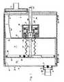
- the pump illustrated in Fig. 1is particularly useful in respirator apparatus for administering artificial respiration or ventilation.
- the pumpincludes a housing 2 formed with an inlet port 3 at one end, and an outlet port 4 at the opposite end.
- the inlet port 3receives an inlet fitting 5 provided with a filter 6 for removing solid particles from the air inletted into the pump housing.
- the outlet port 4receives a coupling fitting 7 for coupling the outlet to the exhalation valve via a delivery tube, as will be described below, and is provided with a one-way valve 8 to permit air to flow only outwardly of the pump housing.
- housing 2The interior of housing 2 includes a cylinder 10 which is closed at one end by end wall 11 of the housing, and at the opposite end by a partition wall 12 fixed within the housing.
- a piston 13is receiprocatably mounted within cylinder 10 to divide the interior of the cylinder into an inlet chamber Ci and an outlet chamber Co.
- the inlet chamber Cicommunicates with the inlet 3 via an intake tube 14 and an opening 15 formed in the fixed partition wall 12; whereas the outlet chamber Co communicates with the outlet via the one-way valve 8 and the coupling fitting 7.
- Piston 13is reciprocatable axially within cylinder 10 by means of a motor M disposed within a drive housing 16 mounted to the fixed partition wall 12.
- Motor Mincludes a rotor 17 fixed to a nut 18 which is rotatably mounted by a rotary bearing 19 to the drive housing 16 via a rubber noise isolator 20.
- Nut 18threadedly receives a threaded screw 21 passing through an opening 22 in the fixed partition wall 12.
- One end of threaded screw 21is fixed to piston 13, and the opposite end is threadedly received within nut 18.
- the end of the drive housing 16 facing the inlet 3 of the pump housingis closed by an end wall 23 integrally formed with a tubular sleeve 24 which receives the end of the threaded screw 21.
- Tubular sleeve 24is of a length to receive the complete length of the threaded screw 21 in its extreme rightmost position and is closed by an end wall 25 so as to completely enclose the screw 21 and thereby to protect it from outside contamination.
- the inner diameter of sleeve 24is enlarged at its inner end and receives a felt lubricating wick 26 for continuously lubricating the screw 21 as it is reciprocated within the tubular sleeve 24.
- a bellows 27encloses screw 21.
- Bellows 27is secured at one end to piston 13 and at the opposite end to the fixed partition wall 12, to thereby protect the part of the screw between the piston and the partition wall against contamination.
- Bellows 27also produces a seal for chamber C 1 preventing air inside it from escaping outwards through the motor housing which is unsealed.
- Piston 13, including its threaded screw 21,is supported for movement within cylinder 10 by the previously-mentioned rotary bearing 19 within drive housing 16, and by a rotary seal 28 along the outer circumference of the piston.
- Bellows 27 and seal 28permit both axial and some rotary movement of piston 13, so that the piston is substantially unrestrained for both such movements.
- rotation of nut 18 receiving screw 21will move screw 21, and thereby also piston 13, axially, and will also permit the piston to rotate somewhat with respect to cylinder 10. The latter function evens out the wear between piston 13 and cylinder 10.
- Piston 13is formed with an opening receiving a one-way valve 30 permitting air to flow only in the direction from the inlet chamber Ci to the outlet chamber Co.
- This one-way valve, and also one-way valve 8 within the outlet 4 which permits air flow only outwardly of the outlet chamber Comay be, for example, umbrella valves, so-called because of their umbrella shape.
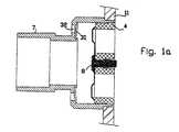
- a further one-way valve 31(see Fig. 1a) is provided in the coupling fitting 7 attached to the outlet port 4 of the pump housing.
- One-way valve 31may be in the form of a valve leaf normally biassed to close an opening 32 leading to the atmosphere, but deflectable (rightwardly, Figs. 1 and 1a) if there is a negative pressure within the coupling fitting 7, to thereby connect the interior of the coupling fitting to the atmosphere.
- Valve 31thus serves the same function as the H-valve usually mounted on the patient air delivery hose, to permit the patient to inhale ambient air in case the respirator fails and there is an internal blockage or restriction.
- the pump housing 2is further provided with supporting feet 33 to permit it to be supported on any suitable horizontal surface.
- Piston 13is supported substantially unrestrained for both axial movement and rotational movement by rotary bearing 19 and seal 28.
- rotary bearing 19 and seal 28are supported substantially unrestrained for both axial movement and rotational movement.
- the patientcan still inhale by virtue of the one-way valve 32 in the coupling fitting 7, since the latter valve will open by a negative pressure produced within the coupling fitting during inspiration under such conditions.
- Fig. 2illustrates a dual-acting pump of substantially the same construction as in Fig. 1 except modified so as to produce two output strokes for each reciprocatory cycle of the piston.
- those parts in the pump of Fig. 2which are common to those in Fig. 1 carry the same reference numerals.
- the dual-acting pump illustrated in Fig. 2includes, in addition to the parts common to the pump of Fig. 1 as described above, also an inlet conduit 40 connecting the inlet 3 to both the chamber Ci and chamber Co, and an outlet conduit 41 connecting the outlet 4 to both chamber Ci and chamber Co.
- the outlet 4includes the one-way valve 8 as in the single-acting pump illustrated in Fig. 1 permitting air flow only outwardly from the outlet chamber Co to the respective end of the outlet duct 41.
- the latter end of duct 41serves the same function as the outlet coupling fitting 7 in Fig. 1, and is provided with the one-way valve 31 normally closing the vent opening 32.
- Another one-way valve 42is provided at the opposite end of the outlet conduit 41 communicating with the inlet chamber Ci, and permitting only outflow of air from that chamber to the outlet conduit.
- Piston 13 in the dual-acting pump illustrated in Fig. 2does not include a one-way valve. Instead, the pump of Fig. 2 includes a one-way valve 43 at one end of the inlet conduit 40, permitting air flow only into the inlet chamber Ci, and a second one-way valve 44 at the opposite end of the inlet conduit 40, permitting air flow only into the outlet chamber Co.
- the exhalation valve assemblyis connected to the pump P as illustrated in Fig. 3 for delivering the air outputted by the pump P to the patient. It includes an exhalation valve 50 and a control valve 60 for controlling the operation of the exhalation valve in order to permit inspiration and exhalation by the patient.
- the control valve 60enables the pressure during both inspiration and exhalation to be preset, e.g., in order to fix the low pressure so that the patient's lungs remain slighly inflated, and/or to prevent a high pressure which may be injurious to the patient.
- Control port 62is connectible to the inlet port 61 to transfer the pressure at the inlet port (which is the same as the pump P outlet pressure) to control chamber 55 of the exhalation valve 50. This moves diaphragm 54 to its closed position (illustrated in Fig. 3), and thereby permits inspiration by the patient via inlet port 51 and outlet port 52.
- Control port 62 of the control valve 60is also connectible to vent 63 to vent control chamber 55 of the exhalation valve 50 to the atmosphere in order to permit the patient to exhale via outlet port 52 and exhalation port 53 leading to the atmosphere.
- control valve 60may also be preset to control the pressure within control chamber 55 of the exhalation valve 50 during exhalation, to thereby preset the exhalation pressure by the patient to cause the patient's lungs to remain slightly inflated during exhalation (which for many patients is beneficial) without requiring an excessive pressure during exhalation such that it may be injurious to the patient.
- control member 64 of the control valve 60is a diaphragm which selectively controls two passageways: one passageway is between the inlet port 61 and the control port 62, whereas the second passageway is between the control port 62 and the atmospheric vent 63.
- Control valve 60includes a hollow metal stem 65 enclosed by an elastomeric tube 66 movable within a bore 67 extending through the control valve.
- One end of hollow stem 65defines the atmospheric vent 63.
- the opposite end of the hollow stemis formed with an enlarged tip 68 which is engageable by diaphragm 64, such that the diaphragm biasses the hollow stem 65 and its elastomeric sleeve 66 leftwardly (Figs. 4 and 5).
- Elastomeric sleeve 66is pre-compressed so that it biasses the metal stem 65 rightwardly, i.e., against diaphragm 64, with the elastomeric sleeve 66 limiting against an annular flange 69 fixed within the control valve 60.
- the control valveincludes a further passageway 70 leading from the control port 62 to diaphragm 64.
- the diaphragm 64acts as a force transmitting means, as well as a dual seal, one for the tip 68, and one on its periphery sealing the inside of the solenoid to atmosphere.
- Resilient elastomeric sleeve 66is also a triple function member, in that: it acts as a spring to urge hollow stem 65 to the right; it acts as a seal with respect to annular flange 69; and it also acts as a seal with respect to the inlet port 61.
- the foregoing arrangement of sleeve 66, tip 68, flange 69 and diaphragm 64assures that the passage to the atmosphere via vent 63 cannot be open when the inlet passage 67 is open.
- the current through the solenoid coil 71is controlled by a control circuit, shown schematically at 73.
- Control circuit 73cyclically controls coil 71 to provide full or partial energization during inspiration, and no energization or partial energization during exhalation, as may be preset by manual presetting means shown schematically as knobs 74 and 75, respectively.
- presetting knob 74controls the cycles of energization of coil 71 and thereby the rate of inspiration/exhalation
- knob 75controls the energizing current to the coil during inspiration and exhalation and thereby the fixed pressure during inspiration and exhalation.
- the force applied by armature 72 against diaphragm 64is sufficient to move the hollow stem 65, including its elastomeric sleeve 66 leftwardly, and thereby away from annular flange 69, to open the passageway from the inlet port 61 through bore 67 and passageway 70 to the control port 62. Accordingly, at this time, the outlet pressure from the pump P is applied to control chamber 55 of the exhalation valve 50, thereby causing diaphragm 54 of that valve to be in its closed position against valve seat 54a, as illustrated in Fig. 3. Accordingly, the flow of air at the outlet of pump P passes from the pump and the air delivery tube 48 via the inlet port 51 and the outlet port 52 of the exhalation valve 50 to the patient.
- diaphragm 64 of control valve 60will assume the position illustrated in Figs. 5 and 5a.
- the pre-stressed condition of the elastomeric tube 66moves the hollow stem 65 rightwardly until the edge of the elastomeric tube engages flange 69, thereby closing the passageway between the inlet port 61 and the control port 62.
- the tip 68 of the hollow stem 65is still in contact with the diaphragm 64, so that the passageway between the tip and the diaphragm is also closed. Accordingly, the pressure existing within control chamber 55 is trapped within that control chamber.
- the exhalation pressuremay be preset according to the particular case by control knob 75.
Landscapes
- Health & Medical Sciences (AREA)
- Pulmonology (AREA)
- General Health & Medical Sciences (AREA)
- Public Health (AREA)
- Anesthesiology (AREA)
- Biomedical Technology (AREA)
- Heart & Thoracic Surgery (AREA)
- Hematology (AREA)
- Life Sciences & Earth Sciences (AREA)
- Animal Behavior & Ethology (AREA)
- Emergency Medicine (AREA)
- Engineering & Computer Science (AREA)
- Veterinary Medicine (AREA)
- Respiratory Apparatuses And Protective Means (AREA)
- Reciprocating Pumps (AREA)
- Massaging Devices (AREA)
- Check Valves (AREA)
- Compressors, Vaccum Pumps And Other Relevant Systems (AREA)
- Compressor (AREA)
- External Artificial Organs (AREA)
Description
- The present invention relates toa reciprocating pump according to the preamble of
claim 8. - Respirator apparatus, sometimes called ventilatorapparatus, is widely used for administering artificialrespiration or ventilatory assistance to a patient.Examples of such apparatus are described in my prior USPatents 4,807,616, 4,823,787 and 4,941,469.
- Moreover, it is already known from US Patent 4,493,614 a pump,which includes a housing and which comprises an inlet at one end, an outlet atanother end, and a valve coupled to said outlet. The same pump also comprises acylinder between said inlet and said outlet, and contains a piston which isreciprocatable axially within said cylinder, and which divides the interior into afirst chamber communicating with the inlet and a second chambercommunicating with said outlet.
- The above pump, nonetheless, does not solve the problem ofobtaining very low mechanism inertia, which would allow a quick reversal of thedirection of movement of the piston.
- An object of the present invention is to provide areciprocating pump particularly usefulin ventilator apparatus, according to claim 1.
- These features permit the pump to beconstructed with very low mechanism inertia, allowingreversal of the piston travel direction very quickly(approximately 5 milliseconds). Thus, a respiratorincluding such a pump may be operated to provide a veryrapid rate of breaths, such as 150 breaths per minute, asrequired for respiration of newborn babies, as well asslower rates required in other applications.
- Preferred embodiments of the invention are definedin the dependent claims 2-17, such as theone-way valve defined in
claim 7 which allows the patient todraw ambient air in case the respirator fails and there isan internal blockage or restriction. In conventionalrespirators, a one-way valve, commonly called an H-valve, isgenerally mounted on the patient air delivery tubesexternally of the respirator. By providing this valve as anintegral part of the coupling fitting which couples the pumphousing to the exhalation valve, a more compact and portablearrangement is produced. - According to a further preferred embodiment of theinvention, there is provided an exhalation valve assemblyaccording to
claim 11. - For example, it is frequently desired to maintaina fixed low pressure in the patient line during exhalationso that the patient's lungs remain slightly inflated. Onthe other hand, the pressure on the line during exhalationmust not be excessive as this can impede exhalation. Theforegoing feature of the invention conveniently enables thepressure during exhalation to be preset to the desired valueaccording to the particular situation.
- Fig. 1 is a vertical sectional view illustratingone form of single-acting pump constructed in accordancewith the present invention and particularly useful inrespirator apparatus;
- Fig. 1a is an enlarged fragmentary view ofFig. 1;
- Fig. 2. is a view similar to Fig. 1 illustrating adual-acting pump constructed in accordance with the presentinvention;
- Fig. 3 is a longitudinal sectional viewillustrating respirator apparatus including one form ofexhalation valve assembly constructed in accordance with thepresent invention and its connections with the pump ofFigs. 1 or 2;
- Figs. 4 and 5 are enlarged views illustrating twodifferent conditions of the control valve in the exhalationvalve assembly of Fig. 3; and
- Fig. 4a and 5a are enlarged fragmentary views ofthe control valve of Figs. 4 and 5, respectively.
- The pump illustrated in Fig. 1 is particularlyuseful in respirator apparatus for administering artificialrespiration or ventilation. The pump includes a
housing 2formed with aninlet port 3 at one end, and anoutlet port 4at the opposite end. Theinlet port 3 receives aninletfitting 5 provided with afilter 6 for removing solidparticles from the air inletted into the pump housing. Theoutlet port 4 receives a coupling fitting 7 for coupling theoutlet to the exhalation valve via a delivery tube, as willbe described below, and is provided with a one-way valve 8to permit air to flow only outwardly of the pump housing. - The interior of
housing 2 includes acylinder 10which is closed at one end byend wall 11 of the housing,and at the opposite end by apartition wall 12 fixed withinthe housing. Apiston 13 is receiprocatably mounted withincylinder 10 to divide the interior of the cylinder into aninlet chamber Ci and an outlet chamber Co. The inletchamber Ci communicates with theinlet 3 via anintake tube 14 and anopening 15 formed in thefixed partition wall 12;whereas the outlet chamber Co communicates with the outletvia the one-way valve 8 and the coupling fitting 7. - Piston 13 is reciprocatable axially within
cylinder 10 by means of a motor M disposed within adrivehousing 16 mounted to the fixedpartition wall 12. Motor Mincludes arotor 17 fixed to anut 18 which is rotatablymounted by a rotary bearing 19 to thedrive housing 16 via arubber noise isolator 20. Nut 18 threadedly receives a threadedscrew 21passing through an opening 22 in thefixed partition wall 12. One end of threadedscrew 21 is fixed topiston 13, andthe opposite end is threadedly received withinnut 18. Theend of thedrive housing 16 facing theinlet 3 of the pump housing is closed by anend wall 23 integrally formed with atubular sleeve 24 which receives the end of the threadedscrew 21.Tubular sleeve 24 is of a length to receive thecomplete length of the threadedscrew 21 in its extremerightmost position and is closed by anend wall 25 so as tocompletely enclose thescrew 21 and thereby to protect itfrom outside contamination. The inner diameter ofsleeve 24is enlarged at its inner end and receives a felt lubricatingwick 26 for continuously lubricating thescrew 21 as it isreciprocated within thetubular sleeve 24.- A
bellows 27 enclosesscrew 21. Bellows 27 issecured at one end topiston 13 and at the opposite end tothefixed partition wall 12, to thereby protect the part ofthe screw between the piston and the partition wall againstcontamination. Bellows 27 also produces a seal for chamberC1 preventing air inside it from escaping outwards throughthe motor housing which is unsealed. - Piston 13, including its threaded
screw 21, issupported for movement withincylinder 10 by the previously-mentionedrotary bearing 19 withindrive housing 16, and byarotary seal 28 along the outer circumference of thepiston. Bellows 27 andseal 28 permit both axial and somerotary movement ofpiston 13, so that the piston issubstantially unrestrained for both such movements. Thus,rotation ofnut 18 receivingscrew 21 will movescrew 21,and thereby also piston 13, axially, and will also permitthe piston to rotate somewhat with respect tocylinder 10.The latter function evens out the wear betweenpiston 13 andcylinder 10. - Piston 13 is formed with an opening receiving aone-
way valve 30 permitting air to flow only in thedirection from the inlet chamber Ci to the outlet chamberCo. This one-way valve, and also one-way valve 8 within theoutlet 4 which permits air flow only outwardly of the outletchamber Co, may be, for example, umbrella valves, so-calledbecause of their umbrella shape. - A further one-way valve 31 (see Fig. 1a) isprovided in the
coupling fitting 7 attached to theoutletport 4 of the pump housing. One-way valve 31 may be in theform of a valve leaf normally biassed to close anopening 32leading to the atmosphere, but deflectable (rightwardly,Figs. 1 and 1a) if there is a negative pressure within thecoupling fitting 7, to thereby connect the interior of thecoupling fitting to the atmosphere. Valve 31 thus serves thesame function as the H-valve usually mounted on the patientair delivery hose, to permit the patient to inhale ambientair in case the respirator fails and there is an internalblockage or restriction. - The
pump housing 2 is further provided withsupportingfeet 33 to permit it to be supported on anysuitable horizontal surface. - The operation of the pump illustrated in Fig. 1will be apparent from the above description. Thus, whenmotor M is energized in one direction, its
rotor 17 rotatesnut 18 to movescrew 21, and thereby piston 13, in onedirection, e.g., leftwardly, to contract the outlet chamberCo, thereby forcing air out through the outlet one-way valve 8. During this movement ofpiston 13, its one-way valve 30is closed, thereby preventing air in the inlet chamber Cifrom entering the outlet chamber Co. - When motor M is energized in the oppositedirection,
screw 21, and thereby piston 13, are moved in theopposite direction, e.g., rightwardly. This expands theoutlet chamber Co and contracts the inlet chamber Ci,whereby air from the inlet chamber is drawn into the outletchamber via one-way valve 30. One-way valve 8 is closed andthereby does not permit any air to flow out of the outletchamber. - Piston 13 is supported substantially unrestrainedfor both axial movement and rotational movement by rotarybearing 19 and
seal 28. Thus, during its axial displacementby the rotation ofnut 18, it will be free to undergo somerotational movement, which has been found to be advantageous in that this evens out the wear around the circumference ofseal 28 to extend its life. - In case the respirator fails and there is aninternal blockage or restriction in the respirator, thepatient can still inhale by virtue of the one-
way valve 32in the coupling fitting 7, since the latter valve will openby a negative pressure produced within the coupling fittingduring inspiration under such conditions. - It will thus be seen that in the pump of Fig. 1each complete reciprocatory cycle of
piston 13 produces oneoutput stroke of air via theoutlet port 4. The pumpillustrated in Fig. 1 is therefore a single-acting pump. - Fig. 2 illustrates a dual-acting pump ofsubstantially the same construction as in Fig. 1 exceptmodified so as to produce two output strokes for eachreciprocatory cycle of the piston. To faciliateunderstanding, those parts in the pump of Fig. 2 which arecommon to those in Fig. 1 carry the same referencenumerals.
- The dual-acting pump illustrated in Fig. 2includes, in addition to the parts common to the pump ofFig. 1 as described above, also an
inlet conduit 40connecting theinlet 3 to both the chamber Ci and chamberCo, and anoutlet conduit 41 connecting theoutlet 4 to bothchamber Ci and chamber Co. Theoutlet 4 includes the one-wayvalve 8 as in the single-acting pump illustrated in Fig. 1permitting air flow only outwardly from the outlet chamberCo to the respective end of theoutlet duct 41. The latterend ofduct 41 serves the same function as the outletcoupling fitting 7 in Fig. 1, and is provided with theone-way valve 31 normally closing thevent opening 32.Another one-way valve 42 is provided at the opposite end oftheoutlet conduit 41 communicating with the inlet chamberCi, and permitting only outflow of air from that chamber tothe outlet conduit. Piston 13 in the dual-acting pump illustrated inFig. 2 does not include a one-way valve. Instead, the pump of Fig. 2 includes a one-way valve 43 at one end of theinlet conduit 40, permitting air flow only into the inletchamber Ci, and a second one-way valve 44 at the oppositeend of theinlet conduit 40, permitting air flow only intothe outlet chamber Co.- It will be seen that the dual-acting pumpillustrated in Fig. 2 operates in the same manner as thesingle-acting pump illustrated in Fig. 1, except that itprovides two pumping strokes for each reciprocatory cycle ofthe
piston 13. - Fig. 3 illustrates respirator apparatus includinga pump P and an exhalation valve assembly for delivering theair produced by the pump to the patient. The pump P may beeither the single-acting pump of Fig. 1, or the dual-actingpump of Fig. 2. For purposes of example, it is describedbelow using the dual-acting pump of Fig. 2. The outlet ofthat pump, as shown in Fig. 2, includes an
air delivery tube 48, and apressure control tube 49, both connected to therespective end of theoutlet conduit 41 serving as thecoupling fitting 7 in Fig. 1. - The exhalation valve assembly is connected to thepump P as illustrated in Fig. 3 for delivering the airoutputted by the pump P to the patient. It includes an
exhalation valve 50 and acontrol valve 60 for controllingthe operation of the exhalation valve in order to permitinspiration and exhalation by the patient. As will bedescribed more particularly below, thecontrol valve 60enables the pressure during both inspiration and exhalationto be preset, e.g., in order to fix the low pressure so thatthe patient's lungs remain slighly inflated, and/or toprevent a high pressure which may be injurious to thepatient. - The
exhalation valve 50 includes aninlet port 51connected to theair delivery tube 48 at the outlet of thepump P; anoutlet port 52 for connection to the patient; anexhalation port 53 leading to the atmosphere; and a valvemember 54 connecting theoutlet port 52 either to theinlet port 51 or to theexhalation port 53. Valve member 54 is inthe form of a diaphragm seatable on avalve seat 54a andcontrolled by the differential pressure between that at theinlet port 51 on one side of the diaphragm, and acontrolchamber 55 on the opposite side of the diaphragm.Controlchamber 55 is connected by atube 56 to thecontrol valve 60, such that the operation of the control valve controlsthe pressure withinchamber 55, and thereby the operation ofvalve member 54. Control valve 60 includes aninlet port 61connected viatube 49 to the outlet of pump P; acontrolport 62 connected viatube 56 to controlchamber 55 of theexhalation valve 50; avent 63 leading to the atmosphere;and acontrol member 64.Control member 64 is movable to afirst position (shown in Figs. 4 and 4a) connecting thecontrol port 62 to theinlet port 61, or to a secondposition (shown in Figs. 5 and 5a) connecting thecontrolport 62 to thevent 63.Control port 62 is connectible to theinlet port 61 to transfer the pressure at the inlet port (which is thesame as the pump P outlet pressure) to controlchamber 55 oftheexhalation valve 50. This moves diaphragm 54 to itsclosed position (illustrated in Fig. 3), and thereby permitsinspiration by the patient viainlet port 51 andoutlet port 52.Control port 62 of thecontrol valve 60 is alsoconnectible to vent 63 to ventcontrol chamber 55 of theexhalation valve 50 to the atmosphere in order to permit thepatient to exhale viaoutlet port 52 andexhalation port 53leading to the atmosphere. As will be described below,control valve 60 may also be preset to control the pressurewithincontrol chamber 55 of theexhalation valve 50 duringexhalation, to thereby preset the exhalation pressure by thepatient to cause the patient's lungs to remain slightlyinflated during exhalation (which for many patients isbeneficial) without requiring an excessive pressure duringexhalation such that it may be injurious to the patient.- As shown in Figs. 4 and 5,
control member 64 ofthecontrol valve 60 is a diaphragm which selectivelycontrols two passageways: one passageway is between theinlet port 61 and thecontrol port 62, whereas the secondpassageway is between thecontrol port 62 and theatmospheric vent 63. Control valve 60 includes a hollow metal stem 65enclosed by anelastomeric tube 66 movable within abore 67extending through the control valve. One end ofhollow stem 65 defines theatmospheric vent 63. The opposite end of thehollow stem is formed with anenlarged tip 68 which isengageable bydiaphragm 64, such that the diaphragm biassesthehollow stem 65 and itselastomeric sleeve 66 leftwardly(Figs. 4 and 5).Elastomeric sleeve 66, however, ispre-compressed so that it biasses themetal stem 65rightwardly, i.e., againstdiaphragm 64, with theelastomeric sleeve 66 limiting against anannular flange 69fixed within thecontrol valve 60. The control valveincludes afurther passageway 70 leading from thecontrolport 62 todiaphragm 64.Control valve 60 further includes a solenoidcomprising acoil 71 and an armature orclapper 72 which isattracted magnetically towards the housing of the controlvalve according to the magnetic force generated by thecurrent passing throughcoil 71.Armature 72 may bepositioned according to any one of three modes, dependingon the relative forces applied to it:- (1) A pressure relief mode, in which the
armature 72 is urged to the right by diaphragm 64 (see Fig. 5) sincethe diaphragm is exposed to the pressure atoutlet 62. Inthis relief position, the pressure atoutlet 62 causes thediaphragm to disengage fromtip 68 ofstem 65, to allow airto escape from theoutlet port 62 to the atmosphere viaatmospheric vent 63, thereby reducing the pressure in thecontrol chamber 55. - (2) A "hold" mode, in which armature 72 pressesdiaphragm 64 against the
tip 68 of stem 65 (Fig. 4). In this position, there is no flow between theoutlet port 62and atmosphere orinlet port 61, so that the pressure at theoutlet port 62 is maintained. - (3) A "pressure" mode, in which armature 72presses diaphragm 64 against
tip 68 ofstem 65, and furtherpushes the stem (leftwardly) to create a passage betweeninlet port 61 andoutlet port 62. In this mode, pressure atthe outlet port is increased until it reaches the pressureof theinlet port 61, or until such time as the pressureapplied to diaphragm 64 overcomes the magnetic force appliedtoarmature 72, moving it to the right to seal off thepassageway inannular flange 69. In this mode, modulatingthe current through coil throughcoil 71 will thus modulatethe pressure atport 62, and thereby modulate the pressurein thecontrol chamber 55 of theexhalation valve 50. - It is important to note that in the "hold" mode(2) above the armature is moving back and forth in a verysmall travel, pivoting around its resting point on thebottom edge. This pivotal movement is substantiallyfrictionless, and thus provides a modulating valve thatproduces as essentially hysteresis-free control of theexhalation valve.
- It is also important to note that the
diaphragm 64acts as a force transmitting means, as well as a dual seal,one for thetip 68, and one on its periphery sealing theinside of the solenoid to atmosphere. Resilientelastomericsleeve 66 is also a triple function member, in that: itacts as a spring to urgehollow stem 65 to the right; itacts as a seal with respect toannular flange 69; and italso acts as a seal with respect to theinlet port 61. Theforegoing arrangement ofsleeve 66,tip 68,flange 69 anddiaphragm 64 assures that the passage to the atmosphere viavent 63 cannot be open when theinlet passage 67 is open. - The current through the
solenoid coil 71 iscontrolled by a control circuit, shown schematically at 73.Control circuit 73cyclically controls coil 71 to providefull or partial energization during inspiration, and no energization or partial energization during exhalation, asmay be preset by manual presetting means shown schematicallyasknobs knob 74controls the cycles of energization ofcoil 71 and therebythe rate of inspiration/exhalation, whereasknob 75 controlsthe energizing current to the coil during inspiration andexhalation and thereby the fixed pressure during inspirationand exhalation. - The operation of the respirator apparatusillustrated in Fig. 3 will now be described particularlywith reference to Figs. 4, 4a, 5 and 5a.
- Figs. 4 and 4a illustrate the position of the
diaphragm 64 in thecontrol valve 60 during inspiration. Atthis time, full energizing current is supplied bycontrolcircuit 73 tosolenoid coil 71 causing the solenoid to drawitsarmature 72 to the limit position illustrated in Figs. 4and 4a. In this limit position,armature 72 pressesdiaphragm 64 against themetal tip 68 of thehollow stem 65,closing the passageway fromcontrol port 62 to theatmospheric vent 63 via the hollow stem. The force appliedbyarmature 72 againstdiaphragm 64 is sufficient to movethehollow stem 65, including itselastomeric sleeve 66leftwardly, and thereby away fromannular flange 69, to openthe passageway from theinlet port 61 throughbore 67 andpassageway 70 to thecontrol port 62. Accordingly, at thistime, the outlet pressure from the pump P is applied tocontrolchamber 55 of theexhalation valve 50, therebycausing diaphragm 54 of that valve to be in its closedposition againstvalve seat 54a, as illustrated in Fig. 3.Accordingly, the flow of air at the outlet of pump P passesfrom the pump and theair delivery tube 48 via theinletport 51 and theoutlet port 52 of theexhalation valve 50 tothe patient. - Now, if the current through the
solenoid coil 71is reduced to zero,diaphragm 64 ofcontrol valve 60 willassume the position illustrated in Figs. 5 and 5a. In thisposition, the pre-stressed condition of theelastomeric tube 66 moves thehollow stem 65 rightwardly until the edge ofthe elastomeric tube engagesflange 69, thereby closing thepassageway between theinlet port 61 and thecontrol port 62. Thetip 68 of thehollow stem 65, however, is still incontact with thediaphragm 64, so that the passagewaybetween the tip and the diaphragm is also closed.Accordingly, the pressure existing withincontrol chamber 55is trapped within that control chamber. However, since thearmature 72 is in its rightmost position, very little forceis applied bydiaphragm 64 against theouter tip 68 of thehollow stem 65. Therefore a small additional pressureapplied to the diaphragm from thecontrol port 62 willdisplace the diaphragm (rightwardly, Figs. 5 and 5a), toopen a passageway between the diaphragm and theouter tip 68of the hollow stem, thereby venting to the atmosphere thepressure withincontrol chamber 55 via theatmospheric vent 63. Thus, when the patient exhales via theexhalation port 53, diaphragm 54 of the exhalation valve unseats fromseat 54a to thereby connect theoutlet port 52 to theexhalationport 53, permitting the patient to exhale to theatmosphere. - It will thus be seen that the larger the magnitudeof current passed through
coil 71 during exhalation, thegreater will be the force applied by thearmature 72 of thesolenoid againstdiaphragm 64 resisting the opening of thepassageway between the diaphragm and thetip 68 of thehollow stem 65 leading to theatmospheric vent 63, andtherefore the greater will be the fixed pressure applied bycontrol chamber 55 during inspiration and exhalation.Accordingly, the exhalation pressure may be preset accordingto the particular case bycontrol knob 75. - Where technical features mentioned in any claim are followed byreference signs, those reference signs have been included forthe sole purpose of increasing the intelligibility of the claimsand accordingly, such reference signs do not have any limitingeffect on the scope of each element identified by way of exampleby such reference signs.
Claims (17)
- A reciprocating pump particularly for use in a ventilator apparatus,comprising a pump housing (2) having an inlet (3) at one end, an outlet (4) atanother end, a valve (8) coupled to said outlet (4), a cylinder (10) between saidinlet (3) and outlet (4) and a piston (13) reciprocatable axially within saidcylinder (10);
a fixed wall (12) within said housing (2) having a passageway (15)therethrough communicating with said inlet (3);
a drive housing (16) fixed to said wall and including a motor (M) having arotor (17) rotatable by the energization of said motor;
a nut (18) rotatable within said drive housing (16) and fixed to said rotor(17) to rotate therewith; and
a screw (21) threadedly coupled to said nut (18) and engaging at one endsaid piston (13);
characterized in that said piston (13) divides the interior of said cylinderinto a first chamber (Ci) communicating with said inlet (3), and a secondchamber (Co) communicating with said outlet (4);
said piston (13) being supported by said nut (18) mounted in a singlerotatable bearing (19) between said nut (18) and the drive housing (16) and by aseal (28) between said piston and the cylinder. - The pump according to Claim 1, wherein said piston (13) issubstantially engaging in a fixed manner the screw (21), such that forward andreverse rotation of the nut (18) by the motor (M) reciprocating said screw leadsthe piston fixed on the one side thereto to axially slide in the cylinder (10), andon the other side it leads said piston to rotate with respect to the cylinder,thereby evening out the wear of said seal (28) between said piston and saidcylinder.
- The pump according to Claim 1, further including a noise isolator(20) interposed between said rotatable nut (18) and said drive housing (16).
- The pump according to Claim 1, further including a tubular sleeve(24) fixed to said drive housing in alignment with said screw for receiving andenclosing one end of said screw opposite to that fixed to said piston.
- The pump according to Claim 4, wherein said tubular sleeveincludes a lubricating wick (26) for lubricating the screw when received therein.
- The pump according to Claim 1, further including a bellows (27)enclosing said screw (21) and having one end fixed to said wall (12) and theopposite end engaging said piston (13).
- The pump according to Claim 6, wherein said valve (8) coupled tosaid outlet (4) is a one-way valve permitting fluid flow only in the directionfrom the second chamber (Co) outwardly of the pump housing (2),
- The pump according to Claim 7, wherein said piston (13) includes aone-way valve (30) permitting fluid flow only in the direction from the firstchamber (Ci) to the second chamber (Co).
- The pump according to claim 1, wherein said pump housing (2)further includes:an inlet conduit (40) connecting said housing inlet (3) to both saidchambers (Ci; Co) and having one-way valves (43,44) which permit fluid flowonly in the direction from said housing inlet (3) into the respective chamber;and an outlet conduit (41) connecting said housing outlet (4) to both saidchambers (Ci; Co) and having one-way valves (8, 42) which permit fluid flowonly in the direction from the respective chamber to said housing outlet.
- The pump according to claim 1, where said valve (8) is anexhalation valve (50) which is coupled to the housing outlet (4) via a couplingfitting (7), said coupling fitting (7) including a one-way valve (31) which isnormally closed, but which is automatically opened by a negative pressurewithin said coupling fitting (7) to connect the interior of said coupling fitting to the atmosphere.
- The pump according to Claim 1, wherein said exhalation valve (50)comprises:an exhalation (51) inlet port connected to the outlet (4) of said pumphousing (2), an exhalation (52) outlet port for connection to the patient, anexhalation port (53) leading to the atmosphere, a valve member (54) connectingsaid outlet port (52) either to said inlet port (51) or to said exhalation port (53),and a control chamber (55) for controlling the operation of said valve member(54) in response to the pressure in said control chamber (55);and a control valve (60) for controlling the pressure within said controlchamber (55) to increase the pressure therein during inspiration to cause thevalve member (54) of the exhalation valve (50) to connect the outlet port (52) tosaid inlet port (51), and to decrease the pressure in the control chamber (55)during exhalation to thereby cause the valve member (54) of the exhalationvalve (50) to connect the outlet port (52) to the exhalation port (53).
- The pump according to Claim 11, wherein said control valve (60)includes:a control inlet port (61) connected to the outlet (4) of said pump housing(2);a control port (62) connected to said control chamber (55) of theexhalation valve (50);a vent (63) leading to the atmosphere;a valve member (64) movable to a first position during inspiration to opena first passageway connecting the control chamber (55) of the exhalation valve(50) to the control inlet port (61) of the control valve (60), and thereby to theoutlet (4) of the pump housing (2), or to a second position during exhalation toclose said first passageway and to open a second passageway connecting thecontrol chamber (55) of the exhalation valve (50) to said vent (63) leading to theatmosphere;a solenoid (71) having an armature (72) controlling the pressure in thecontrol chamber (55) of the exhalation valve (50) according to the energization of the solenoid;and a circuit (73) for controlling the energization of said solenoid suchthat during inspiration said valve member (64) is moved to said first position,and during exhalation said valve member (64) is moved to said second position.
- The pump according to Claim 12, wherein said electrical circuit(73) includes presettable means for presetting a predetermined partialenergization of the solenoid to modulate the pressure in the control chamber ofthe exhalation valve during inspiration and exhalation.
- The pump according to Claim 13, wherein said valve member (64)includes a hollow stem (65) whose interior is exposed at one end to theatmosphere; and a diaphragm (64) engageable with the opposite end of saidhollow stem; said armature (72) of the solenoid (71) acting against saiddiaphragm to urge the hollow stem to said first position during inspiration.
- The pump according to Claim 14, wherein said valve member (64)further includes an elastomeric tube (66) enclosing said hollow stem (65) andeffecttive to urge said hollow stem to said second position during exhalation.
- The pump according to Claim 12, where said control valve (60)includes presettable means for presetting a predetermined partial pressure in thecontrol chamber (55) during exhalation to thereby preset the exhalation pressureto open said exhalation valve.
- The pump according to Claim 12, wherein said armature (72) pivotsabout an edge thereof, thereby providing an essentially hysteresis-free control ofsaid exhalation valve (50).
Applications Claiming Priority (2)
| Application Number | Priority Date | Filing Date | Title |
|---|---|---|---|
| US202950 | 1994-02-28 | ||
| US08/202,950US5484270A (en) | 1994-02-28 | 1994-02-28 | Pump particularly useful in respirator apparatus and exhalation valve assembly therefor |
Publications (3)
| Publication Number | Publication Date |
|---|---|
| EP0669141A2 EP0669141A2 (en) | 1995-08-30 |
| EP0669141A3 EP0669141A3 (en) | 1996-03-27 |
| EP0669141B1true EP0669141B1 (en) | 2002-12-04 |
Family
ID=22751871
Family Applications (1)
| Application Number | Title | Priority Date | Filing Date |
|---|---|---|---|
| EP95102584AExpired - LifetimeEP0669141B1 (en) | 1994-02-28 | 1995-02-23 | Piston pump and exhalation valve |
Country Status (6)
| Country | Link |
|---|---|
| US (3) | US5484270A (en) |
| EP (1) | EP0669141B1 (en) |
| JP (3) | JPH08317979A (en) |
| CN (1) | CN1119183C (en) |
| CA (1) | CA2143161C (en) |
| DE (1) | DE69529005T2 (en) |
Families Citing this family (85)
| Publication number | Priority date | Publication date | Assignee | Title |
|---|---|---|---|---|
| DE19633170A1 (en)* | 1996-08-17 | 1998-02-19 | Teves Gmbh Alfred | Electric motor / pump unit |
| SE9704300D0 (en)* | 1997-11-20 | 1997-11-20 | Siemens Elema Ab | Gas pressure generator |
| SE9800561D0 (en)* | 1998-02-25 | 1998-02-25 | Siemens Elema Ab | Bellows device in a fan / anesthetic system |
| SE9802123D0 (en)* | 1998-06-15 | 1998-06-15 | Siemens Elema Ab | directional valve |
| JP3768689B2 (en)* | 1998-07-31 | 2006-04-19 | スズキ株式会社 | Ventilator |
| US6283122B1 (en)* | 1999-03-10 | 2001-09-04 | Flight Medical Ltd. | Exhalation valve for respirator |
| US6631717B1 (en)* | 1999-10-21 | 2003-10-14 | Ntc Technology Inc. | Re-breathing apparatus for non-invasive cardiac output, method of operation, and ventilator circuit so equipped |
| DE19958913A1 (en)* | 1999-12-07 | 2001-06-28 | Bosch Gmbh Robert | Electromagnetically actuated valve |
| US6595212B1 (en)* | 2000-04-17 | 2003-07-22 | Richard J. Arnott | Method and apparatus for maintaining airway patency |
| SE523375C2 (en)* | 2001-06-19 | 2004-04-13 | Aneo Ab | Lung ventilator adapted for patients during intravenous, switchable between assisted and spontaneous breathing. |
| SE523653C2 (en)* | 2001-06-19 | 2004-05-04 | Aneo Ab | Pulmonary ventilator adapted for patients under intravenous anesthesia, switchable between assisted and spontaneous breathing |
| ATE392228T1 (en)* | 2001-06-27 | 2008-05-15 | Fisher & Paykel Healthcare Ltd | EXHAUSTING VALVE FOR A NASAL VENTILATION MASK |
| CN100335366C (en) | 2002-01-17 | 2007-09-05 | 斯考脱航空股份有限公司 | Valve Box Assembly for Oxygen Mask Dispensing Containers |
| FR2858236B1 (en)* | 2003-07-29 | 2006-04-28 | Airox | DEVICE AND METHOD FOR SUPPLYING RESPIRATORY GAS IN PRESSURE OR VOLUME |
| US7152597B2 (en)* | 2003-09-25 | 2006-12-26 | Datex-Ohmeda, Inc. | Breathing circuit adapter |
| CA2451907C (en)* | 2003-12-18 | 2011-09-27 | Ici Solutions Inc. | Reciprocating pump with screw actuator |
| WO2005115087A2 (en)* | 2004-05-27 | 2005-12-08 | Oridion Medical 1987 Ltd. | Capnography apparatus |
| US7438537B2 (en)* | 2005-03-09 | 2008-10-21 | Dosmatic Usa, Inc. | Liquid additive injection pump with mixing chamber and one way valve |
| JP5256023B2 (en)* | 2005-05-02 | 2013-08-07 | レスメ・パリ | Respiratory assistance device with gas regulating valve and respiratory assistance method |
| NZ562501A (en)* | 2005-05-02 | 2010-10-29 | Saime Sarl | A gas regulating valve for a breathing assistance device that allows control of the opening of leakage orfice |
| DE102006012174A1 (en)* | 2006-03-16 | 2007-09-20 | Pari GmbH Spezialisten für effektive Inhalation | Inhalation therapy devices compressor |
| JP4554624B2 (en)* | 2007-01-22 | 2010-09-29 | ソニー株式会社 | Information processing apparatus and information processing method |
| EP1985328B1 (en)* | 2007-04-27 | 2012-10-17 | MAP Medizin-Technologie GmbH | Sound absorber and method for absorbing sound |
| US20220193352A1 (en)* | 2007-05-30 | 2022-06-23 | Gilbert Jacobus Kuypers | Electrically operable resuscitators |
| US8251876B2 (en) | 2008-04-22 | 2012-08-28 | Hill-Rom Services, Inc. | Breathing exercise apparatus |
| USD603435S1 (en) | 2008-08-29 | 2009-11-03 | Dosmatic Usa, Inc. | Dosage piston retention clip |
| USD603427S1 (en) | 2008-09-15 | 2009-11-03 | Dosmatic Usa, Inc. | On-off plunger |
| US8302602B2 (en) | 2008-09-30 | 2012-11-06 | Nellcor Puritan Bennett Llc | Breathing assistance system with multiple pressure sensors |
| USD602512S1 (en) | 2008-10-24 | 2009-10-20 | Dosmatic Usa, Inc. | Piston assembly |
| US8303276B2 (en)* | 2008-12-10 | 2012-11-06 | Covidien Lp | Pump and exhalation valve control for respirator apparatus |
| US8434479B2 (en) | 2009-02-27 | 2013-05-07 | Covidien Lp | Flow rate compensation for transient thermal response of hot-wire anemometers |
| CN101537214B (en)* | 2009-04-29 | 2014-08-06 | 王利强 | Negative pressure pulsation therapeutic instrument |
| JP4666099B2 (en)* | 2009-10-28 | 2011-04-06 | ソニー株式会社 | Information processing apparatus and information processing method |
| US20110126832A1 (en)* | 2009-12-01 | 2011-06-02 | Nellcor Puritan Bennett Llc | Exhalation Valve Assembly |
| US8469030B2 (en)* | 2009-12-01 | 2013-06-25 | Covidien Lp | Exhalation valve assembly with selectable contagious/non-contagious latch |
| US8439037B2 (en) | 2009-12-01 | 2013-05-14 | Covidien Lp | Exhalation valve assembly with integrated filter and flow sensor |
| US8439036B2 (en)* | 2009-12-01 | 2013-05-14 | Covidien Lp | Exhalation valve assembly with integral flow sensor |
| US8469031B2 (en)* | 2009-12-01 | 2013-06-25 | Covidien Lp | Exhalation valve assembly with integrated filter |
| US9629971B2 (en) | 2011-04-29 | 2017-04-25 | Covidien Lp | Methods and systems for exhalation control and trajectory optimization |
| US10137264B2 (en) | 2011-07-13 | 2018-11-27 | Fisher & Paykel Healthcare Limited | Respiratory assistance apparatus |
| EP4169560B1 (en)* | 2011-07-13 | 2025-09-17 | Fisher & Paykel Healthcare Limited | Bearing mount for a compressor or blower for providing respiratory assistance |
| US9364624B2 (en) | 2011-12-07 | 2016-06-14 | Covidien Lp | Methods and systems for adaptive base flow |
| US9498589B2 (en) | 2011-12-31 | 2016-11-22 | Covidien Lp | Methods and systems for adaptive base flow and leak compensation |
| JP6170947B2 (en) | 2012-02-02 | 2017-07-26 | アイアセット アーゲー | Soundproof enclosure for ventilators |
| US9180271B2 (en) | 2012-03-05 | 2015-11-10 | Hill-Rom Services Pte. Ltd. | Respiratory therapy device having standard and oscillatory PEP with nebulizer |
| US9144658B2 (en) | 2012-04-30 | 2015-09-29 | Covidien Lp | Minimizing imposed expiratory resistance of mechanical ventilator by optimizing exhalation valve control |
| GB2505689B (en)* | 2012-09-07 | 2018-11-21 | Intersurgical Ag | Improvements to valve assemblies |
| AU2015218543B2 (en)* | 2012-12-18 | 2017-09-07 | Fisher & Paykel Healthcare Limited | Impeller and motor assembly |
| CN205515844U (en)* | 2012-12-18 | 2016-08-31 | 费雪派克医疗保健有限公司 | Breathe auxiliary device and be used for assembly of motor |
| US9206921B1 (en) | 2013-01-02 | 2015-12-08 | Jansen's Aircraft Systems Controls, Inc. | Sealed solenoid and solenoid valve |
| USD731049S1 (en) | 2013-03-05 | 2015-06-02 | Covidien Lp | EVQ housing of an exhalation module |
| USD731065S1 (en) | 2013-03-08 | 2015-06-02 | Covidien Lp | EVQ pressure sensor filter of an exhalation module |
| USD692556S1 (en) | 2013-03-08 | 2013-10-29 | Covidien Lp | Expiratory filter body of an exhalation module |
| USD701601S1 (en) | 2013-03-08 | 2014-03-25 | Covidien Lp | Condensate vial of an exhalation module |
| USD736905S1 (en) | 2013-03-08 | 2015-08-18 | Covidien Lp | Exhalation module EVQ housing |
| USD744095S1 (en) | 2013-03-08 | 2015-11-24 | Covidien Lp | Exhalation module EVQ internal flow sensor |
| USD731048S1 (en) | 2013-03-08 | 2015-06-02 | Covidien Lp | EVQ diaphragm of an exhalation module |
| USD693001S1 (en) | 2013-03-08 | 2013-11-05 | Covidien Lp | Neonate expiratory filter assembly of an exhalation module |
| US9950135B2 (en) | 2013-03-15 | 2018-04-24 | Covidien Lp | Maintaining an exhalation valve sensor assembly |
| WO2015136407A1 (en)* | 2014-03-11 | 2015-09-17 | Koninklijke Philips N.V. | Compact dual limb diaphragm valve system and method cross-reference to related applications |
| CN103933648B (en)* | 2014-03-26 | 2016-09-07 | 北京雅果科技有限公司 | A kind of diaphram stimulates suction and discharge system |
| JP6535958B2 (en)* | 2014-07-07 | 2019-07-03 | 国立大学法人 東京大学 | Valve, fluid device, fluid control method, and valve manufacturing method |
| US11247015B2 (en) | 2015-03-24 | 2022-02-15 | Ventec Life Systems, Inc. | Ventilator with integrated oxygen production |
| US10245406B2 (en) | 2015-03-24 | 2019-04-02 | Ventec Life Systems, Inc. | Ventilator with integrated oxygen production |
| EP4186548A1 (en) | 2015-04-02 | 2023-05-31 | Hill-Rom Services PTE. LTD. | Mask leakage detection for a respiratory device |
| USD775345S1 (en) | 2015-04-10 | 2016-12-27 | Covidien Lp | Ventilator console |
| CN105477755B (en)* | 2016-02-16 | 2017-12-12 | 重庆医科大学附属第一医院 | The bag respirator of control tidal volume can be extruded automatically |
| US10773049B2 (en) | 2016-06-21 | 2020-09-15 | Ventec Life Systems, Inc. | Cough-assist systems with humidifier bypass |
| CA3033836A1 (en) | 2016-08-16 | 2018-02-22 | Fisher & Paykel Healthcare Limited | Pressure regulating valve |
| DE102016220812A1 (en)* | 2016-10-24 | 2018-04-26 | Hamilton Medical Ag | Exhalation valve for a ventilator with low-noise valve design |
| CN106693094A (en)* | 2017-01-03 | 2017-05-24 | 上海理工大学 | Electromagnetically driven left-right reciprocating liquid pumping mechanism |
| CN114288512B (en)* | 2017-04-23 | 2024-12-13 | 费雪派克医疗保健有限公司 | Respiratory assistance equipment |
| WO2019016094A1 (en) | 2017-07-17 | 2019-01-24 | Philip Morris Products S.A. | Simulated respiratory tract |
| CN108837254A (en)* | 2018-05-11 | 2018-11-20 | 东台市海船用设备有限公司 | A kind of elastic force linking respirator peculiar to vessel |
| CN108815664B (en)* | 2018-05-11 | 2021-03-23 | 东台市海一船用设备有限公司 | Sliding limiting type marine respirator |
| WO2019221852A1 (en) | 2018-05-13 | 2019-11-21 | Ahmad Samir Saleh | Portable medical ventilator system using portable oxygen concentrators |
| DE102018004341A1 (en)* | 2018-05-31 | 2019-12-05 | Drägerwerk AG & Co. KGaA | Ventilator and method of operating a ventilator |
| JP7706368B2 (en) | 2019-01-15 | 2025-07-11 | フィリップ・モーリス・プロダクツ・ソシエテ・アノニム | perforated structure |
| DE102019003643A1 (en)* | 2019-05-24 | 2020-11-26 | Drägerwerk AG & Co. KGaA | Arrangement with an inspiration valve for a ventilation system |
| US11896767B2 (en) | 2020-03-20 | 2024-02-13 | Covidien Lp | Model-driven system integration in medical ventilators |
| EP4127475B1 (en) | 2020-03-31 | 2024-10-23 | Graco Minnesota Inc. | Electrically operated pump for a plural component spray system |
| AU2021246059A1 (en)* | 2020-03-31 | 2022-10-06 | Graco Minnesota Inc. | Electrically operated displacement pump |
| CN113898560A (en)* | 2021-08-30 | 2022-01-07 | 谭浩 | Pressure-relief-preventing energy-saving gas compressor |
| CN113700476B (en)* | 2021-09-10 | 2023-07-25 | 中海油田服务股份有限公司 | Sample reciprocating pump device under while-drilling well |
| US11946564B2 (en) | 2022-08-10 | 2024-04-02 | Thomas D. Mueller | Rotary valve for use with a fluid proportioner |
Family Cites Families (29)
| Publication number | Priority date | Publication date | Assignee | Title |
|---|---|---|---|---|
| US32553A (en)* | 1861-06-18 | Churn | ||
| US1713219A (en)* | 1926-07-28 | 1929-05-14 | Duro Co | Pump |
| DE1491776A1 (en)* | 1965-07-21 | 1969-05-22 | Mayr Maximus Ag | Artificial breathing pump |
| US3486502A (en)* | 1966-09-09 | 1969-12-30 | Dynasciences Corp | Positive pressure flow cut-off respiration system |
| FR2032807A5 (en)* | 1969-02-11 | 1970-11-27 | Castiglioni Ferdinando | |
| FR2106641A5 (en)* | 1970-09-18 | 1972-05-05 | Magne Guy | |
| FR2106841A5 (en)* | 1970-09-25 | 1972-05-05 | Saporta Jose | |
| US3918447A (en)* | 1972-08-19 | 1975-11-11 | John S Inkster | Ventilators |
| US3932066A (en)* | 1973-10-02 | 1976-01-13 | Chemetron Corporation | Breathing gas delivery cylinder for respirators |
| US4182599A (en)* | 1973-10-02 | 1980-01-08 | Chemetron Corporation | Volume-rate respirator system and method |
| GB1558060A (en)* | 1975-07-29 | 1979-12-19 | Medishield Corp Ltd | Lung ventilator |
| US4145165A (en)* | 1977-03-04 | 1979-03-20 | California Institute Of Technology | Long stroke pump |
| US4276003A (en)* | 1977-03-04 | 1981-06-30 | California Institute Of Technology | Reciprocating piston pump system with screw drive |
| DE2735555C2 (en)* | 1977-08-06 | 1982-09-09 | Drägerwerk AG, 2400 Lübeck | Ventilator for emergency care |
| USRE32553E (en) | 1978-11-29 | 1987-12-08 | Exhalation valve assembly | |
| US4454893A (en)* | 1981-11-30 | 1984-06-19 | Puritan-Bennett Corp. | Low-noise diaphragm for use in exhalation valve |
| US4493614A (en)* | 1982-10-08 | 1985-01-15 | Lifecare Services, Inc. | Pump for a portable ventilator |
| DE3422023C2 (en)* | 1984-06-14 | 1987-04-23 | Drägerwerk AG, 2400 Lübeck | Lung regulator for breathing apparatus |
| US4527557A (en)* | 1984-11-01 | 1985-07-09 | Bear Medical Systems, Inc. | Medical ventilator system |
| US4712580A (en)* | 1986-03-21 | 1987-12-15 | Intertech Resources Inc. | Exhalation valve assembly |
| US4717117A (en)* | 1986-12-08 | 1988-01-05 | Bendix Electronics Limited | Vacuum valve using improved diaphragm |
| GB8704104D0 (en)* | 1987-02-21 | 1987-03-25 | Manitoba University Of | Respiratory system load apparatus |
| US4807616A (en)* | 1987-07-09 | 1989-02-28 | Carmeli Adahan | Portable ventilator apparatus |
| US4941469A (en)* | 1987-11-12 | 1990-07-17 | Carmeli Adahan | Portable ventilator apparatus |
| US4823787A (en)* | 1987-07-09 | 1989-04-25 | Carmeli Adahan | Portable ventilator apparatus |
| US4836198A (en)* | 1987-07-27 | 1989-06-06 | Stein-Gates Medical Equipment, Inc. | Portable ventilating device |
| DE3822950A1 (en)* | 1988-07-07 | 1990-01-11 | Draegerwerk Ag | CONTROLLABLE VENTILATION VALVE |
| US5020532A (en)* | 1988-11-14 | 1991-06-04 | Baxter International Inc. | Exhalation valve for respiratory circuit |
| US5303699A (en)* | 1991-11-18 | 1994-04-19 | Intermed Equipamento Medico Hospitalar Ltda. | Infant ventilator with exhalation valves |
- 1994
- 1994-02-28USUS08/202,950patent/US5484270A/ennot_activeExpired - Lifetime
- 1994-07-27CNCN94108737Apatent/CN1119183C/ennot_activeExpired - Lifetime
- 1995
- 1995-02-22CACA002143161Apatent/CA2143161C/ennot_activeExpired - Fee Related
- 1995-02-23EPEP95102584Apatent/EP0669141B1/ennot_activeExpired - Lifetime
- 1995-02-23DEDE69529005Tpatent/DE69529005T2/ennot_activeExpired - Lifetime
- 1995-02-28JPJP7038926Apatent/JPH08317979A/enactivePending
- 1995-10-23USUS08/546,735patent/US5683232A/ennot_activeExpired - Lifetime
- 1997
- 1997-11-03USUS08/963,646patent/US6073630A/ennot_activeExpired - Lifetime
- 2005
- 2005-02-18JPJP2005043269Apatent/JP2005199080A/enactivePending
- 2007
- 2007-09-19JPJP2007242694Apatent/JP4456143B2/ennot_activeExpired - Fee Related
Also Published As
| Publication number | Publication date |
|---|---|
| EP0669141A3 (en) | 1996-03-27 |
| EP0669141A2 (en) | 1995-08-30 |
| US5484270A (en) | 1996-01-16 |
| DE69529005T2 (en) | 2003-08-21 |
| JP4456143B2 (en) | 2010-04-28 |
| JPH08317979A (en) | 1996-12-03 |
| US6073630A (en) | 2000-06-13 |
| US5683232A (en) | 1997-11-04 |
| JP2007330821A (en) | 2007-12-27 |
| JP2005199080A (en) | 2005-07-28 |
| CA2143161A1 (en) | 1995-08-29 |
| CN1119183C (en) | 2003-08-27 |
| CN1118699A (en) | 1996-03-20 |
| DE69529005D1 (en) | 2003-01-16 |
| CA2143161C (en) | 2006-05-02 |
Similar Documents
| Publication | Publication Date | Title |
|---|---|---|
| EP0669141B1 (en) | Piston pump and exhalation valve | |
| US8303276B2 (en) | Pump and exhalation valve control for respirator apparatus | |
| EP1077666B1 (en) | Exhalation valve for mechanical ventilator | |
| US5507280A (en) | Anesthesia rebreathing system | |
| US5072729A (en) | Ventilator exhalation valve | |
| US5632270A (en) | Method and apparatus for control of lung ventilator exhalation circuit | |
| CN101171050B (en) | Respiratory assistance device including gas regulating valve and method of breathing assistance | |
| JPH09511677A (en) | Ventilator using piston | |
| JP2008539841A5 (en) | ||
| JPH09108239A (en) | Turbine type hand piece | |
| JP4741135B2 (en) | Valve device for supply control of pressurized fluid | |
| JPH0213591B2 (en) | ||
| GB1559382A (en) | Tracheal suction pump | |
| US4836198A (en) | Portable ventilating device | |
| US6718976B1 (en) | Regulator for diving | |
| US5537998A (en) | Emergency manual resuscitator with means for detecting air pressure | |
| US6283122B1 (en) | Exhalation valve for respirator | |
| CN102015005B (en) | Vacuum regulator having selectable adjustment ranges | |
| US4796619A (en) | Lung-controlled valve for respirator masks having positive pressures inside the mask | |
| CA2537160C (en) | Respirator apparatus | |
| JP4116269B2 (en) | Exhalation valve device for ventilator and ventilator | |
| US3045668A (en) | Intermittent positive pressure respirator | |
| EP3921008B1 (en) | A valve actuation assembly and a system for controlling a supply of gas for inhalation by a user | |
| JPS60132178A (en) | Discharge valve | |
| CN220256936U (en) | Breathe stop valve and breathing machine |
Legal Events
| Date | Code | Title | Description |
|---|---|---|---|
| PUAI | Public reference made under article 153(3) epc to a published international application that has entered the european phase | Free format text:ORIGINAL CODE: 0009012 | |
| AK | Designated contracting states | Kind code of ref document:A2 Designated state(s):CH DE FR GB IT LI | |
| PUAL | Search report despatched | Free format text:ORIGINAL CODE: 0009013 | |
| AK | Designated contracting states | Kind code of ref document:A3 Designated state(s):CH DE FR GB IT LI | |
| 17P | Request for examination filed | Effective date:19960621 | |
| 17Q | First examination report despatched | Effective date:19990503 | |
| GRAG | Despatch of communication of intention to grant | Free format text:ORIGINAL CODE: EPIDOS AGRA | |
| GRAG | Despatch of communication of intention to grant | Free format text:ORIGINAL CODE: EPIDOS AGRA | |
| GRAG | Despatch of communication of intention to grant | Free format text:ORIGINAL CODE: EPIDOS AGRA | |
| GRAH | Despatch of communication of intention to grant a patent | Free format text:ORIGINAL CODE: EPIDOS IGRA | |
| GRAH | Despatch of communication of intention to grant a patent | Free format text:ORIGINAL CODE: EPIDOS IGRA | |
| GRAA | (expected) grant | Free format text:ORIGINAL CODE: 0009210 | |
| AK | Designated contracting states | Kind code of ref document:B1 Designated state(s):CH DE FR GB IT LI | |
| REG | Reference to a national code | Ref country code:GB Ref legal event code:FG4D | |
| REG | Reference to a national code | Ref country code:CH Ref legal event code:EP | |
| REF | Corresponds to: | Ref document number:69529005 Country of ref document:DE Date of ref document:20030116 | |
| REG | Reference to a national code | Ref country code:CH Ref legal event code:NV Representative=s name:RITSCHER & PARTNER AG PATENTANWAELTE | |
| ET | Fr: translation filed | ||
| PLBE | No opposition filed within time limit | Free format text:ORIGINAL CODE: 0009261 | |
| STAA | Information on the status of an ep patent application or granted ep patent | Free format text:STATUS: NO OPPOSITION FILED WITHIN TIME LIMIT | |
| 26N | No opposition filed | Effective date:20030905 | |
| PG25 | Lapsed in a contracting state [announced via postgrant information from national office to epo] | Ref country code:IT Free format text:LAPSE BECAUSE OF NON-PAYMENT OF DUE FEES;WARNING: LAPSES OF ITALIAN PATENTS WITH EFFECTIVE DATE BEFORE 2007 MAY HAVE OCCURRED AT ANY TIME BEFORE 2007. THE CORRECT EFFECTIVE DATE MAY BE DIFFERENT FROM THE ONE RECORDED. Effective date:20050223 | |
| PGRI | Patent reinstated in contracting state [announced from national office to epo] | Ref country code:IT Effective date:20080301 | |
| REG | Reference to a national code | Ref country code:CH Ref legal event code:PUE Owner name:FLIGHT MEDICAL INNOVATIONS LTD. Free format text:ADAHAN, CARMELI#NETIVEI AM 11, RAMOT GIMMEL#97 552 JERUSALEM (IL) -TRANSFER TO- FLIGHT MEDICAL INNOVATIONS LTD.#13 HAMELACHA STREET NORTH INDUSTRIAL PARK#LOD 71520 (IL) | |
| REG | Reference to a national code | Ref country code:GB Ref legal event code:732E Free format text:REGISTERED BETWEEN 20100624 AND 20100630 | |
| REG | Reference to a national code | Ref country code:FR Ref legal event code:TP | |
| REG | Reference to a national code | Ref country code:CH Ref legal event code:PFA Owner name:FLIGHT MEDICAL INNOVATIONS LTD. Free format text:FLIGHT MEDICAL INNOVATIONS LTD.#13 HAMELACHA STREET NORTH INDUSTRIAL PARK#LOD 71520 (IL) -TRANSFER TO- FLIGHT MEDICAL INNOVATIONS LTD.#13 HAMELACHA STREET NORTH INDUSTRIAL PARK#LOD 71520 (IL) | |
| PGFP | Annual fee paid to national office [announced via postgrant information from national office to epo] | Ref country code:IT Payment date:20120222 Year of fee payment:18 | |
| PGFP | Annual fee paid to national office [announced via postgrant information from national office to epo] | Ref country code:GB Payment date:20130228 Year of fee payment:19 Ref country code:FR Payment date:20130319 Year of fee payment:19 Ref country code:CH Payment date:20130226 Year of fee payment:19 | |
| PGFP | Annual fee paid to national office [announced via postgrant information from national office to epo] | Ref country code:DE Payment date:20130429 Year of fee payment:19 | |
| REG | Reference to a national code | Ref country code:DE Ref legal event code:R119 Ref document number:69529005 Country of ref document:DE | |
| REG | Reference to a national code | Ref country code:CH Ref legal event code:PL | |
| GBPC | Gb: european patent ceased through non-payment of renewal fee | Effective date:20140223 | |
| PG25 | Lapsed in a contracting state [announced via postgrant information from national office to epo] | Ref country code:CH Free format text:LAPSE BECAUSE OF NON-PAYMENT OF DUE FEES Effective date:20140228 Ref country code:LI Free format text:LAPSE BECAUSE OF NON-PAYMENT OF DUE FEES Effective date:20140228 | |
| REG | Reference to a national code | Ref country code:FR Ref legal event code:ST Effective date:20141031 | |
| REG | Reference to a national code | Ref country code:DE Ref legal event code:R119 Ref document number:69529005 Country of ref document:DE Effective date:20140902 | |
| PG25 | Lapsed in a contracting state [announced via postgrant information from national office to epo] | Ref country code:GB Free format text:LAPSE BECAUSE OF NON-PAYMENT OF DUE FEES Effective date:20140223 Ref country code:DE Free format text:LAPSE BECAUSE OF NON-PAYMENT OF DUE FEES Effective date:20140902 Ref country code:FR Free format text:LAPSE BECAUSE OF NON-PAYMENT OF DUE FEES Effective date:20140228 | |
| PG25 | Lapsed in a contracting state [announced via postgrant information from national office to epo] | Ref country code:IT Free format text:LAPSE BECAUSE OF NON-PAYMENT OF DUE FEES Effective date:20140223 |