EP0668669B1 - Data communication system controlling the information transmission bit rate or source encoding rate - Google Patents
Data communication system controlling the information transmission bit rate or source encoding rateDownload PDFInfo
- Publication number
- EP0668669B1 EP0668669B1EP95102288AEP95102288AEP0668669B1EP 0668669 B1EP0668669 B1EP 0668669B1EP 95102288 AEP95102288 AEP 95102288AEP 95102288 AEP95102288 AEP 95102288AEP 0668669 B1EP0668669 B1EP 0668669B1
- Authority
- EP
- European Patent Office
- Prior art keywords
- terminal
- channels
- communication system
- data
- circuit
- Prior art date
- Legal status (The legal status is an assumption and is not a legal conclusion. Google has not performed a legal analysis and makes no representation as to the accuracy of the status listed.)
- Expired - Lifetime
Links
Images


Classifications
- H—ELECTRICITY
- H04—ELECTRIC COMMUNICATION TECHNIQUE
- H04W—WIRELESS COMMUNICATION NETWORKS
- H04W28/00—Network traffic management; Network resource management
- H04W28/16—Central resource management; Negotiation of resources or communication parameters, e.g. negotiating bandwidth or QoS [Quality of Service]
- H04W28/18—Negotiating wireless communication parameters
- H04W28/22—Negotiating communication rate
- H—ELECTRICITY
- H04—ELECTRIC COMMUNICATION TECHNIQUE
- H04J—MULTIPLEX COMMUNICATION
- H04J3/00—Time-division multiplex systems
- H04J3/16—Time-division multiplex systems in which the time allocation to individual channels within a transmission cycle is variable, e.g. to accommodate varying complexity of signals, to vary number of channels transmitted
- H04J3/1682—Allocation of channels according to the instantaneous demands of the users, e.g. concentrated multiplexers, statistical multiplexers
- H04J3/1688—Allocation of channels according to the instantaneous demands of the users, e.g. concentrated multiplexers, statistical multiplexers the demands of the users being taken into account after redundancy removal, e.g. by predictive coding, by variable sampling
- H—ELECTRICITY
- H04—ELECTRIC COMMUNICATION TECHNIQUE
- H04L—TRANSMISSION OF DIGITAL INFORMATION, e.g. TELEGRAPHIC COMMUNICATION
- H04L5/00—Arrangements affording multiple use of the transmission path
- H04L5/14—Two-way operation using the same type of signal, i.e. duplex
- H04L5/1438—Negotiation of transmission parameters prior to communication
- H04L5/1446—Negotiation of transmission parameters prior to communication of transmission speed
Definitions
- the present inventionrelates to a data communication system in mobile radio using a TDMA (Time Division Multiple Access) method or CDMA (Code Division Multiple Access) method.
- TDMATime Division Multiple Access
- CDMACode Division Multiple Access
- Fig. 1shows the block diagram of a conventional data communication system using the TDMA method.
- a speech or data signalis inputted to a transmission data converter circuit 5 and supplied therein with a control signal and the like to form a frame.
- a resultant signalis modulated in a modulator circuit 6, converted in a transmitter circuit 7 to have a desired carrier frequency, and transmitted from a transmitting antenna 8 to a base station.
- a receiving antenna 1receives a signal from the base station.
- a receiver circuit 2converts the received signal to a base band signal.
- a demodulator circuit 3demodulates a base band data.
- a received data converter circuit 4splits the base band data into a received control signal and a received speech or data signal, and outputs the received speech or data signal.
- a timing controller circuit 9exercises control over every timing and sequence of the data communicattion system.
- Fig. 2shows the block diagram of a conventional data communication system using the CDMA method.
- a speech or data signalis inputted to a transmission data converter circuit 16 and supplied therein with a control signal and the like to form a frame.
- a resultant signalis modulated in a modulator circuit 17, spreaded in a spreading circuit 18, then converted in a transmitter circuit 19 to have a desired carrier frequency, and transmitted from a transmitting antenna 20.
- a receiving antenna 11receives a signal from a base station.
- a despreading circuit 13performs correlation detection.
- a demodulator circuit 14demodulates a base band data.
- a received data converter circuit 15splits the base band data into a received control signal and a received speech or data signal and outputs the received speech or data signal.
- a timing controller circuit 21exercises control over every timing and sequence of the data communicattion system.
- the TDMA methodhowever, information which can be transmitted on one channel is determined by unit slot. In case data transmission (of high-speed data, image or the like) exceeding a transmission rate determined by unit slot is to be performed, transmission is performed by using a plurality of channels simultaneously. If the number of usable channels is insufficient when it is desired to use a plurality of channels, data cannot be transmitted and call block is caused. The TDMA method has such a problem. In the case of the CDMA method as well, data cannot be transmitted and call block is caused in the same way when the number of usable channels is insufficient. Furthermore, if the number of usable channels is insufficient at the time of hand over, hand over in the data communication system fails.
- An object of the present inventionis to provide an excellent data communication system capable of reducing the probability of call blockage in transmitting data exceeding the number of usable channels.
- a data communication systemincludes a terminal interface for requesting to reduce an information transmission rate or a source encoding rate to a speech/data/video terminal (a speach terminal, a data terminal or a video terminal) in order to achieve the above described object.
- the probability of call blockage in a speech/data/video terminalcan be reduced by reducing the information transmission rate according to the present invention. Furthermore, also in case the number of usable channels is insufficient at the time of hand over, hand over failure in the data communication system can be reduced by reducing the information transmission rate.
- WO-A-95 07578relating to an application claiming priority of September 8, 1993, and published on March 16, 1995, i.e. falling under Art. 54(3) EPC, discloses a data communication system provided between a base station and a terminal. Said system comprises a microprocessor for requesting said terminal to reduce an information transmission rate or a source encoding rate when the number of usable channels is insufficient at the time of transmission using a plurality of channels.
- WO-A-87 01254discloses a data communication system according to the precharacterizing clause of present claim 3.
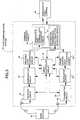
- Fig. 3is a block diagram of a TDMA data communication system showing a first embodiment of the present invention.
- a base station 30communicates with a data communication system 43.
- a receiving antenna 31receives a signal from the base station 30.
- a receiver circuit 32receives a signal from the antenna 31.
- a demodulator circuit 33demodulates a signal supplied from the receiver circuit 32.
- a received data converter circuit 34splits a signal supplied from the demodulator circuit into a received control signal and a received speech/data/video signal (a speach signal, a data signal or a video signal).
- a terminal interface circuit 35includes a speech/data/video terminal data converter circuit 41 and an information transmission rate reduction detector circuit 42.
- a transmission data converter circuit 36adds a control signal to a speech/data/video signal supplied from the terminal interface circuit 35 to form a frame.
- a modulator circuit 37modulates a signal supplied from the transmission data converter circuit 36.
- a transmitter circuit 38transmits a signal supplied from the modulator circuit 37 to the base station 30 via a transmitting antenna 39.
- a timing controller circuit 40controls timing of the data communication system 43.
- a speech/data/video terminal 44transmits and receives signals to communicate with the data communication system 43.
- the terminal 44According to information to be transmitted from the speech/data/video terminal 44, the terminal 44 outputs to the terminal interface circuit 35 a request for the number of channels which the terminal 44 desires to use. This request is inputted to the timing controller circuit 40 via the speech/data/video terminal data converter circuit 41 and the information transmission rate reduction detector circuit 42 of the terminal interface circuit 35, and inputted to the transmission data converter circuit 36 as a control signal.
- the transmission data converter circuit 36adds the control signal to the speech/data/video signal to form a frame.
- the modulator circuit 37the signal supplied from the transmission data converter circuit 36 is modulated by using one of the various modulation methods.
- the signal supplied from the modulator circuit 37is converted in the transmitter circuit 38 to have a desired carrier frequency and transmitted from the transmitting antenna 39 to the base station 30.
- a signal supplied from the base station 30is received by the receiving antenna 31, and converted in the receiver circuit 32 to a base band signal.
- a base band datais demodulated.
- the demodulated base band datais split into a received control signal and a received speech/data/video signal.
- desired informationis obtained.
- the timing controller circuit 40the number of usable channels is detected from the received control signal inputted from the base station 30 via the received data converter circuit 34. The terminal interface circuit 35 is informed of the detected number of usable channels.
- the information transmission rate reduction detector circuit 42 of the terminal interface circuit 35compares the number of channels requested by the speech/data/video terminal 44 with the number of usable channels. If the number of usable channels is insufficient for the requested number of channels, the information transmission rate reduction detector circuit 42 outputs an information transmission rate reduction request signal to the speech/data/video terminal 44.
- the data terminaltransmits a low rate changeover signal of information rate to the terminal interface circuit 35. If, in case of a video terminal, it is desired to transmit images even if the image quality is degraded, 'the video terminal transmits a low rate changeover signal of source encoding rate to the terminal interface circuit 35. On the basis of this changeover signal, the terminal interface circuit 35 transmits information on usable channels.
- Usable channel informationis transmitted from the base station 30 to the data communication system 43 (S1).
- the data communication system 43compares the number of channels to be used with the number of usable channels. If the number of usable channels is insufficient, the data communication system 43 transmits an information transmission rate reduction request or a source encoding rate reduction request to the speech/data/video terminal 44 (S2). If transmission is desired even if it takes time or transmission is desired even if the image quality is degraded, the speech/data/video terminal 44 transmits a low rate changeover signal to the data communication system 43 (S3).
- the data communication system 43receives the low rate changeover signal and transmits a channel request within the number of usable channels (S4).
- the base station 30receives the channel request and transmits permission to use the channels (S5).
- the data communication system 43receives the permission to use the channels and starts communication with the base station 30 (S6).
- the data communication system 43makes a hand over request to another base station, it is now assumed that the number of channels which can be used by another base station is insufficient. In this case as well, the data communication system 43 attempts to reduce failure of hand over due to insufficiency of channels by negotiating for reduction of information transmission rate.
- information of a plurality of channelsis transmitted by assigning a plurality of unit slots.
- Fig. 8is a block diagram of a CDMA data communication system showing a second embodiment of the present invention.
- a base station 80communicates with a data communication system 95.
- a receiving antenna 81receives a signal from the base station 80.
- a receiver circuit 82receives a signal from the antenna 81.
- a despreading circuit 83performs correlation detection on a signal supplied from the receiver circuit 82.
- a demodulator circuit 84demodulates a signal supplied from the despreading circuit 83.
- a received data converter circuit 85splits a signal supplied from the demodulator circuit 84 into a received control signal and a received speech/data/video signal.
- a terminal interface circuit 86includes a speech/data/video terminal data converter circuit 93 and an information transmission rate reduction detector circuit 94.
- a transmission data converter circuit 87adds a control signal to a speech/data/video signal to form a frame.
- a modulator circuit 88modulates a signal supplied from the transmission data converter circuit 87.
- a spreading circuit 89spreads a signal supplied from the modulator circuit 88.
- a transmitter circuit 90transmits a signal supplied from the spreading circuit 89 to the base station 80 via a transmitting antenna 91.
- a timing controller circuit 92controls timing of the data communication system 95.
- a speech/data/video terminal 96transmits and receives signals to communicate with the data communication system 95.
- the terminal 96According to information to be transmitted from the speech/data/video terminal 96, the terminal 96 outputs to the terminal interface circuit 86 a request for the number of channels which the terminal 96 desires to use. This request is inputted to the timing controller circuit 92 via the speech/data/video terminal data converter circuit 93 and the information transmission rate reduction detector circuit 94 of the terminal interface circuit 86, and inputted to the transmission data converter circuit 87 as a control signal.
- the transmission data converter circuit 87adds the control signal to a speech/data/video signal to form a frame.
- the modulator circuit 88the signal is modulated by using one of the various modulation methods.
- a signal supplied from the modulator circuit 88is subjected to code spreading.
- a signal supplied from the spreading circuit 89is then converted in the transmitter circuit 90 to have a desired carrier frequency and transmitted from the transmitting antenna 91 to the base station 80.
- a signal supplied from the base station 80is received by the receiving antenna 81, and converted in the receiver circuit 82 to a base band signal.
- the despreading circuit 83correlation detection is performed.
- the demodulator circuit 84a base band data is demodulated.
- the received data converter circuit 85the demodulated base band data is split into a received control signal and a received speech/data/ video signal.
- desired informationis obtained.
- the timing controller circuit 92the number of usable channels is detected from the received control signal inputted from the base station 80 via the received data converter circuit 85.
- the terminal interface circuit 86is informed of the detected number of usable channels.
- the information transmission rate reduction detector circuit 94 of the terminal interface circuit 86compares the number of channels requested by the speech/data/video terminal 96 with the number of usable channels. If the number of usable channels is insufficient for the requested number of channels, the information transmission rate reduction detector circuit 94 outputs an information transmission rate reduction request signal to the speech/data/video terminal 96.
- the data communication system 95makes hand over request to another base station, it is now assumed that the number of channels which can be used by another base station is insufficient. In this case as well, the data communication system 95 attempts to reduce failure of hand over due to insufficiency of channels by negotiating for reduction of information transmission rate.
- information of a plurality of channelsis transmitted by assigning a plurality of spreading codes.
Landscapes
- Engineering & Computer Science (AREA)
- Signal Processing (AREA)
- Computer Networks & Wireless Communication (AREA)
- Quality & Reliability (AREA)
- Mobile Radio Communication Systems (AREA)
Description
- The present invention relates to a datacommunication system in mobile radio using a TDMA (TimeDivision Multiple Access) method or CDMA (Code DivisionMultiple Access) method.
- Fig. 1 shows the block diagram of aconventional data communication system using the TDMAmethod. On a transmitting side of Fig. 1, a speech ordata signal is inputted to a transmission
data convertercircuit 5 and supplied therein with a control signal andthe like to form a frame. A resultant signal ismodulated in a modulator circuit 6, converted in atransmitter circuit 7 to have a desired carrierfrequency, and transmitted from a transmitting antenna 8to a base station. On a receiving side, a receivingantenna 1 receives a signal from the base station. Areceiver circuit 2 converts the received signal to abase band signal. Ademodulator circuit 3 demodulates abase band data. A receiveddata converter circuit 4splits the base band data into a received control signaland a received speech or data signal, and outputs thereceived speech or data signal. A timing controllercircuit 9 exercises control over every timing andsequence of the data communicattion system. - Fig. 2 shows the block diagram of aconventional data communication system using the CDMAmethod. On a transmitting side of Fig. 2, a speech ordata signal is inputted to a transmission data convertercircuit 16 and supplied therein with a control signaland the like to form a frame. A resultant signal ismodulated in a
modulator circuit 17, spreaded in aspreadingcircuit 18, then converted in atransmittercircuit 19 to have a desired carrier frequency, andtransmitted from a transmittingantenna 20. On areceiving side, a receiving antenna 11 receives a signalfrom a base station. Adespreading circuit 13 performscorrelation detection. Furthermore, ademodulatorcircuit 14 demodulates a base band data. A receiveddata converter circuit 15 splits the base band data intoa received control signal and a received speech or datasignal and outputs the received speech or data signal.Atiming controller circuit 21 exercises control overevery timing and sequence of the data communicattionsystem. - In the TDMA method, however, information whichcan be transmitted on one channel is determined by unitslot. In case data transmission (of high-speed data,image or the like) exceeding a transmission ratedetermined by unit slot is to be performed, transmissionis performed by using a plurality of channelssimultaneously. If the number of usable channels is insufficient when it is desired to use a plurality ofchannels, data cannot be transmitted and call block iscaused. The TDMA method has such a problem. In thecase of the CDMA method as well, data cannot betransmitted and call block is caused in the same waywhen the number of usable channels is insufficient.Furthermore, if the number of usable channels isinsufficient at the time of hand over, hand over in thedata communication system fails.
- The present invention solves such problems ofthe conventional techniques. An object of the presentinvention is to provide an excellent data communicationsystem capable of reducing the probability of callblockage in transmitting data exceeding the number ofusable channels.
- In case the number of usable channels isinsufficient when information such as high speed data orimage is to be transmitted by using a plurality ofchannels, a data communication system according to thepresent invention includes a terminal interface forrequesting to reduce an information transmission rate ora source encoding rate to a speech/data/video terminal(a speach terminal, a data terminal or a video terminal)in order to achieve the above described object.
- In case the number of usable channels isinsufficient, therefore, the probability of callblockage in a speech/data/video terminal can be reducedby reducing the information transmission rate accordingto the present invention. Furthermore, also in case thenumber of usable channels is insufficient at the time ofhand over, hand over failure in the data communicationsystem can be reduced by reducing the informationtransmission rate.
- WO-A-95 07578 relating to an application claimingpriority of September 8, 1993, and published on March 16,1995,i.e. falling under Art. 54(3) EPC,discloses a data communication system provided between abase station and a terminal. Said system comprises amicroprocessor for requesting said terminal to reduce aninformation transmission rate or a source encoding rate whenthe number of usable channels is insufficient at the time oftransmission using a plurality of channels.
- WO-A-87 01254 discloses a data communication systemaccording to the precharacterizing clause of
present claim 3. - Fig. 1 is a block diagram showing theconfiguration of a data communication system using TDMAmethod according to a conventional technique;
- Fig. 2 is a block diagram showing theconfiguration of a data communication system using CDMAmethod according to a conventional technique;
- Fig. 3 is a block diagram showing theconfiguration of a TDMA data communication systemaccording to a first embodiment of the presentinvention;
- Fig. 4 is a diagram showing transmission ofinformation of four channels in one frame;
- Fig. 5 is a diagram showing the number ofchannels of information to be transmitted and the numberof usable channels;
- Fig. 6 is a diagram showing transmission ofinformation of four channels in two frames;
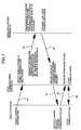
- Fig. 7 is a signal sequence diagram among abase station, a data communication system, and a speech/data/ivideo terminal; and
- Fig. 8 is a block diagram showing theconfiguration of a CDMA data communication systemaccording to a second embodiment of the presentinvention.
- Fig. 3 is a block diagram of a TDMA datacommunication system showing a first embodiment of thepresent invention. In Fig. 3, a
base station 30communicates with adata communication system 43. Areceivingantenna 31 receives a signal from thebasestation 30. Areceiver circuit 32 receives a signalfrom theantenna 31. Ademodulator circuit 33demodulates a signal supplied from thereceiver circuit 32. A receiveddata converter circuit 34 splits asignal supplied from the demodulator circuit into areceived control signal and a received speech/data/videosignal (a speach signal, a data signal or a videosignal). Aterminal interface circuit 35 includes aspeech/data/video terminaldata converter circuit 41 andan information transmission ratereduction detectorcircuit 42. A transmissiondata converter circuit 36adds a control signal to a speech/data/video signal supplied from theterminal interface circuit 35 to forma frame. Amodulator circuit 37 modulates a signalsupplied from the transmissiondata converter circuit 36. Atransmitter circuit 38 transmits a signalsupplied from themodulator circuit 37 to thebasestation 30 via a transmittingantenna 39. Atimingcontroller circuit 40 controls timing of thedatacommunication system 43. A speech/data/video terminal 44 transmits and receives signals to communicate withthedata communication system 43. - Operation of the above described firstembodiment will now be described. According toinformation to be transmitted from the speech/data/
videoterminal 44, theterminal 44 outputs to the terminalinterface circuit 35 a request for the number ofchannels which theterminal 44 desires to use. Thisrequest is inputted to thetiming controller circuit 40via the speech/data/video terminaldata convertercircuit 41 and the information transmission ratereduction detector circuit 42 of theterminal interfacecircuit 35, and inputted to the transmissiondataconverter circuit 36 as a control signal. Thetransmissiondata converter circuit 36 adds the controlsignal to the speech/data/video signal to form a frame.In themodulator circuit 37, the signal supplied fromthe transmissiondata converter circuit 36 is modulatedby using one of the various modulation methods. The signal supplied from themodulator circuit 37 isconverted in thetransmitter circuit 38 to have adesired carrier frequency and transmitted from thetransmittingantenna 39 to thebase station 30. - On a receiving side of the
data communicationsystem 43, a signal supplied from thebase station 30 isreceived by thereceiving antenna 31, and converted inthereceiver circuit 32 to a base band signal. In thedemodulator circuit 33, a base band data is demodulated.In the receiveddata converter circuit 34, thedemodulated base band data is split into a receivedcontrol signal and a received speech/data/video signal.In the speech/data/video terminal 44, desiredinformation is obtained. In thetiming controllercircuit 40, the number of usable channels is detectedfrom the received control signal inputted from thebasestation 30 via the receiveddata converter circuit 34.Theterminal interface circuit 35 is informed of thedetected number of usable channels. The informationtransmission ratereduction detector circuit 42 of theterminal interface circuit 35 compares the number ofchannels requested by the speech/data/video terminal 44with the number of usable channels. If the number ofusable channels is insufficient for the requested numberof channels, the information transmission ratereductiondetector circuit 42 outputs an information transmissionrate reduction request signal to the speech/data/videoterminal 44. - With reference to Fig. 4, it is now assumedthat information of 32 kb/sec can be transmitted in onechannel in the system. In case it is desired totransmit data of 128 kb/sec, it is necessary to use fourchannels. In case the number of usable channels is fouror more on the basis of information supplied from thebase station, transmission of 128 kb/sec (represented byshaded regions) can be made in one frame (10 ms) asshown in Fig. 4. However, in case the number of usablechannels is two on the basis of information suppliedfrom the base station as shown in Fig. 5, transmissionof 128 kb/sec cannot be made in one frame and call blockis caused in case of the conventional data communicationsystem. In the
data communication system 43 of thepresent embodiment, however, the probability of callblockage can be reduced by lowering the informationtransmission rate and performing transmission in twoframes (represented by shaded regions) as shown in Fig.6. - If, in case of a data terminal, changeover toa lower rate and transmission with the lower rate aredesired even if it takes time instead of call block, thedata terminal transmits a low rate changeover signal ofinformation rate to the
terminal interface circuit 35.If, in case of a video terminal, it is desired totransmit images even if the image quality is degraded,'the video terminal transmits a low rate changeoversignal of source encoding rate to theterminal interface circuit 35. On the basis of this changeover signal, theterminal interface circuit 35 transmits information onusable channels. - These operations will now be described byreferring to Fig. 7. Usable channel information istransmitted from the
base station 30 to the datacommunication system 43 (S1). Thedata communicationsystem 43 compares the number of channels to be usedwith the number of usable channels. If the number ofusable channels is insufficient, thedata communicationsystem 43 transmits an information transmission ratereduction request or a source encoding rate reductionrequest to the speech/data/video terminal 44 (S2). Iftransmission is desired even if it takes time ortransmission is desired even if the image quality isdegraded, the speech/data/video terminal 44 transmits alow rate changeover signal to the data communicationsystem 43 (S3). Thedata communication system 43receives the low rate changeover signal and transmits achannel request within the number of usable channels(S4). Thebase station 30 receives the channel requestand transmits permission to use the channels (S5). Thedata communication system 43 receives the permission touse the channels and starts communication with the basestation 30 (S6). - When the
data communication system 43 makes ahand over request to another base station, it is now assumed that the number of channels which can be used byanother base station is insufficient. In this case aswell, thedata communication system 43 attempts toreduce failure of hand over due to insufficiency ofchannels by negotiating for reduction of informationtransmission rate. - Although it has been assumed that a singlebase station and a single terminal are involved in thepresent embodiment, a plurality of base stations and aplurality of terminals may be involved.
- Further, in the TDMA data communication systemaccording to the present embodiment, information of aplurality of channels is transmitted by assigning aplurality of unit slots.
- Fig. 8 is a block diagram of a CDMA datacommunication system showing a second embodiment of thepresent invention. In Fig. 8, a
base station 80communicates with adata communication system 95. Areceivingantenna 81 receives a signal from thebasestation 80. Areceiver circuit 82 receives a signalfrom theantenna 81. Adespreading circuit 83 performscorrelation detection on a signal supplied from thereceiver circuit 82. Ademodulator circuit 84demodulates a signal supplied from thedespreadingcircuit 83. A receiveddata converter circuit 85 splits a signal supplied from thedemodulator circuit 84 into areceived control signal and a received speech/data/videosignal. A terminal interface circuit 86 includes aspeech/data/video terminaldata converter circuit 93 andan information transmission ratereduction detectorcircuit 94. A transmissiondata converter circuit 87adds a control signal to a speech/data/video signal toform a frame. Amodulator circuit 88 modulates a signalsupplied from the transmissiondata converter circuit 87. A spreadingcircuit 89 spreads a signal suppliedfrom themodulator circuit 88. Atransmitter circuit 90transmits a signal supplied from the spreadingcircuit 89 to thebase station 80 via a transmittingantenna 91.Atiming controller circuit 92 controls timing of thedata communication system 95. A speech/data/videoterminal 96 transmits and receives signals tocommunicate with thedata communication system 95. - Operation of the above described secondembodiment will now be described. According toinformation to be transmitted from the speech/data/
videoterminal 96, the terminal 96 outputs to the terminalinterface circuit 86 a request for the number ofchannels which the terminal 96 desires to use. Thisrequest is inputted to thetiming controller circuit 92via the speech/data/video terminaldata convertercircuit 93 and the information transmission ratereduction detector circuit 94 of the terminal interface circuit 86, and inputted to the transmissiondataconverter circuit 87 as a control signal. Thetransmissiondata converter circuit 87 adds the controlsignal to a speech/data/video signal to form a frame.In themodulator circuit 88, the signal is modulated byusing one of the various modulation methods. In thespreadingcircuit 89, a signal supplied from themodulator circuit 88 is subjected to code spreading. Asignal supplied from the spreadingcircuit 89 is thenconverted in thetransmitter circuit 90 to have adesired carrier frequency and transmitted from thetransmittingantenna 91 to thebase station 80. - On a receiving side of the
data communicationsystem 95, a signal supplied from thebase station 80 isreceived by the receivingantenna 81, and converted inthereceiver circuit 82 to a base band signal. In thedespreading circuit 83, correlation detection isperformed. In thedemodulator circuit 84, a base banddata is demodulated. In the receiveddata convertercircuit 85, the demodulated base band data is split intoa received control signal and a received speech/data/video signal. In the speech/data/video terminal 96,desired information is obtained. In thetimingcontroller circuit 92, the number of usable channels isdetected from the received control signal inputted fromthebase station 80 via the receiveddata convertercircuit 85. The terminal interface circuit 86 is informed of the detected number of usable channels. Theinformation transmission ratereduction detector circuit 94 of the terminal interface circuit 86 compares thenumber of channels requested by the speech/data/videoterminal 96 with the number of usable channels. If thenumber of usable channels is insufficient for therequested number of channels, the informationtransmission ratereduction detector circuit 94 outputsan information transmission rate reduction requestsignal to the speech/data/video terminal 96. - When the
data communication system 95 makeshand over request to another base station, it is nowassumed that the number of channels which can be used byanother base station is insufficient. In this case aswell, thedata communication system 95 attempts toreduce failure of hand over due to insufficiency ofchannels by negotiating for reduction of informationtransmission rate. - Although it has been assumed that a singlebase station and a single terminal are involved in thepresent embodiment, a plurality of base stations and aplurality of terminals may be involved.
- Further, in the CDMA data communication systemaccording to the present embodiment, information of aplurality of channels is transmitted by assigning aplurality of spreading codes.
Claims (6)
- A data communication system (43; 95) provided between abase station (30; 80) and a terminal (44; 96), and comprising:a terminal interface (35; 86) for requesting saidterminal (44; 96) to reduce an information transmission rateor a source encoding rate when the number of usable channelsis insufficient at the time of transmission using a pluralityof channels or at the time of hand over;a receive data converter circuit (34; 85) for receiving afirst signal from said base station (30; 80) and for splittingthe first signal into a received control signal and an outputsignal to be outputted to said terminal (44; 96); anda transmission data converter circuit (36; 87) forreceiving a second signal from said terminal (44; 96) and foradding a transmitting control signal to the second signal.
- A data communication system (43; 95) according to claim1,characterized in that
in case said terminal (44; 96) is a video terminal, saidterminal interface (35; 86) requests said terminal (44; 96) toreduce said source encoding rate. - A data communication system (43; 95) provided between abase station (30; 80) and a terminal (44; 96), and comprising:
a terminal interface circuit (35; 86) for being suppliedfrom said terminal (44; 96) the first number of channels to be used for transmitting an information or the second number ofchannels to be needed at the time of hand over and for beingsupplied from said base station (30; 80) the third number ofusable channels;
characterized by
an information transmission rate reduction detectorcircuit (42; 94) included in said terminal interface circuit(35; 86) for comparing said first number of channels or saidsecond number of channels with said third number of usablechannels and for requesting said terminal (44; 96) to reducean information transmission rate or a source encoding ratewhen said third number of usable channels is insufficient. - A data communication system (43; 95) according to claim3,characterized in that
in case said terminal (44; 96) is a video terminal, saidinformation transmission rate reduction detector circuit (42;94) requests said terminal (44; 96) to reduce said sourceencoding rate. - A data communication system (43; 95) according to any oneof claim 1 to 4,characterized in that
an information transmitted over a plurality of channelsis transmitted by assigning simultaneously a plurality of timeslots. - A data communication system (43; 95) according to any oneof claims 1 to 4,characterized in that
an information transmitted over a plurality of channelsis transmitted by assigning simultaneously a plurality ofspreading codes.
Applications Claiming Priority (3)
| Application Number | Priority Date | Filing Date | Title |
|---|---|---|---|
| JP20950/94 | 1994-02-18 | ||
| JP2095094 | 1994-02-18 | ||
| JP02095094AJP3260950B2 (en) | 1994-02-18 | 1994-02-18 | Data communication device |
Publications (2)
| Publication Number | Publication Date |
|---|---|
| EP0668669A1 EP0668669A1 (en) | 1995-08-23 |
| EP0668669B1true EP0668669B1 (en) | 2001-10-31 |
Family
ID=12041477
Family Applications (1)
| Application Number | Title | Priority Date | Filing Date |
|---|---|---|---|
| EP95102288AExpired - LifetimeEP0668669B1 (en) | 1994-02-18 | 1995-02-17 | Data communication system controlling the information transmission bit rate or source encoding rate |
Country Status (4)
| Country | Link |
|---|---|
| US (1) | US5598416A (en) |
| EP (1) | EP0668669B1 (en) |
| JP (1) | JP3260950B2 (en) |
| DE (1) | DE69523491T2 (en) |
Families Citing this family (45)
| Publication number | Priority date | Publication date | Assignee | Title |
|---|---|---|---|---|
| JPH08235049A (en)* | 1995-02-27 | 1996-09-13 | Nec Corp | Communication system |
| JP3658087B2 (en)* | 1995-07-04 | 2005-06-08 | キヤノン株式会社 | Terminal device and method for controlling terminal device |
| US6252898B1 (en)* | 1995-07-19 | 2001-06-26 | Hitachi Denshi Kabushiki Kaisha | Spread spectrum communication method and system wherein data rate of data to be transmitted is changed in accordance with transmission quality |
| FI101337B1 (en)* | 1995-09-25 | 1998-05-29 | Nokia Telecommunications Oy | Mobile telephony system and method for connecting a data call |
| US5734646A (en)* | 1995-10-05 | 1998-03-31 | Lucent Technologies Inc. | Code division multiple access system providing load and interference based demand assignment service to users |
| US5907555A (en)* | 1995-10-18 | 1999-05-25 | Telefonaktiebolaget Lm Ericsson | Method for compensating for time dispersion in a communication system |
| FI100567B (en)* | 1996-01-08 | 1997-12-31 | Nokia Telecommunications Oy | Power adapter and data transmission procedure in mobile telephone networks |
| US5726983A (en)* | 1996-08-09 | 1998-03-10 | Motorola, Inc. | Communication device with variable frame processing time |
| GB2357015B (en)* | 1997-01-08 | 2001-08-15 | Nec Technologies | Combining cordless and mobile telephone operation |
| FI106666B (en) | 1997-01-24 | 2001-03-15 | Nokia Networks Oy | Power control procedure for discontinuous transmissions |
| US5771229A (en)* | 1997-01-31 | 1998-06-23 | Motorola, Inc. | Method, system and mobile communication unit for communicating over multiple channels in a wireless communication system |
| US6009473A (en)* | 1997-04-30 | 1999-12-28 | Oracle Corporation | Using callbacks to effectively manage resources |
| US6081536A (en) | 1997-06-20 | 2000-06-27 | Tantivy Communications, Inc. | Dynamic bandwidth allocation to transmit a wireless protocol across a code division multiple access (CDMA) radio link |
| US6542481B2 (en) | 1998-06-01 | 2003-04-01 | Tantivy Communications, Inc. | Dynamic bandwidth allocation for multiple access communication using session queues |
| US6226279B1 (en) | 1997-10-22 | 2001-05-01 | Telefonaktiebolaget L M Ericsson (Publ) | Allowing several multiple access schemes for packet data in a digital cellular communication system |
| CA2273981C (en)* | 1997-12-10 | 2003-07-08 | Mitsubishi Denki Kabushiki Kaisha | Mobile communication system |
| WO1999031823A1 (en)* | 1997-12-16 | 1999-06-24 | Mitsubishi Denki Kabushiki Kaisha | Method for allocating radio channel for radio communication |
| US6222832B1 (en)* | 1998-06-01 | 2001-04-24 | Tantivy Communications, Inc. | Fast Acquisition of traffic channels for a highly variable data rate reverse link of a CDMA wireless communication system |
| US7394791B2 (en)* | 1997-12-17 | 2008-07-01 | Interdigital Technology Corporation | Multi-detection of heartbeat to reduce error probability |
| US8175120B2 (en)* | 2000-02-07 | 2012-05-08 | Ipr Licensing, Inc. | Minimal maintenance link to support synchronization |
| US7936728B2 (en)* | 1997-12-17 | 2011-05-03 | Tantivy Communications, Inc. | System and method for maintaining timing of synchronization messages over a reverse link of a CDMA wireless communication system |
| US7079523B2 (en)* | 2000-02-07 | 2006-07-18 | Ipr Licensing, Inc. | Maintenance link using active/standby request channels |
| US7496072B2 (en)* | 1997-12-17 | 2009-02-24 | Interdigital Technology Corporation | System and method for controlling signal strength over a reverse link of a CDMA wireless communication system |
| US9525923B2 (en) | 1997-12-17 | 2016-12-20 | Intel Corporation | Multi-detection of heartbeat to reduce error probability |
| GB2332820A (en)* | 1997-12-23 | 1999-06-30 | Northern Telecom Ltd | cOMMUNICATION SYSTEM HAVING A REDUCED DATA RATE FOR HIGH TRAFFIC LEVELS |
| KR100257884B1 (en) | 1998-05-14 | 2000-06-01 | 김영환 | Improvement of Trunk Transmission Efficiency between Control Station and Base Station in Digital Mobile Communication System |
| US6611503B1 (en) | 1998-05-22 | 2003-08-26 | Tandberg Telecom As | Method and apparatus for multimedia conferencing with dynamic bandwidth allocation |
| US7773566B2 (en)* | 1998-06-01 | 2010-08-10 | Tantivy Communications, Inc. | System and method for maintaining timing of synchronization messages over a reverse link of a CDMA wireless communication system |
| US7221664B2 (en)* | 1998-06-01 | 2007-05-22 | Interdigital Technology Corporation | Transmittal of heartbeat signal at a lower level than heartbeat request |
| US8134980B2 (en)* | 1998-06-01 | 2012-03-13 | Ipr Licensing, Inc. | Transmittal of heartbeat signal at a lower level than heartbeat request |
| US7027484B1 (en) | 1998-07-10 | 2006-04-11 | Qualcomm Incorporated | Method and apparatus for transmitting and receiving high speed data using code division multiple access channels |
| US6798736B1 (en)* | 1998-09-22 | 2004-09-28 | Qualcomm Incorporated | Method and apparatus for transmitting and receiving variable rate data |
| EP1024676A1 (en)* | 1999-01-31 | 2000-08-02 | TELEFONAKTIEBOLAGET LM ERICSSON (publ) | Communication system, methods of managing a communication system and mobile user equipment |
| US6873597B1 (en)* | 1999-08-11 | 2005-03-29 | Nortel Networks Limited | Reduced data rate communication system |
| US6741577B1 (en)* | 1999-11-29 | 2004-05-25 | Koninklijke Philips Electronics N.V. | Inter-frequency handover in wireless CDMA systems |
| US8155096B1 (en) | 2000-12-01 | 2012-04-10 | Ipr Licensing Inc. | Antenna control system and method |
| US6954448B2 (en) | 2001-02-01 | 2005-10-11 | Ipr Licensing, Inc. | Alternate channel for carrying selected message types |
| US7551663B1 (en)* | 2001-02-01 | 2009-06-23 | Ipr Licensing, Inc. | Use of correlation combination to achieve channel detection |
| CA2867406C (en) | 2001-06-13 | 2016-08-02 | Intel Corporation | Transmittal of heartbeat signal at a lower level than heartbeat request |
| US7948887B2 (en)* | 2008-06-24 | 2011-05-24 | Microsoft Corporation | Network bandwidth measurement |
| US10836483B2 (en) | 2009-09-11 | 2020-11-17 | Aerovironment, Inc. | Ad hoc dynamic data link repeater |
| US9084276B2 (en) | 2009-09-11 | 2015-07-14 | Aerovironment, Inc. | Dynamic transmission control for a wireless network |
| JP4965682B2 (en)* | 2010-04-05 | 2012-07-04 | 株式会社エヌ・ティ・ティ・ドコモ | Radio communication system, radio control apparatus, radio base station, and radio communication method |
| WO2017015310A2 (en) | 2015-07-20 | 2017-01-26 | Aerovironment, Inc. | Ad hoc dynamic data link repeater |
| CN110611789A (en)* | 2018-06-14 | 2019-12-24 | 杭州海康威视数字技术股份有限公司 | Video streaming transmission control method and device, electronic equipment and storage medium |
Citations (1)
| Publication number | Priority date | Publication date | Assignee | Title |
|---|---|---|---|---|
| WO1995007578A1 (en)* | 1993-09-08 | 1995-03-16 | Qualcomm Incorporated | Method and apparatus for determining the transmission data rate in a multi-user communication system |
Family Cites Families (14)
| Publication number | Priority date | Publication date | Assignee | Title |
|---|---|---|---|---|
| IL79775A (en)* | 1985-08-23 | 1990-06-10 | Republic Telcom Systems Corp | Multiplexed digital packet telephone system |
| US4701943A (en)* | 1985-12-31 | 1987-10-20 | Motorola, Inc. | Paging system using LPC speech encoding with an adaptive bit rate |
| AU5589086A (en)* | 1986-03-25 | 1987-10-20 | Motorola, Inc. | Method and apparatus for controlling a tdm communication device |
| JPH01117439A (en)* | 1987-10-30 | 1989-05-10 | Nec Corp | Data communication system |
| JPH02274131A (en)* | 1989-04-17 | 1990-11-08 | Toshiba Corp | Transmission control method for mobile radio communication system |
| CA2038646C (en)* | 1990-03-20 | 1995-02-07 | Katsumi Oomuro | Atm communication system with optimal traffic control by changing the allocated bandwidth |
| US5115429A (en)* | 1990-08-02 | 1992-05-19 | Codex Corporation | Dynamic encoding rate control minimizes traffic congestion in a packet network |
| NZ239283A (en)* | 1990-08-23 | 1994-09-27 | Ericsson Telefon Ab L M | Mobile cellular radio: handoff between half rate and full rate channels according to estimated received signal quality |
| US5115309A (en)* | 1990-09-10 | 1992-05-19 | At&T Bell Laboratories | Method and apparatus for dynamic channel bandwidth allocation among multiple parallel video coders |
| US5231649A (en)* | 1991-08-08 | 1993-07-27 | Ascend Communications, Inc. | Method and apparatus for dynamic bandwidth allocation in a digital communication session |
| DE69125370T2 (en)* | 1991-08-28 | 1997-08-14 | Alcatel Bell Nv | Coding arrangement |
| US5321721A (en)* | 1991-09-13 | 1994-06-14 | Sony Corporation | Spread spectrum communication system and transmitter-receiver |
| JPH05167549A (en)* | 1991-12-16 | 1993-07-02 | Mitsubishi Electric Corp | Control information transmission method in time division multiplex communication system |
| IT1270938B (en)* | 1993-05-14 | 1997-05-16 | Cselt Centro Studi Lab Telecom | PROCEDURE FOR THE CONTROL OF THE TRANSMISSION ON A SAME CHANNEL OF INFORMATION FLOWS AT VARIABLE SPEED IN COMMUNICATION SYSTEMS BETWEEN MOBILE VEHICLES, AND A SYSTEM USING SUCH PROCEDURE |
- 1994
- 1994-02-18JPJP02095094Apatent/JP3260950B2/ennot_activeExpired - Lifetime
- 1995
- 1995-02-10USUS08/386,463patent/US5598416A/ennot_activeExpired - Lifetime
- 1995-02-17EPEP95102288Apatent/EP0668669B1/ennot_activeExpired - Lifetime
- 1995-02-17DEDE69523491Tpatent/DE69523491T2/ennot_activeExpired - Lifetime
Patent Citations (1)
| Publication number | Priority date | Publication date | Assignee | Title |
|---|---|---|---|---|
| WO1995007578A1 (en)* | 1993-09-08 | 1995-03-16 | Qualcomm Incorporated | Method and apparatus for determining the transmission data rate in a multi-user communication system |
Also Published As
| Publication number | Publication date |
|---|---|
| JP3260950B2 (en) | 2002-02-25 |
| DE69523491D1 (en) | 2001-12-06 |
| JPH07231479A (en) | 1995-08-29 |
| EP0668669A1 (en) | 1995-08-23 |
| US5598416A (en) | 1997-01-28 |
| DE69523491T2 (en) | 2002-05-23 |
Similar Documents
| Publication | Publication Date | Title |
|---|---|---|
| EP0668669B1 (en) | Data communication system controlling the information transmission bit rate or source encoding rate | |
| EP0665659B1 (en) | TDMA-CDMA mobile communication system | |
| EP2094040B1 (en) | Method and apparatus for providing service negotiation in a mobile communication system | |
| AU753880B2 (en) | Dedicated control channel handoff in CDMA communication system | |
| EP1157487B1 (en) | Data transmitting method in a cdma system | |
| US9363759B2 (en) | Power control protocol for highly variable data rate reverse link of a wireless communication system | |
| US7421283B2 (en) | Transmission power control method and apparatus for mobile communication system | |
| EP0809365B1 (en) | Scheme for controlling transmission powers during soft handover in a cdma mobile communication system | |
| US7006463B2 (en) | CDMA communication system and its transmission power control method | |
| KR0153030B1 (en) | Wireless communication system and signal communication method | |
| EP0851612B1 (en) | Signal transmitting method, mobile station device, and base station device for cdma mobile communication system | |
| CA2137386C (en) | Time division multiple access mobile wireless telecommunication system | |
| AU3496897A (en) | Cdma communication system which selectively suppresses data transmissions during establishment of a communication channel | |
| US6914889B1 (en) | Variable rate forward power control for multichannel applications | |
| EP0991204B1 (en) | A transmission power control method using a pilot symbol pattern | |
| US6252898B1 (en) | Spread spectrum communication method and system wherein data rate of data to be transmitted is changed in accordance with transmission quality | |
| US5930246A (en) | Bidirectional communication system | |
| US5850394A (en) | CDMA communications system using multiplexed signaling data lines | |
| JP3045937B2 (en) | Data communication device | |
| US6073022A (en) | Radio channel initial transmission scheme for mobile communication system | |
| JP3561496B2 (en) | Data communication device | |
| KR100340029B1 (en) | Power control method of packet service using channel shared with RIU and RP in W-CMDA WLL | |
| JP2984216B2 (en) | Spread spectrum communication method and apparatus | |
| KR20000020588A (en) | Method for controlling power for reverse traffic preamble in mobile communication system | |
| HK1002722A1 (en) | Method of access in trunked communications system |
Legal Events
| Date | Code | Title | Description |
|---|---|---|---|
| PUAI | Public reference made under article 153(3) epc to a published international application that has entered the european phase | Free format text:ORIGINAL CODE: 0009012 | |
| 17P | Request for examination filed | Effective date:19950217 | |
| AK | Designated contracting states | Kind code of ref document:A1 Designated state(s):DE FR GB | |
| 17Q | First examination report despatched | Effective date:19990520 | |
| GRAG | Despatch of communication of intention to grant | Free format text:ORIGINAL CODE: EPIDOS AGRA | |
| GRAG | Despatch of communication of intention to grant | Free format text:ORIGINAL CODE: EPIDOS AGRA | |
| GRAH | Despatch of communication of intention to grant a patent | Free format text:ORIGINAL CODE: EPIDOS IGRA | |
| GRAH | Despatch of communication of intention to grant a patent | Free format text:ORIGINAL CODE: EPIDOS IGRA | |
| GRAA | (expected) grant | Free format text:ORIGINAL CODE: 0009210 | |
| AK | Designated contracting states | Kind code of ref document:B1 Designated state(s):DE FR GB | |
| REF | Corresponds to: | Ref document number:69523491 Country of ref document:DE Date of ref document:20011206 | |
| REG | Reference to a national code | Ref country code:GB Ref legal event code:IF02 | |
| PLBE | No opposition filed within time limit | Free format text:ORIGINAL CODE: 0009261 | |
| STAA | Information on the status of an ep patent application or granted ep patent | Free format text:STATUS: NO OPPOSITION FILED WITHIN TIME LIMIT | |
| 26N | No opposition filed | ||
| PGFP | Annual fee paid to national office [announced via postgrant information from national office to epo] | Ref country code:FR Payment date:20140211 Year of fee payment:20 | |
| PGFP | Annual fee paid to national office [announced via postgrant information from national office to epo] | Ref country code:GB Payment date:20140212 Year of fee payment:20 | |
| REG | Reference to a national code | Ref country code:GB Ref legal event code:732E Free format text:REGISTERED BETWEEN 20140612 AND 20140618 | |
| REG | Reference to a national code | Ref country code:DE Ref legal event code:R082 Ref document number:69523491 Country of ref document:DE Representative=s name:LEINWEBER & ZIMMERMANN, DE | |
| REG | Reference to a national code | Ref country code:DE Ref legal event code:R082 Ref document number:69523491 Country of ref document:DE Representative=s name:LEINWEBER & ZIMMERMANN, DE Effective date:20140711 Ref country code:DE Ref legal event code:R081 Ref document number:69523491 Country of ref document:DE Owner name:PANASONIC INTELLECTUAL PROPERTY CORPORATION OF, US Free format text:FORMER OWNER: PANASONIC CORPORATION, KADOMA-SHI, OSAKA, JP Effective date:20140711 | |
| REG | Reference to a national code | Ref country code:FR Ref legal event code:TP Owner name:PANASONIC INTELLECTUAL PROPERTY CORPORATION OF, US Effective date:20140722 | |
| PGFP | Annual fee paid to national office [announced via postgrant information from national office to epo] | Ref country code:DE Payment date:20140417 Year of fee payment:20 | |
| REG | Reference to a national code | Ref country code:DE Ref legal event code:R071 Ref document number:69523491 Country of ref document:DE | |
| REG | Reference to a national code | Ref country code:GB Ref legal event code:PE20 Expiry date:20150216 | |
| PG25 | Lapsed in a contracting state [announced via postgrant information from national office to epo] | Ref country code:GB Free format text:LAPSE BECAUSE OF EXPIRATION OF PROTECTION Effective date:20150216 |