EP0668143B1 - Dual flexible lip extrusion apparatus - Google Patents
Dual flexible lip extrusion apparatusDownload PDFInfo
- Publication number
- EP0668143B1 EP0668143B1EP94112554AEP94112554AEP0668143B1EP 0668143 B1EP0668143 B1EP 0668143B1EP 94112554 AEP94112554 AEP 94112554AEP 94112554 AEP94112554 AEP 94112554AEP 0668143 B1EP0668143 B1EP 0668143B1
- Authority
- EP
- European Patent Office
- Prior art keywords
- lip
- die
- lips
- adjustment block
- extrusion apparatus
- Prior art date
- Legal status (The legal status is an assumption and is not a legal conclusion. Google has not performed a legal analysis and makes no representation as to the accuracy of the status listed.)
- Expired - Lifetime
Links
Images


Classifications
- B—PERFORMING OPERATIONS; TRANSPORTING
- B29—WORKING OF PLASTICS; WORKING OF SUBSTANCES IN A PLASTIC STATE IN GENERAL
- B29C—SHAPING OR JOINING OF PLASTICS; SHAPING OF MATERIAL IN A PLASTIC STATE, NOT OTHERWISE PROVIDED FOR; AFTER-TREATMENT OF THE SHAPED PRODUCTS, e.g. REPAIRING
- B29C48/00—Extrusion moulding, i.e. expressing the moulding material through a die or nozzle which imparts the desired form; Apparatus therefor
- B29C48/25—Component parts, details or accessories; Auxiliary operations
- B29C48/30—Extrusion nozzles or dies
- B29C48/305—Extrusion nozzles or dies having a wide opening, e.g. for forming sheets
- B29C48/31—Extrusion nozzles or dies having a wide opening, e.g. for forming sheets being adjustable, i.e. having adjustable exit sections
- B29C48/313—Extrusion nozzles or dies having a wide opening, e.g. for forming sheets being adjustable, i.e. having adjustable exit sections by positioning the die lips
- B—PERFORMING OPERATIONS; TRANSPORTING
- B29—WORKING OF PLASTICS; WORKING OF SUBSTANCES IN A PLASTIC STATE IN GENERAL
- B29C—SHAPING OR JOINING OF PLASTICS; SHAPING OF MATERIAL IN A PLASTIC STATE, NOT OTHERWISE PROVIDED FOR; AFTER-TREATMENT OF THE SHAPED PRODUCTS, e.g. REPAIRING
- B29C48/00—Extrusion moulding, i.e. expressing the moulding material through a die or nozzle which imparts the desired form; Apparatus therefor
- B29C48/03—Extrusion moulding, i.e. expressing the moulding material through a die or nozzle which imparts the desired form; Apparatus therefor characterised by the shape of the extruded material at extrusion
- B29C48/07—Flat, e.g. panels
- B29C48/08—Flat, e.g. panels flexible, e.g. films
- B—PERFORMING OPERATIONS; TRANSPORTING
- B29—WORKING OF PLASTICS; WORKING OF SUBSTANCES IN A PLASTIC STATE IN GENERAL
- B29C—SHAPING OR JOINING OF PLASTICS; SHAPING OF MATERIAL IN A PLASTIC STATE, NOT OTHERWISE PROVIDED FOR; AFTER-TREATMENT OF THE SHAPED PRODUCTS, e.g. REPAIRING
- B29C48/00—Extrusion moulding, i.e. expressing the moulding material through a die or nozzle which imparts the desired form; Apparatus therefor
- B29C48/25—Component parts, details or accessories; Auxiliary operations
- B29C48/92—Measuring, controlling or regulating
- B—PERFORMING OPERATIONS; TRANSPORTING
- B29—WORKING OF PLASTICS; WORKING OF SUBSTANCES IN A PLASTIC STATE IN GENERAL
- B29C—SHAPING OR JOINING OF PLASTICS; SHAPING OF MATERIAL IN A PLASTIC STATE, NOT OTHERWISE PROVIDED FOR; AFTER-TREATMENT OF THE SHAPED PRODUCTS, e.g. REPAIRING
- B29C2948/00—Indexing scheme relating to extrusion moulding
- B29C2948/92—Measuring, controlling or regulating
- B29C2948/92504—Controlled parameter
- B29C2948/92609—Dimensions
- B29C2948/92647—Thickness
- B—PERFORMING OPERATIONS; TRANSPORTING
- B29—WORKING OF PLASTICS; WORKING OF SUBSTANCES IN A PLASTIC STATE IN GENERAL
- B29C—SHAPING OR JOINING OF PLASTICS; SHAPING OF MATERIAL IN A PLASTIC STATE, NOT OTHERWISE PROVIDED FOR; AFTER-TREATMENT OF THE SHAPED PRODUCTS, e.g. REPAIRING
- B29C2948/00—Indexing scheme relating to extrusion moulding
- B29C2948/92—Measuring, controlling or regulating
- B29C2948/92819—Location or phase of control
- B29C2948/92857—Extrusion unit
- B29C2948/92904—Die; Nozzle zone
Definitions
- the present inventionrelates to an extrusion apparatus for extruding a single stream of thermoplastic material according to the precharacterising part of claim 1.
- Dies for extruding thermoplastic materialtypically include a pair of die portions joined together to define an outlet through which molten thermoplastic material is extruded.
- each die portionincludes a lip, and the lips of the two die portions cooperate to define a die outlet or lip gap.
- the lipsare integral with the die portions and a first one of the lips is joined to a respective die portion by a flexible hinge.
- Apparatusis provided to adjust the position of the first lip and thus the width of the lip gap.
- the adjustment apparatusincludes a plurality of thermally responsive members spaced along the width of the die and a plurality of heater elements each disposed in heat-transfer relationship with a thermally responsive member. The heater elements are individually controlled to adjust the profile of the lip gap at one edge thereof.
- a manually operable adjustment apparatusmay be provided to adjust the width of the lip gap. In either case, the adjustability of the die is limited by the deflection limit of the flexible hinge. Also, the initial set-up procedure to preset the desired outlet width can be undesirably time consuming.
- first and second die lip membersare separate from and carried by respective die portions.
- the first die lip memberis rigidly secured to the die body while a second die lip member is mounted for sliding movement relative to the first die lip member.
- adjustment apparatusis provided for positioning the second die lip member so that a desired lip gap width is achieved and maintained. While this die design has a wide adjustment range, changing of the gap width can be a lengthy process and gauge control capability is limited.
- a third prior art extrusion dieincludes first and second die body portions, one having a first lip coupled integrally therewith by a flexible hinge and the other having a second, removable lip bolted thereto.
- a plurality of thermally responsive membersare coupled to the first lip for adjusting the position of that lip to achieve a desired extrudate profile.
- the removable lipon the other hand, is stationary but can be replaced by other lip members having different dimensions so that the base lip gap can be selected as desired or necessary.
- This diehas relatively good gauge control compared with other prior art die designs but requires a longer time to change the base lip gap and thus has a longer product changeover time.
- Document GB-A-2 028 228discloses an extrusion die, comprising first and second die body portions, each having a main body and a lip interconnected to the main body, wherein the die body portions are joined such that a single die outlet is formed between and bounded by the lips and irst and second moving means coupled to the first and second die body portions for moving the lips to adjust the die outlet.
- EP-A-0 456 176discloses an extrusion apparatus having a mechanism for thermally-controlled lip gap adjustment.
- the apparatusincludes a flow path for a gaseous cooling medium in which flow path a plurality of temperature-responsive adjustment members are disposed.
- US-A-3 380 610discloses an extrusion apparatus for rubber products, whereby the die opening is adjusted by measuring the configuration and then comparing the measured results with a standard configuration.
- US-A-1 422 356discloses an extrusion apparatus whereby the die opening may be adjusted from time to time by using specific die plates according to requirement.
- the inventionrelates to a device as per GB-A-2 028 228, which forms the preamble of claim 1 on file.
- US-A-3 264 686relates to the same type of equipment, i.e. an extrusion apparatus for extruding of a stream of plastic material. Also, there are two lips forming an outlet. Still further, there are means for adjusting the said outlet to thereby control the thickness of the stream of plastic material.
- This documentcomprises differences, which are significant. Those differences are as follows: While the extrusion apparatus as per the invention comprises a separate lip adjustment block which provides for a deformation of the lip, there is no such lip adjustment block to be found in the document. Instead, with the known device, the lip is formed by the said jaw 14 respectively 10 as outlined above. Further, the extrusion apparatus as per the invention comprises a hinge. Such hinge allows deformation of body portions carrying the lips. There is no such hinge with the document, and accordingly, there is no deformation. Instead, jaw 10 respectively 14 just make a simple movement without any deformation.
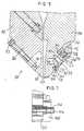
- a prior art extrusion die 20includes first and second die body portions 22, 24 having respective lips 26, 28.
- the first and second die body portions 22, 24are joined together in any conventional manner, for example by body bolts (not shown), such that a die outlet 30 is formed between and defined by the lips 26, 28.
- the lips 26, 28are integral with the die body portions 22, 24, respectively, and the lip 26 is interconnected with a main body 32 of the die body portion 22 by a hinge 34.
- a number of thermally expandable bolts 36are coupled between the main body 32 and the lip 26 of the die body portion 22 for moving the lip 26 relative to the lip 28 to adjust the die outlet 30.
- a plurality of heatersare disposed in heat-transfer relationship with the bolts 36 and are controlled so that the die outlet 30 has a predetermined profile corresponding to the desired dimensions of the material to be extruded. Due to the limited flexibility of the hinge 34, however, this type of die, called a flex-lip die, can produce only a limited range of extrudate thicknesses. Moreover, this design requires a long time to preset the required gap dimensions.
- another prior art extrusion die 40includes first and second die body portions 42, 44 and lip members 46, 48 coupled to the die body portions 42, 44, respectively.
- the die body portions 42, 44are joined such that a die outlet 50 is formed between the lip portions 46, 48.
- One lip member 46is capable of sliding in a horizontal direction (as shown in Fig. 2) relative to the other lip member 48, which is bolted in place and thus remains stationary, in order to vary the dimensions of the die outlet 50. While this so-called sliding lip die has a wider operating range than the flex-lip die of Fig. 1, the sliding lip die requires a long time to change the dimensions of the die outlet 50. Moreover, this is a cumbersome die design that offers little flexibility and only limited gauge control capability.
- a third prior art extrusion apparatus 60includes first and second die body portions 62, 64.
- the die body portion 62includes a main body 66, a lip 68, and a hinge 70 interconnecting the main body 66 and the lip 68.
- the die body portion 64includes a main body 72 and a lip member 74 secured to the main body 72 by a plurality of bolts 76 (only one of which is shown in Fig. 3).
- the die body portions 62, 64are joined such that a die outlet 78 is formed between and defined by the lip 68 and the lip member 74.
- Thermally expandable bolts 80 coupled between the main body 66 and the lip 68are operable to move the lip 68 to adjust the die outlet 78.
- the lip member 74may be removed from the main body 72 of the die body portion 64 by unscrewing bolts 76, one of which is shown in Fig 3. A different lip member 74 may be attached to the main body 72 by the bolts 76 so that a different configuration or lip gap for the die outlet 78 is obtained.
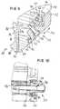
- an extrusion apparatus 100 in accordance with the present inventionincludes first and second die body portions 102, 104.
- the die body portion 102includes a main body 106, a lip 108, and a hinge 110 interconnecting the lip 108 with the main body 106.
- the die body portion 104includes a main body 112, a lip 114, and a hinge 116 interconnecting the lip 114 with the main body 112.
- the die body portions 102, 104are joined by body bolts (not shown) such that a single die outlet 120 is formed between and bounded by the lips 108, 114.
- Mechanically adjustable bolts 122are coupled between the main body 106 and the lip 108 for moving the lip 108 bidirectionally to precisely adjust the dimensions of the die outlet 120.
- the bolts 122may be thermally expandable and a series of heaters (not shown) may be automatically controlled to adjust the dimensions of the die outlet 120 as disclosed in Nissel U.S. Patent No. 3,940,221, the disclosure of which is hereby incorporated herein by reference.
- apparatus 124is provided for moving the lip 114 to further adjust the die outlet 120.
- a sliding angle member 126 having one or more angled cam blocks 128 extending therefromis disposed closely within a longitudinally extending recess 130 in the die body portion 112.
- a lip adjustment block 132is adjustably secured by a series of shouldered bolts 134 (one of which is shown in Fig. 5) to the main body 112. More specifically, each shouldered bolt 134 is disposed in an elongated slot 136 in the lip adjustment block 132 and is threaded into a corresponding bore 137 in the main body 112.
- Each slot 136is sized relative to the bolt 134 located therein such that the shouldered bolts 134 hold the block 132 against the main body 112, and the block 132 is movable up and down but not in and out (as shown in Fig. 5).
- the block 132may be located in any desired position relative to the main body 112.
- a flange 138 carried by the lip 114extends the full width of the die body portion 104 and is snugly disposed in a complementarily shaped groove or recess 140 formed in a marginal portion 142 extending the full width of the lip adjustment block 132. It should be noted that the flange 138 and the complementary groove 140 need not extend along the full width of the die body portion 104 as shown in Fig.
- the lip adjustment block 132may, in fact, be coupled to the lip 114 in any conventional manner known to those of ordinary skill in the art.
- the lip adjustment block 132is provided with one or more slots or recesses 144 which are sized to closely receive the cam blocks 128 for sliding movement therein.
- a pull screw 146extends through a rail end plate 148 mounted on the end 150 of the die 100 and is threaded into one end 152 of the sliding angle member 126.
- the sliding angle member 126is moved longitudinally within the recess 130 by turning the pull screw 146.
- the cam blocks 128are carried therewith and, in turn, engage the walls defining the recesses 144.
- This movementcauses the lip adjustment block 132 to move in a direction shown by the arrow 154 of Fig. 5, i.e., perpendicular to the lateral movement of the sliding angle member 126.
- lip heaters(not shown) in thermal contact with the bolts 122 may be controlled so that the dimensions of the die outlet 120 can be precisely adjusted.
- An indicator pin 156extends from the end 152 of the sliding angle member 126 and projects through a hole 158 in the rail end plate 148.
- the indicator pin 156may be marked with a scale indicating the position of the lip 114.
- the entire lip 114may be moved to adjust the lip gap 120. Further, by initially setting the position of the lip 114 at a mid-range position, a total travel range for the lip 114 of 0.200 inches (i.e., ⁇ 0.100 inches from the mid-range position) can be achieved.
- the die outlet 120can be preset to a wide range of gap widths in a relatively short period of time as compared with the prior art die designs described above.
- an alternative adjustment apparatus or any other moving meansmay be provided, as desired.
- the adjustment apparatuscould be identical to that used to move the lip 114 as described herein.
- one or more servomotorsmay be employed in conjunction with a computer control to automatically adjust the positions of one or both lips 108, 114 in response to commands issued by an operator of the die 100, if desired.
- the lips 108, 114may be separate from the main body portions and may be secured to the main body portions by means other than integral hinges.
- FIG. 8-10An alternative embodiment of the lip adjustment apparatus is shown in Figs. 8-10, in which elements that are also present in the embodiment of Figs. 5-7 are assigned the same reference numerals.
- means 159are provided at the end 150 of the die 100 for moving the lip 114 bidirectionally.
- the structure and operation of the lip adjustment block 132 and the sliding angle member 126are the same in the alternative embodiment as in the embodiment described above.
- the pull screw 146is replaced with a threaded stud 160 extending axially from one end of the sliding angle member 126 through a hole 162 formed in the rail end plate 148 and is received by a complementarily threaded spool 164.
- a spool retainer 166is adapted for retaining the spool 164 to the rail end plate 148.
- the spool retainer 166has a counterbore 167 that receives a complimentary flange 168 of the spool 164.
- a cavity 169may be formed in the rail end plate 148, the cavity 169 being so sized and shaped that the spool retainer 166 may be received within the cavity 169.
- the spool retainer 166is bolted to the rail end plate 148, within the cavity 166 (if present), with a plurality of bolts 170.
- the spool 164may be rotated in either of first and second directions, i.e., clockwise and counter-clockwise, thereby causing the sliding angle member 126 to move laterally in respective third and fourth directions, i.e., into and out of the page as shown in Fig. 8. Consequently, the lip adjustment block 132, and thus the lip 114, are moved bidirectionally in response to rotation of the spool 164.
- An indicator 172may be fastened to the lip adjustment block 132 to indicate the position of the lip 114.
- an alternative indicatorsuch as the indicator pin 156 of the first embodiment described above and shown in Figs. 4-7, may be used instead of the indicator 172.
- the indicator 172, or any other suitable indicatorcould replace the indicator pin 156 and the hole 158 in the embodiment of Figs. 4-7.
Landscapes
- Engineering & Computer Science (AREA)
- Mechanical Engineering (AREA)
- Manufacturing & Machinery (AREA)
- Extrusion Moulding Of Plastics Or The Like (AREA)
Description
Claims (3)
- An extrusion apparatus for extruding a single stream of thermoplasticmaterial, comprising:1.1 first and second die body portions (102, 104) each including a mainbody (106, 112), a lip (108, 114), and a hinge (110, 116)interconnecting the lip (108, 114) and the main body (106, 112)wherein the hinge (110, 116) permits movement of the lip (108, 114)relative to the main body (106, 112) and wherein the first and seconddie body portions (102, 104) are joined together to form a dieoutlet (120) bounded on first and second sides by the lips (108, 114) ofthe first and second die body portions (102, 104), respectively,whereby the single stream exits the apparatus through the dieoutlet (120) in contact with the first and second lips (108, 114), and1.2 moving means coupled to the lips (108, 114) of the first and seconddie body portions (102, 104) for moving the lips (108, 114) relative toone another to permit adjustment of the die outlet (120) to therebycontrol the thickness of the single stream of thermoplastic material,characterized by the following features:1.3 the moving means including a lip adjustment block (132) coupled toone of the lips (116) for adjusting the position of the one lip (116) andfurther including translating means for translating the lip adjustmentblock (132);1.4 the translation means including a sliding angle member (126) movabletransverse to the direction of movement of the lip adjustmentblock (132);1.5 such, that the said transverse movement of the sliding angle member(126) causes the lip adjustment block (132) to move in the desired lipadjustment direction.
- Extrusion apparatus according to claim 1, characterized by thefollowing features:the sliding angle member (126) has a threaded stud axially extendingtherefrom and a spool threadedly engaging the stud wherein the spoolis retained to one end of the die such that rotation of the spool in eitherof first and second directions causes lateral movement of the slidingangle member (126) in respective third and fourth directions therebytranslating the lip adjustment block (132) to adjust, in turn, the positionof the one lip (116) bidirectionally.
- An extrusion apparatus according to claim 1 or claim 2, directorized bythe following features:3.1 the sliding angle member (126) comprises cam blocks (128), and thelip adjustment (132) comprises recesses (144);3.2 the said cam blocks (128) and the said recesses (144) are arrangedsuch that upon movement of the sliding member (126) the lipadjustment block (132) moves in the desired adjustment direction.
Priority Applications (1)
| Application Number | Priority Date | Filing Date | Title |
|---|---|---|---|
| DE9422051UDE9422051U1 (en) | 1994-02-04 | 1994-08-11 | Flexible double lip extrusion device |
Applications Claiming Priority (4)
| Application Number | Priority Date | Filing Date | Title |
|---|---|---|---|
| US19217994A | 1994-02-04 | 1994-02-04 | |
| US192179 | 1994-02-04 | ||
| US08259614US5679383B1 (en) | 1994-02-04 | 1994-06-14 | Dual flexible lip extrusion apparatus |
| US259614 | 1994-06-14 |
Publications (2)
| Publication Number | Publication Date |
|---|---|
| EP0668143A1 EP0668143A1 (en) | 1995-08-23 |
| EP0668143B1true EP0668143B1 (en) | 1998-10-14 |
Family
ID=26887809
Family Applications (1)
| Application Number | Title | Priority Date | Filing Date |
|---|---|---|---|
| EP94112554AExpired - LifetimeEP0668143B1 (en) | 1994-02-04 | 1994-08-11 | Dual flexible lip extrusion apparatus |
Country Status (4)
| Country | Link |
|---|---|
| US (2) | US5679383B1 (en) |
| EP (1) | EP0668143B1 (en) |
| JP (1) | JP3229143B2 (en) |
| DE (1) | DE69413945T2 (en) |
Cited By (1)
| Publication number | Priority date | Publication date | Assignee | Title |
|---|---|---|---|---|
| DE10129627C1 (en)* | 2001-06-20 | 2003-02-06 | Reifenhaeuser Masch | extrusion die |
Families Citing this family (27)
| Publication number | Priority date | Publication date | Assignee | Title |
|---|---|---|---|---|
| US5679383B1 (en)* | 1994-02-04 | 1999-01-05 | Extrusion Dies Inc | Dual flexible lip extrusion apparatus |
| BE1009215A3 (en)* | 1995-03-28 | 1996-12-03 | Constructiewerkhuizen G Verbru | Extrusion matrix for layered material |
| DE19535930C1 (en)* | 1995-09-27 | 1997-01-09 | Heinz Dr Ing Gros | Device for variably delimiting a flat flow channel and method for discharging a mass track with variable geometry |
| US5800765A (en)* | 1996-03-19 | 1998-09-01 | Materials Research Innovations Corporation | Double doctor blades |
| IT1288475B1 (en)* | 1996-05-03 | 1998-09-22 | Carraro Snc | DEVICE FOR ADJUSTING THE SEPARATION DISTANCE BETWEEN THE LIPS OF AN EXTRUSION HEAD FOR THERMOPLASTIC LAMINATES |
| US6017207A (en)* | 1996-09-24 | 2000-01-25 | Cloeren Incorporated | Apparatus for adjusting die lip gap |
| DE29622365U1 (en)* | 1996-12-23 | 1997-06-19 | Voith Sulzer Papiermaschinen GmbH, 89522 Heidenheim | Application unit for direct or indirect application of a liquid or pasty medium to a running material web |
| US6287105B1 (en) | 1997-06-13 | 2001-09-11 | Cloeren Incorporated | Controlling assembly for adjusting lip gap |
| US6663375B1 (en) | 2000-06-19 | 2003-12-16 | Extrusion Dies, Inc. | Dual flexible lip extrusion apparatus with pivoting actuation member |
| KR100846757B1 (en)* | 2000-09-19 | 2008-07-16 | 도레이 가부시끼가이샤 | Sheet manufacturing method |
| DE10105896B4 (en)* | 2001-02-09 | 2005-07-21 | Robert Bosch Gmbh | Nozzle, in particular for the extrusion of ceramic green sheets |
| JP2002283326A (en)* | 2001-03-28 | 2002-10-03 | Ngk Insulators Ltd | Apparatus and method for extrusion of honeycomb structure |
| ATE333978T1 (en)* | 2001-06-20 | 2006-08-15 | Reifenhaeuser Masch | EXTRUSION NOZZLE |
| US7410604B2 (en)* | 2003-03-06 | 2008-08-12 | 3M Innovative Properties Company | Method of making retroreflective sheeting and slot die apparatus |
| DE10328104B4 (en)* | 2003-06-20 | 2006-08-17 | Breyer Gmbh Maschinenfabrik | Extrusion nozzle with at least one flexible lip element |
| US7845927B2 (en)* | 2006-06-19 | 2010-12-07 | Premier Dies Corporation | Flexible lip extruder, and methods |
| DE102008019456B4 (en)* | 2008-04-18 | 2019-09-26 | Ecoclean Gmbh | Cleaning device and method for cleaning a workpiece |
| JP5039636B2 (en)* | 2008-06-04 | 2012-10-03 | 株式会社日本製鋼所 | T-die for extrusion molding |
| JP5204147B2 (en)* | 2010-04-08 | 2013-06-05 | 株式会社日本製鋼所 | Flat die for extrusion molding |
| US9545745B1 (en)* | 2010-11-23 | 2017-01-17 | Allied Dies, Inc. | Lip adjustment system |
| US8506280B1 (en)* | 2010-11-23 | 2013-08-13 | Allied Dies, Inc. | Lip adjustment system having cross-bar |
| US8702414B1 (en)* | 2011-05-20 | 2014-04-22 | Allied Dies, Inc. | Lip adjustment push system |
| US9815237B2 (en) | 2015-02-20 | 2017-11-14 | Nordson Corporation | System for adjusting the land channel length on an extrusion die |
| US10828818B2 (en) | 2017-05-15 | 2020-11-10 | Nordson Corporation | Sheet extrusion die |
| US10730222B2 (en) | 2017-06-30 | 2020-08-04 | Dow Global Technologies Llc | Die assembly for producing a film |
| WO2022123295A1 (en)* | 2020-12-09 | 2022-06-16 | 3M Innovative Properties Company | Method and system for adjusting a slot die used for making an extruded article |
| WO2024136855A1 (en)* | 2022-12-21 | 2024-06-27 | 3M Innovative Properties Company | Slot die and methods of operating it |
Family Cites Families (30)
| Publication number | Priority date | Publication date | Assignee | Title |
|---|---|---|---|---|
| US1422356A (en)* | 1922-07-11 | Assigstos to the firestone tire ami | ||
| US2938231A (en)* | 1958-10-02 | 1960-05-31 | Blaw Knox Co | Plastic extrusion die |
| US3096543A (en)* | 1962-03-08 | 1963-07-09 | Olin Mathieson | Film extrusion apparatus having improved film thickness control means |
| US3264686A (en)* | 1964-05-01 | 1966-08-09 | Frank W Egan & Company | Extruding die jaw adjustment |
| US3377655A (en)* | 1966-03-02 | 1968-04-16 | Eastman Kodak Co | Extrusion die |
| US3830610A (en)* | 1970-12-23 | 1974-08-20 | Bridgestone Tire Co Ltd | Apparatus for forming rubber products such as a tread rubber by extrusion |
| US3940221A (en)* | 1973-09-10 | 1976-02-24 | Welex Incorporated | Thickness control system for an extrusion die |
| US3859032A (en)* | 1973-11-28 | 1975-01-07 | Extrusion Dies Inc | Adjusting mechanism for restrictor bar of a slot extrusion die |
| US4055389A (en)* | 1976-07-26 | 1977-10-25 | Leesona Corporation | Die construction |
| DE2832676A1 (en)* | 1978-07-26 | 1980-02-07 | Roehm Gmbh | COATING PROCESS |
| US4302172A (en)* | 1980-05-15 | 1981-11-24 | Leesona Corporation | Extrusion die assembly |
| US4454084A (en)* | 1982-06-09 | 1984-06-12 | Leesona Corporation | Extrusion die control system |
| US4522678A (en)* | 1982-10-21 | 1985-06-11 | The Dow Chemical Company | Transversely adjustable profile die block |
| DE3427912C1 (en)* | 1984-07-28 | 1986-03-06 | Reifenhäuser GmbH & Co Maschinenfabrik, 5210 Troisdorf | Extrusion unit for the extrusion of thermoplastic |
| DE3427915C1 (en)* | 1984-07-28 | 1986-03-06 | Reifenhäuser GmbH & Co Maschinenfabrik, 5210 Troisdorf | Calibration unit of an extrusion device for thermoplastic |
| US4854844A (en)* | 1986-03-27 | 1989-08-08 | John Brown, Inc. | Die-lip adjusting mechanism |
| DE3628974C1 (en)* | 1986-08-26 | 1988-02-25 | Schmidt Erwepa Maschf | Wide slot nozzle for extruding thermoplastics |
| GB2205737B (en)* | 1987-05-23 | 1991-04-03 | Nat Res Dev | Improvements in or relating to chairs |
| DE8813801U1 (en)* | 1988-11-04 | 1988-12-22 | Röhm GmbH, 6100 Darmstadt | Adjustable extrusion slot nozzle |
| US4978289A (en)* | 1989-10-05 | 1990-12-18 | Jyohoku Seiko Co., Ltd. | Film extrusion die |
| US5046938A (en)* | 1989-11-01 | 1991-09-10 | Hoover Universal, Inc. | Improved multiple layer die head with adjustable gaps |
| US5020984A (en)* | 1990-05-09 | 1991-06-04 | The Cloeren Company | Apparatus for adjusting die lip gap |
| KR910019750A (en)* | 1990-05-09 | 1991-12-19 | 피터 클로렌 2세 | Extrusion equipment |
| US5208047A (en)* | 1990-05-09 | 1993-05-04 | The Cloeren Company | Apparatus for adjusting die lip gap |
| US5067432A (en)* | 1990-05-23 | 1991-11-26 | Extrusion Dies, Inc. | Replaceable wiping insert for slot die head |
| US5102602A (en)* | 1990-06-04 | 1992-04-07 | Plastics Usa Corporation | Adjustable diehead |
| DE9112308U1 (en)* | 1991-03-01 | 1991-12-12 | Reifenhäuser GmbH & Co Maschinenfabrik, 5210 Troisdorf | Extrusion tool for extruding thermoplastic plastic |
| US5284430A (en)* | 1991-08-27 | 1994-02-08 | Reynolds Consumer Products, Inc. | Apparatus for manufacture of integral reclosable bag |
| US5679383B1 (en)* | 1994-02-04 | 1999-01-05 | Extrusion Dies Inc | Dual flexible lip extrusion apparatus |
| JP2996882B2 (en)* | 1994-10-20 | 2000-01-11 | 東芝機械株式会社 | Thermal displacement T-die |
- 1994
- 1994-06-14USUS08259614patent/US5679383B1/ennot_activeExpired - Fee Related
- 1994-08-11EPEP94112554Apatent/EP0668143B1/ennot_activeExpired - Lifetime
- 1994-08-11DEDE69413945Tpatent/DE69413945T2/ennot_activeExpired - Fee Related
- 1994-12-09JPJP30591294Apatent/JP3229143B2/ennot_activeExpired - Fee Related
- 1997
- 1997-07-03USUS08/888,039patent/US5962041A/ennot_activeExpired - Lifetime
Cited By (1)
| Publication number | Priority date | Publication date | Assignee | Title |
|---|---|---|---|---|
| DE10129627C1 (en)* | 2001-06-20 | 2003-02-06 | Reifenhaeuser Masch | extrusion die |
Also Published As
| Publication number | Publication date |
|---|---|
| US5962041A (en) | 1999-10-05 |
| DE69413945D1 (en) | 1998-11-19 |
| US5679383A (en) | 1997-10-21 |
| JP3229143B2 (en) | 2001-11-12 |
| DE69413945T2 (en) | 1999-04-15 |
| JPH07227897A (en) | 1995-08-29 |
| US5679383B1 (en) | 1999-01-05 |
| EP0668143A1 (en) | 1995-08-23 |
Similar Documents
| Publication | Publication Date | Title |
|---|---|---|
| EP0668143B1 (en) | Dual flexible lip extrusion apparatus | |
| US6663375B1 (en) | Dual flexible lip extrusion apparatus with pivoting actuation member | |
| US4522678A (en) | Transversely adjustable profile die block | |
| JPH0637073B2 (en) | Wide slit nozzle for extrusion of thermoplastics | |
| JP4292194B2 (en) | Device for variable restriction boundary of a flat flow path and method for drawing a material path with variable geometry using the device | |
| US6017207A (en) | Apparatus for adjusting die lip gap | |
| DE69416811T2 (en) | Thickness control process for nozzles | |
| JP2798687B2 (en) | Roller head device | |
| US4201534A (en) | Foam extrusion die assembly | |
| US4863361A (en) | Slit-type nozzle for an extruder | |
| US5788998A (en) | Adjustable throttle with flat channel cross-section | |
| JPH0788869A (en) | Production device consisting of extruder and calender for making plate and/or foil of plastic or rubber mixture | |
| US5147195A (en) | Extrusion apparatus with adjustable flow-restricting member | |
| CA1040816A (en) | Die assembly | |
| CA2054889C (en) | Extrusion die for thermoplastic webs | |
| EP0642912A1 (en) | Composite extrusion with width adjustment | |
| US4685879A (en) | Calibrator for extruded material | |
| US5830391A (en) | Adjustable, leak-free sealing device for polymer dies | |
| US5511962A (en) | Extrusion die | |
| US4292019A (en) | Extruded plastic foam shaping apparatus | |
| US4364722A (en) | Foam extrusion die assembly | |
| EP0800905B1 (en) | Extrusion die for rigid foam sheet | |
| US3417430A (en) | Screw adjustment mechanism | |
| EP1084019B1 (en) | Adjustable, leak-free sealing device for polymer dies | |
| US6106268A (en) | Internal deckle for film extrusion dies |
Legal Events
| Date | Code | Title | Description |
|---|---|---|---|
| PUAI | Public reference made under article 153(3) epc to a published international application that has entered the european phase | Free format text:ORIGINAL CODE: 0009012 | |
| AK | Designated contracting states | Kind code of ref document:A1 Designated state(s):BE CH DE FR GB IT LI NL SE | |
| 17P | Request for examination filed | Effective date:19960201 | |
| 17Q | First examination report despatched | Effective date:19970610 | |
| GRAG | Despatch of communication of intention to grant | Free format text:ORIGINAL CODE: EPIDOS AGRA | |
| GRAG | Despatch of communication of intention to grant | Free format text:ORIGINAL CODE: EPIDOS AGRA | |
| GRAH | Despatch of communication of intention to grant a patent | Free format text:ORIGINAL CODE: EPIDOS IGRA | |
| GRAH | Despatch of communication of intention to grant a patent | Free format text:ORIGINAL CODE: EPIDOS IGRA | |
| GRAA | (expected) grant | Free format text:ORIGINAL CODE: 0009210 | |
| AK | Designated contracting states | Kind code of ref document:B1 Designated state(s):BE CH DE FR GB IT LI NL SE | |
| REG | Reference to a national code | Ref country code:CH Ref legal event code:EP | |
| REF | Corresponds to: | Ref document number:69413945 Country of ref document:DE Date of ref document:19981119 | |
| ET | Fr: translation filed | ||
| REG | Reference to a national code | Ref country code:CH Ref legal event code:NV Representative=s name:SCHMAUDER & PARTNER AG PATENTANWALTSBUERO | |
| PLBE | No opposition filed within time limit | Free format text:ORIGINAL CODE: 0009261 | |
| STAA | Information on the status of an ep patent application or granted ep patent | Free format text:STATUS: NO OPPOSITION FILED WITHIN TIME LIMIT | |
| 26N | No opposition filed | ||
| REG | Reference to a national code | Ref country code:GB Ref legal event code:IF02 | |
| PGFP | Annual fee paid to national office [announced via postgrant information from national office to epo] | Ref country code:NL Payment date:20030721 Year of fee payment:10 | |
| PGFP | Annual fee paid to national office [announced via postgrant information from national office to epo] | Ref country code:GB Payment date:20030806 Year of fee payment:10 | |
| PGFP | Annual fee paid to national office [announced via postgrant information from national office to epo] | Ref country code:FR Payment date:20030820 Year of fee payment:10 | |
| PGFP | Annual fee paid to national office [announced via postgrant information from national office to epo] | Ref country code:SE Payment date:20030821 Year of fee payment:10 | |
| PGFP | Annual fee paid to national office [announced via postgrant information from national office to epo] | Ref country code:CH Payment date:20030825 Year of fee payment:10 | |
| PG25 | Lapsed in a contracting state [announced via postgrant information from national office to epo] | Ref country code:GB Free format text:LAPSE BECAUSE OF NON-PAYMENT OF DUE FEES Effective date:20040811 | |
| PG25 | Lapsed in a contracting state [announced via postgrant information from national office to epo] | Ref country code:SE Free format text:LAPSE BECAUSE OF NON-PAYMENT OF DUE FEES Effective date:20040812 | |
| PG25 | Lapsed in a contracting state [announced via postgrant information from national office to epo] | Ref country code:LI Free format text:LAPSE BECAUSE OF NON-PAYMENT OF DUE FEES Effective date:20040831 Ref country code:CH Free format text:LAPSE BECAUSE OF NON-PAYMENT OF DUE FEES Effective date:20040831 | |
| PG25 | Lapsed in a contracting state [announced via postgrant information from national office to epo] | Ref country code:NL Free format text:LAPSE BECAUSE OF NON-PAYMENT OF DUE FEES Effective date:20050301 | |
| EUG | Se: european patent has lapsed | ||
| GBPC | Gb: european patent ceased through non-payment of renewal fee | Effective date:20040811 | |
| REG | Reference to a national code | Ref country code:CH Ref legal event code:PL | |
| PG25 | Lapsed in a contracting state [announced via postgrant information from national office to epo] | Ref country code:FR Free format text:LAPSE BECAUSE OF NON-PAYMENT OF DUE FEES Effective date:20050429 | |
| NLV4 | Nl: lapsed or anulled due to non-payment of the annual fee | Effective date:20050301 | |
| REG | Reference to a national code | Ref country code:FR Ref legal event code:ST | |
| PGFP | Annual fee paid to national office [announced via postgrant information from national office to epo] | Ref country code:IT Payment date:20070830 Year of fee payment:14 Ref country code:DE Payment date:20071001 Year of fee payment:14 | |
| PGFP | Annual fee paid to national office [announced via postgrant information from national office to epo] | Ref country code:BE Payment date:20071003 Year of fee payment:14 | |
| PG25 | Lapsed in a contracting state [announced via postgrant information from national office to epo] | Ref country code:BE Free format text:LAPSE BECAUSE OF NON-PAYMENT OF DUE FEES Effective date:20080831 | |
| PG25 | Lapsed in a contracting state [announced via postgrant information from national office to epo] | Ref country code:IT Free format text:LAPSE BECAUSE OF NON-PAYMENT OF DUE FEES Effective date:20080811 Ref country code:DE Free format text:LAPSE BECAUSE OF NON-PAYMENT OF DUE FEES Effective date:20090303 |