EP0668087B1 - Drug eluting stitch-in chronic lead - Google Patents
Drug eluting stitch-in chronic leadDownload PDFInfo
- Publication number
- EP0668087B1 EP0668087B1EP95300627AEP95300627AEP0668087B1EP 0668087 B1EP0668087 B1EP 0668087B1EP 95300627 AEP95300627 AEP 95300627AEP 95300627 AEP95300627 AEP 95300627AEP 0668087 B1EP0668087 B1EP 0668087B1
- Authority
- EP
- European Patent Office
- Prior art keywords
- lead
- electrode
- conductor
- suture
- longitudinal axis
- Prior art date
- Legal status (The legal status is an assumption and is not a legal conclusion. Google has not performed a legal analysis and makes no representation as to the accuracy of the status listed.)
- Expired - Lifetime
Links
- 229940079593drugDrugs0.000titleclaimsdescription7
- 239000003814drugSubstances0.000titleclaimsdescription7
- 230000001684chronic effectEffects0.000titledescription7
- 239000004020conductorSubstances0.000claimsdescription48
- 239000000463materialSubstances0.000claimsdescription12
- BASFCYQUMIYNBI-UHFFFAOYSA-NplatinumChemical compound[Pt]BASFCYQUMIYNBI-UHFFFAOYSA-N0.000claimsdescription10
- KDLHZDBZIXYQEI-UHFFFAOYSA-NPalladiumChemical compound[Pd]KDLHZDBZIXYQEI-UHFFFAOYSA-N0.000claimsdescription4
- 229910045601alloyInorganic materials0.000claimsdescription4
- 239000000956alloySubstances0.000claimsdescription4
- 229910052697platinumInorganic materials0.000claimsdescription3
- OKTJSMMVPCPJKN-UHFFFAOYSA-NCarbonChemical compound[C]OKTJSMMVPCPJKN-UHFFFAOYSA-N0.000claimsdescription2
- RTAQQCXQSZGOHL-UHFFFAOYSA-NTitaniumChemical compound[Ti]RTAQQCXQSZGOHL-UHFFFAOYSA-N0.000claimsdescription2
- 229910021397glassy carbonInorganic materials0.000claimsdescription2
- 229910052741iridiumInorganic materials0.000claimsdescription2
- GKOZUEZYRPOHIO-UHFFFAOYSA-Niridium atomChemical compound[Ir]GKOZUEZYRPOHIO-UHFFFAOYSA-N0.000claimsdescription2
- 229910052751metalInorganic materials0.000claimsdescription2
- 239000002184metalSubstances0.000claimsdescription2
- 150000002739metalsChemical class0.000claimsdescription2
- 150000004767nitridesChemical class0.000claimsdescription2
- 229910052763palladiumInorganic materials0.000claimsdescription2
- 229910052703rhodiumInorganic materials0.000claimsdescription2
- 239000010948rhodiumSubstances0.000claimsdescription2
- MHOVAHRLVXNVSD-UHFFFAOYSA-Nrhodium atomChemical compound[Rh]MHOVAHRLVXNVSD-UHFFFAOYSA-N0.000claimsdescription2
- 229910052715tantalumInorganic materials0.000claimsdescription2
- GUVRBAGPIYLISA-UHFFFAOYSA-Ntantalum atomChemical compound[Ta]GUVRBAGPIYLISA-UHFFFAOYSA-N0.000claimsdescription2
- 229910052719titaniumInorganic materials0.000claimsdescription2
- 239000010936titaniumSubstances0.000claimsdescription2
- 210000001519tissueAnatomy0.000description39
- 210000002216heartAnatomy0.000description24
- 230000002107myocardial effectEffects0.000description20
- 239000007772electrode materialSubstances0.000description10
- 230000000638stimulationEffects0.000description10
- 210000004165myocardiumAnatomy0.000description9
- 238000006243chemical reactionMethods0.000description7
- 238000000034methodMethods0.000description6
- 238000013461designMethods0.000description5
- 238000002513implantationMethods0.000description4
- 238000003780insertionMethods0.000description4
- 230000037431insertionEffects0.000description4
- 210000000056organAnatomy0.000description4
- 150000003431steroidsChemical class0.000description4
- 210000003462veinAnatomy0.000description4
- 208000033988Device pacing issueDiseases0.000description3
- 239000000853adhesiveSubstances0.000description3
- 230000001070adhesive effectEffects0.000description3
- 229940121363anti-inflammatory agentDrugs0.000description3
- 239000002260anti-inflammatory agentSubstances0.000description3
- 230000008901benefitEffects0.000description3
- 230000005684electric fieldEffects0.000description3
- 230000002757inflammatory effectEffects0.000description3
- 238000009434installationMethods0.000description3
- 239000004814polyurethaneSubstances0.000description3
- 229920002635polyurethanePolymers0.000description3
- 210000000115thoracic cavityAnatomy0.000description3
- 102000008186CollagenHuman genes0.000description2
- 108010035532CollagenProteins0.000description2
- KFZMGEQAYNKOFK-UHFFFAOYSA-NIsopropanolChemical compoundCC(C)OKFZMGEQAYNKOFK-UHFFFAOYSA-N0.000description2
- 239000002033PVDF binderSubstances0.000description2
- 229910000566Platinum-iridium alloyInorganic materials0.000description2
- 230000001154acute effectEffects0.000description2
- 230000001746atrial effectEffects0.000description2
- 230000000747cardiac effectEffects0.000description2
- 229920001436collagenPolymers0.000description2
- 229960002344dexamethasone sodium phosphateDrugs0.000description2
- 238000010828elutionMethods0.000description2
- 238000005538encapsulationMethods0.000description2
- 210000001174endocardiumAnatomy0.000description2
- 230000003176fibrotic effectEffects0.000description2
- 239000003862glucocorticoidSubstances0.000description2
- 210000005003heart tissueAnatomy0.000description2
- 239000007943implantSubstances0.000description2
- 208000014674injuryDiseases0.000description2
- 230000007794irritationEffects0.000description2
- 239000000203mixtureSubstances0.000description2
- 238000012986modificationMethods0.000description2
- 230000004048modificationEffects0.000description2
- HWLDNSXPUQTBOD-UHFFFAOYSA-Nplatinum-iridium alloyChemical class[Ir].[Pt]HWLDNSXPUQTBOD-UHFFFAOYSA-N0.000description2
- 230000010287polarizationEffects0.000description2
- -1polyethyleneterephthalatePolymers0.000description2
- 229920002981polyvinylidene fluoridePolymers0.000description2
- 230000004044responseEffects0.000description2
- 229920002379silicone rubberPolymers0.000description2
- 239000004945silicone rubberSubstances0.000description2
- 230000008733traumaEffects0.000description2
- 230000002861ventricularEffects0.000description2
- XLYOFNOQVPJJNP-UHFFFAOYSA-NwaterChemical compoundOXLYOFNOQVPJJNP-UHFFFAOYSA-N0.000description2
- 108010080379Fibrin Tissue AdhesiveProteins0.000description1
- 206010061218InflammationDiseases0.000description1
- 208000034693LacerationDiseases0.000description1
- 239000004792ProleneSubstances0.000description1
- 239000004830Super GlueSubstances0.000description1
- 208000038016acute inflammationDiseases0.000description1
- 230000006022acute inflammationEffects0.000description1
- 230000009286beneficial effectEffects0.000description1
- 239000000560biocompatible materialSubstances0.000description1
- 210000005242cardiac chamberAnatomy0.000description1
- 208000037976chronic inflammationDiseases0.000description1
- 230000006020chronic inflammationEffects0.000description1
- 239000011248coating agentSubstances0.000description1
- 238000000576coating methodMethods0.000description1
- 238000004891communicationMethods0.000description1
- 239000002131composite materialSubstances0.000description1
- 238000010276constructionMethods0.000description1
- 238000013270controlled releaseMethods0.000description1
- 238000002788crimpingMethods0.000description1
- 238000005520cutting processMethods0.000description1
- 230000003247decreasing effectEffects0.000description1
- 239000008367deionised waterSubstances0.000description1
- 229910021641deionized waterInorganic materials0.000description1
- 229960003957dexamethasoneDrugs0.000description1
- UREBDLICKHMUKA-CXSFZGCWSA-NdexamethasoneChemical compoundC1CC2=CC(=O)C=C[C@]2(C)[C@]2(F)[C@@H]1[C@@H]1C[C@@H](C)[C@@](C(=O)CO)(O)[C@@]1(C)C[C@@H]2OUREBDLICKHMUKA-CXSFZGCWSA-N0.000description1
- PLCQGRYPOISRTQ-FCJDYXGNSA-Ldexamethasone sodium phosphateChemical compound[Na+].[Na+].C1CC2=CC(=O)C=C[C@]2(C)[C@]2(F)[C@@H]1[C@@H]1C[C@@H](C)[C@@](C(=O)COP([O-])([O-])=O)(O)[C@@]1(C)C[C@@H]2OPLCQGRYPOISRTQ-FCJDYXGNSA-L0.000description1
- 239000012153distilled waterSubstances0.000description1
- 238000009713electroplatingMethods0.000description1
- 238000005516engineering processMethods0.000description1
- FGBJXOREULPLGL-UHFFFAOYSA-Nethyl cyanoacrylateChemical compoundCCOC(=O)C(=C)C#NFGBJXOREULPLGL-UHFFFAOYSA-N0.000description1
- 230000010247heart contractionEffects0.000description1
- 210000003709heart valveAnatomy0.000description1
- 238000010348incorporationMethods0.000description1
- 238000007373indentationMethods0.000description1
- 230000004054inflammatory processEffects0.000description1
- 230000028709inflammatory responseEffects0.000description1
- 238000012423maintenanceMethods0.000description1
- 238000004519manufacturing processMethods0.000description1
- 210000003205muscleAnatomy0.000description1
- 210000005036nerveAnatomy0.000description1
- 230000000926neurological effectEffects0.000description1
- 230000001575pathological effectEffects0.000description1
- 229920000139polyethylene terephthalatePolymers0.000description1
- 239000005020polyethylene terephthalateSubstances0.000description1
- 229920001296polysiloxanePolymers0.000description1
- 239000011148porous materialSubstances0.000description1
- 230000008569processEffects0.000description1
- 230000000644propagated effectEffects0.000description1
- 230000000472traumatic effectEffects0.000description1
- 238000011179visual inspectionMethods0.000description1
Images


Classifications
- A—HUMAN NECESSITIES
- A61—MEDICAL OR VETERINARY SCIENCE; HYGIENE
- A61N—ELECTROTHERAPY; MAGNETOTHERAPY; RADIATION THERAPY; ULTRASOUND THERAPY
- A61N1/00—Electrotherapy; Circuits therefor
- A61N1/02—Details
- A61N1/04—Electrodes
- A61N1/05—Electrodes for implantation or insertion into the body, e.g. heart electrode
- A61N1/0587—Epicardial electrode systems; Endocardial electrodes piercing the pericardium
Definitions
- This inventionrelates to an electrical lead used to provide electrical signals to a tissue, and especially a human organ, such as a heart, and is particularly applicable, to a chronically implanted steroid eluting cardiac lead.
- Electrostimulation of body tissue and organsis often used as a method of treating various pathological conditions.
- Such stimulationgenerally entails making an electrical contact between body tissue and an electrical pulse generator through use of one or more stimulation leads.
- Various lead structures and various techniques for implanting these lead structures into body tissue and particularly the hearthave been developed.
- a transvenous endocardial leadestablishes electrical contact between an electrical pulse generator and heart through placement of a lead in the venous system.
- an electrical leadis passed through a vein, with the assistance of a fluoroscope, into the heart where it is held in contact with the endocardium by the trabeculae of the heart chamber, such as the ventricle.
- transvenous endocardial pacing leadis either not feasible or not recommended. These situations include the case when the vein which would be used is damaged or too small, or the situation in which a physical or anatomical anomaly prevents the placement of a transvenous endocardial lead within the heart, such as the presence of an artificial heart valve.
- a transvenous endocardial leadis often either not feasible or not recommended in children.
- One problem presented by use of a transvenous endocardial leadstems from the growth a child undergoes. Specifically, upon chronic implantation of a transvenous lead the lead body is subject to fibrotic encapsulation within the venous system. This encapsulation fixes the lead body in place, especially relative to the walls of the venous system. Over time, as the child grows the venous system elongates. Because the lead is fixed by fibrotic growth, as the venous system elongates the lead electrode will be pulled or dislodged from effective contact with the endocardium.
- the venous system of a childis smaller than an adult, it is less tolerant of the partial occluding of a vein by a transvenous lead. In these cases use of a myocardial lead applied from the epicardium is often indicated or preferred.
- EP-A-083674discloses a temporary lead with an insertion tool.
- the leadhas an electrical connector at a proximal end and an electrode at a distal end.
- a length of surgical threadis permanently attached to the electrode, a helix is moulded into the thread and a curved needle is attached to the thread.
- a myocardial leadoffers a significant advantage to a transvenous endocardial lead with regard to children. Because a myocardial lead is attached to the heart not through the venous system but rather through a thoracic access, a sufficient amount of spare lead length to accommodate growth may be located or looped within the thoracic cavity. In addition a myocardial lead does not even partially occlude a part of the relatively small venous system of a child.
- myocardial leadshave been developed, as have various techniques for implanting them within the myocardial tissue of the heart.
- myocardial leadsare attached from the exterior of the heart through a thoracic access.
- a screw-in leadis a screw-in lead.
- This leadconsists of a rigid helical coil which is used to fix the electrode to the myocardial tissue. Examples of such a lead may be found in U.S. Patent No. 5,154,183 to Kreyenhagen et al., U.S. Patent No. 5,143,090 to butcher et al., U.S. Patent No. 5,085,218 to Heil Jr. et al., and U.S. Patent No. 4,010,758 to Rockland et al.
- One problem which has been found to exist with such leadsis the inflammatory tissue reaction (or foreign body response) of the tissue to the device and especially the rigid helix.
- Inflammatory tissue reactionis caused, in part, from the presence of a foreign object within the tissue. It has been found that the presence of a rigid structure within the myocardium chronically causes at least some of the immediately surrounding myocardial tissue to be replaced with either fat or collagen or both. Such tissue reaction detrimentally affects the electrical properties of the surrounding tissue, and thus the lead performance.
- One means of treating the inflammatory responsehas been to provide a means for delivering a drug near the electrode to mitigate the inflammatory tissue reaction described above. Specifically it has been found that eluting an anti-inflammatory agent, such as a glucocortico steroid, minimizes tissue irritation, helps reduce or eliminate threshold peaking and further assists in maintaining low acute and chronic pacing thresholds.
- an anti-inflammatory agentsuch as a glucocortico steroid
- Implantable pulse generatorsare powered by a battery having a limited life. After an extended period of time, such as five years, the battery will be depleted and the implanted pulse generator must be surgically replaced. Therefore, it is an objective to minimize the electrical current drain on the power source by appropriate design of the pacemaker's electrodes and to provide for reduced stimulation voltage.
- a lead for establishing electrical contact between body tissue and a medical devicethe lead having a longitudinal axis, the lead comprising:
- the preferred embodimentprovides a bipolar myocardial lead having two electrodes.
- the first electrodeis designed to be implanted within the myocardium while the second electrode is designed to be positioned on the epicardial surface of the heart. Fixation of the lead is accomplished through a length of coiled suture attached at one end of the lead.
- the electrodesare configured for directional electrical stimulation.
- the leadincludes a drug for delivery through an electrode to the myocardium.
- Such a leadoffers relatively low pacing thresholds, efficient high pacing impedance, and excellent sensing in a configuration which is relatively easy to implant.
- FIG. 1is a schematic view of a lead in use with a pacing system 2, showing conductors 3, 4 electrically connected to an implantable pulse generator 5.
- Implantable pulse generator 5is constructed from a battery 9, a sense amplifier 10, a microprocessor 11, and an output amplifier 12. Through such a pacing system 2 the lead of the present invention may be used to electrically stimulate and sense body tissue, such as a heart.
- FIG. 2shows a lead 1 according to the present invention in use as part of a pacing system 2 and implanted within a heart 13.
- Lead 1as seen, has essentially seven parts or sections: connector 8, lead body 14, pad electrode 15, secondary-lead body 16, sleeve electrode 20, suture 21 and needle 22 (not shown in FIG. 2 but shown in FIG. 4.)
- pad electrode 15is positioned on the surface of heart 13 and sleeve electrode 20 is implanted within the cardiac tissue, and specifically within myocardium 23.
- lead body 14electrically connects implantable pulse generator 5 to lead 1, and specifically to lead body 14.
- a cross-section of lead body 14may be seen in FIG. 3.
- lead body 14is constructed from a multi-lumen insulative cover 24 and conductors 25.
- Insulative cover 24is constructed from a composite of materials, in the preferred embodiment outer tube 34 is polyurethane and inner tube 35 is polyvinylidene fluoride.
- Inner tube 35provides longitudinal stiffness to lead body 14 to prevent it from stretching during implantation and possible repositioning, as described below.
- polyvinylidene fluorideis the preferred material for inner tube 35, other materials which provide a lead body having sufficient longitudinal stiffness may also be used.
- Insulative cover 24has four lumens 30, 31, 32 and 33, three of which 30 - 32 each have a conductor, and the fourth 33 having three conductors.
- the three central conductors 25are electrically connected to pad electrode 15, while the other conductors are electrically connected to the sleeve electrode 20.
- conductors 25are a bundled stranded wire.
- a suitable bundled stranded wiremay be formed from a bundle of nine wires, each made from a MP35N alloy and having a diameter of 0.025mm (0.001 inches), the bundle is then drawn through a die to yield a bundle diameter of 0.125mm (0.005 inches).
- conductors 25are bundled stranded wire, other conductor embodiments may be used, such as, for example, multifilar wire and coiled conductors. Further details concerning the design and construction of a multi-lumen lead body and BSW conductors may be found in U.S. patents 5,324,321 and 5,303,704.
- FIG. 4is a plan view of distal end 40 of lead body 14 showing pad electrode 15 connected thereto.
- Pad electrode 15is constructed from pad housing 41 and pan 42, as best seen in FIG. 5.
- Pad housing 41has a pair of fixation wings 46, as seen in FIGS. 4 and 12. Holes 47 in fixation wings 46 permit pad electrode 15 to be fixed by sutures to heart.
- Other methods of fixing pad electrode 15 to heartmay be used besides sutures, including, for example, fibrin glue, cyanoacrylate adhesive, staples, or the provision of a polyethylene terephthalate mesh on the lower surface of pad housing 41.
- region 49 within pad housing 41is back filled with silicone medical adhesive during assembly to fix pan 42 in place.
- Pan 42features a crimp-cover 43 to crimp about conductors 25 and thereby electrically connect conductors 25 of lead body 14.
- Pan 42is covered by electrode material 70.
- Distal end 44 of pad housing 41features a skirt-portion 45 into which secondary-lead body 16 is attached.
- Secondary-lead body 16as best seen in FIGS. 5 and 6 consists of a secondary-conductor 50 surrounded by a secondary-insulative cover 51.
- Secondary-insulative cover 51is made from a biocompatible insulative material, preferably polyurethane although silicone rubber may also be used.
- Secondary-conductor 50is a coiled conductor. A coiled conductor is preferred because this portion of the lead 1 rides directly upon, and within, heart 13 and thus is subject to compressive loading during cardiac contraction. Of course it should be understood that other conductors besides a coiled conductor may be provided for secondary-conductor 50 without departing from the scope of the present invention.
- Secondary-conductor 50is connected to conductors 25 by junction 48. Specifically junction 48 is crimped about conductors 25. Junction 48 is further welded to secondary-conductor 50.
- Secondary-conductor 50is preferably constructed from a MP35N alloy although a platinum iridium alloy may also be used.
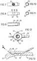
- FIG. 6is a cross-sectional detail view of the directional sleeve electrode 20.
- FIGS. 7, 8, 9, 10 and 11show further details of sleeve electrode 20 and particularly formed tube 52 used in lead 1 according to the present invention.
- sleeve electrode 20is constructed from a formed tube 52 having a central cavity 53.
- sleeve electrode 20has a distal end having a slight taper 38.
- taper 38along with the thin cylindrical shape of formed tube 52 permits sleeve electrode 20 to be readily inserted into the heart with a minimum of irritation and damage to the tissue.
- the precise angle of taper 38may vary and still be within the scope of the present invention.
- a small amount of a medical adhesive 39 or any other biocompatible materialmay be provided at distal end of sleeve electrode 20 in order to further increase the streamline shape of sleeve electrode 20.
- a medical adhesive 39 or any other biocompatible materialmay be provided at distal end of sleeve electrode 20 in order to further increase the streamline shape of sleeve electrode 20.
- sleeve electrode 20further has located within central cavity 53, in the preferred embodiment, a monolithic controlled release device (MCRD) 54.
- MCRD 54is preferably constructed from silicone rubber and a glucocortico steroid.
- Formed tube 52is constructed from a biocompatible conductive material, in the preferred embodiment a platinum-iridium alloy. Distal end of formed tube 52 is crimped about proximal end 60 of suture 21. As seen, proximal end 60 of suture 21 is deformed to increase its diameter and thereby permitting crimping to accomplish a joint.
- Proximal end 56 of formed tube 52is attached to distal end 61 of secondary-conductor 50, preferably by a series of welds 62.
- Substantially all of formed tube 52is covered by an insulative material 63, such as by medical adhesive or polyurethane or any other suitable biocompatible insulative material, except for area 64 proximate holes 65. Area 64 is covered by porous electrode material 70, as best seen in FIG. 7. Holes 65 in formed tube 52 allow MCRD 54 to communicate to tissue proximate sleeve electrode 20. Communication between central cavity 53 and the tissue proximate sleeve electrode 20 is important because it permits use of a steroid or other drug with the electrode. Specifically sleeve electrode 20 may be configured to allow the drug to be eluted through or around the electrode material 70 in order to reduce the acute and chronic inflammation occasioned by the foreign body response to the lead and in particular in the region proximate electrode material 70.
- the anti-inflammatory agentpreferably a derivative of dexamethasone, such as the steroid dexamethasone sodium phosphate, is loaded in MCRD 54.
- the steroidalso is deposited within the pores of porous electrode material 70 by application of a solution of dexamethasone sodium phosphate dissolved in a mixture of isopropanol and distilled or deionized water.
- the small geometric electrode size of sleeve electrode 20is intended to produce very high pacing impedance.
- the porous surface of electrode material 70 together with platinum black electroplatingcontribute to a microscopically large surface area for low polarization and relatively low source impedance.
- the porosity of electrode material 70also facilitates the elution of steroid, adhesion of the platinum black to the electrode surface as well as the chronic fixation of the electrode 20 to the myocardial tissue.
- Electrode material 70is preferably a porous platinum composition coated with platinum black.
- the porosity, together with the platinum black coatingis intended to reduce source impedance and polarization.
- platinumis the preferred material for electrode material 70, it may additionally include or be made entirely from various other materials, including but not limited to such materials as palladium, titanium, tantalum, rhodium, iridium, carbon, vitreous carbon and alloys, oxides and nitrides of such metals or other conductive materials. Of course, some materials are incompatible with others and may not be effectively used together. The limitations of specific materials for use with others is well known in the art. Examples of acceptable electrode materials and associated fabrication techniques employed to achieve the micro-porous structure may be found in Stokes, U.S. Patent No.
- sleeve electrode 20features an electrode surface in only one direction, i.e. only in the direction of area 64.
- a directional electrodehas been found beneficial because it limits the electrical field to be propagated in a direction relative to the lead axis, e.g. perpendicular thereto, from the electrode to the specific tissue of interest, e.g. the myocardium, while concurrently minimizing the exposure of other tissues, e.g. diaphragm or nerves, to the same electrical field.
- the active area of the sleeve electrode 20may be decreased to thereby achieve a higher pacing impedance.
- this designfurther permits the sleeve electrode 20 to be positioned at a point where the electrode is proximal to desired sections of the myocardium as well as permitting placement within the epicardium at the optimal sensing vector.
- sleeve electrode 20electrically communicates with the myocardial tissue in a direction perpendicular to the longitudinal axis of the lead, as best seen in FIG. 4. Other directions may, however, be used, such as an electrode which would electrically communicate with the myocardial tissue in a direction parallel to the longitudinal axis of the lead. In fact any specific direction may be used.
- Pad electrode 15has a surface area approximately ten times (10X) greater than sleeve electrode 20.
- pad electrode 15has a surface area of 12 square mm and sleeve electrode 20 has a surface area of 0.8 square mm
- Implantation of lead 1is begun by inserting a traumatic needle 22 through myocardial tissue 23 to its exit at location 80. As seen in FIG. 13, suture 21 is pulled until sleeve electrode 20 is properly positioned within part of channel 81, in electrical contact with tissue of heart 13. Suture 21 is preferably PROLENE®. Tension is exerted on coiled section 71 by pulling suture 21 in direction of arrow 82, and the resistive friction between sleeve electrode 20 and heart 13 causes coiled section 71 to stretch and become temporarily elongated.
- suture 21While tension is continuously applied to suture 21 for maintaining coiled section 71 in its extended and elongated state, suture 21 is severed with a conventional cutting instrument, such as a pair of scissors to remove the excess portion and dispose of needle 22.
- a conventional cutting instrumentsuch as a pair of scissors to remove the excess portion and dispose of needle 22.
- the number of turnsmay be selected by the surgeon, depending on whether lead 1 is inserted in the atrial or ventricular wall, and depending on the age or physical condition of the patient. If lead 1 is used for ventricular applications, for example, it may be acceptable to leave most, if not all of turns 72, 73 and 74 within channel 81 of the myocardium tissue 23. If lead 1 is used for pediatric or atrial applications, however, then a lesser number of turns 72 and 73 of coiled section 71 might be used to retain lead 1 in place.
- the lead 1 of the present inventionmay feature coding along suture 21 as disclosed in U.S. Patent No. 5,217,027 to Hermens.
- Special coding along suture 21may be accomplished through a series of color codings or identification marks along suture 21 to indicate to the surgeon the length to which the suture 21 must be pulled through myocardium tissue 23 in order to retain the lead in position.
- markings 86, 87 and 88such as a color coded indentation, visually indicate to the surgeon the number of turns 72, 73 and 74 within channel 81.
- suture 21is cut to the desired length and coiled section 71 retracts towards sleeve electrode 20 within channel 81.
- Coiled section 71due to the compressive elasticity of turns 72, 73 and 74, wedges in the myocardial tissue 23 and thereby firmly affixes sleeve electrode 20 in tissue 23. If lead 1 is unsatisfactorily positioned, however, it may be removed by gently retracting it from channel 81 through traction along lead body 14. Lead 1 may then be reinserted at the next desired site as described above, assuming, of course that suture 21 and in particular needle 20 has not been separated.
- pad electrode 15is placed flush against the surface of myocardial tissue 23. If desired pad electrode 15 may be sutured in place through the use of suture holes and suture 89, although suturing is not always necessary.
- FIG. 16depicts a plan view of the distal end of an alternative embodiment of a lead according to the present invention. As seen this embodiment is similar to that previously described with the exception of having a pair of secondary-conductors 50a and 50b, each having an electrode. As seen, the sleeve electrode 20 on secondary-conductor 50a is similar to that previously described. Electrode 120 on secondary-conductor 50b is constructed in a similar manner as sleeve electrode 20 with the exception of not being directional nor utilizing an MCRD 54. In addition electrode 120 has a surface area approximately ten times (10X) greater than sleeve electrode 20, in the preferred embodiment electrode 120 has a surface area of 12 square mm and sleeve electrode 20 has a surface area of 0.8 square mm
- each suturehas a needle 20 attached to it.
- the second electrode 120has a further suture 21 connected thereto and it has a tapered distal end similar to electrode 20, for easy insertion.
- the present inventionmay further be incorporated within a unipolar lead.
- a unipolar embodimentwould differ from the bipolar embodiment through the absence of either pad electrode 15 or sleeve electrode 20.
Landscapes
- Health & Medical Sciences (AREA)
- Heart & Thoracic Surgery (AREA)
- Cardiology (AREA)
- Engineering & Computer Science (AREA)
- Biomedical Technology (AREA)
- Nuclear Medicine, Radiotherapy & Molecular Imaging (AREA)
- Radiology & Medical Imaging (AREA)
- Life Sciences & Earth Sciences (AREA)
- Animal Behavior & Ethology (AREA)
- General Health & Medical Sciences (AREA)
- Public Health (AREA)
- Veterinary Medicine (AREA)
- Electrotherapy Devices (AREA)
Description
- This invention relates to an electrical lead used toprovide electrical signals to a tissue, and especially ahuman organ, such as a heart, and is particularlyapplicable, to a chronically implanted steroid elutingcardiac lead.
- Electrical stimulation of body tissue and organs isoften used as a method of treating various pathologicalconditions. Such stimulation generally entails makingan electrical contact between body tissue and anelectrical pulse generator through use of one or morestimulation leads. Various lead structures and varioustechniques for implanting these lead structures intobody tissue and particularly the heart have beendeveloped.
- For example, a transvenous endocardial leadestablishes electrical contact between an electricalpulse generator and heart through placement of a lead inthe venous system. Specifically, an electrical lead ispassed through a vein, with the assistance of afluoroscope, into the heart where it is held in contactwith the endocardium by the trabeculae of the heartchamber, such as the ventricle.
- There are, however, disadvantages to this type oflead, including: possible damage to the vein, such asperforation or laceration during insertion; possiblefailure to securely attach and maintain electricalcontact with the heart; possible perforation of theheart wall by the lead; and because direct visualinspection of the lead placement is not possible,possible improper lead placement in the heart.
- Besides these possible problems, there areadditional situations in which the installation of atransvenous endocardial pacing lead is either notfeasible or not recommended. These situations includethe case when the vein which would be used is damaged or too small, or the situation in which a physical oranatomical anomaly prevents the placement of atransvenous endocardial lead within the heart, such asthe presence of an artificial heart valve.
- In particular a transvenous endocardial lead isoften either not feasible or not recommended inchildren. One problem presented by use of a transvenousendocardial lead stems from the growth a childundergoes. Specifically, upon chronic implantation of atransvenous lead the lead body is subject to fibroticencapsulation within the venous system. Thisencapsulation fixes the lead body in place, especiallyrelative to the walls of the venous system. Over time,as the child grows the venous system elongates. Becausethe lead is fixed by fibrotic growth, as the venoussystem elongates the lead electrode will be pulled ordislodged from effective contact with the endocardium.In addition, because the venous system of a child issmaller than an adult, it is less tolerant of thepartial occluding of a vein by a transvenous lead. Inthese cases use of a myocardial lead applied from theepicardium is often indicated or preferred.
- EP-A-083674 discloses a temporary lead with aninsertion tool. The lead has an electrical connector ata proximal end and an electrode at a distal end. Alength of surgical thread is permanently attached to theelectrode, a helix is moulded into the thread and acurved needle is attached to the thread.
- A myocardial lead offers a significant advantage toa transvenous endocardial lead with regard to children.Because a myocardial lead is attached to the heart notthrough the venous system but rather through a thoracicaccess, a sufficient amount of spare lead length toaccommodate growth may be located or looped within thethoracic cavity. In addition a myocardial lead does noteven partially occlude a part of the relatively smallvenous system of a child.
- A number of different myocardial leads have beendeveloped, as have various techniques for implantingthem within the myocardial tissue of the heart.Typically, myocardial leads are attached from theexterior of the heart through a thoracic access.
- One form of such lead is a screw-in lead. This leadconsists of a rigid helical coil which is used to fixthe electrode to the myocardial tissue. Examples ofsuch a lead may be found in U.S. Patent No. 5,154,183to Kreyenhagen et al., U.S. Patent No. 5,143,090 tobutcher et al., U.S. Patent No. 5,085,218 to Heil Jr. etal., and U.S. Patent No. 4,010,758 to Rockland et al.One problem which has been found to exist with suchleads, however, is the inflammatory tissue reaction (orforeign body response) of the tissue to the device andespecially the rigid helix. Inflammatory tissue reactionis caused, in part, from the presence of a foreignobject within the tissue. It has been found that thepresence of a rigid structure within the myocardiumchronically causes at least some of the immediatelysurrounding myocardial tissue to be replaced with eitherfat or collagen or both. Such tissue reactiondetrimentally affects the electrical properties of thesurrounding tissue, and thus the lead performance.
- One means of treating the inflammatory response hasbeen to provide a means for delivering a drug near theelectrode to mitigate the inflammatory tissue reactiondescribed above. Specifically it has been found thateluting an anti-inflammatory agent, such as aglucocortico steroid, minimizes tissue irritation, helpsreduce or eliminate threshold peaking and furtherassists in maintaining low acute and chronic pacingthresholds.
- In addition a tissue reaction due to the mechanicalmotion of the cardiac tissue relative to the helicalcoil has been found to arise in the surrounding tissue.Because the heart is a constantly moving organ, the presence of a stationary and stiff fixation coilexacerbates the normal build-up of collagen and fat nearthe helical coil. Such tissues may detrimentally affectthe electrical performance of the surrounding tissue.As a result stimulation thresholds may rise. As such, achronic lead which mitigates such tissue reactions wouldbe of benefit.
- Maintenance of stimulation thresholds is animportant criterion for a chronically implanted cardiaclead. Implantable pulse generators are powered by abattery having a limited life. After an extended periodof time, such as five years, the battery will bedepleted and the implanted pulse generator must besurgically replaced. Therefore, it is an objective tominimize the electrical current drain on the powersource by appropriate design of the pacemaker'selectrodes and to provide for reduced stimulationvoltage.
- It is an object of the invention to provide abipolar myocardial lead which permits bipolar pacing orsensing with the installation of only a single lead to apatient's heart or to another organ of the patient,which lead is simple to implant and provides a highlysecure fixation.
- It is another object of this invention to provide amyocardial lead which provides highly secure fixationwhile minimizing tissue inflammation.
- It is another object of this invention to provide amyocardial lead which minimizes the electrical currentdrain on the power source by appropriate design of theelectrode and to provide for reduced stimulationvoltage.
- It is another object of this invention to provide amyocardial lead which permits the elution of an anti-inflammatoryagent at the electrode-tissue interface toassist in maintaining low acute and chronic pacingthresholds.
- In accordance with the above objects there isprovided a lead for establishing electrical contactbetween body tissue and a medical device, the leadhaving a longitudinal axis, the lead comprising:
- a length of flexible conductor having a distal endand a longitudinal axis, the conductor having aninsulative casing;
- a member electrically connected to the conductor;
- a length of suture having a coiled portion coupledto the member; and
- a needle attached to an end of the suture,;
characterized by the member having an insulativecovering, the member electrically communicating with anexterior of the insulative covering only in a firstdirection relative to the longitudinal axis of the leadthrough a porous conductive material; and furthercharacterized by the member having a chamber, thechamber communicating with the exterior of theinsulative covering through a port, and the memberhaving means positioned in the chamber for dispensing adrug through the port. - The preferred embodiment provides a bipolarmyocardial lead having two electrodes. The firstelectrode is designed to be implanted within themyocardium while the second electrode is designed to bepositioned on the epicardial surface of the heart.Fixation of the lead is accomplished through a length ofcoiled suture attached at one end of the lead. Theelectrodes are configured for directional electricalstimulation. The lead includes a drug for deliverythrough an electrode to the myocardium. Such a leadoffers relatively low pacing thresholds, efficient highpacing impedance, and excellent sensing in aconfiguration which is relatively easy to implant.
- These and other objects and advantages of thepresent invention may be fully understood andappreciated in conjunction with the attached drawings and the following detailed description of the preferredembodiments given by way of example only and where thesame numerals are employed to denote the same or similarfeatures throughout. The drawings are not necessarilyto scale.
- FIG. 1 is a schematic view of a lead in use with animplantable pulse generator system.
- FIG. 2 shows a lead according to the presentinvention attached to a heart and an implantable pulsegenerator system.
- FIG. 3 is a cross-sectional view of the lead body ofa lead according to the present invention.
- FIG. 4 is a plan view of the distal end of a leadaccording to the present invention.
- FIG. 5 is a cross-sectional view of the padelectrode used in a lead according to the presentinvention.
- FIG. 6 is a cross-sectional view of the sleeveelectrode used in a lead according to the presentinvention.
- FIG. 7 is a plan view of a sleeve electrode used ina lead according to the present invention.
- FIG. 8 is a plan view of a formed tube used in thesleeve electrode of the present invention.
- FIG. 9, 10 and 11 are cross-sectional views of theformed tube used in the sleeve electrode of the presentinvention.
- FIG. 12 is a plan view of a pad electrode used in alead according to the present invention.
- FIG. 13 shows the lead as it is being positionedwithin the myocardium.
- FIG. 14 shows the lead chronically implanted afterthe suture has been cut and the pad electrode sutured inplace.
- FIG. 15 shows a detail of the coiled section ofsuture having identification markings.
- FIG. 16 depicts a plan view of the distal end of an alternative embodiment of a lead according. to thepresent invention.
- FIG. 1 is a schematic view of a lead in use with apacing system 2, showing conductors 3, 4 electricallyconnected to an
implantable pulse generator 5.Implantable pulse generator 5 is constructed from abattery 9, asense amplifier 10, a microprocessor 11,and anoutput amplifier 12. Through such a pacingsystem 2 the lead of the present invention may be usedto electrically stimulate and sense body tissue, such asa heart. - FIG. 2 shows a
lead 1 according to the presentinvention in use as part of a pacing system 2 andimplanted within aheart 13.Lead 1, as seen, hasessentially seven parts or sections: connector 8,leadbody 14,pad electrode 15, secondary-lead body 16,sleeve electrode 20,suture 21 and needle 22 (not shownin FIG. 2 but shown in FIG. 4.) As seen,pad electrode 15 is positioned on the surface ofheart 13 andsleeveelectrode 20 is implanted within the cardiac tissue, andspecifically withinmyocardium 23. - As seen in FIG. 2 connector pin 8 electricallyconnects
implantable pulse generator 5 to lead 1, andspecifically to leadbody 14. A cross-section ofleadbody 14 may be seen in FIG. 3. As seen,lead body 14is constructed from amulti-lumen insulative cover 24andconductors 25.Insulative cover 24 is constructedfrom a composite of materials, in the preferredembodiment outer tube 34 is polyurethane andinner tube 35 is polyvinylidene fluoride.Inner tube 35 provideslongitudinal stiffness to leadbody 14 to prevent itfrom stretching during implantation and possiblerepositioning, as described below. Althoughpolyvinylidene fluoride is the preferred material forinner tube 35, other materials which provide a lead bodyhaving sufficient longitudinal stiffness may also beused.Insulative cover 24 has fourlumens central conductors 25 areelectrically connected to padelectrode 15, while theother conductors are electrically connected to thesleeve electrode 20. In thepreferred embodimentconductors 25 are a bundled stranded wire. A suitablebundled stranded wire may be formed from a bundle ofnine wires, each made from a MP35N alloy and having adiameter of 0.025mm (0.001 inches), the bundle is thendrawn through a die to yield a bundle diameter of0.125mm (0.005 inches). Although in thepreferredembodiment conductors 25 are bundled stranded wire,other conductor embodiments may be used, such as, forexample, multifilar wire and coiled conductors. Furtherdetails concerning the design and construction of amulti-lumen lead body and BSW conductors may be found inU.S. patents 5,324,321 and 5,303,704. - FIG. 4 is a plan view of distal end 40 of
lead body 14showing pad electrode 15 connected thereto.Padelectrode 15 is constructed frompad housing 41 andpan 42, as best seen in FIG. 5.Pad housing 41 has a pairoffixation wings 46, as seen in FIGS. 4 and 12.Holes 47 infixation wings 46permit pad electrode 15 to befixed by sutures to heart. Other methods offixing padelectrode 15 to heart may be used besides sutures,including, for example, fibrin glue, cyanoacrylateadhesive, staples, or the provision of a polyethyleneterephthalate mesh on the lower surface ofpad housing 41. As seen in FIG. 5, region 49 withinpad housing 41is back filled with silicone medical adhesive duringassembly to fixpan 42 in place.Pan 42 features acrimp-cover 43 to crimp aboutconductors 25 and therebyelectrically connectconductors 25 oflead body 14.Pan 42 is covered byelectrode material 70.Distal end 44ofpad housing 41 features a skirt-portion 45 into whichsecondary-lead body 16 is attached. - Secondary-
lead body 16, as best seen in FIGS. 5 and6 consists of a secondary-conductor 50 surrounded by asecondary-insulative cover 51. Secondary-insulativecover 51 is made from a biocompatible insulativematerial, preferably polyurethane although siliconerubber may also be used. Secondary-conductor 50 is acoiled conductor. A coiled conductor is preferredbecause this portion of thelead 1 rides directly upon,and within,heart 13 and thus is subject to compressiveloading during cardiac contraction. Of course it shouldbe understood that other conductors besides a coiledconductor may be provided for secondary-conductor 50without departing from the scope of the presentinvention. Secondary-conductor 50 is connected toconductors 25 byjunction 48. Specificallyjunction 48is crimped aboutconductors 25.Junction 48 is furtherwelded to secondary-conductor 50. Secondary-conductor 50 is preferably constructed from a MP35N alloy althougha platinum iridium alloy may also be used. - FIG. 6 is a cross-sectional detail view of the
directional sleeve electrode 20. FIGS. 7, 8, 9, 10 and11 show further details ofsleeve electrode 20 andparticularly formedtube 52 used inlead 1 according tothe present invention. As seensleeve electrode 20 isconstructed from a formedtube 52 having acentralcavity 53. As seen in FIG. 6,sleeve electrode 20 has adistal end having aslight taper 38. The use oftaper 38 along with the thin cylindrical shape of formedtube 52permits sleeve electrode 20 to be readily insertedinto the heart with a minimum of irritation and damageto the tissue. The precise angle oftaper 38 may varyand still be within the scope of the present invention.In addition a small amount of amedical adhesive 39 orany other biocompatible material may be provided atdistal end ofsleeve electrode 20 in order to furtherincrease the streamline shape ofsleeve electrode 20.As discussed above minimizing the trauma of lead insertion, as well as minimizing the trauma caused bythe chronic implantation of a rigid electrode, isimportant to thereby minimize tissue reaction and thusthresholds. - As previously mentioned,
sleeve electrode 20 furtherhas located withincentral cavity 53, in the preferredembodiment, a monolithic controlled release device(MCRD) 54.MCRD 54 is preferably constructed fromsilicone rubber and a glucocortico steroid.Formed tube 52 is constructed from a biocompatible conductivematerial, in the preferred embodiment a platinum-iridiumalloy. Distal end of formedtube 52 is crimped aboutproximal end 60 ofsuture 21. As seen,proximal end 60ofsuture 21 is deformed to increase its diameter andthereby permitting crimping to accomplish a joint.Proximal end 56 of formedtube 52 is attached todistalend 61 of secondary-conductor 50, preferably by a seriesofwelds 62. Substantially all of formedtube 52 iscovered by aninsulative material 63, such as by medicaladhesive or polyurethane or any other suitablebiocompatible insulative material, except forarea 64proximate holes 65.Area 64 is covered byporouselectrode material 70, as best seen in FIG. 7.Holes 65in formedtube 52 allowMCRD 54 to communicate to tissueproximate sleeve electrode 20. Communication betweencentral cavity 53 and the tissueproximate sleeveelectrode 20 is important because it permits use of asteroid or other drug with the electrode. Specificallysleeve electrode 20 may be configured to allow the drugto be eluted through or around theelectrode material 70in order to reduce the acute and chronic inflammationoccasioned by the foreign body response to the lead andin particular in the regionproximate electrode material 70. - The anti-inflammatory agent, preferably a derivativeof dexamethasone, such as the steroid dexamethasonesodium phosphate, is loaded in
MCRD 54. The steroid also is deposited within the pores ofporous electrodematerial 70 by application of a solution ofdexamethasone sodium phosphate dissolved in a mixture ofisopropanol and distilled or deionized water. The smallgeometric electrode size ofsleeve electrode 20 isintended to produce very high pacing impedance. Theporous surface ofelectrode material 70 together withplatinum black electroplating contribute to amicroscopically large surface area for low polarizationand relatively low source impedance. The porosity ofelectrode material 70 also facilitates the elution ofsteroid, adhesion of the platinum black to the electrodesurface as well as the chronic fixation of theelectrode 20 to the myocardial tissue. Electrode material 70 is preferably a porousplatinum composition coated with platinum black. Theporosity, together with the platinum black coating isintended to reduce source impedance and polarization.Although platinum is the preferred material forelectrode material 70, it may additionally include or bemade entirely from various other materials, includingbut not limited to such materials as palladium,titanium, tantalum, rhodium, iridium, carbon, vitreouscarbon and alloys, oxides and nitrides of such metals orother conductive materials. Of course, some materialsare incompatible with others and may not be effectivelyused together. The limitations of specific materialsfor use with others is well known in the art. Examplesof acceptable electrode materials and associatedfabrication techniques employed to achieve the micro-porousstructure may be found in Stokes, U.S. Patent No.4,506,680 and related Medtronic U.S. Patent Nos.4,577,642; 4,606,118 and 4,711,251 and in the Richter etal., U.S. Patent No. 4,773,433; Heil Jr. et al., U.S.Patent No. 4,819,661; Thoren et al., U.S. Patent No.4,149,542; Robblee, U.S. Patent No. 4,677,989; Heil Jr.et al., U.S. Patent No. 4,819,662; Mund et al., U.S. Patent No. 4,603,704; Skalsky et al., U.S. Patent No.4,784,161; Szilagyi, U.S. Patent No. 4,784,160.- As seen,
sleeve electrode 20 features an electrodesurface in only one direction, i.e. only in thedirection ofarea 64. A directional electrode has beenfound beneficial because it limits the electrical fieldto be propagated in a direction relative to the leadaxis, e.g. perpendicular thereto, from the electrode tothe specific tissue of interest, e.g. the myocardium,while concurrently minimizing the exposure of othertissues, e.g. diaphragm or nerves, to the sameelectrical field. In addition, because the electricalfield is more precisely emitted, the active area of thesleeve electrode 20 may be decreased to thereby achievea higher pacing impedance. In addition, this designfurther permits thesleeve electrode 20 to be positionedat a point where the electrode is proximal to desiredsections of the myocardium as well as permittingplacement within the epicardium at the optimal sensingvector. Design ofsleeve electrode 20, moreover,besides permitting directional stimulation and sensingalso permits the incorporation of an MCRD as well aspresenting an easy to insert profile. In the preferredembodiment sleeve electrode 20 electrically communicateswith the myocardial tissue in a direction perpendicularto the longitudinal axis of the lead, as best seen inFIG. 4. Other directions may, however, be used, such asan electrode which would electrically communicate withthe myocardial tissue in a direction parallel to thelongitudinal axis of the lead. In fact any specificdirection may be used. Pad electrode 15 has a surface area approximatelyten times (10X) greater thansleeve electrode 20. Inthe preferredembodiment pad electrode 15 has a surfacearea of 12 square mm andsleeve electrode 20 has asurface area of 0.8 square mm- Implantation of
lead 1 is begun by inserting atraumatic needle 22 throughmyocardial tissue 23 to itsexit atlocation 80. As seen in FIG. 13,suture 21 ispulled untilsleeve electrode 20 is properly positionedwithin part ofchannel 81, in electrical contact withtissue ofheart 13.Suture 21 is preferably PROLENE®.Tension is exerted on coiledsection 71 by pullingsuture 21 in direction ofarrow 82, and the resistivefriction betweensleeve electrode 20 andheart 13 causescoiledsection 71 to stretch and become temporarilyelongated. - While tension is continuously applied to suture 21for maintaining coiled
section 71 in its extended andelongated state,suture 21 is severed with aconventional cutting instrument, such as a pair ofscissors to remove the excess portion and dispose ofneedle 22. - In some applications it may be desirable to sever
suture 21 at a point which includes at least a part ofthecoils 71. This will ensure only a selected numberofturns channel 81. The number of turns may be selectedby the surgeon, depending on whetherlead 1 is insertedin the atrial or ventricular wall, and depending on theage or physical condition of the patient. Iflead 1 isused for ventricular applications, for example, it maybe acceptable to leave most, if not all ofturns channel 81 of themyocardium tissue 23.Iflead 1 is used for pediatric or atrial applications,however, then a lesser number ofturns section 71 might be used to retainlead 1 inplace. In order to facilitate the selection process thelead 1 of the present invention may feature coding alongsuture 21 as disclosed in U.S. Patent No. 5,217,027 toHermens. Special coding alongsuture 21 may beaccomplished through a series of color codings oridentification marks alongsuture 21 to indicate to thesurgeon the length to which thesuture 21 must be pulled throughmyocardium tissue 23 in order to retain the leadin position. In the present illustration shown in FIG.15,markings turns channel 81. - Once the electrode is satisfactorily positioned
suture 21 is cut to the desired length and coiledsection 71 retracts towardssleeve electrode 20 withinchannel 81.Coiled section 71, due to the compressiveelasticity ofturns myocardial tissue 23 and thereby firmly affixessleeveelectrode 20 intissue 23. Iflead 1 isunsatisfactorily positioned, however, it may be removedby gently retracting it fromchannel 81 through tractionalonglead body 14.Lead 1 may then be reinserted atthe next desired site as described above, assuming, ofcourse that suture 21 and inparticular needle 20 hasnot been separated. - Once
sleeve electrode 20 is positioned,padelectrode 15 is placed flush against the surface ofmyocardial tissue 23. If desiredpad electrode 15 maybe sutured in place through the use of suture holes andsuture 89, although suturing is not always necessary. - FIG. 16 depicts a plan view of the distal end of analternative embodiment of a lead according to thepresent invention. As seen this embodiment is similarto that previously described with the exception ofhaving a pair of secondary-
conductors sleeve electrode 20 onsecondary-conductor 50a is similar to that previouslydescribed.Electrode 120 on secondary-conductor 50b isconstructed in a similar manner assleeve electrode 20with the exception of not being directional norutilizing anMCRD 54. Inaddition electrode 120 has asurface area approximately ten times (10X) greater thansleeve electrode 20, in thepreferred embodimentelectrode 120 has a surface area of 12 square mm andsleeve electrode 20 has a surface area of 0.8 square mm - Installation of this embodiment is the same asdescribed above, but requiring a pair of
sutures 21 tobe inserted. Although not shown, each suture has aneedle 20 attached to it. In particular, thesecondelectrode 120 has afurther suture 21 connected theretoand it has a tapered distal end similar toelectrode 20,for easy insertion. - The present invention may further be incorporatedwithin a unipolar lead. Such a unipolar embodimentwould differ from the bipolar embodiment through theabsence of either
pad electrode 15 orsleeve electrode 20. - While the embodiment of the present invention hasbeen described in particular applications, it will beunderstood the invention may be practised in other leadand electrode technologies where the aforementionedcharacteristics are desirable, including neurologicaland muscle stimulation applications.
- Furthermore, although the invention has beendescribed in detail with particular reference to apreferred embodiment and alternative embodimentsthereof, it will be understood that variations andmodifications can be effected within the scope of thefollowing claims. Such modifications may includesubstituting elements or components which performsubstantially the same function in substantially thesame way to achieve substantially the same result forthose described herein.
Claims (10)
- A lead (1) for establishing electrical contactbetween body tissue (13) and a medical device (5), thelead having a longitudinal axis, the lead comprising:a length of flexible conductor (14) having a distalend and a longitudinal axis, the conductor (14) having aninsulative casing (34);a member (52) electrically connected to theconductor (14);a length of suture (21) having a coiled portion (71)coupled to the member (52); anda needle (22) attached to an end of the suture (21);
characterized by the member (52) having an insulativecovering (63), the member (52) electrically communicatingwith an exterior of the insulative covering (63) only in afirst direction relative to the longitudinal axis of thelead (1) through a porous conductive material (70); andfurther characterized by the member (52) having a chamber(53), the chamber (53) communicating with the exterior of theinsulative covering (63) through a port (65), and the member(52) having means (54) positioned in the chamber fordispensing a drug through the port (65). - A lead according to claim 1 in which the member (52)is cylindrical and coaxial with the longitudinal axis ofthe flexible conductor (14).
- A lead according to claim 1 or 2 in which theporous conductive material (70) has a first surface area, andsaid lead further comprising a second member (42,120)electrically connected to a conductor, the second member (42,120)having an insulated area and an exposed area, theexposed area having a second surface area of at leastten times greater than the first surface area.
- A lead according to claim 3 wherein the first surface area is substantially 0.8 square mm and thesecond surface area of the second member (42,120) issubstantially 12 square mm.
- A lead according to claim 4 wherein theconductor (14) splits into two secondary conductors(50a,50b), the first (20) and second (120) members beingconnected to the respective secondary conductors, and alength of suture (21) is attached to an end of the secondmember (120).
- A lead according to claim 5 wherein the secondmember (120) has a tapered distal end.
- A lead according to any preceding claim whereinthe first direction is perpendicular to the longitudinalaxis of the lead.
- A lead according to any of claims 1 to 5wherein the first direction is parallel to thelongitudinal axis of the lead.
- A lead according to claim 3 wherein the exposedarea is planar.
- A lead according to any preceding claim whereinthe porous conductive material (70) is formed of porousmetallic or other conductive materials from the class ofmaterials consisting essentially of platinum, palladium,titanium, tantalum, rhodium, iridium, carbon, vitreouscarbon and alloys, oxides and nitrides of such metals orother conductive materials.
Applications Claiming Priority (2)
| Application Number | Priority Date | Filing Date | Title |
|---|---|---|---|
| US08/189,825US5489294A (en) | 1994-02-01 | 1994-02-01 | Steroid eluting stitch-in chronic cardiac lead |
| US189825 | 1994-02-01 |
Publications (2)
| Publication Number | Publication Date |
|---|---|
| EP0668087A1 EP0668087A1 (en) | 1995-08-23 |
| EP0668087B1true EP0668087B1 (en) | 1999-12-29 |
Family
ID=22698926
Family Applications (1)
| Application Number | Title | Priority Date | Filing Date |
|---|---|---|---|
| EP95300627AExpired - LifetimeEP0668087B1 (en) | 1994-02-01 | 1995-02-01 | Drug eluting stitch-in chronic lead |
Country Status (6)
| Country | Link |
|---|---|
| US (1) | US5489294A (en) |
| EP (1) | EP0668087B1 (en) |
| JP (1) | JP2929073B2 (en) |
| AU (1) | AU672543B2 (en) |
| CA (1) | CA2141530C (en) |
| DE (1) | DE69514126T2 (en) |
Cited By (1)
| Publication number | Priority date | Publication date | Assignee | Title |
|---|---|---|---|---|
| US11844949B2 (en) | 2014-09-04 | 2023-12-19 | AtaCor Medical, Inc. | Cardiac defibrillation |
Families Citing this family (161)
| Publication number | Priority date | Publication date | Assignee | Title |
|---|---|---|---|---|
| US5716392A (en)* | 1996-01-05 | 1998-02-10 | Medtronic, Inc. | Minimally invasive medical electrical lead |
| DE19611777C2 (en)* | 1996-03-14 | 2001-09-27 | Biotronik Mess & Therapieg | Arrangement for electrical contacting |
| US6006134A (en)* | 1998-04-30 | 1999-12-21 | Medtronic, Inc. | Method and device for electronically controlling the beating of a heart using venous electrical stimulation of nerve fibers |
| IT1292016B1 (en)* | 1997-05-28 | 1999-01-25 | Valerio Cigaina | IMPLANT DEVICE PARTICULARLY FOR ELECTROSTIMULATION AND / OR ELECTRO-REGISTRATION OF ENDOABDOMINAL VISCERS |
| US6477423B1 (en) | 1997-05-28 | 2002-11-05 | Transneuronix, Inc. | Medical device for use in laparoscopic surgery |
| US6321124B1 (en) | 1997-05-28 | 2001-11-20 | Transneuronix, Inc. | Implant device for electrostimulation and/or monitoring of endo-abdominal cavity tissue |
| US6381495B1 (en) | 1997-05-28 | 2002-04-30 | Transneuronix, Inc. | Medical device for use in laparoscopic surgery |
| US5991668A (en)* | 1997-09-25 | 1999-11-23 | Medtronic, Inc. | Medical electrical lead |
| US6110500A (en)* | 1998-03-25 | 2000-08-29 | Temple University | Coated tablet with long term parabolic and zero-order release kinetics |
| IT1301986B1 (en)* | 1998-07-31 | 2000-07-20 | Valerio Cigaina | LAPAROSCOPIC FORCEPS FOR SUTURE. |
| US6061595A (en)* | 1999-01-04 | 2000-05-09 | Pacesetter, Inc. | Laser spot weld winding to connector joint |
| US6293594B1 (en) | 1999-01-20 | 2001-09-25 | Pacesetter, Inc. | Joining a winding to a connector using a transition ring |
| IT1313608B1 (en) | 1999-08-06 | 2002-09-09 | Valerio Cigaina | EQUIPMENT FOR STIMULATION OF A COMPLETE STATE OF CONTINENCE OF THE NEOSFINTER IN THE PACK OF CONTINENT NEOSTOMIES AND |
| US6510332B1 (en) | 1999-08-30 | 2003-01-21 | Transneuronix, Inc. | Electrode leads for use in laparoscopic surgery |
| US6463335B1 (en) | 1999-10-04 | 2002-10-08 | Medtronic, Inc. | Temporary medical electrical lead having electrode mounting pad with biodegradable adhesive |
| US20070043435A1 (en)* | 1999-11-17 | 2007-02-22 | Jacques Seguin | Non-cylindrical prosthetic valve system for transluminal delivery |
| US8579966B2 (en) | 1999-11-17 | 2013-11-12 | Medtronic Corevalve Llc | Prosthetic valve for transluminal delivery |
| US7018406B2 (en)* | 1999-11-17 | 2006-03-28 | Corevalve Sa | Prosthetic valve for transluminal delivery |
| US8016877B2 (en)* | 1999-11-17 | 2011-09-13 | Medtronic Corevalve Llc | Prosthetic valve for transluminal delivery |
| US8241274B2 (en) | 2000-01-19 | 2012-08-14 | Medtronic, Inc. | Method for guiding a medical device |
| US7749245B2 (en) | 2000-01-27 | 2010-07-06 | Medtronic, Inc. | Cardiac valve procedure methods and devices |
| US7096070B1 (en) | 2000-02-09 | 2006-08-22 | Transneuronix, Inc. | Medical implant device for electrostimulation using discrete micro-electrodes |
| EP1401358B1 (en)* | 2000-06-30 | 2016-08-17 | Medtronic, Inc. | Apparatus for performing a procedure on a cardiac valve |
| AU2001273088A1 (en)* | 2000-06-30 | 2002-01-30 | Viacor Incorporated | Intravascular filter with debris entrapment mechanism |
| WO2002026317A1 (en)* | 2000-09-26 | 2002-04-04 | Transneuronix, Inc. | Method and apparatus for treating obesity by electrical stimulation of the gastrointestinal tract using sensed activity |
| US6615084B1 (en) | 2000-11-15 | 2003-09-02 | Transneuronix, Inc. | Process for electrostimulation treatment of morbid obesity |
| US20060206160A1 (en)* | 2000-11-15 | 2006-09-14 | Transneuronix, Inc. | Process and electrostimulation device for treating obesity and/or gastroesophageal reflux disease |
| US6876885B2 (en)* | 2001-01-31 | 2005-04-05 | Medtronic, Inc. | Implantable bifurcated gastrointestinal lead with active fixation |
| US6952613B2 (en) | 2001-01-31 | 2005-10-04 | Medtronic, Inc. | Implantable gastrointestinal lead with active fixation |
| US7099718B1 (en) | 2001-05-29 | 2006-08-29 | Advanced Bionics Corporation | Neural stimulation lead fixation |
| US8295945B1 (en) | 2001-05-29 | 2012-10-23 | Boston Scientific Neuromodulation Corporation | Neural stimulation lead fixation |
| US7983766B1 (en)* | 2001-05-29 | 2011-07-19 | Boston Scientific Neuromodulation Corporation | Method of securing a neural stimulation lead |
| US6697675B1 (en) | 2001-06-14 | 2004-02-24 | Pacesetter, Inc. | Laser welded joint for implantable lead |
| US7544206B2 (en) | 2001-06-29 | 2009-06-09 | Medtronic, Inc. | Method and apparatus for resecting and replacing an aortic valve |
| US8623077B2 (en) | 2001-06-29 | 2014-01-07 | Medtronic, Inc. | Apparatus for replacing a cardiac valve |
| US8771302B2 (en)* | 2001-06-29 | 2014-07-08 | Medtronic, Inc. | Method and apparatus for resecting and replacing an aortic valve |
| FR2826863B1 (en) | 2001-07-04 | 2003-09-26 | Jacques Seguin | ASSEMBLY FOR PLACING A PROSTHETIC VALVE IN A BODY CONDUIT |
| FR2828091B1 (en) | 2001-07-31 | 2003-11-21 | Seguin Jacques | ASSEMBLY ALLOWING THE PLACEMENT OF A PROTHETIC VALVE IN A BODY DUCT |
| US7097659B2 (en)* | 2001-09-07 | 2006-08-29 | Medtronic, Inc. | Fixation band for affixing a prosthetic heart valve to tissue |
| EP1453382A4 (en)* | 2001-11-08 | 2005-05-18 | Univ California | METHODS AND COMPOSITIONS FOR CORRECTION OF CARDIAC CONDUCTION DISORDERS |
| US6671562B2 (en) | 2001-11-09 | 2003-12-30 | Oscor Inc. | High impedance drug eluting cardiac lead |
| CN1649641A (en)* | 2002-05-08 | 2005-08-03 | 加利福尼亚大学董事会 | Systems and methods for forming unresectable heart block |
| WO2003094855A1 (en)* | 2002-05-08 | 2003-11-20 | The Regents Of The University Of California | System and method for treating cardiac arrhythmias with fibroblast cells |
| US20040106896A1 (en)* | 2002-11-29 | 2004-06-03 | The Regents Of The University Of California | System and method for forming a non-ablative cardiac conduction block |
| EP1509252A4 (en)* | 2002-05-08 | 2006-08-16 | Univ California | METHOD AND COMPOSITIONS FOR CORRECTING HEART TRANSFER FAULTS |
| US20040133243A1 (en)* | 2002-07-26 | 2004-07-08 | Santamore William P. | Cardiac rhythm management system with intramural myocardial pacing leads and electrodes |
| JP2005533613A (en)* | 2002-07-26 | 2005-11-10 | トランスニューロニックス インコーポレイテッド | Improved method for electrical stimulation treatment of morbid obesity |
| CO5500017A1 (en)* | 2002-09-23 | 2005-03-31 | 3F Therapeutics Inc | MITRAL PROTESTIC VALVE |
| WO2004043518A2 (en)* | 2002-11-07 | 2004-05-27 | Axiom Medical Inc. | Epicardial heartwire, chest tube with epicardial heartwire, and method of use |
| US7393339B2 (en)* | 2003-02-21 | 2008-07-01 | C. R. Bard, Inc. | Multi-lumen catheter with separate distal tips |
| WO2004096305A1 (en)* | 2003-04-29 | 2004-11-11 | The University Of Hong Kong | Coded surgical aids |
| US7187982B2 (en)* | 2003-08-08 | 2007-03-06 | Medtronic, Inc. | Medical electrical lead anchoring |
| US7953499B2 (en)* | 2003-09-30 | 2011-05-31 | Cardiac Pacemakers, Inc. | Drug-eluting electrode |
| US9579194B2 (en)* | 2003-10-06 | 2017-02-28 | Medtronic ATS Medical, Inc. | Anchoring structure with concave landing zone |
| ITTO20040135A1 (en) | 2004-03-03 | 2004-06-03 | Sorin Biomedica Cardio Spa | CARDIAC VALVE PROSTHESIS |
| US20050222638A1 (en)* | 2004-03-30 | 2005-10-06 | Steve Foley | Sensor based gastrointestinal electrical stimulation for the treatment of obesity or motility disorders |
| US20050222637A1 (en)* | 2004-03-30 | 2005-10-06 | Transneuronix, Inc. | Tachygastrial electrical stimulation |
| BRPI0510107A (en) | 2004-04-23 | 2007-09-25 | 3F Therapeutics Inc | implantable protein valve |
| US7395116B2 (en)* | 2004-08-19 | 2008-07-01 | Medtronic, Inc. | Lead body-to-connector transition zone |
| US20060052867A1 (en) | 2004-09-07 | 2006-03-09 | Medtronic, Inc | Replacement prosthetic heart valve, system and method of implant |
| US7337005B2 (en)* | 2004-09-08 | 2008-02-26 | Spinal Modulations, Inc. | Methods for stimulating a nerve root ganglion |
| US9205261B2 (en) | 2004-09-08 | 2015-12-08 | The Board Of Trustees Of The Leland Stanford Junior University | Neurostimulation methods and systems |
| US20120277839A1 (en) | 2004-09-08 | 2012-11-01 | Kramer Jeffery M | Selective stimulation to modulate the sympathetic nervous system |
| US20080015671A1 (en)* | 2004-11-19 | 2008-01-17 | Philipp Bonhoeffer | Method And Apparatus For Treatment Of Cardiac Valves |
| US8562672B2 (en) | 2004-11-19 | 2013-10-22 | Medtronic, Inc. | Apparatus for treatment of cardiac valves and method of its manufacture |
| DE102004062394B4 (en)* | 2004-12-23 | 2008-05-29 | Siemens Ag | Intravenous pacemaker electrode and process for its preparation |
| DE102005003632A1 (en) | 2005-01-20 | 2006-08-17 | Fraunhofer-Gesellschaft zur Förderung der angewandten Forschung e.V. | Catheter for the transvascular implantation of heart valve prostheses |
| ITTO20050074A1 (en) | 2005-02-10 | 2006-08-11 | Sorin Biomedica Cardio Srl | CARDIAC VALVE PROSTHESIS |
| US20060235499A1 (en)* | 2005-04-14 | 2006-10-19 | Cardiac Pacemakers, Inc. | Coated lead fixation electrode |
| US20060247718A1 (en)* | 2005-04-28 | 2006-11-02 | Medtronic, Inc. | Dual mode electrical stimulation to treat obesity |
| US7914569B2 (en) | 2005-05-13 | 2011-03-29 | Medtronics Corevalve Llc | Heart valve prosthesis and methods of manufacture and use |
| US20070027512A1 (en)* | 2005-07-26 | 2007-02-01 | Medtronic, Inc. | Stimulation electrode array |
| US7647122B2 (en) | 2005-07-26 | 2010-01-12 | Medtronic, Inc. | Surgical needle driver |
| US9364215B2 (en)* | 2006-01-26 | 2016-06-14 | Covidien Lp | Medical device package |
| US8075615B2 (en)* | 2006-03-28 | 2011-12-13 | Medtronic, Inc. | Prosthetic cardiac valve formed from pericardium material and methods of making same |
| US20070239271A1 (en)* | 2006-04-10 | 2007-10-11 | Than Nguyen | Systems and methods for loading a prosthesis onto a minimally invasive delivery system |
| US8892214B2 (en)* | 2006-04-28 | 2014-11-18 | Medtronic, Inc. | Multi-electrode peripheral nerve evaluation lead and related system and method of use |
| US8185206B2 (en)* | 2006-05-17 | 2012-05-22 | Medtronic, Inc. | Electrical stimulation therapy to promote gastric distention for obesity management |
| US8918193B2 (en)* | 2006-08-16 | 2014-12-23 | Vahe S. Yacoubian | Heart wire |
| US8876894B2 (en) | 2006-09-19 | 2014-11-04 | Medtronic Ventor Technologies Ltd. | Leaflet-sensitive valve fixation member |
| US8834564B2 (en)* | 2006-09-19 | 2014-09-16 | Medtronic, Inc. | Sinus-engaging valve fixation member |
| US11304800B2 (en) | 2006-09-19 | 2022-04-19 | Medtronic Ventor Technologies Ltd. | Sinus-engaging valve fixation member |
| DK2083901T3 (en) | 2006-10-16 | 2018-02-26 | Medtronic Ventor Tech Ltd | TRANSAPICAL DELIVERY SYSTEM WITH VENTRICULO-ARTERIAL OVERFLOW BYPASS |
| CA2671575A1 (en)* | 2006-12-06 | 2008-06-12 | Spinal Modulation, Inc. | Grouped leads for spinal stimulation |
| US9314618B2 (en)* | 2006-12-06 | 2016-04-19 | Spinal Modulation, Inc. | Implantable flexible circuit leads and methods of use |
| CA2671250A1 (en) | 2006-12-06 | 2008-06-12 | Spinal Modulation, Inc. | Hard tissue anchors and delivery devices |
| WO2008070808A2 (en) | 2006-12-06 | 2008-06-12 | Spinal Modulation, Inc. | Expandable stimulation leads and methods of use |
| JP5593545B2 (en)* | 2006-12-06 | 2014-09-24 | メドトロニック シーブイ ルクセンブルク エス.アー.エール.エル. | System and method for transapical delivery of a self-expanding valve secured to an annulus |
| JP5414531B2 (en) | 2006-12-06 | 2014-02-12 | スパイナル・モデュレーション・インコーポレイテッド | Delivery device and systems and methods for stimulating neural tissue at multiple spinal levels |
| JP5562648B2 (en) | 2007-01-29 | 2014-07-30 | スパイナル・モデュレーション・インコーポレイテッド | Non-stitched top retaining mechanism |
| AU2008216670B2 (en)* | 2007-02-15 | 2013-10-17 | Medtronic, Inc. | Multi-layered stents and methods of implanting |
| EP2129332B1 (en)* | 2007-02-16 | 2019-01-23 | Medtronic, Inc. | Replacement prosthetic heart valves |
| US7896915B2 (en) | 2007-04-13 | 2011-03-01 | Jenavalve Technology, Inc. | Medical device for treating a heart valve insufficiency |
| FR2915087B1 (en) | 2007-04-20 | 2021-11-26 | Corevalve Inc | IMPLANT FOR TREATMENT OF A HEART VALVE, IN PARTICULAR OF A MITRAL VALVE, EQUIPMENT INCLUDING THIS IMPLANT AND MATERIAL FOR PLACING THIS IMPLANT. |
| US8747458B2 (en) | 2007-08-20 | 2014-06-10 | Medtronic Ventor Technologies Ltd. | Stent loading tool and method for use thereof |
| US10856970B2 (en) | 2007-10-10 | 2020-12-08 | Medtronic Ventor Technologies Ltd. | Prosthetic heart valve for transfemoral delivery |
| US9848981B2 (en) | 2007-10-12 | 2017-12-26 | Mayo Foundation For Medical Education And Research | Expandable valve prosthesis with sealing mechanism |
| US9149358B2 (en)* | 2008-01-24 | 2015-10-06 | Medtronic, Inc. | Delivery systems for prosthetic heart valves |
| CA2714062A1 (en) | 2008-01-24 | 2009-07-30 | Medtronic, Inc. | Stents for prosthetic heart valves |
| US9393115B2 (en)* | 2008-01-24 | 2016-07-19 | Medtronic, Inc. | Delivery systems and methods of implantation for prosthetic heart valves |
| US8157853B2 (en) | 2008-01-24 | 2012-04-17 | Medtronic, Inc. | Delivery systems and methods of implantation for prosthetic heart valves |
| US8628566B2 (en)* | 2008-01-24 | 2014-01-14 | Medtronic, Inc. | Stents for prosthetic heart valves |
| US9089422B2 (en)* | 2008-01-24 | 2015-07-28 | Medtronic, Inc. | Markers for prosthetic heart valves |
| US20090287290A1 (en)* | 2008-01-24 | 2009-11-19 | Medtronic, Inc. | Delivery Systems and Methods of Implantation for Prosthetic Heart Valves |
| US9044318B2 (en) | 2008-02-26 | 2015-06-02 | Jenavalve Technology Gmbh | Stent for the positioning and anchoring of a valvular prosthesis |
| BR112012021347A2 (en) | 2008-02-26 | 2019-09-24 | Jenavalve Tecnology Inc | stent for positioning and anchoring a valve prosthesis at an implantation site in a patient's heart |
| WO2009108355A1 (en) | 2008-02-28 | 2009-09-03 | Medtronic, Inc. | Prosthetic heart valve systems |
| US8313525B2 (en) | 2008-03-18 | 2012-11-20 | Medtronic Ventor Technologies, Ltd. | Valve suturing and implantation procedures |
| US8430927B2 (en) | 2008-04-08 | 2013-04-30 | Medtronic, Inc. | Multiple orifice implantable heart valve and methods of implantation |
| US8312825B2 (en) | 2008-04-23 | 2012-11-20 | Medtronic, Inc. | Methods and apparatuses for assembly of a pericardial prosthetic heart valve |
| US8696743B2 (en)* | 2008-04-23 | 2014-04-15 | Medtronic, Inc. | Tissue attachment devices and methods for prosthetic heart valves |
| EP2119417B2 (en) | 2008-05-16 | 2020-04-29 | Sorin Group Italia S.r.l. | Atraumatic prosthetic heart valve prosthesis |
| WO2010031060A1 (en) | 2008-09-15 | 2010-03-18 | Medtronic Ventor Technologies Ltd. | Prosthetic heart valve having identifiers for aiding in radiographic positioning |
| US8721714B2 (en) | 2008-09-17 | 2014-05-13 | Medtronic Corevalve Llc | Delivery system for deployment of medical devices |
| US8137398B2 (en)* | 2008-10-13 | 2012-03-20 | Medtronic Ventor Technologies Ltd | Prosthetic valve having tapered tip when compressed for delivery |
| US8986361B2 (en) | 2008-10-17 | 2015-03-24 | Medtronic Corevalve, Inc. | Delivery system for deployment of medical devices |
| EP2373378B1 (en)* | 2008-10-27 | 2017-04-26 | Spinal Modulation Inc. | Selective stimulation systems and signal parameters for medical conditions |
| WO2010059348A1 (en)* | 2008-11-20 | 2010-05-27 | Cardiac Pacemakers, Inc. | Overmolded components for implantable medical leads and related methods |
| EP2682072A1 (en) | 2008-12-23 | 2014-01-08 | Sorin Group Italia S.r.l. | Expandable prosthetic valve having anchoring appendages |
| AU2010204703B8 (en)* | 2009-01-14 | 2015-10-08 | Spinal Modulation, Inc. | Stimulation leads, delivery systems and methods of use |
| EP2408517A1 (en)* | 2009-03-03 | 2012-01-25 | Medtronic, Inc | Electrical stimulation therapy to promote gastric distention for obesity management |
| US8380318B2 (en) | 2009-03-24 | 2013-02-19 | Spinal Modulation, Inc. | Pain management with stimulation subthreshold to paresthesia |
| EP2246011B1 (en)* | 2009-04-27 | 2014-09-03 | Sorin Group Italia S.r.l. | Prosthetic vascular conduit |
| WO2010132816A2 (en) | 2009-05-15 | 2010-11-18 | Spinal Modulation, Inc. | Methods, systems and devices for neuromodulating spinal anatomy |
| EP2480283A1 (en)* | 2009-09-21 | 2012-08-01 | Medtronic, Inc. | Waveforms for electrical stimulation therapy |
| US8808369B2 (en)* | 2009-10-05 | 2014-08-19 | Mayo Foundation For Medical Education And Research | Minimally invasive aortic valve replacement |
| US8579922B2 (en)* | 2009-10-05 | 2013-11-12 | Covidien Lp | Method of suture identification and mesh marking for orienting and locating a mesh during hernia repair |
| JP2013516222A (en)* | 2009-12-30 | 2013-05-13 | カーディアック ペースメイカーズ, インコーポレイテッド | Tapered drug-eluting color for medical electrical leads |
| US9226826B2 (en)* | 2010-02-24 | 2016-01-05 | Medtronic, Inc. | Transcatheter valve structure and methods for valve delivery |
| US8652204B2 (en) | 2010-04-01 | 2014-02-18 | Medtronic, Inc. | Transcatheter valve with torsion spring fixation and related systems and methods |
| CA2798961A1 (en) | 2010-05-10 | 2011-11-17 | Spinal Modulation, Inc. | Methods, systems and devices for reducing migration |
| US10856978B2 (en) | 2010-05-20 | 2020-12-08 | Jenavalve Technology, Inc. | Catheter system |
| IT1400327B1 (en) | 2010-05-21 | 2013-05-24 | Sorin Biomedica Cardio Srl | SUPPORT DEVICE FOR VALVULAR PROSTHESIS AND CORRESPONDING CORRESPONDENT. |
| WO2011147849A1 (en) | 2010-05-25 | 2011-12-01 | Jenavalve Technology Inc. | Prosthetic heart valve and transcatheter delivered endoprosthesis comprising a prosthetic heart valve and a stent |
| WO2012030598A2 (en) | 2010-09-01 | 2012-03-08 | Medtronic Vascular Galway Limited | Prosthetic valve support structure |
| CN103561811A (en) | 2011-02-02 | 2014-02-05 | 脊髓调制公司 | Devices, systems and methods for the targeted treatment of movement disorders |
| ES2641902T3 (en) | 2011-02-14 | 2017-11-14 | Sorin Group Italia S.R.L. | Sutureless anchoring device for cardiac valve prostheses |
| EP2486894B1 (en) | 2011-02-14 | 2021-06-09 | Sorin Group Italia S.r.l. | Sutureless anchoring device for cardiac valve prostheses |
| US8972027B2 (en) | 2011-07-19 | 2015-03-03 | Shalom MANOVA | Implantable medical device including electrode element, anchoring element and elastic element |
| EP2842517A1 (en) | 2011-12-29 | 2015-03-04 | Sorin Group Italia S.r.l. | A kit for implanting prosthetic vascular conduits |
| DE202012001945U1 (en)* | 2012-02-24 | 2012-04-03 | Peter Osypka | Myocardial pacemaker electrode |
| KR20150103128A (en)* | 2013-01-01 | 2015-09-09 | 샬롬 마노바 | Temporary implantable lead |
| WO2014179763A1 (en) | 2013-05-03 | 2014-11-06 | Medtronic Inc. | Valve delivery tool |
| CN105491978A (en) | 2013-08-30 | 2016-04-13 | 耶拿阀门科技股份有限公司 | Radially collapsible frame for a prosthetic valve and method for manufacturing such a frame |
| US9314244B2 (en) | 2013-12-20 | 2016-04-19 | Medos International Sarl | Directional surgical sutures |
| US10743960B2 (en) | 2014-09-04 | 2020-08-18 | AtaCor Medical, Inc. | Cardiac arrhythmia treatment devices and delivery |
| DK3188793T3 (en) | 2014-09-04 | 2020-04-06 | Atacor Medical Inc | PACEMAKER CABLE CONTACT |
| MX386602B (en)* | 2014-10-21 | 2025-03-19 | Ethicon Llc | SUTURE HAVING A FASTENING ELEMENT AT ONE END AND METHOD AND USE THEREOF. |
| US9597507B2 (en) | 2014-10-31 | 2017-03-21 | Medtronic, Inc. | Paired stimulation pulses based on sensed compound action potential |
| US11097109B2 (en) | 2014-11-24 | 2021-08-24 | AtaCor Medical, Inc. | Cardiac pacing sensing and control |
| EP3270825B1 (en) | 2015-03-20 | 2020-04-22 | JenaValve Technology, Inc. | Heart valve prosthesis delivery system |
| US10709555B2 (en) | 2015-05-01 | 2020-07-14 | Jenavalve Technology, Inc. | Device and method with reduced pacemaker rate in heart valve replacement |
| WO2017195125A1 (en) | 2016-05-13 | 2017-11-16 | Jenavalve Technology, Inc. | Heart valve prosthesis delivery system and method for delivery of heart valve prosthesis with introducer sheath and loading system |
| EP3777730A1 (en)* | 2016-07-08 | 2021-02-17 | Atacor Medical, Inc. | Cardiac arrhythmia treatment devices and delivery |
| WO2018138658A1 (en) | 2017-01-27 | 2018-08-02 | Jenavalve Technology, Inc. | Heart valve mimicry |
| US11083889B2 (en) | 2018-01-31 | 2021-08-10 | Medtronic, Inc. | Helical fixation member assembly having bi-directional controlled drug release |
| AU2018424859B2 (en) | 2018-05-23 | 2024-04-04 | Corcym S.R.L. | A cardiac valve prosthesis |
| JP7074930B2 (en) | 2018-05-23 | 2022-05-24 | コーシム・ソチエタ・ア・レスポンサビリタ・リミタータ | Device for in-situ delivery of heart valve prosthesis |
| EP4527449A3 (en) | 2019-05-29 | 2025-04-30 | Atacor Medical, Inc. | Implantable electrical leads and associated delivery systems |
| US11666771B2 (en) | 2020-05-29 | 2023-06-06 | AtaCor Medical, Inc. | Implantable electrical leads and associated delivery systems |
| WO2024102411A1 (en) | 2022-11-09 | 2024-05-16 | Jenavalve Technology, Inc. | Catheter system for sequential deployment of an expandable implant |
Family Cites Families (33)
| Publication number | Priority date | Publication date | Assignee | Title |
|---|---|---|---|---|
| US3244174A (en)* | 1964-01-31 | 1966-04-05 | Gen Electric | Body implantable conductor |
| US3333045A (en)* | 1965-07-20 | 1967-07-25 | Gen Electric | Body implantable electrical conductor |
| US3474791A (en)* | 1966-03-24 | 1969-10-28 | Brunswick Corp | Multiple conductor electrode |
| USRE28990E (en)* | 1972-12-04 | 1976-10-05 | Corometrics Medical Systems, Inc. | Bipolar electrode structure for monitoring fetal heartbeat and the like |
| US3880169A (en)* | 1974-01-02 | 1975-04-29 | American Hospital Supply Corp | Controlled entry pacemaker electrode for myocardial implantation |
| US4010758A (en)* | 1975-09-03 | 1977-03-08 | Medtronic, Inc. | Bipolar body tissue electrode |
| DE2613086B2 (en)* | 1976-03-26 | 1979-10-11 | Siemens Ag, 1000 Berlin Und 8000 Muenchen | Endocardial electrode |
| DE2613072C3 (en)* | 1976-03-26 | 1987-07-30 | Siemens AG, 1000 Berlin und 8000 München | Implantable electrode |
| CA1174284A (en)* | 1980-09-02 | 1984-09-11 | Medtronic, Inc. | Body implantable lead |
| US4341226A (en)* | 1980-09-22 | 1982-07-27 | Medtronic, Inc. | Temporary lead with insertion tool |
| DE3274332D1 (en)* | 1982-01-11 | 1987-01-08 | Medtronic Inc | Temporary lead with insertion tool |
| DE3300668A1 (en)* | 1983-01-11 | 1984-07-12 | Siemens AG, 1000 Berlin und 8000 München | ELECTRODE FOR MEDICAL APPLICATIONS |
| US4506680A (en)* | 1983-03-17 | 1985-03-26 | Medtronic, Inc. | Drug dispensing body implantable lead |
| DE8410768U1 (en)* | 1984-04-06 | 1986-05-07 | Osypka, Peter, Dr.-Ing., 7889 Grenzach-Wyhlen | Surgical electrode |
| USH356H (en)* | 1985-02-27 | 1987-11-03 | Medtronic, Inc. | Epicardial lead having low threshold, low polarization myocardial electrode |
| US4606118A (en)* | 1985-02-27 | 1986-08-19 | Medtronic, Inc. | Method of making a drug dispensing body |
| US4577642A (en)* | 1985-02-27 | 1986-03-25 | Medtronic, Inc. | Drug dispensing body implantable lead employing molecular sieves and methods of fabrication |
| JPS625174U (en)* | 1985-06-26 | 1987-01-13 | ||
| US4677989A (en)* | 1986-02-06 | 1987-07-07 | Eic Laboratories, Inc. | Iridium oxide coated electrodes for neural stimulation |
| US4784160A (en)* | 1986-08-19 | 1988-11-15 | Cordis Corporation | Implantable device having plasma sprayed ceramic porous surface |
| US4784161A (en)* | 1986-11-24 | 1988-11-15 | Telectronics, N.V. | Porous pacemaker electrode tip using a porous substrate |
| JPH066115B2 (en)* | 1987-08-27 | 1994-01-26 | 新技術事業団 | Electrodes for implantation in the body |
| US4819662A (en)* | 1987-10-26 | 1989-04-11 | Cardiac Pacemakers, Inc. | Cardiac electrode with drug delivery capabilities |
| US4819661A (en)* | 1987-10-26 | 1989-04-11 | Cardiac Pacemakers, Inc. | Positive fixation cardiac electrode with drug elution capabilities |
| US4972848A (en)* | 1989-08-23 | 1990-11-27 | Medtronic, Inc. | Medical electrical lead with polymeric monolithic controlled release device and method of manufacture |
| US5143090A (en)* | 1989-11-02 | 1992-09-01 | Possis Medical, Inc. | Cardiac lead |
| US5009229A (en)* | 1989-12-06 | 1991-04-23 | Medtronic, Inc. | Steroid eluting intramuscular lead |
| US5086787A (en)* | 1989-12-06 | 1992-02-11 | Medtronic, Inc. | Steroid eluting intramuscular lead |
| US5282844A (en)* | 1990-06-15 | 1994-02-01 | Medtronic, Inc. | High impedance, low polarization, low threshold miniature steriod eluting pacing lead electrodes |
| US5085218A (en)* | 1990-08-31 | 1992-02-04 | Cardiac Pacemakers, Inc. | Bipolar myocardial positive fixation lead with improved sensing capability |
| US5154183A (en)* | 1990-10-01 | 1992-10-13 | Siemens-Pacesetter, Inc. | Bipolar myocardial electrode assembly |
| US5217027A (en)* | 1991-05-30 | 1993-06-08 | Medtronic, Inc. | Temporary cardiac lead |
| US5241957A (en)* | 1991-11-18 | 1993-09-07 | Medtronic, Inc. | Bipolar temporary pacing lead and connector and permanent bipolar nerve wire |
- 1994
- 1994-02-01USUS08/189,825patent/US5489294A/ennot_activeExpired - Lifetime
- 1995
- 1995-01-23AUAU11348/95Apatent/AU672543B2/ennot_activeCeased
- 1995-01-31CACA002141530Apatent/CA2141530C/ennot_activeExpired - Fee Related
- 1995-02-01EPEP95300627Apatent/EP0668087B1/ennot_activeExpired - Lifetime
- 1995-02-01JPJP7034713Apatent/JP2929073B2/ennot_activeExpired - Fee Related
- 1995-02-01DEDE69514126Tpatent/DE69514126T2/ennot_activeExpired - Lifetime
Cited By (1)
| Publication number | Priority date | Publication date | Assignee | Title |
|---|---|---|---|---|
| US11844949B2 (en) | 2014-09-04 | 2023-12-19 | AtaCor Medical, Inc. | Cardiac defibrillation |
Also Published As
| Publication number | Publication date |
|---|---|
| JPH07222807A (en) | 1995-08-22 |
| JP2929073B2 (en) | 1999-08-03 |
| US5489294A (en) | 1996-02-06 |
| DE69514126T2 (en) | 2000-09-28 |
| AU672543B2 (en) | 1996-10-03 |
| CA2141530A1 (en) | 1995-08-02 |
| CA2141530C (en) | 2000-11-14 |
| AU1134895A (en) | 1995-08-17 |
| EP0668087A1 (en) | 1995-08-23 |
| DE69514126D1 (en) | 2000-02-03 |
Similar Documents
| Publication | Publication Date | Title |
|---|---|---|
| EP0668087B1 (en) | Drug eluting stitch-in chronic lead | |
| EP0939658B1 (en) | Medical electrical lead | |
| EP1163023B1 (en) | Coronary sinus lead | |
| EP0979123B1 (en) | Intracardiac defibrillation system | |
| US6078840A (en) | Medical electrical lead having improved fixation | |
| EP0898483B1 (en) | Medical electrical lead | |
| US5991668A (en) | Medical electrical lead | |
| US7177704B2 (en) | Pacing method and apparatus | |
| US5995876A (en) | Single pass medical electrical lead | |
| US5716392A (en) | Minimally invasive medical electrical lead | |
| US5800496A (en) | Medical electrical lead having a crush resistant lead body | |
| EP0706807B1 (en) | Medical electrical lead having a reinforced tine assembly | |
| EP0479435A2 (en) | Multiple electrode deployable lead | |
| AU744083B2 (en) | Medical electrical lead |
Legal Events
| Date | Code | Title | Description |
|---|---|---|---|
| PUAI | Public reference made under article 153(3) epc to a published international application that has entered the european phase | Free format text:ORIGINAL CODE: 0009012 | |
| AK | Designated contracting states | Kind code of ref document:A1 Designated state(s):DE FR NL SE | |
| 17P | Request for examination filed | Effective date:19960222 | |
| 17Q | First examination report despatched | Effective date:19980720 | |
| GRAG | Despatch of communication of intention to grant | Free format text:ORIGINAL CODE: EPIDOS AGRA | |
| GRAG | Despatch of communication of intention to grant | Free format text:ORIGINAL CODE: EPIDOS AGRA | |
| GRAH | Despatch of communication of intention to grant a patent | Free format text:ORIGINAL CODE: EPIDOS IGRA | |
| GRAH | Despatch of communication of intention to grant a patent | Free format text:ORIGINAL CODE: EPIDOS IGRA | |
| GRAA | (expected) grant | Free format text:ORIGINAL CODE: 0009210 | |
| AK | Designated contracting states | Kind code of ref document:B1 Designated state(s):DE FR NL SE | |
| REF | Corresponds to: | Ref document number:69514126 Country of ref document:DE Date of ref document:20000203 | |
| ET | Fr: translation filed | ||
| PLBE | No opposition filed within time limit | Free format text:ORIGINAL CODE: 0009261 | |
| STAA | Information on the status of an ep patent application or granted ep patent | Free format text:STATUS: NO OPPOSITION FILED WITHIN TIME LIMIT | |
| 26N | No opposition filed | ||
| PGFP | Annual fee paid to national office [announced via postgrant information from national office to epo] | Ref country code:NL Payment date:20040112 Year of fee payment:10 | |
| PGFP | Annual fee paid to national office [announced via postgrant information from national office to epo] | Ref country code:SE Payment date:20040203 Year of fee payment:10 | |
| PG25 | Lapsed in a contracting state [announced via postgrant information from national office to epo] | Ref country code:SE Free format text:LAPSE BECAUSE OF NON-PAYMENT OF DUE FEES Effective date:20050202 | |
| PG25 | Lapsed in a contracting state [announced via postgrant information from national office to epo] | Ref country code:NL Free format text:LAPSE BECAUSE OF NON-PAYMENT OF DUE FEES Effective date:20050901 | |
| EUG | Se: european patent has lapsed | ||
| NLV4 | Nl: lapsed or anulled due to non-payment of the annual fee | Effective date:20050901 | |
| PGFP | Annual fee paid to national office [announced via postgrant information from national office to epo] | Ref country code:FR Payment date:20120306 Year of fee payment:18 | |
| PGFP | Annual fee paid to national office [announced via postgrant information from national office to epo] | Ref country code:DE Payment date:20120228 Year of fee payment:18 | |
| REG | Reference to a national code | Ref country code:FR Ref legal event code:ST Effective date:20131031 | |
| REG | Reference to a national code | Ref country code:DE Ref legal event code:R119 Ref document number:69514126 Country of ref document:DE Effective date:20130903 | |
| PG25 | Lapsed in a contracting state [announced via postgrant information from national office to epo] | Ref country code:FR Free format text:LAPSE BECAUSE OF NON-PAYMENT OF DUE FEES Effective date:20130228 Ref country code:DE Free format text:LAPSE BECAUSE OF NON-PAYMENT OF DUE FEES Effective date:20130903 |