EP0667813B1 - Insert molded dynamic shaving system - Google Patents
Insert molded dynamic shaving systemDownload PDFInfo
- Publication number
- EP0667813B1 EP0667813B1EP94900593AEP94900593AEP0667813B1EP 0667813 B1EP0667813 B1EP 0667813B1EP 94900593 AEP94900593 AEP 94900593AEP 94900593 AEP94900593 AEP 94900593AEP 0667813 B1EP0667813 B1EP 0667813B1
- Authority
- EP
- European Patent Office
- Prior art keywords
- blade
- head
- shaving
- head according
- encased
- Prior art date
- Legal status (The legal status is an assumption and is not a legal conclusion. Google has not performed a legal analysis and makes no representation as to the accuracy of the status listed.)
- Expired - Lifetime
Links
Images


Classifications
- B—PERFORMING OPERATIONS; TRANSPORTING
- B26—HAND CUTTING TOOLS; CUTTING; SEVERING
- B26B—HAND-HELD CUTTING TOOLS NOT OTHERWISE PROVIDED FOR
- B26B21/00—Razors of the open or knife type; Safety razors or other shaving implements of the planing type; Hair-trimming devices involving a razor-blade; Equipment therefor
- B26B21/08—Razors of the open or knife type; Safety razors or other shaving implements of the planing type; Hair-trimming devices involving a razor-blade; Equipment therefor involving changeable blades
- B26B21/14—Safety razors with one or more blades arranged transversely to the handle
- B26B21/22—Safety razors with one or more blades arranged transversely to the handle involving several blades to be used simultaneously
- B—PERFORMING OPERATIONS; TRANSPORTING
- B26—HAND CUTTING TOOLS; CUTTING; SEVERING
- B26B—HAND-HELD CUTTING TOOLS NOT OTHERWISE PROVIDED FOR
- B26B21/00—Razors of the open or knife type; Safety razors or other shaving implements of the planing type; Hair-trimming devices involving a razor-blade; Equipment therefor
- B26B21/40—Details or accessories
- B26B21/4012—Housing details, e.g. for cartridges
- B26B21/4018—Guard elements
- B—PERFORMING OPERATIONS; TRANSPORTING
- B26—HAND CUTTING TOOLS; CUTTING; SEVERING
- B26B—HAND-HELD CUTTING TOOLS NOT OTHERWISE PROVIDED FOR
- B26B21/00—Razors of the open or knife type; Safety razors or other shaving implements of the planing type; Hair-trimming devices involving a razor-blade; Equipment therefor
- B26B21/08—Razors of the open or knife type; Safety razors or other shaving implements of the planing type; Hair-trimming devices involving a razor-blade; Equipment therefor involving changeable blades
- B26B21/14—Safety razors with one or more blades arranged transversely to the handle
- B26B21/22—Safety razors with one or more blades arranged transversely to the handle involving several blades to be used simultaneously
- B26B21/222—Safety razors with one or more blades arranged transversely to the handle involving several blades to be used simultaneously with the blades moulded into, or attached to, a changeable unit
- B26B21/227—Safety razors with one or more blades arranged transversely to the handle involving several blades to be used simultaneously with the blades moulded into, or attached to, a changeable unit with blades being resiliently mounted in the changeable unit
- B—PERFORMING OPERATIONS; TRANSPORTING
- B26—HAND CUTTING TOOLS; CUTTING; SEVERING
- B26B—HAND-HELD CUTTING TOOLS NOT OTHERWISE PROVIDED FOR
- B26B21/00—Razors of the open or knife type; Safety razors or other shaving implements of the planing type; Hair-trimming devices involving a razor-blade; Equipment therefor
- B26B21/40—Details or accessories
- B26B21/4012—Housing details, e.g. for cartridges
- B—PERFORMING OPERATIONS; TRANSPORTING
- B26—HAND CUTTING TOOLS; CUTTING; SEVERING
- B26B—HAND-HELD CUTTING TOOLS NOT OTHERWISE PROVIDED FOR
- B26B21/00—Razors of the open or knife type; Safety razors or other shaving implements of the planing type; Hair-trimming devices involving a razor-blade; Equipment therefor
- B26B21/40—Details or accessories
- B26B21/4068—Mounting devices; Manufacture of razors or cartridges
Definitions
- the present inventionrelates to a head for a wet shaving razor unit according to the preamble of Claim 1 and as known from US-A-4,492,024. More particularly, the invention relates to an insert molded wet-shaving razor unit having at least one vertically-displaceable blade responsive to forces encountered during shaving.
- the inventionalso relates to a method according to the preamble of Claim 25.
- wet-shaving razor unitswhich include disposable razors and cartridges, are well known in the art. These units are typically of the twin-blade design, that is, each razor unit includes both a seat blade and a cap blade. It is believed in the shaving industry that the use of two blades provides a smoother, closer shave.
- At least one deviceis designed to allow vertical movement of the blades (and also of the guard bar) in response to forces encountered during shaving.
- Such a deviceis disclosed in US-A-4,492,024, assigned to The Gillette Company, and commonly referred to in the commercial market as THE SENSOR®.
- the '024 deviceis a complex assembly of a plurality of intricately-cooperating components.
- the blades(along with the guard bar) are disposed within vertical guide slots provided in the razor frame and rest on and are supported by a plurality of spring fingers, which are connected to the razor frame.
- the spring fingersupwardly bias the blades and guard bar and, additionally, accommodate vertical movement of these components in response to forces encountered during shaving. Clamps, which are wrapped around both ends, retain the components within such device.
- EP-A-0,290,025, EP-A-0,293,683, US-A-5,063,667 and US-A-5,056,222also disclose razor units including vertically displaceable blades.
- the bladesare supported by springs that are inserted into the razor heads.
- the headsinclude retaining means for the springs.
- the present inventionwhich addresses the problems associated with the prior art, is a head for a wet-shaving razor for effective shaving of a contoured surface.
- the razor unitincludes at least one vertically-displaceable blade extending along the length of the unit; and a blade mount.
- the razor unitalso includes laterally-disposed vertical return springs extending from both ends of the razor unit for movably supporting the blade.
- the laterally-disposed vertical return springsare continuous with the ends of the razor unit. These return springs allow vertical displacement of the blade in response to forces encountered during shaving and return them to its original position in the absence of such forces.
- the vertical return springsare integrally formed and continuous with the material encasing the vertically-disposed portion of the blade.
- the cutting edge of the bladeis preferably encased with thermoplastic material at each of its outer ends.
- the angled portion of the bladeis substantially encased in thermoplastic material.
- the cutting edge of the bladeextends outward from the encased angled portion to allow shaving.
- the razor unitalso preferably includes a vertically-displaceable guard bar extending along the length of the unit.
- the razor unitincludes a vertically-displaceable seat blade and a vertically-displaceable cap blade.
- the razor unitincludes at least one insert having at least one vertically-displaceable blade.
- the insertincludes laterally-disposed vertical return springs extending from both ends for movably supporting the blade.
- the razor unitalso includes a shell configured to receive the insert.
- the laterally disposed vertical return springsare continuous with the ends of the insert.
- the present inventionis also directed to a method for molding a wet-shaving razor unit having at least one vertically-displaceable blade, having an in-use vertically extending portion and an angled portion including a cutting edge for shaving, extending along the length of the razor unit.
- the methodincludes the step of supporting the blade in a mold with the cutting edge surrounded by mold members arranged to remain out of contact with the edge.
- the methodalso includes the step of injecting a thermoplastic material into the mold whereby the razor unit is formed around the blade with the cutting edge free from contact with the thermoplastic material.
- laterally-disposed vertical return springsextending from and continuous with both ends of the razor unit for supporting the blade are formed integrally with thermoplastic material encasing the longitudinal length of the in-use vertically disposed portion
- the methodincludes the step of forming a vertically-displaceable guard bar extending along the length of the unit.
- the razor unitis preferably formed with a vertically-displaceable seat blade and a vertically-displaceable cap blade.
- a wet-shaving razor unit of a designallowing vertical displacement of the blade(s) and guard bar in response to forces encountered during shaving.
- the preferred embodiment of the wet-shaving razor unitis an integral/continuous thermoplastic body in which the blade(s) is movably supported on both ends by a molded laterally-disposed vertical return spring.
- the design of the unitallows such unit to be manufactured in a single step, thereby reducing the overall manufacturing cost (because many of the additional processes/steps required by the prior art device have been eliminated) and also reducing the multitude of components requiring manufacturing tolerances. Consequently, the razor unit can be repeatedly produced on a commercial scale with a high degree of predictability.
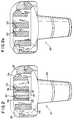
- Razor unit 10includes a seat portion 12, a cap portion 14 and ends 16, 18.
- the razor unitalso includes a vertically-displaceable seat blade 20 and a vertically-displaceable cap blade 22. Each of the blades includes a cutting edge extending along the longitudinal length of the blade.
- the razor unitincludes a vertically-displaceable guard bar 24 and shaving aids 26, 28 attached to the seat and cap portion, respectively.
- These shaving aidsmay be formed from various polymeric materials known to those in the shaving industry, e.g., polyethylene oxide, which has been found to provide desirable lubricity to shaving devices during wet-shaving.
- the guard bar, seat blade and cap bladeare supported on each end by laterally-disposed vertical return springs 30, which allow vertical displacement of the blades (and guard bar) in response to forces encountered during shaving and return the blades (and guard bar) to a resting position in the absence of any such forces.
- Laterally-disposed vertical return springs 30extend laterally from ends 16, 18 of wet-shaving razor unit 10 and, in a preferred embodiment, are continuous with such ends, as shown in Fig. 1.
- the seat and cap bladeseach include a vertically-disposed portion 32, 34, respectively and an angled portion 36, 38, respectively.
- the bladesare substantially encased in rectangular blocks 40, 42 of thermoplastic material.
- all of the vertically-disposed portion and the vast majority of the angled portion of each of the bladesis encased in such plastic. Only a part of the angled portion of the blades, which includes the cutting edge, extends outward from the rectangular block of plastic.
- guard bar 24is a continuous, thermoplastic body.
- razor unit 10'is similar in all respects to razor unit 10 except that blades 20' and 22' have been substituted for blades 20 and 22, respectively.
- Razor unit 10also includes a handle-receiving bracket 44 that engages with a chambered slot 46 formed in the bottom surface of the razor unit.
- the bracketas shown in Fig. 3, includes arms 48 configured to engage with a handle (not shown).
- a handlemay be designed to either fixedly maintain the razor unit or to allow “pivoting" of the razor unit during shaving. (The term “pivoting” refers to movement of the razor unit about an axis parallel to the cutting edge of the blade.)
- guard bar 24is partially broken away to show the laterally-disposed vertical return spring supporting the end of the encased seat blade.
- Each of the return springsis formed with a flexible hinge 50 to facilitate vertical displacement of the blades and guard bar. More particularly, assuming a force F is applied to the seat blade (as shown in Fig. 3), flexible hinge 50 will allow the encased seat blade to travel downward, i.e., towards bottom surface 52 of the razor unit, and will, additionally, return the encased seat blade to its "at rest" position after force F is removed.
- the encased cap bladeis identical in structure and design and need not be described separately.
- the bladeis substantially encased in plastic (i.e., in rectangular block 40) such that only a part of the blade, which includes the cutting edge, protrudes outward from the thermoplastic block.
- the cutting edgeis encased, in a "bump" 56 of thermoplastic material so that the corner tip of the blade, which is typically quite sharp, is not exposed to the user.
- this corner tipcould be "rounded off," thereby eliminating the need for encasing the cutting edge of the blade with a "bump" of plastic near its outer ends.
- the bladesare not encased in thermoplastic material along their entire length; instead, only the ends of the blades are encased with plastic, which is sufficient to both support the blade and provide a plastic body to which the return spring may be joined.
- the cutting edge of the blades near the blades outer endse.g., outer end 54
- the corner tipmay be "rounded off," thereby eliminating the need for encasing the cutting edge of the blade near its outer ends.
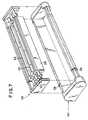
- an insert 58including seat blade 20, cap blade 22 and guard bar 24, is formed separate from the body or shell of the razor unit.
- Insert 58includes laterally-disposed vertical return springs 30, which function as described above. After insert 58 is formed, it is inserted into outer shell 60, which is fabricated separately and includes shaving aids 26, 28. Once assembled, the embodiment of Fig. 7 functions in the same manner as razor unit 10 illustrated in Fig. 1.
- a blade insert 62may be formed separate from the razor unit.
- Blade insert 62includes a rail 64, which is dimensioned to be received by a slot formed in the razor unit.
- a cap blade insert and a guard bar insertcould be formed in a similar manner.
- razor unit 10may include closure clips 66 for enclosing the ends of the razor unit.
- Closure clips 66may be employed with the present invention for the purpose of protecting return springs 30 during shaving.
- Closure clips 66may also be employed to apply a downwardly-directed force to the blades such the blades become upwardly biased.
- the present inventionincludes shaving aids 26, 28.
- shaving aid 26is positioned forward of the seat blade, while shaving aid 28 is positioned rearward of the cap blade.
- only one shaving aidcould be employed, such shaving aid being positioned in either of the indicated positions.
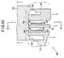
- the disclosed razor unitmay be formed through an insert molding procedure. Referring to Fig. 10, such an insert molding procedure will require a mold 68 having mold members 70, 72, 74 and 76.
- the mold membersshould be movable with respect to blades 20 and 22. For example, each of the mold members may be movable in the directions indicated in Fig. 10.
- the initial step of the insert molding procedurewill involve positioning the blades in the mold in proper orientation with respect to each other. In this regard, it may be necessary to support the blades at points along the vertically-disposed portion (i.e., portion 32 or 34). Following positioning of the blades, the mold members are moved into the position shown in Fig. 10. Mold members 70, 74 and 76 are configured to house the cutting edges of the blades during molding, thereby protecting such edges from the injected thermoplastic material.
- mold members 70 and 74are configured such that the cutting edge of blade 22 is sheltered by the mold members during molding. More particularly, the cutting edge is trapped between a triangular dimple 78 formed on mold member 70 and a chamfered edge 80 of mold member 74. As a result, the cutting edge is safely positioned within cavity 82 during the molding procedure. (The cutting edge of blade 20 is housed in a similar fashion during molding by mold members 70 and 76.)
- thermoplastic materialis injected into the mold.
- the thermoplastic materialfills the open areas of the mold (e.g., cavities 84, 86, 88 and 90 shown in Fig. 10) thereby forming the razor unit.
- a polymeric materialmay also be injected into the mold to form shaving aids 26, 28. After the thermoplastic material has set, the mold is opened and the formed razor unit is removed.
- mold 68includes additional mold members (e.g., mold member 92) that form vertical return springs 30.
- mold member 70is configured with a triangular protrusion 94.
- Opposite triangular protrusion 94is a triangular recess 96 formed in mold member 92.
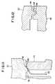
- the razor unitis simultaneously molded with handle-receiving bracket 44'. More particularly, bracket 44' is molded such that it is hinge mounted to the razor unit. After molding, bracket 44' is rotated clockwise about the hinge until the bracket engages chamfered slot 46'. Hinge 100 may or may not be subsequently discarded.
- the handle-receiving bracketi.e., bracket 44''
- the handle-receiving bracketis formed in two halves, one half being hinge mounted on each end of the razor unit, as shown in Fig. 14.
Landscapes
- Life Sciences & Earth Sciences (AREA)
- Forests & Forestry (AREA)
- Engineering & Computer Science (AREA)
- Mechanical Engineering (AREA)
- Dry Shavers And Clippers (AREA)
- Knives (AREA)
Abstract
Description
Claims (30)
- A head (10) for a wet shaving razor unit for shaving of a contouredsurface, comprising:at least one vertically displaceable blade (20,22) extending along thelength of the head;a blade mount (12,14,16,18); anda plurality of vertically acting springs (30) interconnecting the endsof the blade (20,22) and the mount (12,14,16,18), whereby movably tosupport the blade relative to the mount, characterised in that:i) the blade (20,22) includes a vertically disposed portion(32,34) and an angled portion (36,38) having a cutting edge for shaving,said vertically disposed portion (32,34) being encased in thermoplasticmaterial along the longitudinal length of the blade; andii) the vertically acting springs (30) are laterally disposed andare integrally formed and continuous with said thermoplastic material(40,42) encasing the vertically disposed portion (32,34) of the blade.
- A head according to Claim 1, wherein said vertically acting springs(20,22) are continuous with said ends (16,18) of said head (10).
- A head according to Claim 1 or Claim 2, wherein said cutting edgeof said blade (20,22) is encased with said thermoplastic material (40,42)at each of its outer ends.
- A head according to any one of Claims 1 to 3, wherein said angledportion (36,38) of said blade is substantially encased in said thermoplasticmaterial.
- A head according to Claim 4, wherein said cutting edge of said blade (20,22) extends outwardly from said encased angled portion (36,38)to allow shaving.
- A head according to Claim 1, wherein the outer ends of saidvertically-disposed portion (32,34) and said angled portion (36,38) areencased in thermoplastic material.
- A head according to Claim 6, wherein said encased outer ends areintegrally formed and continuous with said laterally-disposed verticalreturn springs (30).
- A head according to Claim 6 or 7, wherein the cutting edge of saidblade (20,22) is encased in said thermoplastic material at its outer end.
- A head according to any one of the preceding claims, wherein saidreturn springs (30) include a flexible hinge (50) for facilitating saidvertical displacement of said blade (20,22).
- A head according to any one of the preceding claims, furthercomprising at least one shaving aid (26,28) attached to a skin-engagingportion of said head.
- A head according to Claim 10, including a first shaving aid (26)and a second shaving aid (28), and wherein said first shaving aid (26) ispositioned forwardly of said blade (20) and said second shaving aid (28)is positioned rearwardly of said blade (22).
- A head according to Claim 10 or 11, wherein said shaving aid(26,28) is a polymeric material having at least one active ingredient.
- A head according to Claim 12, wherein said active ingredient ispolyethylene oxide.
- A head according to any one of the preceding claims, furthercomprising a handle-receiving bracket (44,44',44'') attached to said head.
- A head according to Claim 14, wherein said head includes engagingmeans for receipt of and engagement with said handle-receiving bracket(44,44',44'').
- A head according to any one of the preceding claims, including ahandle-receiving bracket (44,44',44''), and wherein said handle-receivingbracket is hinge mounted (100) to said head.
- A head according to any one of the preceding claims, furthercomprising closure clips (66) for enclosing the ends of said razor unit.
- A head according to Claim 17, wherein said blade is biased by saidclosure clips (66).
- A head according to Claim 18, wherein said closure clips (66)apply a downwardly-directed force to said blade such that said blade isupwardly biased.
- A head according to any one of the preceding claims, furthercomprising a vertically-displaceable guard bar (24) extending along thelength of said unit.
- A head according to any one of the preceding claims, including avertically-displaceable seat blade (20) and a vertically-displaceable cap blade (22).
- A wet-shaving razor for shaving of a contoured surface comprising:a head according to any preceding claim; anda shell configured to receive said head (10).
- A razor according to Claim 22, wherein said vertically actingsprings (30) are continuous with said ends of said head.
- The razor according to Claim 22 or Claim 23, wherein said returnsprings (30) allow vertical displacement of said blade (20,22) in responseto forces encountered during shaving and return said blade to a restingposition in the absence of said forces.
- A method of molding a head (10) for a wet-shaving razor according to claim 1,characterised in that during molding bothsides of the in-use vertically disposed portion of the blade are encasedalong the longitudinal length of the blade in thermoplastic material.
- The method according to Claim 25, further comprising the step ofproviding a shaving aid (27) to a skin-engaging portion of said head.
- The method according to Claim 25 or 26, further comprising thestep of molding a handle-receiving bracket (44,44',44'').
- The method according to Claim 27, wherein said bracket is moldedto said head in a hinged manner.
- The method according to any one of Claims 25 to 28, furthercomprising the step of positioning closure clips (66) on the ends of saidhead.
- The method according to any one of Claims 25 to 29, furthercomprising the step of forming a vertically-displaceable guard bar (24)extending along the length of said head.
Applications Claiming Priority (3)
| Application Number | Priority Date | Filing Date | Title |
|---|---|---|---|
| US97346892A | 1992-11-09 | 1992-11-09 | |
| US973468 | 1992-11-09 | ||
| PCT/US1993/010796WO1994011163A1 (en) | 1992-11-09 | 1993-11-08 | Insert molded dynamic shaving system |
Publications (2)
| Publication Number | Publication Date |
|---|---|
| EP0667813A1 EP0667813A1 (en) | 1995-08-23 |
| EP0667813B1true EP0667813B1 (en) | 1998-04-15 |
Family
ID=25520933
Family Applications (1)
| Application Number | Title | Priority Date | Filing Date |
|---|---|---|---|
| EP94900593AExpired - LifetimeEP0667813B1 (en) | 1992-11-09 | 1993-11-08 | Insert molded dynamic shaving system |
Country Status (8)
| Country | Link |
|---|---|
| US (1) | US5369885A (en) |
| EP (1) | EP0667813B1 (en) |
| JP (1) | JP3606869B2 (en) |
| KR (1) | KR950704095A (en) |
| AU (1) | AU5551994A (en) |
| CA (1) | CA2144437A1 (en) |
| DE (1) | DE69318035T2 (en) |
| WO (1) | WO1994011163A1 (en) |
Cited By (3)
| Publication number | Priority date | Publication date | Assignee | Title |
|---|---|---|---|---|
| US6839968B2 (en) | 2002-05-09 | 2005-01-11 | The Gillette Company | Shaving systems |
| US6852262B2 (en) | 2002-05-09 | 2005-02-08 | The Gillette Company | Insert molding razor cartridges |
| WO2006135668A1 (en)* | 2005-06-10 | 2006-12-21 | Eveready Battery Company, Inc. | Inter-blade guard and method for manufacturing same |
Families Citing this family (97)
| Publication number | Priority date | Publication date | Assignee | Title |
|---|---|---|---|---|
| US6161288A (en)* | 1993-02-22 | 2000-12-19 | Andrews; Edward A. | Four blade bi-directional razor structure with flexible guard system |
| US5903979A (en)* | 1994-07-13 | 1999-05-18 | The Gillette Company | Safety razors |
| GB9414092D0 (en)* | 1994-07-13 | 1994-08-31 | Gillette Co | Safety razors |
| WO1996010473A1 (en)* | 1994-10-03 | 1996-04-11 | The Gillette Company | Razor construction |
| US6298558B1 (en)* | 1994-10-31 | 2001-10-09 | The Gillette Company | Skin engaging member |
| US6295734B1 (en)* | 1995-03-23 | 2001-10-02 | The Gillette Company | Safety razors |
| US6185823B1 (en)* | 1995-11-10 | 2001-02-13 | The Gillette Company | Oval frame razor |
| USD393929S (en) | 1996-03-21 | 1998-04-28 | American Safety Razor Company | Razor blade assembly |
| US5711076A (en)* | 1996-03-27 | 1998-01-27 | The Gillette Company | Shaving system with improved guard structure |
| WO1997035693A2 (en)* | 1996-03-27 | 1997-10-02 | Warner-Lambert Company | Shaving system with uniform shaving forces |
| USD428532S (en)* | 1996-06-13 | 2000-07-18 | American Safety Razor Company | Safety razor cartridge |
| US6035537A (en)* | 1997-09-30 | 2000-03-14 | The Gillette Company | Razor cartridge with metal clip retaining blades |
| US6009624A (en)* | 1997-09-30 | 2000-01-04 | The Gillette Company | Razor cartridge with movable blades |
| US6115902A (en)* | 1998-02-13 | 2000-09-12 | Bic Corporation | Method of manufacturing a razor |
| USD429543S (en)* | 1998-04-22 | 2000-08-15 | Bic Corporation | Razor unit with lubricating strips |
| US20020000040A1 (en)* | 1998-12-21 | 2002-01-03 | The Gillette Company | Safety razors |
| US6145201A (en)* | 1999-07-27 | 2000-11-14 | Andrews; Edward A. | Underarm shaving devices |
| CA2391308A1 (en)* | 1999-07-27 | 2001-02-01 | Edward A. Andrews | Manual shaving razors with glides |
| US6216345B1 (en)* | 1999-07-27 | 2001-04-17 | Edward A. Andrews | Glide systems for manual shaving razors |
| GB2354474B8 (en)* | 1999-09-27 | 2008-01-29 | Gillette Co | Safety razors |
| KR100669144B1 (en)* | 1999-11-29 | 2007-01-15 | 코닌클리케 필립스 일렉트로닉스 엔.브이. | Shaver with shaving head with sub-frame and main frame |
| US6996908B2 (en) | 2000-02-16 | 2006-02-14 | Eveready Battery Company, Inc. | Wet shaving assembly |
| US7086159B2 (en)* | 2000-02-16 | 2006-08-08 | Eveready Battery Company, Inc. | Razor assembly |
| US20070180700A9 (en)* | 2000-02-16 | 2007-08-09 | Sandor James A | Composition for shaving aid material and shaving aid cartridge for shaving aid material |
| US7370419B2 (en) | 2000-02-16 | 2008-05-13 | Eveready Battery Company, Inc. | Replacement cartridge for a razor assembly |
| US6584690B2 (en)* | 2000-02-16 | 2003-07-01 | Warner-Lambert Company | Wet shaving assembly |
| GB2360479A (en)* | 2000-03-03 | 2001-09-26 | Enda Keaveney | Improvements in or relating to a razor |
| US7178241B1 (en) | 2000-05-22 | 2007-02-20 | Eveready Battery Company, Inc. | Lubricating shaving assembly |
| GB2375067A (en)* | 2001-05-01 | 2002-11-06 | Enda Keaveney | Razor |
| US7266895B2 (en)* | 2002-04-24 | 2007-09-11 | Eveready Battery Company, Inc. | Razor assembly |
| DE60330281D1 (en)* | 2002-04-24 | 2010-01-07 | Eveready Battery Inc | Cartridge with shaving aid for a shaving arrangement |
| US6948249B2 (en)* | 2002-07-17 | 2005-09-27 | Eveready Battery Company, Inc. | Razor cartridge with a shaving aid and a method of manufacturing a razor cartridge |
| US6763590B2 (en) | 2002-10-21 | 2004-07-20 | Eveready Battery Company, Inc. | Razor assembly having a clutch controlled shaving aid delivery system |
| US7162800B2 (en) | 2003-05-12 | 2007-01-16 | Eveready Battery Company, Inc. | Wet shaving assembly |
| US7617607B2 (en) | 2003-07-21 | 2009-11-17 | The Gillette Company | Shaving razors and other hair cutting assemblies |
| US7103976B2 (en) | 2004-02-06 | 2006-09-12 | Eveready Battery Company, Inc. | Razor assembly |
| US7272991B2 (en)* | 2004-02-09 | 2007-09-25 | The Gillette Company | Shaving razors, and blade subassemblies therefor and methods of manufacture |
| US7621203B2 (en) | 2004-02-09 | 2009-11-24 | The Gillette Company | Shaving razors, and blade subassemblies therefor and methods of manufacture |
| US20050188539A1 (en)* | 2004-02-26 | 2005-09-01 | Prudden John Jr. | Shaving blade unit |
| US7669335B2 (en) | 2004-03-11 | 2010-03-02 | The Gillette Company | Shaving razors and shaving cartridges |
| US7690122B2 (en) | 2004-03-11 | 2010-04-06 | The Gillette Company | Shaving razor with button |
| US7131202B2 (en) | 2004-03-11 | 2006-11-07 | The Gillette Company | Cutting members for shaving razors with multiple blades |
| US7168173B2 (en) | 2004-03-11 | 2007-01-30 | The Gillette Company | Shaving system |
| US7197825B2 (en) | 2004-03-11 | 2007-04-03 | The Gillette Company | Razors and shaving cartridges with guard |
| US20060080837A1 (en)* | 2004-10-20 | 2006-04-20 | Robert Johnson | Shaving razors and cartridges |
| US20110023307A1 (en)* | 2005-06-10 | 2011-02-03 | Eveready Battery Company, Inc. | Inter-Blade Guard and Method for Manufacturing Same |
| JP4950506B2 (en) | 2006-02-14 | 2012-06-13 | 株式会社貝印刃物開発センター | razor |
| JP4977374B2 (en) | 2006-02-14 | 2012-07-18 | 株式会社貝印刃物開発センター | razor |
| JP4950507B2 (en) | 2006-02-14 | 2012-06-13 | 株式会社貝印刃物開発センター | razor |
| EP2029329B1 (en)* | 2006-06-20 | 2011-03-02 | BIC Violex S.A. | Razor blade unit head and safety razor including such a blade unit |
| US20080256802A1 (en)* | 2007-04-20 | 2008-10-23 | O'connor William Thomas | Array of razor cartridges |
| US20080256800A1 (en)* | 2007-04-20 | 2008-10-23 | Roy Nicoll | Razor cartridge assembly with movable face |
| CA2711720A1 (en)* | 2008-01-11 | 2009-07-23 | The Gillette Company | Hair removal with fluid delivery |
| PL2276591T3 (en)* | 2008-05-05 | 2013-11-29 | Eveready Battery Inc | Method of making a razor blade |
| MX2011003331A (en)* | 2008-09-29 | 2011-04-26 | Gillette Co | Razors and razor cartridges with a decreased total interblade span. |
| EP2349658B1 (en)* | 2008-09-29 | 2013-03-06 | The Gillette Company | Razor cartridges with perforated blade assemblies |
| US8671577B2 (en)* | 2008-12-03 | 2014-03-18 | Thomas A. Brown | Razor with independent suspension |
| KR20110024234A (en)* | 2009-09-01 | 2011-03-09 | 주식회사 도루코 | Shaver cartridges |
| US20110203113A1 (en)* | 2010-02-25 | 2011-08-25 | Xiandong Wang | Razor Cartridge With Improved Cap Structure |
| US9694502B2 (en)* | 2010-10-27 | 2017-07-04 | The Gillette Company | Incorporating shaving aid elements on a razor cartridge |
| EP2537648B1 (en) | 2011-06-20 | 2016-04-20 | The Gillette Company | Razor cartridge with skin contact element |
| ES2429352T3 (en)* | 2011-06-21 | 2013-11-14 | The Gillette Company | Shaver cartridge with skin contact element |
| BR112014007708B1 (en) | 2011-10-06 | 2020-09-15 | Bic-Violex Sa | RIGID SHAVING OR SHAVING BLADE FORMED INTEGRALLY AND SHAVING OR SHAVING HEAD |
| US9283685B2 (en)* | 2012-07-26 | 2016-03-15 | Shavelogic, Inc. | Pivoting razors |
| RU2608929C2 (en)* | 2012-09-26 | 2017-01-26 | Бик-Вайолекс Са | Method and system for making assemblies |
| WO2014051842A1 (en) | 2012-09-27 | 2014-04-03 | Shavelogic, Inc. | Shaving systems |
| US9486930B2 (en) | 2012-09-27 | 2016-11-08 | Shavelogic, Inc. | Shaving systems |
| WO2014051843A1 (en) | 2012-09-28 | 2014-04-03 | Shavelogic, Inc. | Shaving systems |
| JP6093550B2 (en) | 2012-11-06 | 2017-03-08 | 株式会社貝印刃物開発センター | razor |
| EP2821190A4 (en)* | 2012-11-16 | 2015-11-04 | Xiangrong Ren | Razor head and razor |
| US9623575B2 (en) | 2012-12-18 | 2017-04-18 | Shavelogic, Inc. | Shaving systems |
| MX361581B (en)* | 2012-12-21 | 2018-12-11 | Bic Violex Sa | Shaver. |
| US20140366361A1 (en)* | 2013-06-17 | 2014-12-18 | The Gillette Company | Article for carrying a glide member for use with a razor |
| PL2853362T3 (en)* | 2013-09-25 | 2017-01-31 | Bic Violex S.A. | A shaving blade cartridge |
| US10421204B2 (en) | 2013-10-02 | 2019-09-24 | Dorco Co., Ltd. | Razor cartridges |
| US20150158192A1 (en) | 2013-12-09 | 2015-06-11 | Shavelogic, Inc. | Multi-material pivot return for shaving systems |
| USD850721S1 (en) | 2014-03-05 | 2019-06-04 | Mack-Ray, Inc. | Razor cartridge |
| WO2015142663A1 (en) | 2014-03-21 | 2015-09-24 | Shavelogic, Inc. | Metal spring return |
| US10960558B2 (en)* | 2014-07-11 | 2021-03-30 | Shavelogic, Inc. | Razor cartridges |
| EP3174674B1 (en) | 2014-07-31 | 2020-02-19 | Beiersdorf Aktiengesellschaft | Safety razor and blade unit for safety razor |
| WO2016028550A1 (en)* | 2014-08-20 | 2016-02-25 | Shavelogic, Inc. | Razor cartridges |
| CN107107359B (en)* | 2015-02-01 | 2020-07-10 | 麦凯瑞公司 | Double-sided razor |
| EP3072646B1 (en)* | 2015-03-25 | 2020-06-17 | The Gillette Company LLC | Shaving razor cartridge |
| RU2694395C1 (en)* | 2015-12-01 | 2019-07-12 | Бик-Виолекс Са | Shaving machines and cartridges |
| WO2017103881A1 (en)* | 2015-12-17 | 2017-06-22 | Bic Violex S.A. | Shaving head |
| EP3292963B1 (en)* | 2016-09-09 | 2020-04-01 | The Gillette Company LLC | Shaving razor cartridge |
| USD877983S1 (en) | 2016-09-09 | 2020-03-10 | The Gillette Company Llc | Shaving razor cartridge |
| EP3292965B1 (en)* | 2016-09-09 | 2021-05-26 | The Gillette Company LLC | Shaving razor cartridge and method of assembling |
| KR101746387B1 (en)* | 2016-11-24 | 2017-06-14 | 주식회사 도루코 | Unitary razor cartridge |
| US11117278B2 (en) | 2017-06-06 | 2021-09-14 | The Gillette Company Llc | Shaving razor cartridge |
| CN109262663A (en)* | 2018-11-29 | 2019-01-25 | 中山佐客护理用品有限公司 | Razor head and shaver |
| USD921984S1 (en) | 2019-03-19 | 2021-06-08 | The Gillette Company Llc | Shaving razor cartridge |
| US11235485B2 (en)* | 2019-04-23 | 2022-02-01 | Bic Violex S.A. | Shaving aid for retaining elements |
| EP4606539A2 (en)* | 2019-06-21 | 2025-08-27 | The Gillette Company LLC | Razor cartridge with one or more skin support elements |
| EP3865260B1 (en) | 2020-02-12 | 2024-01-03 | Edgewell Personal Care Brands, LLC | Razor cartridge |
| DE102020130698A1 (en)* | 2020-11-20 | 2022-05-25 | LORD International Co. | Blade unit for a wet razor |
| US12409574B2 (en) | 2021-03-12 | 2025-09-09 | Edgewell Personal Care Brands, Llc | Razor cartridge |
Family Cites Families (17)
| Publication number | Priority date | Publication date | Assignee | Title |
|---|---|---|---|---|
| GB1160542A (en)* | 1965-04-29 | 1969-08-06 | Wilkinson Sword Ltd | Improvements in and relating to Shaving Units and Dispensers Therefor |
| US3660893A (en)* | 1969-03-26 | 1972-05-09 | Norman C Welsh | Replaceable blade unit for a safety razor |
| US4184247A (en)* | 1978-09-07 | 1980-01-22 | The Gillette Company | Safety razor |
| DE3019399A1 (en)* | 1979-05-25 | 1981-04-23 | The Gillette Co., 02199 Boston, Mass. | HEAD OF A SAFETY SHAVER |
| US4378634A (en)* | 1979-12-07 | 1983-04-05 | The Gillette Company | Razor blade assembly |
| US4492024A (en)* | 1982-09-17 | 1985-01-08 | The Gillette Company | Razor blade assembly |
| GB2131337B (en)* | 1982-12-07 | 1985-10-30 | Gillette Co | Safety razors |
| US4554735A (en)* | 1984-05-04 | 1985-11-26 | Warner-Lambert Company | One-piece disposable razor |
| GB8710963D0 (en)* | 1987-05-08 | 1987-06-10 | Gillette Co | Safety razors |
| GB8712785D0 (en)* | 1987-06-01 | 1987-07-08 | Gillette Co | Blade units |
| DE8910491U1 (en)* | 1989-09-02 | 1991-01-10 | Wilkinson Sword GmbH, 5650 Solingen | Shaver head of a wet shaver |
| DE8910490U1 (en)* | 1989-09-02 | 1991-01-10 | Wilkinson Sword GmbH, 5650 Solingen | Shaver head of a wet shaver |
| AR244587A1 (en)* | 1989-11-17 | 1993-11-30 | Warner Lambert Co | Pivoting safety razor assembly |
| RU2097173C1 (en)* | 1990-06-11 | 1997-11-27 | Дзе Джиллет Компани | Safety razor |
| GB9013047D0 (en)* | 1990-06-12 | 1990-08-01 | Gillette Co | Safety razors |
| US5056222A (en)* | 1990-09-28 | 1991-10-15 | The Gillette Company | Shaving system |
| US5063667A (en)* | 1990-09-28 | 1991-11-12 | The Gillette Company | Shaving system |
- 1993
- 1993-11-08EPEP94900593Apatent/EP0667813B1/ennot_activeExpired - Lifetime
- 1993-11-08CACA002144437Apatent/CA2144437A1/ennot_activeAbandoned
- 1993-11-08AUAU55519/94Apatent/AU5551994A/ennot_activeAbandoned
- 1993-11-08JPJP51228794Apatent/JP3606869B2/ennot_activeExpired - Lifetime
- 1993-11-08DEDE69318035Tpatent/DE69318035T2/ennot_activeExpired - Lifetime
- 1993-11-08WOPCT/US1993/010796patent/WO1994011163A1/enactiveIP Right Grant
- 1993-11-08KRKR1019950701820Apatent/KR950704095A/ennot_activeWithdrawn
- 1994
- 1994-05-02USUS08/236,862patent/US5369885A/ennot_activeExpired - Lifetime
Cited By (5)
| Publication number | Priority date | Publication date | Assignee | Title |
|---|---|---|---|---|
| US6839968B2 (en) | 2002-05-09 | 2005-01-11 | The Gillette Company | Shaving systems |
| US6852262B2 (en) | 2002-05-09 | 2005-02-08 | The Gillette Company | Insert molding razor cartridges |
| WO2006135668A1 (en)* | 2005-06-10 | 2006-12-21 | Eveready Battery Company, Inc. | Inter-blade guard and method for manufacturing same |
| US7681314B2 (en) | 2005-06-10 | 2010-03-23 | Eveready Battery Company Inc. | Inter-blade guard and method for manufacturing same |
| EP2272639A1 (en)* | 2005-06-10 | 2011-01-12 | Eveready Battery Company, Inc. | Razor cartridge with inter-blade guard |
Also Published As
| Publication number | Publication date |
|---|---|
| US5369885A (en) | 1994-12-06 |
| JP3606869B2 (en) | 2005-01-05 |
| WO1994011163A1 (en) | 1994-05-26 |
| AU5551994A (en) | 1994-06-08 |
| DE69318035T2 (en) | 1998-10-15 |
| EP0667813A1 (en) | 1995-08-23 |
| CA2144437A1 (en) | 1994-05-26 |
| DE69318035D1 (en) | 1998-05-20 |
| KR950704095A (en) | 1995-11-17 |
| JPH08503399A (en) | 1996-04-16 |
Similar Documents
| Publication | Publication Date | Title |
|---|---|---|
| EP0667813B1 (en) | Insert molded dynamic shaving system | |
| EP0462807B1 (en) | Process for insert molding wet-shaving razor unit and unit made therefrom | |
| EP1537964B1 (en) | Razor heads with intermediate guard elements | |
| US7200937B2 (en) | Razor head with moveable blade package | |
| US5410810A (en) | Safety razors | |
| US4932123A (en) | Improvements in or relating to safety razors | |
| US5813119A (en) | Razors which actively flex a razor head in response to shaving forces | |
| EP0817706B1 (en) | Two-axis pivoting shaving system | |
| EP0166617B1 (en) | One-piece disposable razor with blade protector | |
| EP0522071B1 (en) | Safety razors and blade units therefor | |
| EP0288301B1 (en) | A method for making a razor | |
| US5318429A (en) | Process for insert molding wet-shaving razor unit and unit made therefrom | |
| US4679324A (en) | Safety razor blades | |
| JP3117711B2 (en) | Safety razor | |
| EP0470720B1 (en) | One-piece flexible razor head | |
| WO1995025617A1 (en) | Insert molded dynamic opposing blade shaving system | |
| EP0289228B1 (en) | A method of making a razor | |
| EP0655027B1 (en) | Shaving aid with increased flexibility | |
| KR200184865Y1 (en) | Cover opening structure of razor |
Legal Events
| Date | Code | Title | Description |
|---|---|---|---|
| PUAI | Public reference made under article 153(3) epc to a published international application that has entered the european phase | Free format text:ORIGINAL CODE: 0009012 | |
| 17P | Request for examination filed | Effective date:19950324 | |
| AK | Designated contracting states | Kind code of ref document:A1 Designated state(s):DE ES FR GB IT | |
| 17Q | First examination report despatched | Effective date:19951222 | |
| GRAG | Despatch of communication of intention to grant | Free format text:ORIGINAL CODE: EPIDOS AGRA | |
| GRAG | Despatch of communication of intention to grant | Free format text:ORIGINAL CODE: EPIDOS AGRA | |
| GRAH | Despatch of communication of intention to grant a patent | Free format text:ORIGINAL CODE: EPIDOS IGRA | |
| GRAH | Despatch of communication of intention to grant a patent | Free format text:ORIGINAL CODE: EPIDOS IGRA | |
| GRAA | (expected) grant | Free format text:ORIGINAL CODE: 0009210 | |
| AK | Designated contracting states | Kind code of ref document:B1 Designated state(s):DE ES FR GB IT | |
| PG25 | Lapsed in a contracting state [announced via postgrant information from national office to epo] | Ref country code:IT Free format text:LAPSE BECAUSE OF FAILURE TO SUBMIT A TRANSLATION OF THE DESCRIPTION OR TO PAY THE FEE WITHIN THE PRE;WARNING: LAPSES OF ITALIAN PATENTS WITH EFFECTIVE DATE BEFORE 2007 MAY HAVE OCCURRED AT ANY TIME BEFORE 2007. THE CORRECT EFFECTIVE DATE MAY BE DIFFERENT FROM THE ONE RECORDED.SCRIBED TIME-LIMIT Effective date:19980415 Ref country code:ES Free format text:THE PATENT HAS BEEN ANNULLED BY A DECISION OF A NATIONAL AUTHORITY Effective date:19980415 | |
| REF | Corresponds to: | Ref document number:69318035 Country of ref document:DE Date of ref document:19980520 | |
| ET | Fr: translation filed | ||
| PLBE | No opposition filed within time limit | Free format text:ORIGINAL CODE: 0009261 | |
| STAA | Information on the status of an ep patent application or granted ep patent | Free format text:STATUS: NO OPPOSITION FILED WITHIN TIME LIMIT | |
| 26N | No opposition filed | ||
| REG | Reference to a national code | Ref country code:GB Ref legal event code:IF02 | |
| PGFP | Annual fee paid to national office [announced via postgrant information from national office to epo] | Ref country code:FR Payment date:20041119 Year of fee payment:12 | |
| PG25 | Lapsed in a contracting state [announced via postgrant information from national office to epo] | Ref country code:FR Free format text:LAPSE BECAUSE OF NON-PAYMENT OF DUE FEES Effective date:20060731 | |
| REG | Reference to a national code | Ref country code:FR Ref legal event code:ST Effective date:20060731 | |
| PGFP | Annual fee paid to national office [announced via postgrant information from national office to epo] | Ref country code:DE Payment date:20121128 Year of fee payment:20 | |
| PGFP | Annual fee paid to national office [announced via postgrant information from national office to epo] | Ref country code:GB Payment date:20121126 Year of fee payment:20 | |
| REG | Reference to a national code | Ref country code:DE Ref legal event code:R071 Ref document number:69318035 Country of ref document:DE | |
| REG | Reference to a national code | Ref country code:GB Ref legal event code:PE20 Expiry date:20131107 | |
| PG25 | Lapsed in a contracting state [announced via postgrant information from national office to epo] | Ref country code:DE Free format text:LAPSE BECAUSE OF EXPIRATION OF PROTECTION Effective date:20131109 Ref country code:GB Free format text:LAPSE BECAUSE OF EXPIRATION OF PROTECTION Effective date:20131107 |