EP0667324A1 - Ferroelectric aerogel composites for voltage-variable dielectric tuning, and method for making the same - Google Patents
Ferroelectric aerogel composites for voltage-variable dielectric tuning, and method for making the sameDownload PDFInfo
- Publication number
- EP0667324A1 EP0667324A1EP95101957AEP95101957AEP0667324A1EP 0667324 A1EP0667324 A1EP 0667324A1EP 95101957 AEP95101957 AEP 95101957AEP 95101957 AEP95101957 AEP 95101957AEP 0667324 A1EP0667324 A1EP 0667324A1
- Authority
- EP
- European Patent Office
- Prior art keywords
- ferroelectric
- gel
- aerogel
- composite
- water
- Prior art date
- Legal status (The legal status is an assumption and is not a legal conclusion. Google has not performed a legal analysis and makes no representation as to the accuracy of the status listed.)
- Granted
Links
- 239000004964aerogelSubstances0.000titleclaimsabstractdescription63
- 239000002131composite materialSubstances0.000titleclaimsabstractdescription52
- 238000000034methodMethods0.000titleclaimsabstractdescription33
- 239000011148porous materialSubstances0.000claimsabstractdescription36
- 229920000642polymerPolymers0.000claimsabstractdescription22
- 229910002113barium titanateInorganic materials0.000claimsabstractdescription3
- XLYOFNOQVPJJNP-UHFFFAOYSA-NwaterSubstancesOXLYOFNOQVPJJNP-UHFFFAOYSA-N0.000claimsdescription26
- 239000002904solventSubstances0.000claimsdescription21
- 239000000463materialSubstances0.000claimsdescription15
- 229910052751metalInorganic materials0.000claimsdescription15
- 239000002184metalSubstances0.000claimsdescription15
- 239000007789gasSubstances0.000claimsdescription12
- LFQSCWFLJHTTHZ-UHFFFAOYSA-NEthanolChemical compoundCCOLFQSCWFLJHTTHZ-UHFFFAOYSA-N0.000claimsdescription9
- 239000006260foamSubstances0.000claimsdescription8
- 238000010438heat treatmentMethods0.000claimsdescription8
- 239000012530fluidSubstances0.000claimsdescription7
- 238000004519manufacturing processMethods0.000claimsdescription7
- 150000002739metalsChemical class0.000claimsdescription5
- 238000005245sinteringMethods0.000claimsdescription5
- 229910052712strontiumInorganic materials0.000claimsdescription5
- 229910052788bariumInorganic materials0.000claimsdescription4
- 238000011067equilibrationMethods0.000claimsdescription4
- 229910010252TiO3Inorganic materials0.000claimsdescription3
- 238000011049fillingMethods0.000claimsdescription3
- 230000003301hydrolyzing effectEffects0.000claimsdescription3
- 239000011261inert gasSubstances0.000claimsdescription3
- 238000005470impregnationMethods0.000claims2
- 229910002370SrTiO3Inorganic materials0.000claims1
- 229910052454barium strontium titanateInorganic materials0.000abstractdescription13
- 239000000203mixtureSubstances0.000abstractdescription8
- 238000003980solgel methodMethods0.000abstractdescription2
- JRPBQTZRNDNNOP-UHFFFAOYSA-Nbarium titanateChemical compound[Ba+2].[Ba+2].[O-][Ti]([O-])([O-])[O-]JRPBQTZRNDNNOP-UHFFFAOYSA-N0.000abstract1
- 239000011222crystalline ceramicSubstances0.000abstract1
- 229910002106crystalline ceramicInorganic materials0.000abstract1
- 238000000194supercritical-fluid extractionMethods0.000abstract1
- CURLTUGMZLYLDI-UHFFFAOYSA-NCarbon dioxideChemical compoundO=C=OCURLTUGMZLYLDI-UHFFFAOYSA-N0.000description28
- 239000000499gelSubstances0.000description25
- 229910002092carbon dioxideInorganic materials0.000description14
- 239000001569carbon dioxideSubstances0.000description14
- 239000000919ceramicSubstances0.000description8
- 238000013459approachMethods0.000description6
- 230000005684electric fieldEffects0.000description6
- 238000002360preparation methodMethods0.000description6
- 239000004793PolystyreneSubstances0.000description5
- 229920002223polystyrenePolymers0.000description5
- CSCPPACGZOOCGX-UHFFFAOYSA-NAcetoneChemical compoundCC(C)=OCSCPPACGZOOCGX-UHFFFAOYSA-N0.000description4
- IJGRMHOSHXDMSA-UHFFFAOYSA-NAtomic nitrogenChemical compoundN#NIJGRMHOSHXDMSA-UHFFFAOYSA-N0.000description4
- 238000007792additionMethods0.000description4
- 239000000945fillerSubstances0.000description4
- 239000007788liquidSubstances0.000description4
- 238000002156mixingMethods0.000description4
- 239000002245particleSubstances0.000description4
- -1strontium metalsChemical class0.000description4
- 229910002938(Ba,Sr)TiO3Inorganic materials0.000description3
- XNWFRZJHXBZDAG-UHFFFAOYSA-N2-METHOXYETHANOLChemical compoundCOCCOXNWFRZJHXBZDAG-UHFFFAOYSA-N0.000description3
- OKKJLVBELUTLKV-UHFFFAOYSA-NMethanolChemical compoundOCOKKJLVBELUTLKV-UHFFFAOYSA-N0.000description3
- DSAJWYNOEDNPEQ-UHFFFAOYSA-Nbarium atomChemical compound[Ba]DSAJWYNOEDNPEQ-UHFFFAOYSA-N0.000description3
- 239000011230binding agentSubstances0.000description3
- 238000004814ceramic processingMethods0.000description3
- 238000000605extractionMethods0.000description3
- 239000012535impuritySubstances0.000description3
- 239000003999initiatorSubstances0.000description3
- 239000000178monomerSubstances0.000description3
- 238000003809water extractionMethods0.000description3
- XKRFYHLGVUSROY-UHFFFAOYSA-NArgonChemical compound[Ar]XKRFYHLGVUSROY-UHFFFAOYSA-N0.000description2
- XPDWGBQVDMORPB-UHFFFAOYSA-NFluoroformChemical compoundFC(F)FXPDWGBQVDMORPB-UHFFFAOYSA-N0.000description2
- GQPLMRYTRLFLPF-UHFFFAOYSA-NNitrous OxideChemical compound[O-][N+]#NGQPLMRYTRLFLPF-UHFFFAOYSA-N0.000description2
- VYPSYNLAJGMNEJ-UHFFFAOYSA-NSilicium dioxideChemical compoundO=[Si]=OVYPSYNLAJGMNEJ-UHFFFAOYSA-N0.000description2
- RTAQQCXQSZGOHL-UHFFFAOYSA-NTitaniumChemical compound[Ti]RTAQQCXQSZGOHL-UHFFFAOYSA-N0.000description2
- 238000002441X-ray diffractionMethods0.000description2
- MCMNRKCIXSYSNV-UHFFFAOYSA-NZirconium dioxideChemical compoundO=[Zr]=OMCMNRKCIXSYSNV-UHFFFAOYSA-N0.000description2
- 238000004458analytical methodMethods0.000description2
- 230000015556catabolic processEffects0.000description2
- 238000009826distributionMethods0.000description2
- 230000000694effectsEffects0.000description2
- 238000001914filtrationMethods0.000description2
- 238000001879gelationMethods0.000description2
- 238000000227grindingMethods0.000description2
- 230000008595infiltrationEffects0.000description2
- 238000001764infiltrationMethods0.000description2
- 238000012986modificationMethods0.000description2
- 230000004048modificationEffects0.000description2
- 229910052757nitrogenInorganic materials0.000description2
- 239000000047productSubstances0.000description2
- 238000012216screeningMethods0.000description2
- 238000000926separation methodMethods0.000description2
- CIOAGBVUUVVLOB-UHFFFAOYSA-Nstrontium atomChemical compound[Sr]CIOAGBVUUVVLOB-UHFFFAOYSA-N0.000description2
- 239000010936titaniumSubstances0.000description2
- 229910052719titaniumInorganic materials0.000description2
- VXUYXOFXAQZZMF-UHFFFAOYSA-Ntitanium(IV) isopropoxideChemical compoundCC(C)O[Ti](OC(C)C)(OC(C)C)OC(C)CVXUYXOFXAQZZMF-UHFFFAOYSA-N0.000description2
- 238000003828vacuum filtrationMethods0.000description2
- 239000004342Benzoyl peroxideSubstances0.000description1
- OMPJBNCRMGITSC-UHFFFAOYSA-NBenzoylperoxideChemical compoundC=1C=CC=CC=1C(=O)OOC(=O)C1=CC=CC=C1OMPJBNCRMGITSC-UHFFFAOYSA-N0.000description1
- 239000004698PolyethyleneSubstances0.000description1
- 239000004721Polyphenylene oxideSubstances0.000description1
- 239000004743PolypropyleneSubstances0.000description1
- 229910018503SF6Inorganic materials0.000description1
- 150000001298alcoholsChemical class0.000description1
- PNEYBMLMFCGWSK-UHFFFAOYSA-Naluminium oxideInorganic materials[O-2].[O-2].[O-2].[Al+3].[Al+3]PNEYBMLMFCGWSK-UHFFFAOYSA-N0.000description1
- 229910052786argonInorganic materials0.000description1
- 235000019400benzoyl peroxideNutrition0.000description1
- 230000003247decreasing effectEffects0.000description1
- 238000000280densificationMethods0.000description1
- 239000002274desiccantSubstances0.000description1
- 230000001627detrimental effectEffects0.000description1
- 238000011161developmentMethods0.000description1
- 238000010586diagramMethods0.000description1
- 230000005672electromagnetic fieldEffects0.000description1
- 230000005670electromagnetic radiationEffects0.000description1
- 238000001704evaporationMethods0.000description1
- 230000008020evaporationEffects0.000description1
- 239000012467final productSubstances0.000description1
- 238000010304firingMethods0.000description1
- 238000007654immersionMethods0.000description1
- 229910021645metal ionInorganic materials0.000description1
- 238000009768microwave sinteringMethods0.000description1
- 238000003801millingMethods0.000description1
- 238000012544monitoring processMethods0.000description1
- 239000001272nitrous oxideSubstances0.000description1
- 231100000252nontoxicToxicity0.000description1
- 230000003000nontoxic effectEffects0.000description1
- 239000003960organic solventSubstances0.000description1
- 239000004417polycarbonateSubstances0.000description1
- 229920000515polycarbonatePolymers0.000description1
- 229920000573polyethylenePolymers0.000description1
- 229920006380polyphenylene oxidePolymers0.000description1
- 229920001155polypropylenePolymers0.000description1
- 239000000843powderSubstances0.000description1
- 238000003825pressingMethods0.000description1
- 230000001902propagating effectEffects0.000description1
- 230000005855radiationEffects0.000description1
- 239000000376reactantSubstances0.000description1
- 238000010992refluxMethods0.000description1
- 239000013557residual solventSubstances0.000description1
- 239000000377silicon dioxideSubstances0.000description1
- 238000003860storageMethods0.000description1
- SFZCNBIFKDRMGX-UHFFFAOYSA-Nsulfur hexafluorideChemical compoundFS(F)(F)(F)(F)FSFZCNBIFKDRMGX-UHFFFAOYSA-N0.000description1
- 229960000909sulfur hexafluorideDrugs0.000description1
- 125000000999tert-butyl groupChemical group[H]C([H])([H])C(*)(C([H])([H])[H])C([H])([H])[H]0.000description1
- 230000009466transformationEffects0.000description1
- 238000011282treatmentMethods0.000description1
Images

Classifications
- C—CHEMISTRY; METALLURGY
- C04—CEMENTS; CONCRETE; ARTIFICIAL STONE; CERAMICS; REFRACTORIES
- C04B—LIME, MAGNESIA; SLAG; CEMENTS; COMPOSITIONS THEREOF, e.g. MORTARS, CONCRETE OR LIKE BUILDING MATERIALS; ARTIFICIAL STONE; CERAMICS; REFRACTORIES; TREATMENT OF NATURAL STONE
- C04B35/00—Shaped ceramic products characterised by their composition; Ceramics compositions; Processing powders of inorganic compounds preparatory to the manufacturing of ceramic products
- C04B35/01—Shaped ceramic products characterised by their composition; Ceramics compositions; Processing powders of inorganic compounds preparatory to the manufacturing of ceramic products based on oxide ceramics
- C04B35/46—Shaped ceramic products characterised by their composition; Ceramics compositions; Processing powders of inorganic compounds preparatory to the manufacturing of ceramic products based on oxide ceramics based on titanium oxides or titanates
- C04B35/462—Shaped ceramic products characterised by their composition; Ceramics compositions; Processing powders of inorganic compounds preparatory to the manufacturing of ceramic products based on oxide ceramics based on titanium oxides or titanates based on titanates
- C04B35/465—Shaped ceramic products characterised by their composition; Ceramics compositions; Processing powders of inorganic compounds preparatory to the manufacturing of ceramic products based on oxide ceramics based on titanium oxides or titanates based on titanates based on alkaline earth metal titanates
- C04B35/47—Shaped ceramic products characterised by their composition; Ceramics compositions; Processing powders of inorganic compounds preparatory to the manufacturing of ceramic products based on oxide ceramics based on titanium oxides or titanates based on titanates based on alkaline earth metal titanates based on strontium titanates
- C—CHEMISTRY; METALLURGY
- C04—CEMENTS; CONCRETE; ARTIFICIAL STONE; CERAMICS; REFRACTORIES
- C04B—LIME, MAGNESIA; SLAG; CEMENTS; COMPOSITIONS THEREOF, e.g. MORTARS, CONCRETE OR LIKE BUILDING MATERIALS; ARTIFICIAL STONE; CERAMICS; REFRACTORIES; TREATMENT OF NATURAL STONE
- C04B35/00—Shaped ceramic products characterised by their composition; Ceramics compositions; Processing powders of inorganic compounds preparatory to the manufacturing of ceramic products
- C04B35/01—Shaped ceramic products characterised by their composition; Ceramics compositions; Processing powders of inorganic compounds preparatory to the manufacturing of ceramic products based on oxide ceramics
- C04B35/46—Shaped ceramic products characterised by their composition; Ceramics compositions; Processing powders of inorganic compounds preparatory to the manufacturing of ceramic products based on oxide ceramics based on titanium oxides or titanates
- C04B35/462—Shaped ceramic products characterised by their composition; Ceramics compositions; Processing powders of inorganic compounds preparatory to the manufacturing of ceramic products based on oxide ceramics based on titanium oxides or titanates based on titanates
- C04B35/465—Shaped ceramic products characterised by their composition; Ceramics compositions; Processing powders of inorganic compounds preparatory to the manufacturing of ceramic products based on oxide ceramics based on titanium oxides or titanates based on titanates based on alkaline earth metal titanates
- C04B35/468—Shaped ceramic products characterised by their composition; Ceramics compositions; Processing powders of inorganic compounds preparatory to the manufacturing of ceramic products based on oxide ceramics based on titanium oxides or titanates based on titanates based on alkaline earth metal titanates based on barium titanates
- C04B35/4682—Shaped ceramic products characterised by their composition; Ceramics compositions; Processing powders of inorganic compounds preparatory to the manufacturing of ceramic products based on oxide ceramics based on titanium oxides or titanates based on titanates based on alkaline earth metal titanates based on barium titanates based on BaTiO3 perovskite phase
- C—CHEMISTRY; METALLURGY
- C04—CEMENTS; CONCRETE; ARTIFICIAL STONE; CERAMICS; REFRACTORIES
- C04B—LIME, MAGNESIA; SLAG; CEMENTS; COMPOSITIONS THEREOF, e.g. MORTARS, CONCRETE OR LIKE BUILDING MATERIALS; ARTIFICIAL STONE; CERAMICS; REFRACTORIES; TREATMENT OF NATURAL STONE
- C04B35/00—Shaped ceramic products characterised by their composition; Ceramics compositions; Processing powders of inorganic compounds preparatory to the manufacturing of ceramic products
- C04B35/622—Forming processes; Processing powders of inorganic compounds preparatory to the manufacturing of ceramic products
- C04B35/624—Sol-gel processing
Definitions
- the present inventionrelates to ferroelectric composites, and more particularly, to a method for preparing such composites employing sol-gels.
- ferroelectric ceramics with voltage-tunable dielectric properties for electronically-scanned array (ESA) antenna applicationshas been severely limited due to a lack of suitable fabricated materials.
- the properties needed for these applications at high frequenciesinclude a low dielectric constant (less than about 100), a low loss tangent tan ⁇ (less than about 0.010), a large electric field-induced change in refractive index (ranging from 0.25 to 1.2) with a maximum applied electric field of less than 50 kV/cm, and a high dielectric breakdown strength (about 80,000 to 100,000 V/cm).
- Compositeshave been under development with the idea of achieving a low-loss tangent by impregnating a porous structure with a low-loss polymer. These methods have involved the preparation of a ceramic powder, mixing it with a binder, burning out the binder to achieve a porous structure, sintering (firing), and then infiltrating the structure with a polymer.
- the difficulty with this conventional approachis that the homogeneity of the microstructure and resulting dielectric properties are not controllable within the desired limits of ⁇ 2%rms.
- the polymer-impregnated ferroelectric compositeexhibits loss at the operational frequencies, which is due, in part, to the presence of impurities introduced by conventional ceramic processing.
- Prior art approaches to provide materials with voltage-variable dielectric propertiesinclude two basic methods, neither of which is entirely satisfactory for the high-frequency ESA antennas.
- One methodinvolves the use of porous ferroelectrics such as barium strontium titanate ((Ba,Sr)TiO3; BST).
- BSTbarium strontium titanate
- the porous BSTsuffers from the separation of the individual particles with higher pore volumes and intrinsic difficulty in achieving a homogenous microstructure which controls the range of resulting dielectric properties.
- the separation of the individual particlesis described as a lack of "connectivity", which is a term used to describe the degree of touching or connection between the particles.
- the other method of achieving some electric field-induced change in refractive indexis that of employing a honeycomb, or similarly structured, composite.
- the difficulty with this methodis that the pores are relatively quite large, so that the effective range is limited to lower frequencies, less than about 5 GHz.
- a ferroelectric composite having a controlled, small-pore sizeis required, together with a process for making the same, for use at higher frequencies, on the order of 10 to 80 GHz.
- a ferroelectric ceramic having a very uniform, small-pore size microstructure having a high porosityis provided.
- the pores of the ferroelectric ceramicare filled with an appropriate polymer to provide a novel ferroelectric composite.
- the minimum pore size within the compositedepends upon the maximum operating frequency for the ESA antenna.
- the pores (and other scattering centers) in the ferroelectric aerogel compositeshould be small enough so that the diameter d of these centers is bounded by the following expression: d ⁇ 0.05 c ⁇ ⁇ c , where c is the speed of light, ⁇ is the operating frequency and ⁇ c is the real part of the dielectric constant of the composite.
- the porosity of the ferroelectric aerogelcan be as high as 98%, which exceeds the porosity of prior art materials by 20 to 30%.
- ferroelectric materials beneficially treated in accordance with the inventionare the perovskites, which are characterized by the formula ABO3.
- ferroelectric perovskitesinclude BaTiO3 and (Ba,-Sr)TiO3.
- the ferroelectric composite of the present inventionis provided by a sol-gel derived aerogel preparation process.
- the processcomprises:
- the final productcomprising a porous ferroelectric material whose pores are filled with a low ( ⁇ 3) dielectric constant polymer, is characterized by a pore size depending on the maximum operational frequency of the ESA antenna and the real part of the dielectric constant of the material, as set forth in Eqn. (1), above. If the operational frequency is 94 GHz and the dielectric constant is 30, then the pore size can be no greater than 30 ⁇ m. The maximum pore size distribution should be less than 30 ⁇ m.
- the porositydepends on the dielectric constant and loss tangent sought for the polymer-infiltrated aerogel composite. High/low porosity yields low/high values for the dielectric constant and loss tangent. As a rule, the porosity should be greater than 80% for aerogel composites made from ferroelectric perovskites.
- the present inventionovercomes the difficulties associated with the prior art through the use of the sol-gel derived aerogel preparation process.
- Fabrication of the ferroelectric ceramic using the aerogel routepermits preparation of a very uniform, small-pore size microstructure material which can be formed into the desired shape.
- the processeliminates many conventional ceramic processing steps which introduce impurities, such as milling, grinding, binder addition, mixing, screening, and pressing.
- the sol-gel process for fabricating aerogelspermits fabrication of an ultra-pure finished product.
- the high purity together with the very small pore sizeprovides a means of achieving low loss at high frequencies.
- the ferroelectric aerogel composite of the present inventionovercomes the lack of interconnectivity associated with prior art structures at porosities greater than 70 to 80% with a fully connected aerogel structure.
- the homogeneity problem of prior art porous BSTis eliminated by the very uniform micro-pore aerogels.
- the aerogel process of the present inventionprevents impurities from entering the micro-structure.
- the ferroelectric aerogel composite microporesminimize the scattering of microwave and millimeter-wave radiation to allow its use at frequencies of interest (10 to 80 GHz), beyond the range of the honeycomb composites.
- the ferroelectric aerogel composite of the present inventionprovides a means for the intrinsic non-linear characteristics of some ferroelectric ceramics to be exploited for microwave antennas and other applications.
- An analysis of the dielectric properties of the ferroelectric aerogel compositewill be given first, followed by a description of their fabrication by the methods of the present invention.
- the important dielectric properties of a two-phase ferroelectric aerogel compositeare (1) the real permittivity, or real part of the dielectric constant, ⁇ c ; (2) the loss tangent, tan ⁇ ; (3) the fractional tunability T c ; (4) the scan figure-of-merit, SFM c ; and (5) the loss or attenuation ⁇ c .
- the equations defining these propertiesare described below.
- T c
- / ⁇ c
- is the change in permittivity from zero voltage bias to maximum applied dc bias.
- is the change in permittivity from zero voltage bias to maximum applied dc bias.
- is the change in permittivity from zero voltage bias to maximum applied dc bias.
- ⁇ ( dB / cm )3.41 ⁇ ⁇ ( cm ) ⁇ c tan ⁇ c , where ⁇ (cm) is the wavelength of the electromagnetic wave in a vacuum.
- the inclusions in the ferroelectric aerogel compositeshould be small enough so that the electromagnetic wave at the frequency or wavelength of interest is not scattered by these inclusions.
- the inclusion sizecan be no greater than about 6 ⁇ m. This upper bound increases with decreasing frequency.
- Submicrometer pore sizes and inclusionscan be easily achieved using the aerogel approach to fabricating ferroelectric composites.
- a ferroelectric aerogelis connected almost by definition.
- the aerogel approachestablishes connectivity at the atomic and/or molecular level through solution-gelation chemistry.
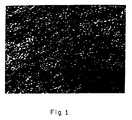
- FIG. 1illustrates the skeletal aerogel connectivity. Specifically, FIG. 1 shows the aerogel impregnated with polystyrene.
- the ferroelectric aerogel composite of the present inventioncan be fabricated using an aerogel preparation process shown in the flow chart in FIG. 2. Preparation of aerogels in the past has been limited largely to silica, alumina, and zirconia.
- the processavoids the contaminating activities of crushing, grinding, and screening of conventional ceramic processing.
- the process of the present inventionbroadly comprises:
- an alcoholate solution of the metals in the desired proportionsis provided.
- titaniuma commercial form of titanium isopropoxide is available, and may be employed in the practice of the invention.
- the alcoholate solutionis prepared by dissolving barium and strontium metals in 2-methoxyethanol [step 1].
- the titanium alcoholateis added to the barium/strontium alcoholate solution [step 2].
- the reactantsare subjected to an equilibration, such as refluxing for several hours, e.g., 2 to 8 hours, in a reactor at 135°C under nitrogen to form an equilibrated solution of the metal alcoholates [step 3].
- the equilibrated solutionis poured into a mold which has the shape of the desired final composite and a stoichiometric or greater amount of water is added [step 4].
- the amount of wateris based on the concentration of the metal ions.
- the watermust be diluted by adding one part 2-methoxyethanol to three parts water (by volume) prior to addition to the equilibrated solution to assure uniform gelation.
- the moldmust be sealed with an air-tight lid to prevent evaporation of the solvent during curing. Gels may be cured slowly (1 to 10 days) at room temperature or quickly at elevated temperature (1 to 60 min at 60°C). Larger additions of water also accelerate gel times.
- the gelis then treated, first to remove excess water, and then to remove the solvent.
- the treatmentmust be carried out in such a manner that the capillary forces from the solvent and water are not allowed to collapse the porous structure.
- the water in the gelis extracted by immersing the mold in a large excess of anhydrous solvent [step 5].
- the volume of solventmust be large enough to reduce the residual water content of the gel to less than 0.1% by weight.
- the solventmay be an alcohol or other organic solvent which is miscible with water and is also readily soluble in liquid carbon dioxide. Examples of such solvents include methanol, ethanol, 2-methoxyethanol, and acetone. Acetone is preferred, since it has a low solubility for partially hydrolyzed alcoholates.
- the moldcan be placed in a smaller amount of the solvent to which sufficient desiccant has been added to absorb the water. The time required for water extraction depends on the thickness of the gel.
- Thin samples on the order of 1 millimetermay be exchanged in a few hours. Thicker samples on the order of a few centimeters may be exchanged in a few days. Faster extraction times may be achieved if the mold can be designed such that vacuum filtration can be used to draw solvent through the gel and flush out residual water.
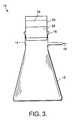
- FIG. 3depicts an example of apparatus 10 suitably employed in the water-extraction step.
- the apparatus 10comprises a vacuum filtration flask 12 provided with an opening 14 and an outlet 16 .
- the opening 14is sealed against the atmosphere with a rubber stopper 18 , in which a filter funnel 20 is placed, containing the cured sol-gel 22 .
- Anhydrous solvent 24is contained in the top of the filter funnel 20 .
- the outlet 16is connected to a source of vacuum (not shown), such as a vacuum pump.
- Forming a vacuum in the filtration flask 12draws the anhydrous solvent 24 through the sol-gel 22 , displacing water in its pores.
- the water, which is removed from the sol-gel 22 until there is less than 0.1% by weight in the sol-gelis collected in the filtration flask 12 .
- the solvent in the gelis removed by placing the mold in an autoclave and pressurizing with liquid carbon dioxide at about 15° to 30°C at pressures of 700 to 1,000 pounds per square inch (psi) (48.3 to 68.9 bar) [step 6].
- liquid carbon dioxideat about 15° to 30°C at pressures of 700 to 1,000 pounds per square inch (psi) (48.3 to 68.9 bar) [step 6].
- psipounds per square inch
- the temperatureis about 1 to 16°C below its critical temperature and the pressure is about 70 to 370 psi (4.8 to 25.5 bar) below its critical pressure.
- the solventthen diffuses out of the gel as liquid carbon dioxide diffuses in.
- a slow flow of fresh carbon dioxide into the autoclaveis maintained in order to flush out the extracted solvent.
- the total volume of carbon dioxidemust be sufficient to reduce the residual solvent content to less than 0.1%.
- the immersion and flow timedepend on the thickness of the sample. Thin samples may be extracted in a few hours; thicker samples may take a few days.
- the gelis then dried by heating the autoclave above the critical point of carbon dioxide, 31°C at 1,070 psi (73.8 bar), to a temperature of 40° to 60°C for about 1 hour [step 7]. As a result of heating, the pressure rises to a range of about 1,400 to 2,000 psi (96.6 to 137.9 bar).
- the temperatureis about 9 to 29°C above its critical temperature and the pressure generated is about 330 to 930 psi (22.8 to 64.1 bar) above its critical pressure.
- the surface tension of the fluid in the pores of the gelis reduced to zero, thus removing stresses induced by capillary forces.
- the pressuremay be slowly released at constant temperature over a period of about 1 hour, converting the supercritical fluid into gas, thus yielding a solvent-free aerogel.
- Carbon dioxideis preferred, since it exhibits a critical temperature much lower than alcohols (31°C vs. 255°C) and is non-flammable and non-toxic.
- Other liquified compressed gases with convenient critical pointsmay be used, provided that the temperatures and pressures are adjusted accordingly. Examples of such fluids include nitrous oxide, sulfur hexafluoride, and trifluoromethane.
- the dried gel at this stageis exceedingly fragile and must be handled with care.
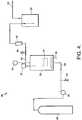
- FIG. 4depicts an example of apparatus 26 suitable for extracting the solvent from the water-depleted sol-gel 22' , using carbon dioxide.
- the sol-gel 22'is placed in a pressure vessel, or autoclave, 28 , which is provided with a heater 30 , a thermocouple 32 for measuring temperature, inlet means 34 for introducing a liquefiable gas, here, carbon dioxide, and outlet means 36 for removal of the gas.
- the gasis introduced to the autoclave 28 from a storage reservoir 38 and is compressed by a high pressure pump 40 .
- a pressure relief valve 42is provided in the inlet line 34 .
- Exiting of spent carbon dioxide from the autoclave 28is controlled by a flow control valve 44 in the outlet line 36 .
- a pressure gauge 46 before the flow control valve 44 and flow meter 48 after the flow control valveare provided for monitoring the pressure.
- a solvent trap 50collects the solvent removed from the pores of the sol-gel 22' , and the spent carbon dioxide is vented via vent 52 .
- the dried gelis heat-treated next in a conventional or a microwave furnace [step 8].
- a temperature range of 500° to 900°C for a period of 1 to 120 minutesis utilized to convert the ferroelectric aerogel from an amorphous to a crystalline microstructure.
- the sintering processis carefully controlled so the gel shrinkage is minimized and densification is not allowed to proceed to full density.
- Microwave sinteringcan be employed with potentially more accurate control of the sintering process.
- Conventional ovens and furnacesmay also be utilized for sintering ferroelectric aerogels.
- the effect of heat treatment temperature on the crystallinity of the aerogelcan be determined through the use of x-ray diffraction.
- the degree of crystallinitydepends upon the composition, time, and temperature as the principal variables. For example, heat treatments of 105° through 500°C yield amorphous BST; however, as the temperature approaches 600°C, a very pure single-phase BST is obtained.
- the results of x-ray diffraction studiesare shown for the heat-treated BST samples in Table II. Lower heat treatment temperatures (near 600°C) yield higher porosity and lower dielectric constant values.
- the last step in the processis to infiltrate the aerogel pores with a low dielectric loss polymer [step 9].
- a low dielectric loss polymermeans a dielectric loss of less than 3.
- Polystyreneis a low-loss polymer which may be employed for this purpose. Examples of other low-loss polymers include polyethylene, polypropylene, fluorinated poly(ethylene-co-propylene), polycarbonate, and polyphenylene oxide.
- the infiltration processmay be accomplished by first removing any surface moisture from the aerogel by evacuating with a mechanical vacuum pump, since the presence of any moisture will result in a greatly increased value of dielectric loss, which is detrimental for antenna applications. Gentle heating while evacuating the aerogel will speed up the process of moisture removal. Normally, a time period of 2 to 4 hours at 25°C can be reduced to one of 30 minutes to 1 hour by heating at 105°C.
- the aerogelis allowed to cool to 25 to 30°C and the impregnating monomer or mixture of monomers with suitable initiator is introduced while still maintaining vacuum.
- the vacuumis maintained for 30 to 120 minutes to ensure that all the pores are filled with the polymer.
- the pressureis then increased to 100 to 2,500 psi (6.90 to 172.4 bar) by introducing nitrogen, argon, or other inert gas to pressurize the vessel.
- the inert gasprovides a means for forcing the polymer into any pores not filled by the vacuum infiltration step alone.
- the impregnating mixtureis polymerized and cross-linked (in the case of difunctional monomer) by increasing the temperature to 40° to 80°C for a period of 1 to 10 days. Generally, the use of lower temperatures and longer curing times reduces the stresses imposed upon the aerogel structure.
- the objectiveis to achieve a cross-linked, hardened polymer without destroying the connectivity of the aerogel skeleton structure. It has been found that a temperature of 40°C and a curing time of 4 days yields a connected aerogel microstructure with no visible cracks using benzoyl peroxide as initiator. The curing time and temperature can be shortened from 4 to 2 days by using a different initiator such as t -butyl peroxodecanoate under atmospheric or elevated pressures at 50° to 80°C.
- the above-described processcan be varied to tailor the pore size, distribution, and pore volume.
- the dielectric propertiescan be engineered to meet a wide range of phase array radar applications.
Landscapes
- Chemical & Material Sciences (AREA)
- Engineering & Computer Science (AREA)
- Ceramic Engineering (AREA)
- Manufacturing & Machinery (AREA)
- Materials Engineering (AREA)
- Structural Engineering (AREA)
- Organic Chemistry (AREA)
- Dispersion Chemistry (AREA)
- Inorganic Chemistry (AREA)
- Inorganic Insulating Materials (AREA)
- Compositions Of Macromolecular Compounds (AREA)
- Details Of Aerials (AREA)
Abstract
Description
- The present invention relates to ferroelectric composites, and more particularly, to a method for preparing such composites employing sol-gels.
- The use of ferroelectric ceramics with voltage-tunable dielectric properties for electronically-scanned array (ESA) antenna applications has been severely limited due to a lack of suitable fabricated materials. The properties needed for these applications at high frequencies (about 10 to 80 Giga Hertz, GHz) include a low dielectric constant (less than about 100), a low loss tangent tan δ (less than about 0.010), a large electric field-induced change in refractive index (ranging from 0.25 to 1.2) with a maximum applied electric field of less than 50 kV/cm, and a high dielectric breakdown strength (about 80,000 to 100,000 V/cm).
- Composites have been under development with the idea of achieving a low-loss tangent by impregnating a porous structure with a low-loss polymer. These methods have involved the preparation of a ceramic powder, mixing it with a binder, burning out the binder to achieve a porous structure, sintering (firing), and then infiltrating the structure with a polymer. The difficulty with this conventional approach is that the homogeneity of the microstructure and resulting dielectric properties are not controllable within the desired limits of ±2%rms. Further, the polymer-impregnated ferroelectric composite exhibits loss at the operational frequencies, which is due, in part, to the presence of impurities introduced by conventional ceramic processing.
- Prior art approaches to provide materials with voltage-variable dielectric properties include two basic methods, neither of which is entirely satisfactory for the high-frequency ESA antennas. One method involves the use of porous ferroelectrics such as barium strontium titanate ((Ba,Sr)TiO₃; BST). The porous BST suffers from the separation of the individual particles with higher pore volumes and intrinsic difficulty in achieving a homogenous microstructure which controls the range of resulting dielectric properties. The separation of the individual particles is described as a lack of "connectivity", which is a term used to describe the degree of touching or connection between the particles. When the particles become more disconnected, then the applied field moves more into the polymer filler, which reduces the electric field-induced change in refractive index of the composite. The field must then be increased to obtain at least some electric field-induced change in refractive index, which leads to a dielectric breakdown or catastrophic arcing in the BST composite.
- The other method of achieving some electric field-induced change in refractive index is that of employing a honeycomb, or similarly structured, composite. The difficulty with this method is that the pores are relatively quite large, so that the effective range is limited to lower frequencies, less than about 5 GHz.
- Thus, a ferroelectric composite having a controlled, small-pore size is required, together with a process for making the same, for use at higher frequencies, on the order of 10 to 80 GHz.
- In accordance with the invention, a ferroelectric ceramic having a very uniform, small-pore size microstructure having a high porosity is provided. The pores of the ferroelectric ceramic are filled with an appropriate polymer to provide a novel ferroelectric composite. The minimum pore size within the composite depends upon the maximum operating frequency for the ESA antenna. The pores (and other scattering centers) in the ferroelectric aerogel composite should be small enough so that the diameterd of these centers is bounded by the following expression:

wherec is the speed of light, ν is the operating frequency and εc is the real part of the dielectric constant of the composite. The porosity of the ferroelectric aerogel can be as high as 98%, which exceeds the porosity of prior art materials by 20 to 30%. - The ferroelectric materials beneficially treated in accordance with the invention are the perovskites, which are characterized by the formula ABO₃. Well-known examples of such ferroelectric perovskites include BaTiO₃ and (Ba,-Sr)TiO₃.
- The ferroelectric composite of the present invention is provided by a sol-gel derived aerogel preparation process. The process comprises:
- (a) providing alcoholates of the respective metals employed in the ferroelectric material;
- (b) combining the metal alcoholates and subjecting them to an equilibration reaction to form an equilibrated metal alcoholate solution;
- (c) hydrolyzing and condensing the equilibrated solution product to form a gel having pores permeated with water and alcohol;
- (d) removing the water and alcohol from the pores to leave an aerogel foam;
- (e) heat-treating the aerogel foam; and
- (f) filling the pores with a suitable polymer to form the ferroelectric composite.
- The final product, comprising a porous ferroelectric material whose pores are filled with a low (<3) dielectric constant polymer, is characterized by a pore size depending on the maximum operational frequency of the ESA antenna and the real part of the dielectric constant of the material, as set forth in Eqn. (1), above. If the operational frequency is 94 GHz and the dielectric constant is 30, then the pore size can be no greater than 30 µm. The maximum pore size distribution should be less than 30 µm. The porosity depends on the dielectric constant and loss tangent sought for the polymer-infiltrated aerogel composite. High/low porosity yields low/high values for the dielectric constant and loss tangent. As a rule, the porosity should be greater than 80% for aerogel composites made from ferroelectric perovskites.
- The present invention overcomes the difficulties associated with the prior art through the use of the sol-gel derived aerogel preparation process. Fabrication of the ferroelectric ceramic using the aerogel route permits preparation of a very uniform, small-pore size microstructure material which can be formed into the desired shape. The process eliminates many conventional ceramic processing steps which introduce impurities, such as milling, grinding, binder addition, mixing, screening, and pressing. The sol-gel process for fabricating aerogels permits fabrication of an ultra-pure finished product. The high purity together with the very small pore size provides a means of achieving low loss at high frequencies.
- The ferroelectric aerogel composite of the present invention overcomes the lack of interconnectivity associated with prior art structures at porosities greater than 70 to 80% with a fully connected aerogel structure.
- The homogeneity problem of prior art porous BST is eliminated by the very uniform micro-pore aerogels. The aerogel process of the present invention prevents impurities from entering the micro-structure.
- The ferroelectric aerogel composite micropores minimize the scattering of microwave and millimeter-wave radiation to allow its use at frequencies of interest (10 to 80 GHz), beyond the range of the honeycomb composites.
- FIG. 1 is a photomicrograph depicting the microstructure of a typical BST aerogel heat-treated for 1 hour at 500°C and then impregnated with polystyrene (SEM photograph taken at 10,000X magnification);
- FIG. 2 is a flow chart for the fabrication of ferroelectric aerogel composites in accordance with the invention;
- FIG. 3 is a side elevational view of vacuum extraction apparatus useful in the practice of the present invention; and
- FIG. 4 is a schematic diagram of carbon dioxide extraction apparatus useful in the practice of the present invention.
- The ferroelectric aerogel composite of the present invention provides a means for the intrinsic non-linear characteristics of some ferroelectric ceramics to be exploited for microwave antennas and other applications. An analysis of the dielectric properties of the ferroelectric aerogel composite will be given first, followed by a description of their fabrication by the methods of the present invention.
- The description which follows is presented in terms of a specific perovskite ferroelectric material, (Ba,Sr)TiO₃. However, it will be readily appreciated that other ferroelectric oxide materials, such as titanates, zirconates, tantalates, and niobates, may also be treated by the process of the invention to provide a novel ferroelectric composite.
- The important dielectric properties of a two-phase ferroelectric aerogel composite are (1) the real permittivity, or real part of the dielectric constant, εc; (2) the loss tangent, tan δ; (3) the fractional tunability Tc; (4) the scan figure-of-merit, SFMc; and (5) the loss or attenuation αc. The equations defining these properties are described below.
- The permittivity of a two-phase ferroelectric aerogel composite can be estimated by the logarithmic law of mixing derived by Lichtenecker and Rother:

where Xf and εf are the volume fraction and permittivity of the ferroelectric phase, and εp is the permittivity of a polymer-filler phase. - Eqn. (2) can be rewritten as

- It will be noted that Eqns. (2) and (3) are rigorously applicable to a random mixture having spherical - or near-spherical-shaped inclusions.
- The loss tangent of a two-phase ferroelectric aerogel composite can be estimated by an arithmetic law of mixing:

where tan δf and tan δp are the loss tangents for the ferroelectric and polymer filler phases, respectively. - The fractional tunability for a two-phase ferroelectric aerogel composite is defined as:

where |Δεc| is the change in permittivity from zero voltage bias to maximum applied dc bias. Based on Eqn. (3), this term can be expressed as:
where Tf and Tp are the fractional tunabilities for the ferroelectric and polymer phases, respectively. It will be noted that it is assumed here that the applied dc bias reduces εf and εp. - The scan figure of merit, SFMc, for a two-phase ferroelectric aerogel composite is the electric field-induced change in refractive index and is defined as:

- The loss or attenuation of an electromagnetic field propagating in a two-phase ferroelectric aerogel composite is given by:

where λ(cm) is the wavelength of the electromagnetic wave in a vacuum. - Consider a two-phase ferroelectric aerogel composite consisting of the ferroelectric ceramic, barium strontium titanate (Ba0.6Sr0.4TiO₃), and the polymer filler, polystyrene. The salient dielectric properties measured at 3 GHz and 26°C for the pure-barium strontium titanate phase are εf = 2650, tan δ = 0.15 and Tf = 0.56 for a 28,000 V/cm bias field, as reported by K.M. Johnson,Journal of Applied Physics, Vol. 33, Pp. 2826-2831, (1962). The important dielectric properties measured at 3 GHz and 25°C for the polystyrene phase are εp = 2.5, tan δp = 0.002, and Tp ∼0.0, as reported inElectronics Designer's Handbook, L.J. Giacoletto, Ed., McGraw-Hill, New York, pg. 2-64, (1977).
- The dielectric properties of the composite calculated as a function of Xf are listed in Table I.


- The salient conclusion that can be drawn from the calculated results presented in Table I is that a ferroelectric aerogel composite with a reasonable ferroelectric volume fraction of about 0.2 to 0.3 is predicted to have a permittivity in the desired range of about 10 to 20, a scan figure of merit in the desired range of about 0.25 to 0.52, and a loss ranging from 0.68 to 1.42 dB/inch (0.27 to 0.56 dB/cm) at 3 GHz.
- The predicted properties in the Table are within the requirements for ESA antenna applications at microwave frequencies.
- The inclusions in the ferroelectric aerogel composite should be small enough so that the electromagnetic wave at the frequency or wavelength of interest is not scattered by these inclusions. According to the theory of the scattering of electromagnetic radiation, an upper bound on the sized of the inclusions is given by the following expression:

wherec is the speed of light and ν is the frequency. Thus, for ν = 94 GHz and εc = 30, the inclusion size can be no greater than about 6 µm. This upper bound increases with decreasing frequency. Submicrometer pore sizes and inclusions can be easily achieved using the aerogel approach to fabricating ferroelectric composites. - A ferroelectric aerogel is connected almost by definition. In contrast to the conventional approaches to the fabrication of porous ceramics, the aerogel approach establishes connectivity at the atomic and/or molecular level through solution-gelation chemistry.
- The microstructure in FIG. 1 illustrates the skeletal aerogel connectivity. Specifically, FIG. 1 shows the aerogel impregnated with polystyrene.
- The ferroelectric aerogel composite of the present invention can be fabricated using an aerogel preparation process shown in the flow chart in FIG. 2. Preparation of aerogels in the past has been limited largely to silica, alumina, and zirconia.
- It will be noted that the process avoids the contaminating activities of crushing, grinding, and screening of conventional ceramic processing. The process of the present invention broadly comprises:
- (a) providing alcoholates of the respective metals employed in the ferroelectric material;
- (b) combining the metal alcoholates and subjecting them to an equilibration reaction to form an equilibrated metal alcoholate solution;
- (c) hydrolyzing and condensing the equilibrated solution of step (b) by addition of water;
- (d) removing the water and alcohol from the pores to leave an aerogel foam;
- (e) heat-treating the aerogel foam; and
- (f) filling the pores with a suitable polymer to form the ferroelectric composite.
- In the case of preparing (Ba,Sr)TiO₃, an alcoholate solution of the metals in the desired proportions is provided. For titanium, a commercial form of titanium isopropoxide is available, and may be employed in the practice of the invention. For barium and strontium, the alcoholate solution is prepared by dissolving barium and strontium metals in 2-methoxyethanol [step 1]. The titanium alcoholate is added to the barium/strontium alcoholate solution [step 2]. The reactants are subjected to an equilibration, such as refluxing for several hours, e.g., 2 to 8 hours, in a reactor at 135°C under nitrogen to form an equilibrated solution of the metal alcoholates [step 3]. The equilibrated solution is poured into a mold which has the shape of the desired final composite and a stoichiometric or greater amount of water is added [step 4]. The amount of water is based on the concentration of the metal ions. The water must be diluted by adding one part 2-methoxyethanol to three parts water (by volume) prior to addition to the equilibrated solution to assure uniform gelation. The mold must be sealed with an air-tight lid to prevent evaporation of the solvent during curing. Gels may be cured slowly (1 to 10 days) at room temperature or quickly at elevated temperature (1 to 60 min at 60°C). Larger additions of water also accelerate gel times.
- The gel is then treated, first to remove excess water, and then to remove the solvent. The treatment must be carried out in such a manner that the capillary forces from the solvent and water are not allowed to collapse the porous structure.
- The water in the gel is extracted by immersing the mold in a large excess of anhydrous solvent [step 5]. The volume of solvent must be large enough to reduce the residual water content of the gel to less than 0.1% by weight. The solvent may be an alcohol or other organic solvent which is miscible with water and is also readily soluble in liquid carbon dioxide. Examples of such solvents include methanol, ethanol, 2-methoxyethanol, and acetone. Acetone is preferred, since it has a low solubility for partially hydrolyzed alcoholates. Alternately, the mold can be placed in a smaller amount of the solvent to which sufficient desiccant has been added to absorb the water. The time required for water extraction depends on the thickness of the gel. Thin samples on the order of 1 millimeter may be exchanged in a few hours. Thicker samples on the order of a few centimeters may be exchanged in a few days. Faster extraction times may be achieved if the mold can be designed such that vacuum filtration can be used to draw solvent through the gel and flush out residual water.
- FIG. 3 depicts an example of
apparatus 10 suitably employed in the water-extraction step. Theapparatus 10 comprises avacuum filtration flask 12 provided with anopening 14 and anoutlet 16. Theopening 14 is sealed against the atmosphere with arubber stopper 18, in which afilter funnel 20 is placed, containing the cured sol-gel 22. Anhydrous solvent24 is contained in the top of thefilter funnel 20. Theoutlet 16 is connected to a source of vacuum (not shown), such as a vacuum pump. Forming a vacuum in thefiltration flask 12 draws the anhydrous solvent24 through the sol-gel 22, displacing water in its pores. The water, which is removed from the sol-gel 22 until there is less than 0.1% by weight in the sol-gel, is collected in thefiltration flask 12. - Next, the solvent in the gel is removed by placing the mold in an autoclave and pressurizing with liquid carbon dioxide at about 15° to 30°C at pressures of 700 to 1,000 pounds per square inch (psi) (48.3 to 68.9 bar) [step 6]. For a liquified compressed gas other than carbon dioxide, the temperature is about 1 to 16°C below its critical temperature and the pressure is about 70 to 370 psi (4.8 to 25.5 bar) below its critical pressure.
- The solvent then diffuses out of the gel as liquid carbon dioxide diffuses in. A slow flow of fresh carbon dioxide into the autoclave is maintained in order to flush out the extracted solvent. The total volume of carbon dioxide must be sufficient to reduce the residual solvent content to less than 0.1%. As with the water extraction process, the immersion and flow time depend on the thickness of the sample. Thin samples may be extracted in a few hours; thicker samples may take a few days.
- The gel is then dried by heating the autoclave above the critical point of carbon dioxide, 31°C at 1,070 psi (73.8 bar), to a temperature of 40° to 60°C for about 1 hour [step 7]. As a result of heating, the pressure rises to a range of about 1,400 to 2,000 psi (96.6 to 137.9 bar).
- For a liquified compressed gas other than carbon dioxide, the temperature is about 9 to 29°C above its critical temperature and the pressure generated is about 330 to 930 psi (22.8 to 64.1 bar) above its critical pressure.
- During the transformation of liquid to supercritical fluid, the surface tension of the fluid in the pores of the gel is reduced to zero, thus removing stresses induced by capillary forces. After the supercritical state is reached, the pressure may be slowly released at constant temperature over a period of about 1 hour, converting the supercritical fluid into gas, thus yielding a solvent-free aerogel.
- Carbon dioxide is preferred, since it exhibits a critical temperature much lower than alcohols (31°C vs. 255°C) and is non-flammable and non-toxic. Other liquified compressed gases with convenient critical points may be used, provided that the temperatures and pressures are adjusted accordingly. Examples of such fluids include nitrous oxide, sulfur hexafluoride, and trifluoromethane. The dried gel at this stage is exceedingly fragile and must be handled with care.
- FIG. 4 depicts an example of
apparatus 26 suitable for extracting the solvent from the water-depleted sol-gel22', using carbon dioxide. The sol-gel22' is placed in a pressure vessel, or autoclave,28, which is provided with aheater 30, athermocouple 32 for measuring temperature, inlet means34 for introducing a liquefiable gas, here, carbon dioxide, and outlet means36 for removal of the gas. - The gas is introduced to the
autoclave 28 from astorage reservoir 38 and is compressed by ahigh pressure pump 40. Apressure relief valve 42 is provided in theinlet line 34. - Exiting of spent carbon dioxide from the
autoclave 28 is controlled by aflow control valve 44 in theoutlet line 36. Apressure gauge 46 before theflow control valve 44 and flowmeter 48 after the flow control valve are provided for monitoring the pressure. Asolvent trap 50 collects the solvent removed from the pores of the sol-gel22', and the spent carbon dioxide is vented viavent 52. - The dried gel is heat-treated next in a conventional or a microwave furnace [step 8]. A temperature range of 500° to 900°C for a period of 1 to 120 minutes is utilized to convert the ferroelectric aerogel from an amorphous to a crystalline microstructure. The sintering process is carefully controlled so the gel shrinkage is minimized and densification is not allowed to proceed to full density. Microwave sintering can be employed with potentially more accurate control of the sintering process. Conventional ovens and furnaces may also be utilized for sintering ferroelectric aerogels.
- The effect of heat treatment temperature on the crystallinity of the aerogel can be determined through the use of x-ray diffraction. The degree of crystallinity depends upon the composition, time, and temperature as the principal variables. For example, heat treatments of 105° through 500°C yield amorphous BST; however, as the temperature approaches 600°C, a very pure single-phase BST is obtained. The results of x-ray diffraction studies are shown for the heat-treated BST samples in Table II. Lower heat treatment temperatures (near 600°C) yield higher porosity and lower dielectric constant values.


- The last step in the process is to infiltrate the aerogel pores with a low dielectric loss polymer [step 9]. As used herein, the term "low dielectric loss" means a dielectric loss of less than 3. Polystyrene is a low-loss polymer which may be employed for this purpose. Examples of other low-loss polymers include polyethylene, polypropylene, fluorinated poly(ethylene-co-propylene), polycarbonate, and polyphenylene oxide.
- The infiltration process may be accomplished by first removing any surface moisture from the aerogel by evacuating with a mechanical vacuum pump, since the presence of any moisture will result in a greatly increased value of dielectric loss, which is detrimental for antenna applications. Gentle heating while evacuating the aerogel will speed up the process of moisture removal. Normally, a time period of 2 to 4 hours at 25°C can be reduced to one of 30 minutes to 1 hour by heating at 105°C.
- Next, the aerogel is allowed to cool to 25 to 30°C and the impregnating monomer or mixture of monomers with suitable initiator is introduced while still maintaining vacuum. The vacuum is maintained for 30 to 120 minutes to ensure that all the pores are filled with the polymer. The pressure is then increased to 100 to 2,500 psi (6.90 to 172.4 bar) by introducing nitrogen, argon, or other inert gas to pressurize the vessel. The inert gas provides a means for forcing the polymer into any pores not filled by the vacuum infiltration step alone. The impregnating mixture is polymerized and cross-linked (in the case of difunctional monomer) by increasing the temperature to 40° to 80°C for a period of 1 to 10 days. Generally, the use of lower temperatures and longer curing times reduces the stresses imposed upon the aerogel structure.
- The objective is to achieve a cross-linked, hardened polymer without destroying the connectivity of the aerogel skeleton structure. It has been found that a temperature of 40°C and a curing time of 4 days yields a connected aerogel microstructure with no visible cracks using benzoyl peroxide as initiator. The curing time and temperature can be shortened from 4 to 2 days by using a different initiator such ast-butyl peroxodecanoate under atmospheric or elevated pressures at 50° to 80°C.
- The above-described process can be varied to tailor the pore size, distribution, and pore volume. In this way, together with the infinite flexibility of the aerogel process with regard to ferroelectric compositions, the dielectric properties can be engineered to meet a wide range of phase array radar applications.
- Thus, there has been disclosed ferroelectric aerogel composites for voltage-variable dielectric tuning and a method for making the same. It will be readily apparent to those skilled in this art that various changes and modifications of an obvious nature may be made, and all such changes and modifications are considered to fall within the scope of the invention, as defined by the appended claims.


Claims (8)
- A process for preparing a ferroelectric composite comprising a sol-gel of a ferroelectric material comprising an oxide of at least two metals, said ferroelectric composite impregnated with a polymer, comprising:(a) providing alcoholates of said at least two metals to form metal alcoholates;(b) combining said metal alcoholates and subjecting them to an equilibration reaction to form an equilibrated metal alcoholate solution;(b) hydrolyzing and condensing said equilibrated metal alcoholate solution by addition of water to form a gel having pores permeated with water and alcohol;(d) removing said water and alcohol from said pores of said gel to leave an aerogel foam;(e) heat-treating said aerogel foam; and(f) filling said pores with said polymer to form said ferroelectric composite, said polymer having a dielectric constant of less than 3.
- The process of claim 1 wherein said ferroelectric material comprises a crystalline oxide having a perovskite structure.
- The process of claim 2 wherein said ferroelectric material comprises a perovskite selected from the group consisting of BaTiO₃, SrTiO₃, and (Ba, Sr)TiO₃.
- The process of any of claims 1 to 4 wherein said water and alcohol are removed from said pores by a process comprising:(a) extracting said water by immersing said gel in a volume of solvent sufficient to reduce the residual water content to less than 0.1 % weight, in which said solvent is miscible with water and soluble in liquified compressed gas;(b) extracting said solvent by autoclaving in a volume of liquified compressed gas sufficient to reduce the residual content of said solvent to less than 0.1 % by weight with said liquified compressed gas at a temperature of 1° to 16°C below its critical temperature and at a pressure of 70 to 370 pounds per square inch (4.8 to 25.5 bar) below its critical pressure;(c) heating said liquified compressed gas to a temperature 9 to 29°C above its critical point, thus generating supercritical fluid at a pressure of about 330 to 930 pounds per square inch (22.8 to 64.1 bar) above its critical pressure for about 1 hour; and(d) depressurizing said supercritical fluid at constant temperature to atmospheric pressure over a period of at least 1 hour, thus converting said supercritical fluid into gas, and thereby providing said aerogel foam.
- The process of any of claims 1 to 4 wherein said crystallinity is induced in said aerogel foam by sintering at a temperature ranging from about 500° to 900°C for a period of time ranging from 1 to 120 minutes.
- The process of any of claims 1 to 5 wherein said pores are filled with said polymer by vacuum impregnation.
- The process of claim 6 wherein following said vacuum impregnation, said aerogel is subjected to an inert gas under a pressure ranging from about 100 to 2,500 pounds per square inch (6.9 to 172.4 bar).
- A ferroelectric composite comprising a non-linear ferroelectric material having a pore size d filled with a polymer having a dielectric constant of less than 3, said composite intended for device applications at an operating frequencyand having a composite dielectric constant comprising a real part and an imaginary part, said pore size given by:

 is said operating frequency and εc is said real part of said composite dielectric constant, said composite having a porosity of at least about 80 %.


Applications Claiming Priority (2)
| Application Number | Priority Date | Filing Date | Title |
|---|---|---|---|
| US08/195,111US5443746A (en) | 1994-02-14 | 1994-02-14 | Ferroelectric aerogel composites for voltage-variable dielectric tuning, and method for making the same |
| US195111 | 1994-02-14 |
Publications (2)
| Publication Number | Publication Date |
|---|---|
| EP0667324A1true EP0667324A1 (en) | 1995-08-16 |
| EP0667324B1 EP0667324B1 (en) | 1999-04-07 |
Family
ID=22720092
Family Applications (1)
| Application Number | Title | Priority Date | Filing Date |
|---|---|---|---|
| EP95101957AExpired - LifetimeEP0667324B1 (en) | 1994-02-14 | 1995-02-14 | Ferroelectric aerogel composites for voltage-variable dielectric tuning, and method for making the same |
Country Status (4)
| Country | Link |
|---|---|
| US (1) | US5443746A (en) |
| EP (1) | EP0667324B1 (en) |
| JP (1) | JP2581906B2 (en) |
| DE (1) | DE69508823T2 (en) |
Cited By (3)
| Publication number | Priority date | Publication date | Assignee | Title |
|---|---|---|---|---|
| EP0826649A1 (en)* | 1996-08-29 | 1998-03-04 | HE HOLDINGS, INC. dba HUGHES ELECTRONICS | Methods of making ferroelectric ceramic-polymer composites for voltage-variable dielectric tuning and structures using same |
| EP0875905A1 (en)* | 1997-04-28 | 1998-11-04 | STMicroelectronics S.r.l. | Low dielectric constant composite film for integrated circuits of an inorganic aerogel and an organic filler grafted to the inorganic material and method of fabrication |
| WO2017121204A1 (en)* | 2016-01-11 | 2017-07-20 | 苏州大学张家港工业技术研究院 | Modified barium titanate foam ceramic/thermosetting resin composite material and preparation method therefor |
Families Citing this family (20)
| Publication number | Priority date | Publication date | Assignee | Title |
|---|---|---|---|---|
| US5470802A (en)* | 1994-05-20 | 1995-11-28 | Texas Instruments Incorporated | Method of making a semiconductor device using a low dielectric constant material |
| KR100406665B1 (en)* | 1995-06-09 | 2004-03-26 | 미쓰비시 마테리알 가부시키가이샤 | Compositions for forming Ba1-xSrxTiyO3 thin films and methods for forming Ba1-xSrxTiyO3 thin films |
| US5525162A (en)* | 1995-06-26 | 1996-06-11 | The United States Of America As Represented By The Secretary Of The Army | Thermal conductivity enhancement technique |
| US5635433A (en)* | 1995-09-11 | 1997-06-03 | The United States Of America As Represented By The Secretary Of The Army | Ceramic ferroelectric composite material-BSTO-ZnO |
| US5766697A (en)* | 1995-12-08 | 1998-06-16 | The United States Of America As Represented By The Secretary Of The Army | Method of making ferrolectric thin film composites |
| DE19622500C2 (en)* | 1996-06-05 | 1998-09-17 | Fraunhofer Ges Forschung | Process for the production of porous ceramics with the composition Pb (Zr¶x¶Ti¶1¶-¶x¶) 0¶3¶ |
| US6037046A (en)* | 1997-01-13 | 2000-03-14 | Symetrix Corporation | Multi-component electromagnetic wave absorption panels |
| AU2001268428A1 (en) | 2000-06-16 | 2002-01-02 | Paratek Microwave, Inc. | Electronically tunable dielectric composite thick films |
| US7270851B2 (en)* | 2004-11-04 | 2007-09-18 | The United States Of America As Represented By The Administrator Of The National Aeronautics And Space Administration | Method for nanoencapsulation of aerogels and nanoencapsulated aerogels produced by such method |
| US7741396B2 (en)* | 2005-11-23 | 2010-06-22 | General Electric Company | Composites having tunable dielectric constants, methods of manufacture thereof, and articles comprising the same |
| GB0803129D0 (en)* | 2008-02-21 | 2008-03-26 | Univ Manchester | insulating medium and its use in high voltage devices |
| US8007989B1 (en) | 2008-04-11 | 2011-08-30 | The United States Of America As Represented By The Secretary Of The Navy | Method and solution for forming a patterned ferroelectric layer on a substrate |
| US20110129614A1 (en)* | 2009-12-01 | 2011-06-02 | Lawrence Livermore National Security, Llc | Extreme synthesis of crystalline aerogel materials from amorphous aerogel precursors |
| US9018060B2 (en)* | 2010-06-15 | 2015-04-28 | 3M Innovative Properties Company | Variable capacitance sensors and methods of making the same |
| JP5857341B2 (en)* | 2011-07-29 | 2016-02-10 | 株式会社ユーテック | Method for manufacturing ferroelectric film |
| WO2017075554A1 (en) | 2015-10-29 | 2017-05-04 | Golfetto Michael | Methods freeze drying and composite materials |
| CN108714419A (en)* | 2018-04-25 | 2018-10-30 | 南京工业大学 | SrTiO for photocatalysis3Method for producing aerogel powder |
| CN108545771B (en)* | 2018-07-03 | 2020-06-16 | 电子科技大学 | A kind of preparation method of barium strontium titanate aerogel |
| RU2706275C1 (en)* | 2018-12-21 | 2019-11-15 | федеральное государственное бюджетное образовательное учреждение высшего образования "Московский политехнический университет" (Московский Политех) | Method of producing barium titanate-based ceramics |
| EP4007006B1 (en) | 2019-07-29 | 2023-09-06 | Hefei Gotion High-Tech Power Energy Co., Ltd. | Thermal insulation composition and preparation method and application |
Citations (2)
| Publication number | Priority date | Publication date | Assignee | Title |
|---|---|---|---|---|
| EP0208019A2 (en)* | 1985-06-07 | 1987-01-14 | Celanese Corporation | Piezoelectric-polymer 0-3 composites for transducer applications |
| JPH06119811A (en)* | 1992-10-06 | 1994-04-28 | Seiko Epson Corp | Method for manufacturing ferroelectric thin film element |
Family Cites Families (5)
| Publication number | Priority date | Publication date | Assignee | Title |
|---|---|---|---|---|
| JPS53110133A (en)* | 1977-03-07 | 1978-09-26 | Tdk Electronics Co Ltd | Porcelain heating element made from positive characteristic semiconductor |
| DE2905905A1 (en)* | 1978-02-22 | 1979-08-23 | Tdk Electronics Co Ltd | COMB-SHAPED HEATING ELEMENT |
| SU912714A1 (en)* | 1980-01-11 | 1982-03-15 | Предприятие П/Я В-8941 | Method for producing piezoelectric ceramic material |
| US4726099A (en)* | 1986-09-17 | 1988-02-23 | American Cyanamid Company | Method of making piezoelectric composites |
| FR2665699A1 (en)* | 1990-08-07 | 1992-02-14 | Thomson Csf | PIEZOELECTRIC CERAMIC WITH CONTROLLED POROSITY. |
- 1994
- 1994-02-14USUS08/195,111patent/US5443746A/ennot_activeExpired - Fee Related
- 1995
- 1995-02-14JPJP7025661Apatent/JP2581906B2/ennot_activeExpired - Fee Related
- 1995-02-14EPEP95101957Apatent/EP0667324B1/ennot_activeExpired - Lifetime
- 1995-02-14DEDE69508823Tpatent/DE69508823T2/ennot_activeExpired - Fee Related
Patent Citations (2)
| Publication number | Priority date | Publication date | Assignee | Title |
|---|---|---|---|---|
| EP0208019A2 (en)* | 1985-06-07 | 1987-01-14 | Celanese Corporation | Piezoelectric-polymer 0-3 composites for transducer applications |
| JPH06119811A (en)* | 1992-10-06 | 1994-04-28 | Seiko Epson Corp | Method for manufacturing ferroelectric thin film element |
Non-Patent Citations (1)
| Title |
|---|
| DATABASE WPI Week 9422, Derwent World Patents Index; AN 94-179250* |
Cited By (5)
| Publication number | Priority date | Publication date | Assignee | Title |
|---|---|---|---|---|
| EP0826649A1 (en)* | 1996-08-29 | 1998-03-04 | HE HOLDINGS, INC. dba HUGHES ELECTRONICS | Methods of making ferroelectric ceramic-polymer composites for voltage-variable dielectric tuning and structures using same |
| EP0875905A1 (en)* | 1997-04-28 | 1998-11-04 | STMicroelectronics S.r.l. | Low dielectric constant composite film for integrated circuits of an inorganic aerogel and an organic filler grafted to the inorganic material and method of fabrication |
| US6087729A (en)* | 1997-04-28 | 2000-07-11 | Sgs-Thomson Microelectronics S.R.L. | Low dielectric constant composite film for integrated circuits of an inorganic aerogel and an organic filler grafted to the inorganic material |
| WO2017121204A1 (en)* | 2016-01-11 | 2017-07-20 | 苏州大学张家港工业技术研究院 | Modified barium titanate foam ceramic/thermosetting resin composite material and preparation method therefor |
| US10807916B2 (en) | 2016-01-11 | 2020-10-20 | Soochow University | Modified barium titanate foam ceramic/thermosetting resin composites and preparation method thereof |
Also Published As
| Publication number | Publication date |
|---|---|
| EP0667324B1 (en) | 1999-04-07 |
| JPH083464A (en) | 1996-01-09 |
| DE69508823D1 (en) | 1999-05-12 |
| US5443746A (en) | 1995-08-22 |
| DE69508823T2 (en) | 1999-08-19 |
| JP2581906B2 (en) | 1997-02-19 |
Similar Documents
| Publication | Publication Date | Title |
|---|---|---|
| EP0667324B1 (en) | Ferroelectric aerogel composites for voltage-variable dielectric tuning, and method for making the same | |
| Tewari et al. | Ambient-temperature supercritical drying of transparent silica aerogels | |
| Mulder et al. | Preparation, densification and characterization of autoclave dried SiO2 gels | |
| US9556321B2 (en) | High dielectric constant composite materials and methods of manufacture | |
| EP0826649B1 (en) | Methods of making ferroelectric ceramic-polymer composites for voltage-variable dielectric tuning and structures using same | |
| Wang et al. | The role of excess magnesium oxide or lead oxide in determining the microstructure and properties of lead magnesium niobate | |
| Liou et al. | Dielectric tunability of barium strontium titanate/silicone-rubber composite | |
| Zhang et al. | Dielectric behaviour of nano‐TiO2 bulks | |
| Kawakami et al. | Preparation of highly porous silica aerogel thin film by supercritical drying | |
| Cho | Sintering behavior and dielectric properties of A3 (PO4) 2 compounds (A= Ca, Sr, Ba, Mg, Zn, Ni, Cu) | |
| KR20210122225A (en) | Doped perovskite barium stannate material and manufacturing method and application thereof | |
| Luo et al. | Polytetrafluoroethylene based, F8261 modified realization of Li2SnMg0. 5O3. 5 filled composites | |
| Duffours et al. | Irreversible volume shrinkage of silica aerogels under isostatic pressure | |
| Schaefer et al. | Structure and topology of silica aerogels | |
| CA1315961C (en) | Methods of producing microwave devices | |
| Lours et al. | SAXS and BET studies of aging and densification of silica aerogels | |
| Yasuda et al. | Dielectric properties of Pb (Fe2/3W1/3) O3 under pressure | |
| Constant et al. | Microstructure development in furfuryl resin-derived microporous glassy carbons | |
| Kazaoui et al. | Dielectric relaxation in Ba (Ti0. 8Zr0. 2) O3 ceramics prepared from sol-gel and solid state reaction powders | |
| Cross et al. | Ultra-Low Dielectric Permitfivity Ceramics and Composites for Packaging Applications | |
| Yeo et al. | Dielectric Properties of (1-x) CaTiO3–xLa (Zn1/2Ti1/2) O3 Ceramics at Microwave Frequencies | |
| Naito et al. | Pore size distribution during compaction and early stage sintering of silicon nitride | |
| Villegas et al. | Processing and properties of Pb (Mg1/3Nb2/3) O3-PbZrO3-PbTiO3 ceramic relaxors | |
| Solomon et al. | Microwave dielectric resonators based on Ba [(Bi0. 2D0. 33+) Nb0. 5] O3 (D3+= Y, Pr, Sm, Gd, Dy, Er) | |
| Fountzoulas | Microstructural Development and Properties of (1-x) wt% Ba0. 55Sr0. 45TiO3-x wt% MgO Bulk Ferroelectrics |
Legal Events
| Date | Code | Title | Description |
|---|---|---|---|
| PUAI | Public reference made under article 153(3) epc to a published international application that has entered the european phase | Free format text:ORIGINAL CODE: 0009012 | |
| AK | Designated contracting states | Kind code of ref document:A1 Designated state(s):DE FR GB IT SE | |
| RIN1 | Information on inventor provided before grant (corrected) | Inventor name:DOUGHERTY, THOMAS K. Inventor name:TOWNSEND, CARL W. Inventor name:PIERCE, BRIAN M. Inventor name:HARRIS, NORMAN H. | |
| 17P | Request for examination filed | Effective date:19960105 | |
| 17Q | First examination report despatched | Effective date:19960719 | |
| GRAG | Despatch of communication of intention to grant | Free format text:ORIGINAL CODE: EPIDOS AGRA | |
| GRAG | Despatch of communication of intention to grant | Free format text:ORIGINAL CODE: EPIDOS AGRA | |
| GRAH | Despatch of communication of intention to grant a patent | Free format text:ORIGINAL CODE: EPIDOS IGRA | |
| GRAH | Despatch of communication of intention to grant a patent | Free format text:ORIGINAL CODE: EPIDOS IGRA | |
| RAP1 | Party data changed (applicant data changed or rights of an application transferred) | Owner name:RAYTHEON COMPANY | |
| GRAA | (expected) grant | Free format text:ORIGINAL CODE: 0009210 | |
| AK | Designated contracting states | Kind code of ref document:B1 Designated state(s):DE FR GB IT SE | |
| ITF | It: translation for a ep patent filed | ||
| REF | Corresponds to: | Ref document number:69508823 Country of ref document:DE Date of ref document:19990512 | |
| ET | Fr: translation filed | ||
| PLBE | No opposition filed within time limit | Free format text:ORIGINAL CODE: 0009261 | |
| STAA | Information on the status of an ep patent application or granted ep patent | Free format text:STATUS: NO OPPOSITION FILED WITHIN TIME LIMIT | |
| 26N | No opposition filed | ||
| REG | Reference to a national code | Ref country code:GB Ref legal event code:IF02 | |
| PG25 | Lapsed in a contracting state [announced via postgrant information from national office to epo] | Ref country code:IT Free format text:LAPSE BECAUSE OF NON-PAYMENT OF DUE FEES;WARNING: LAPSES OF ITALIAN PATENTS WITH EFFECTIVE DATE BEFORE 2007 MAY HAVE OCCURRED AT ANY TIME BEFORE 2007. THE CORRECT EFFECTIVE DATE MAY BE DIFFERENT FROM THE ONE RECORDED. Effective date:20050214 | |
| PGFP | Annual fee paid to national office [announced via postgrant information from national office to epo] | Ref country code:FR Payment date:20060112 Year of fee payment:12 | |
| PGFP | Annual fee paid to national office [announced via postgrant information from national office to epo] | Ref country code:GB Payment date:20060116 Year of fee payment:12 | |
| PGFP | Annual fee paid to national office [announced via postgrant information from national office to epo] | Ref country code:DE Payment date:20060117 Year of fee payment:12 | |
| PGFP | Annual fee paid to national office [announced via postgrant information from national office to epo] | Ref country code:SE Payment date:20060120 Year of fee payment:12 | |
| PG25 | Lapsed in a contracting state [announced via postgrant information from national office to epo] | Ref country code:SE Free format text:LAPSE BECAUSE OF NON-PAYMENT OF DUE FEES Effective date:20070215 | |
| EUG | Se: european patent has lapsed | ||
| GBPC | Gb: european patent ceased through non-payment of renewal fee | Effective date:20070214 | |
| REG | Reference to a national code | Ref country code:FR Ref legal event code:ST Effective date:20071030 | |
| PG25 | Lapsed in a contracting state [announced via postgrant information from national office to epo] | Ref country code:DE Free format text:LAPSE BECAUSE OF NON-PAYMENT OF DUE FEES Effective date:20070901 | |
| PG25 | Lapsed in a contracting state [announced via postgrant information from national office to epo] | Ref country code:GB Free format text:LAPSE BECAUSE OF NON-PAYMENT OF DUE FEES Effective date:20070214 Ref country code:FR Free format text:LAPSE BECAUSE OF NON-PAYMENT OF DUE FEES Effective date:20070228 | |
| PGFP | Annual fee paid to national office [announced via postgrant information from national office to epo] | Ref country code:IT Payment date:20060228 Year of fee payment:12 | |
| PGRI | Patent reinstated in contracting state [announced from national office to epo] | Ref country code:IT Effective date:20080301 | |
| PGRI | Patent reinstated in contracting state [announced from national office to epo] | Ref country code:IT Effective date:20080301 |