EP0666021B1 - Metal detection apparatus for an agricultural harvester - Google Patents
Metal detection apparatus for an agricultural harvesterDownload PDFInfo
- Publication number
- EP0666021B1 EP0666021B1EP95200209AEP95200209AEP0666021B1EP 0666021 B1EP0666021 B1EP 0666021B1EP 95200209 AEP95200209 AEP 95200209AEP 95200209 AEP95200209 AEP 95200209AEP 0666021 B1EP0666021 B1EP 0666021B1
- Authority
- EP
- European Patent Office
- Prior art keywords
- magnets
- crop
- sensing element
- magnet
- feed
- Prior art date
- Legal status (The legal status is an assumption and is not a legal conclusion. Google has not performed a legal analysis and makes no representation as to the accuracy of the status listed.)
- Expired - Lifetime
Links
Images

Classifications
- A—HUMAN NECESSITIES
- A01—AGRICULTURE; FORESTRY; ANIMAL HUSBANDRY; HUNTING; TRAPPING; FISHING
- A01D—HARVESTING; MOWING
- A01D75/00—Accessories for harvesters or mowers
- A01D75/18—Safety devices for parts of the machines
- A01D75/187—Removing foreign objects
Definitions
- the present inventionrelates to metal detectors and more particularly to metal detectors for detecting ferrous material in crop harvesting machines.
- a typical harvesting machinesuch as a forage harvester, may include an attachment mounted on the front end of the harvester for cutting and/or gathering crop material and feeding it into a basic processing unit.
- the basic unitincludes feed rolls for advancing the crop material, compressing it into a mat, and feeding it into a cutterhead.
- the cutterheadgenerally comprises a plurality of knives mounted on a rotating reel, the knives cooperating with a stationary shear bar to chop the crop material. The crop material is then discharged from the harvester.
- Tramp metalsuch as fencing stakes, nuts and bolts detached from other equipment, tools which have been left in the field or bounced out of moving machines, etc. is frequently picked up from the field with the crop material.
- the tramp metalif it reaches the cutterhead, damages the shear bar and cutterhead knives.
- the problem of tramp metal in crop material being processed by agricultural harvesting equipment moving across farm fieldsis well known and much time and money has been expended in efforts to solve the problem.
- One conventional way to alleviate the problems caused by tramp metalhas been to provide a magnetic metal detector within one of the feed rolls which feeds the crop material toward the cutterhead. Metal passing in proximity to the feed roll varies a magnetic field generated by the detector and circuits are provided for detecting variations in the magnetic field and stopping the feeder mechanism when a variation is detected, thereby preventing metal objects from being fed into the cutterhead.
- These detectorstypically include a plurality of electromagnets or permanent magnets for producing a magnetic detection field and sensing coils for sensing changes in the magnetic field produced by metal objects passing through the crop feed path.
- Each coilmay comprise a thousand turns of insulated wire.
- the coilsare bulky and only limited space is available within the feed roll to accommodate them. Furthermore, to prevent wear of the coil insulation due to rubbing as a result of harvester vibrations, insulating pads are required between the coils and the magnets and between the coils and the housing enclosing the detector.
- the replacement of plural turn sensing coils with smaller sensing elementsresults in a magnetic metal detector which is easily accommodated within a feed roll of a harvester.
- the smaller volumes of the new sensing elementspermit the raising of the magnets, such that they may be located closer to the crop feed path for improved sensing action.
- an apparatusfor detecting the passage of ferrous metal objects through the crop feed path of an agricultural harvester, having feed means for feeding crop material along said crop feed path, said apparatus comprising:
- Said detection apparatusis characterized in that said sensing means comprises at least one generally planar Hall sensing element, disposed in said magnetic field and said detection apparatus further comprises means for causing a direct current to flow through said Hall sensing element.
- the magnet meanscomprises a first group of permanent magnets having South poles facing the crop feed path and a second group having North poles facing the same.
- Hall sensing elementsmay be disposed between each magnet of the first group and an adjacent magnet of the second group in planes normal to the crop feed path and extending at a substantial angle relative to the direction of crop feed.
- the sensing elementsmay be mounted on a circuit board mounted between the magnets and crop feed path. Magnets and circuit board may be disposed in an enclosed housing, filled with encapsulating material, within a feed roll of the feed means. The signal from the sensing elements when the passage of a ferrous object is detected, can be used for stopping the feed means.
- Fig. 1illustrates an improved forage harvesting machine of the kind in which the present invention may be employed. It is apparent that the invention may also be employed with benefit for the protection of other types of farm machinery.
- the representative farm machine illustrated in Fig. 1may be similar to the forage harvester in US-A-3 523 411 and US-A-3 959 953.
- the forage harvestergenerally designated by reference numeral 10, comprises a base unit 11 and an attachment 12 for gathering crop material and feeding it to the base unit 11 for processing.
- Attachment 12directly cuts crop material in the field and feeds it to base unit 11 where it is chopped and eventually conveyed to a trailing forage wagon (not shown).
- a direct cut attachmentis shown for exemplary purposes but in actual practice any type of attachment, e.g. a row crop unit or a windrow pick-up, could be used with a base unit of the type shown insofar as the present invention is concerned.
- the attachment shownincludes a reel 13, depicted in phantom outline, which operates in a conventional manner to guide material over a cutter bar 14 and up an inclined floor 15 to a consolidating auger 16, also depicted in phantom outline.
- Attachment 12is pivotally mounted to base unit 11 at 17 and is adapted to feed crop material to the space between upper and lower front feed rolls 18, 20 and then on to upper and lower rear feed rolls 21, 22 which in turn feed material to a cutterhead 23 (shown in phantom) which chops the crop material and guides it rearwardly to conveyor means 24 in a well known manner.
- the conveyor 24commonly comprises an auger mounted transversely for feeding the chopped crop material to a blower unit which conveys it upwardly via a vertical spout 25 (partially shown) and then rearwardly to a trailing forage wagon.
- the front and rear pairs of upper and lower feed rolls 18, 20, 21, 22compress into a mat-like configuration the crop material which has been gathered by the attachment and consolidated by auger 16.
- the mat of materialis fed rearwardly across the top surface of a shearbar 26 which is operatively associated with a series of cutting elements 27 (one of which is shown in phantom) on a rotating cutterhead 23 journaled for rotation by a mounting assembly 28 in sidewall 30 of base unit 11.
- the present inventionis directed to apparatus for detecting ferrous metal objects in the crop material being fed to cutterhead 23, and more particularly, it is concerned with detection means mounted in the lower front feed roll 20 for detecting metal objects in the compressed mat and initiating a control signal in response thereto for discontinuing transport of the crop material prior to introduction of the sensed object into the area at which the shearbar 26 and cutterhead 23 cooperatively engage and cut the crop.
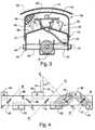
- Lower front feed roll 20shown in detail in Fig. 2, includes a stationary shaft 31 on which the feed roll is journaled for rotation in bearing assemblies 32, 33 suitably mounted in feed roll end caps 34, 35.
- a generally tubular non-ferrous outer wall 36 of the feed rollis secured to end caps 34, 35 by fastening means 37, 38.
- a series of radial aggressive non-ferrous flange elements 39are provided for engaging and feeding the mat of crop material in the usual manner.
- a splined stub drive shaft 40is contained by a collar 41 forming an integral part of end cap 35.
- drive shaft 40When drive shaft 40 is rotated by a feed drive mechanism (not shown) of the forage harvester, the drive force rotates feed roll end caps 34, 35 and the tubular outer wall 36 of the feed roll. Bearings 32, 33 permit rotation of the end caps even though the shaft 31 remains stationary.
- the left end of shaft 31, as viewed in Fig. 2may be keyed to a support block affixed to the frame of the forage harvester as shown in US-A-4 353 199.
- a metal detector assembly 42is mounted on the stationary shaft 31 as described in US-A-4 433 528.
- the detector assembly 42includes a cover plate 43, preferably made of aluminum or another non-ferrous material, and a mounting frame 44 which serve to support and cover a plurality of magnets 54, 56, 58, 60, 62 and 64 and a printed circuit board 66.
- Mounting frame 44is secured to fixed shaft 31 by a series of bolts 46 and nuts 47 spaced by spacers 48, 50 disposed between the inner surface of frame 44 and shaft 31.
- Cover plate 43is secured to, and aligned with, the outer surface of mounting frame 44 by a series of metal screws 51.
- the printed circuit board 66carries a plurality of Hall effect transducers 74, 76, 78, 80 and 82 and circuitry for the processing of signals generated by the metal detector.
- the magnets 54, 56, 58, 60, 62 and 64are mounted on surfaces 52 and 53 of mounting frame 44.
- the printed circuit board 66surmounts the magnets.
- Cover plate 43 and mounting frame 44form an enclosed region which is filled with an encapsulating material 49 such as an epoxy or urethane. For the sake of clarity, only a portion of the encapsulating material is shown in Fig. 3.
- a cable 55extends from the printed circuit board 66 through an axial opening in stationary shaft 31.
- the cable 55includes leads for supplying voltages to the circuits on board 66 and leads for conveying output signals from the circuits on the board to circuits external to the feed roll.
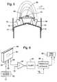
- Fig. 4is a top view showing the arrangement of magnets 54, 56, 58, 60, 62 and 64 and the transducers 74, 76, 78, 80 and 82.
- the magnetsmay be electromagnets or permanent magnets, permanent magnets being shown to avoid the necessity of showing energizing windings.
- the number of magnetsmay vary depending on the application.
- the magnetsare arranged in two rows extending traverse to the crop feed path represented by arrow 57 (Fig. 4) the magnets of one row having a North pole adjacent board 66 and the magnets of the second row having a South pole adjacent the board as best seen in Fig. 5.
- the transducers 74, 76, 78, 80, 82may be pluggable modules such as the model 3503 ratiometric, linear Hall effect sensor sold commercially by Allegro Microsystems, Inc. These pluggable units include a Hall sensing element, linear amplifier and an emitter-follower output stage.
- Fig. 6includes a perspective view of a module 82 having a sensing element 84 which is a planar conductive film.
- sensing element 84when sensing element 84 is placed in a magnetic field perpendicular to its plane, and a direct current is caused to flow through the sensing element from one side to the opposite side, an electric field is produced in the plane of the sensing element in a direction perpendicular to current flow, the intensity of the electric field being proportional to the magnetic field density.
- Fig. 4where flux lines are shown extending from the magnet 58 to the magnets 54 and 56.
- Fig. 5is a schematic elevation of magnets 54 and 58 and shows that the flux lines between these magnets extend outwardly into the crop feed path represented by arrow 57.
- Each transducer 74, 76, 78, 80, 82is disposed such that its sensing element intercepts flux lines extending between the magnets of a set, that is, between the North pole of a magnet in one row and the South pole of a magnet in the other row.
- Each sensing elementshould be in a plane perpendicular to the flux lines passing through it, or as nearly perpendicular as possible.
- the transducersin addition to being positioned so that their sensing elements 84 are at an angle with respect to the direction of crop feed as shown in Fig. 4, are oriented such that the planes of the sensing elements are normal to the crop feed path as shown in Fig. 5.
- the magnetsWhen the magnets and the transducers are disposed as described above, the magnets create a magnetic detection field extending into and across the crop feed path, the detection field comprising a plurality of magnetic fields with each field extending between a set of magnets which includes a magnet in each row. Each field of the plurality of fields has flux lines extending through a transducer in a direction generally normal to the plane of the Hall sensing element therein.
- the flux density through one or more of the sensing elementsis varied and it or they produce output signals.
- a typical transducer module 82has three pins 88 which are inserted into board 66. One pin is connected to ground and a second pin 88 is connected to a current source 90 which causes direct current flow through the sensing element 84 in the transducer.
- the third pin or signal output pin 88is connected to an amplifier 92 in a signal processing channel which also includes a low-pass filter circuit 94 and a threshold detector 96.
- the filter circuit 94which is designed to filter from the transducer output signal the higher frequency noise caused by movement of ferrous machine parts such as gear teeth near the region of the detection field.
- the filtered signalis then applied to a threshold detector which compares the filtered signal with a reference voltage V R .
- the threshold detectoris set so that noise generated by moving machine parts will not cause the detector to produce an output signal.
- sensing element 84When tramp metal passes through the magnetic field in which sensing element 84 is disposed, it varies the magnetic field so that the sensing element produces an output signal. After amplification by amplifier 92 and filtering by filter circuit 94, the output signal triggers threshold detector 96 and the detector produces an output signal to energize a feed stop mechanism 98.
- the feed stop mechanismis conventional and may, for example, be of the type disclosed in US-A-5 078 645.
- Fig. 6shows only one signal processing channel, it will be understood that a signal processing channel is provided for each of the transducers 74, 76, 78, 80 and 82, the channels all having outputs connected to the feed stop mechanism 98.
- the present inventionprovides a metal detector which requires less space than prior art detectors used to detect tramp metal in the crop feed path of an agricultural harvester. Since the magnets may be mounted underneath the printed circuit board and no space is required above the board for bulky sensing coils, the printed circuit board may be raised considerably, limited only by the circuitry and transducers mounted thereon. Thus, even though the magnets are mounted below the circuit board, they may in effect be located closer to the internal periphery of the feed roll so that their detection fields may extend further into and across the crop feed path.
- the magnetsbe located below the circuit board. They may be located on the top surface of the circuit board or even on a separate support. However, mounting of the magnets below the board has an advantage in that the board may then provide the support for the transducer elements.
- the magnets and transducer elementsneed not be mounted within a feed roll although this location has the advantage of protecting the detecting apparatus while permitting the disposition of the magnets closely adjacent the crop feed path.
- the present inventionis suitable for use in other positions such as under a floor plate adjacent the crop feed path as suggested in US-A-4 344 074.
Landscapes
- Life Sciences & Earth Sciences (AREA)
- Environmental Sciences (AREA)
- Harvesting Machines For Root Crops (AREA)
- Geophysics And Detection Of Objects (AREA)
Description
- The present invention relates to metal detectors andmore particularly to metal detectors for detecting ferrousmaterial in crop harvesting machines.
- A typical harvesting machine, such as a forageharvester, may include an attachment mounted on the frontend of the harvester for cutting and/or gathering cropmaterial and feeding it into a basic processing unit. Thebasic unit includes feed rolls for advancing the cropmaterial, compressing it into a mat, and feeding it into acutterhead. The cutterhead generally comprises a pluralityof knives mounted on a rotating reel, the knivescooperating with a stationary shear bar to chop the cropmaterial. The crop material is then discharged from theharvester.
- Tramp metal such as fencing stakes, nuts and boltsdetached from other equipment, tools which have been leftin the field or bounced out of moving machines, etc. isfrequently picked up from the field with the crop material.The tramp metal, if it reaches the cutterhead, damages theshear bar and cutterhead knives. The problem of tramp metalin crop material being processed by agricultural harvestingequipment moving across farm fields is well known and muchtime and money has been expended in efforts to solve theproblem.
- One conventional way to alleviate the problems causedby tramp metal has been to provide a magnetic metaldetector within one of the feed rolls which feeds the cropmaterial toward the cutterhead. Metal passing in proximityto the feed roll varies a magnetic field generated by thedetector and circuits are provided for detecting variationsin the magnetic field and stopping the feeder mechanismwhen a variation is detected, thereby preventing metalobjects from being fed into the cutterhead.
- Many types of magnetic metal detectors have beendevised in efforts to obtain a detector which isinexpensive and easily manufactured, at the same time beingsmall enough to be located within a feed roll and sensitiveenough to detect smaller metal objects such as nails, nutsand bolts anywhere over the lateral extent of the crop feedpath. Various forms of prior art metal detectors aredisclosed in US-A-3 972 156, US-A-3 757 501, US-A-3 889249, US-A-4 290 255, US-A-4 433 528, US-A-5 070 682, US-A-5078 645, US-A-5 092 818, US-A-4 344 074 and US-A-4 788 813.These detectors typically include a plurality ofelectromagnets or permanent magnets for producing amagnetic detection field and sensing coils for sensingchanges in the magnetic field produced by metal objectspassing through the crop feed path. Each coil may comprisea thousand turns of insulated wire. The coils are bulky andonly limited space is available within the feed roll toaccommodate them. Furthermore, to prevent wear of the coilinsulation due to rubbing as a result of harvestervibrations, insulating pads are required between the coilsand the magnets and between the coils and the housingenclosing the detector.
- It is an object of the present invention to provide amagnetic metal detector for a harvesting machine, the metaldetector requiring less space than prior art detectors. Thereplacement of plural turn sensing coils with smallersensing elements results in a magnetic metal detector whichis easily accommodated within a feed roll of a harvester.The smaller volumes of the new sensing elements permit theraising of the magnets, such that they may be locatedcloser to the crop feed path for improved sensing action.
- According to the invention an apparatus is providedfor detecting the passage of ferrous metal objects throughthe crop feed path of an agricultural harvester, havingfeed means for feeding crop material along said crop feedpath, said apparatus comprising:
- magnets means disposed adjacent said crop feed path such that a magnetic field produced by said magnet means istraversed by crop material and any ferrous material objectstherein being fed along the crop feed path, said ferrousmetal objects causing variations in said magnetic field;and
- sensing means operable to produce an output signalwhen a ferrous metal object traverses said magnetic field.
- Such an apparatus is known from US-A-4 433 528.
- Said detection apparatus is characterized in that saidsensing means comprises at least one generally planar Hallsensing element, disposed in said magnetic field and saiddetection apparatus further comprises means for causing adirect current to flow through said Hall sensing element.
- Preferably the magnet means comprises a first group ofpermanent magnets having South poles facing the crop feedpath and a second group having North poles facing the same.Hall sensing elements may be disposed between each magnetof the first group and an adjacent magnet of the secondgroup in planes normal to the crop feed path and extendingat a substantial angle relative to the direction of cropfeed. The sensing elements may be mounted on a circuitboard mounted between the magnets and crop feed path.Magnets and circuit board may be disposed in an enclosedhousing, filled with encapsulating material, within a feedroll of the feed means. The signal from the sensingelements when the passage of a ferrous object is detected,can be used for stopping the feed means.
- Fig. 1 is a schematic view of a forage harvester inwhich the invention may be used;
- Fig. 2 is a part sectional view taken along the line2-2 of Fig. 1 and illustrating the mounting of a metaldetector inside a feed roll;
- Fig. 3 is a sectional view taken along the line 3-3 ofFig. 2 and illustrating the mounting of a metal detectorand a circuit board inside of a feed roll;
- Fig. 4 is a schematic plan view of a circuit boardsurmounting a plurality of permanent magnets, the view alsoillustrating magnetic lines of flux produced between sets of the magnets;
- Fig. 5 is a diagrammatic elevation view illustratingthe relationship between the detection field generated bythe metal detector and the crop feed path; and,
- Fig. 6 is a perspective view of a transducer module,the view including a block diagram of a signal processingcircuit for processing the output signal from the module.
- Fig. 1 illustrates an improved forage harvestingmachine of the kind in which the present invention may beemployed. It is apparent that the invention may also beemployed with benefit for the protection of other types offarm machinery. The representative farm machine illustratedin Fig. 1 may be similar to the forage harvester in US-A-3523 411 and US-A-3 959 953.
- The forage harvester, generally designated by
reference numeral 10, comprises abase unit 11 and anattachment 12 for gathering crop material and feeding it tothebase unit 11 for processing.Attachment 12 directlycuts crop material in the field and feeds it tobase unit 11 where it is chopped and eventually conveyed to atrailing forage wagon (not shown). A direct cut attachmentis shown for exemplary purposes but in actual practice anytype of attachment, e.g. a row crop unit or a windrow pick-up,could be used with a base unit of the type showninsofar as the present invention is concerned. - More particularly, the attachment shown includes a
reel 13, depicted in phantom outline, which operates in aconventional manner to guide material over acutter bar 14and up aninclined floor 15 to aconsolidating auger 16,also depicted in phantom outline.Attachment 12 ispivotally mounted tobase unit 11 at 17 and is adapted tofeed crop material to the space between upper and lowerfront feed rolls rearfeed rolls conveyor 24 commonly comprises an auger mounted transversely for feeding the chopped cropmaterial to a blower unit which conveys it upwardly via avertical spout 25 (partially shown) and then rearwardly toa trailing forage wagon. - The front and rear pairs of upper and
lower feed rolls auger 16. The mat of material is fedrearwardly across the top surface of ashearbar 26 which isoperatively associated with a series of cutting elements 27(one of which is shown in phantom) on a rotatingcutterhead 23 journaled for rotation by amounting assembly 28 insidewall 30 ofbase unit 11. - The present invention is directed to apparatus fordetecting ferrous metal objects in the crop material beingfed to
cutterhead 23, and more particularly, it isconcerned with detection means mounted in the lowerfrontfeed roll 20 for detecting metal objects in the compressedmat and initiating a control signal in response thereto fordiscontinuing transport of the crop material prior tointroduction of the sensed object into the area at whichtheshearbar 26 andcutterhead 23 cooperatively engage andcut the crop. - Lower
front feed roll 20, shown in detail in Fig. 2,includes astationary shaft 31 on which the feed roll isjournaled for rotation inbearing assemblies roll end caps outer wall 36 of the feed roll issecured toend caps non-ferrous flange elements 39are provided for engaging and feeding the mat of cropmaterial in the usual manner. - A splined
stub drive shaft 40 is contained by acollar 41 forming an integral part ofend cap 35. Whendrive shaft 40 is rotated by a feed drive mechanism (not shown) of theforage harvester, the drive force rotates feedroll endcaps outer wall 36 of the feed roll.Bearings shaft 31 remains stationary. In this regard, the leftend ofshaft 31, as viewed in Fig. 2, may be keyed to asupport block affixed to the frame of the forage harvesteras shown in US-A-4 353 199. - Referring to Figs. 3 and 4, a
metal detector assembly 42 is mounted on thestationary shaft 31 as described inUS-A-4 433 528. Thedetector assembly 42 includes acoverplate 43, preferably made of aluminum or another non-ferrousmaterial, and amounting frame 44 which serve tosupport and cover a plurality ofmagnets circuit board 66.Mounting frame 44 issecured to fixedshaft 31 by a series ofbolts 46 andnuts 47 spaced byspacers frame 44 andshaft 31.Cover plate 43 is securedto, and aligned with, the outer surface ofmounting frame 44 by a series ofmetal screws 51. The printedcircuitboard 66 carries a plurality ofHall effect transducers - The
magnets surfaces mounting frame 44. The printedcircuit board 66 surmounts the magnets.Cover plate 43 andmountingframe 44 form an enclosed region which is filledwith anencapsulating material 49 such as an epoxy orurethane. For the sake of clarity, only a portion of theencapsulating material is shown in Fig. 3. Acable 55extends from theprinted circuit board 66 through an axialopening instationary shaft 31. Thecable 55 includes leadsfor supplying voltages to the circuits onboard 66 andleads for conveying output signals from the circuits on theboard to circuits external to the feed roll. - Fig. 4 is a top view showing the arrangement of
magnets transducers adjacent board 66 and themagnets of the second row having a South pole adjacent theboard as best seen in Fig. 5. - The
transducers module 82 having asensing element 84 which is a planar conductive film.According to Hall effect theory, when sensingelement 84 isplaced in a magnetic field perpendicular to its plane, anda direct current is caused to flow through the sensingelement from one side to the opposite side, an electricfield is produced in the plane of the sensing element in adirection perpendicular to current flow, the intensity ofthe electric field being proportional to the magnetic fielddensity. - The placement of the magnets is such that flux linesare established between a magnet in one row and the twomagnets closest thereto in the second row. This isillustrated in Fig. 4 where flux lines are shown extendingfrom the
magnet 58 to themagnets magnets arrow 57. - Each
transducer alternate transducers transducers - The transducers, in addition to being positioned sothat their
sensing elements 84 are at an angle with respectto the direction of crop feed as shown in Fig. 4, areoriented such that the planes of the sensing elements arenormal to the crop feed path as shown in Fig. 5. - When the magnets and the transducers are disposed asdescribed above, the magnets create a magnetic detectionfield extending into and across the crop feed path, thedetection field comprising a plurality of magnetic fieldswith each field extending between a set of magnets whichincludes a magnet in each row. Each field of the pluralityof fields has flux lines extending through a transducer ina direction generally normal to the plane of the Hallsensing element therein. Thus, when a ferrous metal objectbeing fed along the crop feed path passes through one ormore of the plurality of magnetic fields, the flux densitythrough one or more of the sensing elements is varied andit or they produce output signals.
- In Fig. 6, a
typical transducer module 82 has threepins 88 which are inserted intoboard 66. One pin isconnected to ground and asecond pin 88 is connected to acurrent source 90 which causes direct current flow throughthesensing element 84 in the transducer. The third pin orsignal output pin 88 is connected to anamplifier 92 in asignal processing channel which also includes a low-passfilter circuit 94 and athreshold detector 96. - After the output signal from
transducer 82 is amplified byamplifier 92 it is applied to thefiltercircuit 94 which is designed to filter from the transduceroutput signal the higher frequency noise caused by movementof ferrous machine parts such as gear teeth near the regionof the detection field. The filtered signal is then appliedto a threshold detector which compares the filtered signalwith a reference voltage VR. The threshold detector is setso that noise generated by moving machine parts will notcause the detector to produce an output signal. - When tramp metal passes through the magnetic field inwhich
sensing element 84 is disposed, it varies themagnetic field so that the sensing element produces anoutput signal. After amplification byamplifier 92 andfiltering byfilter circuit 94, the output signal triggersthreshold detector 96 and the detector produces an outputsignal to energize afeed stop mechanism 98. The feed stopmechanism is conventional and may, for example, be of thetype disclosed in US-A-5 078 645. - Although Fig. 6 shows only one signal processingchannel, it will be understood that a signal processingchannel is provided for each of the
transducers feed stop mechanism 98. - From the foregoing description it is seen that thepresent invention provides a metal detector which requiresless space than prior art detectors used to detect trampmetal in the crop feed path of an agricultural harvester.Since the magnets may be mounted underneath the printedcircuit board and no space is required above the board forbulky sensing coils, the printed circuit board may beraised considerably, limited only by the circuitry andtransducers mounted thereon. Thus, even though the magnetsare mounted below the circuit board, they may in effect belocated closer to the internal periphery of the feed rollso that their detection fields may extend further into andacross the crop feed path.
- It is not essential that the magnets be located below the circuit board. They may be located on the top surfaceof the circuit board or even on a separate support.However, mounting of the magnets below the board has anadvantage in that the board may then provide the supportfor the transducer elements.
- Furthermore, the magnets and transducer elements neednot be mounted within a feed roll although this locationhas the advantage of protecting the detecting apparatuswhile permitting the disposition of the magnets closelyadjacent the crop feed path. However, the present inventionis suitable for use in other positions such as under afloor plate adjacent the crop feed path as suggested in US-A-4344 074.
Claims (13)
- Apparatus (42) for detecting the passage offerrous metal objects through the crop feed path (57)of an agricultural harvester (10), having feed means(18, 20, 21, 22) for feeding crop material along saidcrop feed path (57), said apparatus (42) comprising:magnets means (54, 56, 58, 60, 62, 64) disposedadjacent said crop feed path (57) such that a magneticfield produced by said magnet means (54, 56, 58, 60,62, 64) is traversed by crop material and any ferrousmaterial objects therein being fed along the crop feedpath (57), said ferrous metal objects causingvariations in said magnetic field; andsensing means (74, 76, 78, 80, 82) operable toproduce an output signal when a ferrous metal objecttraverses said magnetic field;said detection apparatus (42) being characterizedin that:said sensing means (74, 76, 78, 80, 82) comprisesat least one generally planar Hall sensing element(84), disposed in said magnetic field; andsaid detection apparatus (42) further comprisesmeans (90) for causing a direct current to flowthrough said Hall sensing element (84).
- An apparatus (42) according to claim 1,characterized in that said at least one Hall sensingelement (84) is disposed, such that the magnetic fieldproduced by said magnet means (54, 56, 58, 60, 62, 64)extends through the Hall sensing element (84) in adirection normal to the plane (P1, P2) of the Hallsensing element (84).
- An apparatus (42) according to claim 1 or 2,characterized in that:said magnet means comprises a first group ofmagnets (54, 56, 62) having South poles facinggenerally toward said crop feed path (57) and a secondgroup of magnets (58, 60, 64) having North poles alsofacing generally toward said crop feed path (57); andsaid at least one Hall sensing element (84) isdisposed between a magnet (56) of said first group ofmagnets (54, 56, 62) and an adjacent magnet (58) ofsaid second group of magnets (58, 60, 64).
- An apparatus (42) according to claim 3,characterized in that said first group of magnets (54,56, 62) and second group of magnets (58, 60, 64) aredisposed transverse to the direction of crop feed andarranged such that magnetic lines of flux extendbetween each magnet of said first group (54, 56, 62)and at least one magnet of said second group (58, 60,64).
- An apparatus (42) according to claim 4characterized in that said at least one Hall sensingelement (48) is disposed in a plane (P1, P2) normal tothe crop feed path (57).
- An apparatus (42) according to claim 5,characterized in that said plane (P1, P2) extends ata substantial angle (α, β) relative to the directionof crop feed.
- An apparatus (42) according to any of thepreceding claims, characterized in that said at least one Hall sensing element (84) is mounted on a circuitboard (66).
- An apparatus (42) according to claim 7,characterized in that said circuit board (66) isdisposed between the magnet means (54, 56, 58, 60, 62,64) and the crop feed path (57).
- An apparatus (42) according to claim 7 or 8,characterized in that the feed means (18, 20, 21, 22)comprises at least one feed roll (20) and said circuitboard (66) and said magnet means (54, 56, 58, 60, 62,64) are disposed within said at least one feed roll(20).
- An apparatus (42) according to claim 9,characterized in that said circuit board (66) and saidmagnet means (54, 56, 58, 60, 62, 64) are supportedwithin an enclosed housing (43, 44) within said atleast one feed roll (20).
- An apparatus (42) according to claim 10,characterized in that said enclosed housing (43, 44)is filled with an encapsulating material (49).
- An apparatus (42) according to any of thepreceding claims, characterized in that said magnetmeans comprises permanent magnets (54, 56, 58, 60, 62,64).
- An apparatus (42) according to any of thepreceding claims, characterized in that it comprisesmeans (92, 94, 96, 98) responsive to the output signalfrom said at least one Hall sensing element (84) forstopping the feed means (18, 20, 21, 22) when thepassage of a ferrous metal object through the magneticfield is detected.
Applications Claiming Priority (2)
| Application Number | Priority Date | Filing Date | Title |
|---|---|---|---|
| US191181 | 1994-02-03 | ||
| US08/191,181US5444966A (en) | 1994-02-03 | 1994-02-03 | Metal detection apparatus for agricultural harvester |
Publications (2)
| Publication Number | Publication Date |
|---|---|
| EP0666021A1 EP0666021A1 (en) | 1995-08-09 |
| EP0666021B1true EP0666021B1 (en) | 1999-04-28 |
Family
ID=22704443
Family Applications (1)
| Application Number | Title | Priority Date | Filing Date |
|---|---|---|---|
| EP95200209AExpired - LifetimeEP0666021B1 (en) | 1994-02-03 | 1995-01-28 | Metal detection apparatus for an agricultural harvester |
Country Status (3)
| Country | Link |
|---|---|
| US (1) | US5444966A (en) |
| EP (1) | EP0666021B1 (en) |
| DE (1) | DE69509271T2 (en) |
Cited By (1)
| Publication number | Priority date | Publication date | Assignee | Title |
|---|---|---|---|---|
| DE19620526A1 (en)* | 1996-05-22 | 1997-11-27 | Burkhard Weis | Metal detector for sensing ferromagnetic metal in harvesting machine |
Families Citing this family (12)
| Publication number | Priority date | Publication date | Assignee | Title |
|---|---|---|---|---|
| DE4211545C1 (en)* | 1992-04-06 | 1993-08-05 | Hans-Juergen 7400 Tuebingen De Maier | |
| US5521514A (en)* | 1995-01-03 | 1996-05-28 | Loral Corporation | Broken tine detector for agricultural machines |
| US5797250A (en)* | 1996-09-27 | 1998-08-25 | Deere & Company | Forage harvester feed roll assembly designed for minimizing false tripping of a metal detector system |
| DE19735698A1 (en)* | 1997-08-16 | 1999-02-18 | Deere & Co | Connection of counter-blade and counter-blade holder in crushing device of agricultural harvesting machine like chaff-cutter |
| DE20023334U1 (en) | 2000-03-08 | 2003-10-09 | Mesutronic Gerätebau GmbH, 94259 Kirchberg | Detector for sensing metal parts in nonconductive conveyed material, uses vectorial addition circuit to add signals from two or more sensors arranged along conveyor |
| US6601372B1 (en)* | 2002-02-22 | 2003-08-05 | New Holland North America, Inc. | Stone detection method and apparatus for harvester |
| US7489128B2 (en) | 2002-03-11 | 2009-02-10 | Kopp Keith A | MRI protector |
| DE10348659A1 (en)* | 2003-10-15 | 2005-06-30 | Claas Selbstfahrende Erntemaschinen Gmbh | Conveyor with a metal detection device |
| GB2430036A (en)* | 2005-09-09 | 2007-03-14 | Cnh Belgium Nv | Metal detector arrangement |
| DE102007025310A1 (en)* | 2007-05-30 | 2008-12-04 | Claas Selbstfahrende Erntemaschinen Gmbh | Agricultural harvester with a foreign object detection device |
| US7748206B1 (en) | 2009-03-10 | 2010-07-06 | Cnh America Llc | Fruit harvester with system and method for detecting and reducing forces exerted against rigid standing objects |
| US7994653B2 (en)* | 2009-03-18 | 2011-08-09 | Lineage Power Corporation | Pluggable power management module for a power distribution panel |
Family Cites Families (12)
| Publication number | Priority date | Publication date | Assignee | Title |
|---|---|---|---|---|
| US3889249A (en)* | 1971-10-29 | 1975-06-10 | Sperry Rand Corp | Static magnetic field metal detector |
| US3757501A (en)* | 1971-10-29 | 1973-09-11 | Sperry Rand Corp | Static magnetic field metal detector |
| US3972156A (en)* | 1975-02-24 | 1976-08-03 | Sperry Rand Corporation | Speed-independent static magnetic field metal detector |
| US4066962A (en)* | 1976-12-08 | 1978-01-03 | The Singer Company | Metal detecting device with magnetically influenced Hall effect sensor |
| JPS5631806A (en)* | 1979-08-24 | 1981-03-31 | Pioneer Electronic Corp | Extraneous metal detector for automobile tire |
| US4290255A (en)* | 1980-10-01 | 1981-09-22 | Sperry Corporation | Feed roll apparatus |
| US4344074A (en)* | 1981-04-02 | 1982-08-10 | Sperry Corporation | Magnetic field producing apparatus |
| US4433528A (en)* | 1982-08-30 | 1984-02-28 | Sperry Corporation | Metal detector apparatus |
| US4788813A (en)* | 1988-01-13 | 1988-12-06 | Ford New Holland, Inc. | Metal detection in the vicinity of ferrous boundaries |
| US5078645A (en)* | 1990-10-26 | 1992-01-07 | Ford New Holland, Inc. | Method and apparatus for hard object detection |
| US5092818A (en)* | 1990-10-26 | 1992-03-03 | Ford New Holland, Inc. | Metal and hard object detectors with shared fixed support inside a feed roll |
| US5070682A (en)* | 1990-10-26 | 1991-12-10 | Ford New Holland, Inc. | Acoustic detector with start-up control |
- 1994
- 1994-02-03USUS08/191,181patent/US5444966A/ennot_activeExpired - Lifetime
- 1995
- 1995-01-28EPEP95200209Apatent/EP0666021B1/ennot_activeExpired - Lifetime
- 1995-01-28DEDE69509271Tpatent/DE69509271T2/ennot_activeExpired - Lifetime
Cited By (1)
| Publication number | Priority date | Publication date | Assignee | Title |
|---|---|---|---|---|
| DE19620526A1 (en)* | 1996-05-22 | 1997-11-27 | Burkhard Weis | Metal detector for sensing ferromagnetic metal in harvesting machine |
Also Published As
| Publication number | Publication date |
|---|---|
| US5444966A (en) | 1995-08-29 |
| DE69509271T2 (en) | 1999-08-12 |
| DE69509271D1 (en) | 1999-06-02 |
| EP0666021A1 (en) | 1995-08-09 |
Similar Documents
| Publication | Publication Date | Title |
|---|---|---|
| EP0102665B1 (en) | Metal detector apparatus | |
| EP0666021B1 (en) | Metal detection apparatus for an agricultural harvester | |
| US3972156A (en) | Speed-independent static magnetic field metal detector | |
| US3959953A (en) | Apparatus to detect the passage of ferrous material in crop harvesting machines | |
| US4344074A (en) | Magnetic field producing apparatus | |
| US3889249A (en) | Static magnetic field metal detector | |
| US3757501A (en) | Static magnetic field metal detector | |
| US5979153A (en) | Agricultural baler | |
| EP1762134B1 (en) | Metal detector arrangement | |
| US4353199A (en) | Stone detector for harvesting machines | |
| US3896608A (en) | Static magnetic field metal detector | |
| US4322937A (en) | Harvester with internal metal detector | |
| CA2456404C (en) | Device for measuring and/or checking the distance between a shearbar and a chopping knife | |
| US5092818A (en) | Metal and hard object detectors with shared fixed support inside a feed roll | |
| EP2040096B1 (en) | Foreign object detection system for agricultural harvesting machines | |
| US4758788A (en) | Metal detector for intake of field chopper | |
| US4720963A (en) | Method of detecting stones in the intake of a field chopper | |
| US5070682A (en) | Acoustic detector with start-up control | |
| US20080078153A1 (en) | Foreign Body Detector For An Agricultural Harvester | |
| EP0324253B1 (en) | Metal detection in the vicinity of ferrous boundaries | |
| US7064540B2 (en) | Conveyor with a metal detecting device | |
| US5979150A (en) | Connection of a shear bar to shear bar support of a forage harvester | |
| US5078645A (en) | Method and apparatus for hard object detection | |
| EP1498019A1 (en) | Harvester with a metal detecting device |
Legal Events
| Date | Code | Title | Description |
|---|---|---|---|
| PUAI | Public reference made under article 153(3) epc to a published international application that has entered the european phase | Free format text:ORIGINAL CODE: 0009012 | |
| AK | Designated contracting states | Kind code of ref document:A1 Designated state(s):DE DK FR GB IT NL | |
| 17P | Request for examination filed | Effective date:19960122 | |
| GRAG | Despatch of communication of intention to grant | Free format text:ORIGINAL CODE: EPIDOS AGRA | |
| 17Q | First examination report despatched | Effective date:19980805 | |
| GRAG | Despatch of communication of intention to grant | Free format text:ORIGINAL CODE: EPIDOS AGRA | |
| GRAH | Despatch of communication of intention to grant a patent | Free format text:ORIGINAL CODE: EPIDOS IGRA | |
| GRAH | Despatch of communication of intention to grant a patent | Free format text:ORIGINAL CODE: EPIDOS IGRA | |
| GRAA | (expected) grant | Free format text:ORIGINAL CODE: 0009210 | |
| AK | Designated contracting states | Kind code of ref document:B1 Designated state(s):DE DK FR GB IT NL | |
| PG25 | Lapsed in a contracting state [announced via postgrant information from national office to epo] | Ref country code:NL Free format text:LAPSE BECAUSE OF FAILURE TO SUBMIT A TRANSLATION OF THE DESCRIPTION OR TO PAY THE FEE WITHIN THE PRESCRIBED TIME-LIMIT Effective date:19990428 | |
| REF | Corresponds to: | Ref document number:69509271 Country of ref document:DE Date of ref document:19990602 | |
| ET | Fr: translation filed | ||
| PG25 | Lapsed in a contracting state [announced via postgrant information from national office to epo] | Ref country code:DK Free format text:LAPSE BECAUSE OF FAILURE TO SUBMIT A TRANSLATION OF THE DESCRIPTION OR TO PAY THE FEE WITHIN THE PRESCRIBED TIME-LIMIT Effective date:19990728 | |
| PLBE | No opposition filed within time limit | Free format text:ORIGINAL CODE: 0009261 | |
| STAA | Information on the status of an ep patent application or granted ep patent | Free format text:STATUS: NO OPPOSITION FILED WITHIN TIME LIMIT | |
| 26N | No opposition filed | ||
| REG | Reference to a national code | Ref country code:GB Ref legal event code:IF02 | |
| REG | Reference to a national code | Ref country code:FR Ref legal event code:CD | |
| PGFP | Annual fee paid to national office [announced via postgrant information from national office to epo] | Ref country code:IT Payment date:20120126 Year of fee payment:18 | |
| PGFP | Annual fee paid to national office [announced via postgrant information from national office to epo] | Ref country code:DE Payment date:20130108 Year of fee payment:19 Ref country code:GB Payment date:20130111 Year of fee payment:19 Ref country code:FR Payment date:20130207 Year of fee payment:19 | |
| PG25 | Lapsed in a contracting state [announced via postgrant information from national office to epo] | Ref country code:IT Free format text:LAPSE BECAUSE OF NON-PAYMENT OF DUE FEES Effective date:20130128 | |
| REG | Reference to a national code | Ref country code:DE Ref legal event code:R119 Ref document number:69509271 Country of ref document:DE | |
| GBPC | Gb: european patent ceased through non-payment of renewal fee | Effective date:20140128 | |
| PG25 | Lapsed in a contracting state [announced via postgrant information from national office to epo] | Ref country code:DE Free format text:LAPSE BECAUSE OF NON-PAYMENT OF DUE FEES Effective date:20140801 | |
| REG | Reference to a national code | Ref country code:FR Ref legal event code:ST Effective date:20140930 | |
| REG | Reference to a national code | Ref country code:DE Ref legal event code:R119 Ref document number:69509271 Country of ref document:DE Effective date:20140801 | |
| PG25 | Lapsed in a contracting state [announced via postgrant information from national office to epo] | Ref country code:FR Free format text:LAPSE BECAUSE OF NON-PAYMENT OF DUE FEES Effective date:20140131 Ref country code:GB Free format text:LAPSE BECAUSE OF NON-PAYMENT OF DUE FEES Effective date:20140128 |