EP0665590B1 - Process for manufacturing a microstructure - Google Patents
Process for manufacturing a microstructureDownload PDFInfo
- Publication number
- EP0665590B1 EP0665590B1EP95300521AEP95300521AEP0665590B1EP 0665590 B1EP0665590 B1EP 0665590B1EP 95300521 AEP95300521 AEP 95300521AEP 95300521 AEP95300521 AEP 95300521AEP 0665590 B1EP0665590 B1EP 0665590B1
- Authority
- EP
- European Patent Office
- Prior art keywords
- substrate
- layer
- sacrificial layer
- process according
- beam member
- Prior art date
- Legal status (The legal status is an assumption and is not a legal conclusion. Google has not performed a legal analysis and makes no representation as to the accuracy of the status listed.)
- Expired - Lifetime
Links
- 238000000034methodMethods0.000titleclaimsdescription84
- 238000004519manufacturing processMethods0.000titledescription5
- 239000010410layerSubstances0.000claimsdescription417
- 239000000758substrateSubstances0.000claimsdescription355
- 229920002120photoresistant polymerPolymers0.000claimsdescription71
- 239000000463materialSubstances0.000claimsdescription27
- 229910052751metalInorganic materials0.000claimsdescription26
- 239000002184metalSubstances0.000claimsdescription26
- 239000011347resinSubstances0.000claimsdescription20
- 229920005989resinPolymers0.000claimsdescription20
- 238000001312dry etchingMethods0.000claimsdescription14
- 239000002243precursorSubstances0.000claimsdescription14
- 239000002904solventSubstances0.000claimsdescription12
- 238000010438heat treatmentMethods0.000claimsdescription11
- QVGXLLKOCUKJST-UHFFFAOYSA-Natomic oxygenChemical compound[O]QVGXLLKOCUKJST-UHFFFAOYSA-N0.000claimsdescription9
- 239000001301oxygenSubstances0.000claimsdescription9
- 229910052760oxygenInorganic materials0.000claimsdescription9
- 239000012790adhesive layerSubstances0.000claimsdescription7
- 229920001971elastomerPolymers0.000claimsdescription7
- 239000005060rubberSubstances0.000claimsdescription7
- 239000012212insulatorSubstances0.000claimsdescription6
- 125000006850spacer groupChemical group0.000claimsdescription6
- 238000000059patterningMethods0.000claimsdescription5
- 239000002178crystalline materialSubstances0.000claimsdescription3
- 230000005686electrostatic fieldEffects0.000claimsdescription3
- 230000003647oxidationEffects0.000claimsdescription2
- 238000007254oxidation reactionMethods0.000claimsdescription2
- 230000001464adherent effectEffects0.000claims1
- 239000002131composite materialSubstances0.000claims1
- 229910052710siliconInorganic materials0.000description56
- 239000010703siliconSubstances0.000description55
- XUIMIQQOPSSXEZ-UHFFFAOYSA-NSiliconChemical compound[Si]XUIMIQQOPSSXEZ-UHFFFAOYSA-N0.000description54
- 239000010408filmSubstances0.000description49
- VYPSYNLAJGMNEJ-UHFFFAOYSA-NSilicium dioxideChemical compoundO=[Si]=OVYPSYNLAJGMNEJ-UHFFFAOYSA-N0.000description46
- 229910052782aluminiumInorganic materials0.000description44
- 239000004411aluminiumSubstances0.000description41
- XAGFODPZIPBFFR-UHFFFAOYSA-NaluminiumChemical compound[Al]XAGFODPZIPBFFR-UHFFFAOYSA-N0.000description41
- 239000011521glassSubstances0.000description33
- 229920003229poly(methyl methacrylate)Polymers0.000description24
- 239000004926polymethyl methacrylateSubstances0.000description24
- 235000012239silicon dioxideNutrition0.000description22
- 239000000377silicon dioxideSubstances0.000description20
- 238000001020plasma etchingMethods0.000description15
- 229910052581Si3N4Inorganic materials0.000description14
- 239000007789gasSubstances0.000description14
- HQVNEWCFYHHQES-UHFFFAOYSA-Nsilicon nitrideChemical compoundN12[Si]34N5[Si]62N3[Si]51N64HQVNEWCFYHHQES-UHFFFAOYSA-N0.000description14
- ZWEHNKRNPOVVGH-UHFFFAOYSA-N2-ButanoneChemical compoundCCC(C)=OZWEHNKRNPOVVGH-UHFFFAOYSA-N0.000description12
- 230000001105regulatory effectEffects0.000description11
- KWYUFKZDYYNOTN-UHFFFAOYSA-MPotassium hydroxideChemical compound[OH-].[K+]KWYUFKZDYYNOTN-UHFFFAOYSA-M0.000description10
- 239000004642PolyimideSubstances0.000description9
- 229920001721polyimidePolymers0.000description9
- 239000000243solutionSubstances0.000description9
- 238000001039wet etchingMethods0.000description9
- KRHYYFGTRYWZRS-UHFFFAOYSA-NFluoraneChemical compoundFKRHYYFGTRYWZRS-UHFFFAOYSA-N0.000description7
- 239000007864aqueous solutionSubstances0.000description7
- 238000005530etchingMethods0.000description7
- 229910000040hydrogen fluorideInorganic materials0.000description7
- 239000003960organic solventSubstances0.000description7
- QTBSBXVTEAMEQO-UHFFFAOYSA-NAcetic acidChemical compoundCC(O)=OQTBSBXVTEAMEQO-UHFFFAOYSA-N0.000description6
- 239000010949copperSubstances0.000description6
- 125000001165hydrophobic groupChemical group0.000description6
- 230000035882stressEffects0.000description6
- MYMOFIZGZYHOMD-UHFFFAOYSA-NDioxygenChemical compoundO=OMYMOFIZGZYHOMD-UHFFFAOYSA-N0.000description5
- 229910021419crystalline siliconInorganic materials0.000description5
- 229910001882dioxygenInorganic materials0.000description5
- 239000000203mixtureSubstances0.000description5
- 229910021420polycrystalline siliconInorganic materials0.000description5
- 229920005591polysiliconPolymers0.000description5
- 239000004065semiconductorSubstances0.000description5
- 239000010409thin filmSubstances0.000description5
- 229910001218Gallium arsenideInorganic materials0.000description4
- NBIIXXVUZAFLBC-UHFFFAOYSA-NPhosphoric acidChemical compoundOP(O)(O)=ONBIIXXVUZAFLBC-UHFFFAOYSA-N0.000description4
- 239000000853adhesiveSubstances0.000description4
- 230000001070adhesive effectEffects0.000description4
- 239000011810insulating materialSubstances0.000description4
- 230000002093peripheral effectEffects0.000description4
- 238000003825pressingMethods0.000description4
- 229910052814silicon oxideInorganic materials0.000description4
- 238000004528spin coatingMethods0.000description4
- 230000003746surface roughnessEffects0.000description4
- WGTYBPLFGIVFAS-UHFFFAOYSA-Mtetramethylammonium hydroxideChemical compound[OH-].C[N+](C)(C)CWGTYBPLFGIVFAS-UHFFFAOYSA-M0.000description4
- QGZKDVFQNNGYKY-UHFFFAOYSA-NAmmoniaChemical compoundNQGZKDVFQNNGYKY-UHFFFAOYSA-N0.000description3
- 229910015844BCl3Inorganic materials0.000description3
- RYGMFSIKBFXOCR-UHFFFAOYSA-NCopperChemical compound[Cu]RYGMFSIKBFXOCR-UHFFFAOYSA-N0.000description3
- GRYLNZFGIOXLOG-UHFFFAOYSA-NNitric acidChemical compoundO[N+]([O-])=OGRYLNZFGIOXLOG-UHFFFAOYSA-N0.000description3
- 239000011248coating agentSubstances0.000description3
- 238000000576coating methodMethods0.000description3
- 239000004020conductorSubstances0.000description3
- 229910052802copperInorganic materials0.000description3
- 238000000313electron-beam-induced depositionMethods0.000description3
- 239000007769metal materialSubstances0.000description3
- 229910052759nickelInorganic materials0.000description3
- 229910017604nitric acidInorganic materials0.000description3
- 238000000206photolithographyMethods0.000description3
- 238000004544sputter depositionMethods0.000description3
- 229910052719titaniumInorganic materials0.000description3
- FAQYAMRNWDIXMY-UHFFFAOYSA-NtrichloroboraneChemical compoundClB(Cl)ClFAQYAMRNWDIXMY-UHFFFAOYSA-N0.000description3
- RZVAJINKPMORJF-UHFFFAOYSA-NAcetaminophenChemical compoundCC(=O)NC1=CC=C(O)C=C1RZVAJINKPMORJF-UHFFFAOYSA-N0.000description2
- 235000021355Stearic acidNutrition0.000description2
- 229910045601alloyInorganic materials0.000description2
- 239000000956alloySubstances0.000description2
- 229910000147aluminium phosphateInorganic materials0.000description2
- 238000004380ashingMethods0.000description2
- 238000005452bendingMethods0.000description2
- 229910052804chromiumInorganic materials0.000description2
- 230000002209hydrophobic effectEffects0.000description2
- 230000005661hydrophobic surfaceEffects0.000description2
- VKOBVWXKNCXXDE-UHFFFAOYSA-Nicosanoic acidChemical compoundCCCCCCCCCCCCCCCCCCCC(O)=OVKOBVWXKNCXXDE-UHFFFAOYSA-N0.000description2
- 238000007654immersionMethods0.000description2
- 150000002500ionsChemical class0.000description2
- 230000001678irradiating effectEffects0.000description2
- 150000002739metalsChemical class0.000description2
- 229910021421monocrystalline siliconInorganic materials0.000description2
- QIQXTHQIDYTFRH-UHFFFAOYSA-Noctadecanoic acidChemical compoundCCCCCCCCCCCCCCCCCC(O)=OQIQXTHQIDYTFRH-UHFFFAOYSA-N0.000description2
- OQCDKBAXFALNLD-UHFFFAOYSA-Noctadecanoic acidNatural productsCCCCCCCC(C)CCCCCCCCC(O)=OOQCDKBAXFALNLD-UHFFFAOYSA-N0.000description2
- VLTRZXGMWDSKGL-UHFFFAOYSA-Nperchloric acidChemical compoundOCl(=O)(=O)=OVLTRZXGMWDSKGL-UHFFFAOYSA-N0.000description2
- 239000005297pyrexSubstances0.000description2
- 239000010453quartzSubstances0.000description2
- 230000005855radiationEffects0.000description2
- 229910001415sodium ionInorganic materials0.000description2
- 239000008117stearic acidSubstances0.000description2
- 238000007738vacuum evaporationMethods0.000description2
- 229910000838Al alloyInorganic materials0.000description1
- 229910000881Cu alloyInorganic materials0.000description1
- DKNPRRRKHAEUMW-UHFFFAOYSA-NIodine aqueousChemical compound[K+].I[I-]IDKNPRRRKHAEUMW-UHFFFAOYSA-N0.000description1
- 229910021578Iron(III) chlorideInorganic materials0.000description1
- HBBGRARXTFLTSG-UHFFFAOYSA-NLithium ionChemical compound[Li+]HBBGRARXTFLTSG-UHFFFAOYSA-N0.000description1
- CDBYLPFSWZWCQE-UHFFFAOYSA-LSodium CarbonateChemical compound[Na+].[Na+].[O-]C([O-])=OCDBYLPFSWZWCQE-UHFFFAOYSA-L0.000description1
- 238000005299abrasionMethods0.000description1
- 239000008186active pharmaceutical agentSubstances0.000description1
- 239000003513alkaliSubstances0.000description1
- 229910052783alkali metalInorganic materials0.000description1
- 150000001340alkali metalsChemical class0.000description1
- 229910021529ammoniaInorganic materials0.000description1
- 239000002585baseSubstances0.000description1
- 150000001555benzenesChemical class0.000description1
- LLCSWKVOHICRDD-UHFFFAOYSA-Nbuta-1,3-diyneChemical groupC#CC#CLLCSWKVOHICRDD-UHFFFAOYSA-N0.000description1
- XMPZTFVPEKAKFH-UHFFFAOYSA-Pceric ammonium nitrateChemical compound[NH4+].[NH4+].[Ce+4].[O-][N+]([O-])=O.[O-][N+]([O-])=O.[O-][N+]([O-])=O.[O-][N+]([O-])=O.[O-][N+]([O-])=O.[O-][N+]([O-])=OXMPZTFVPEKAKFH-UHFFFAOYSA-P0.000description1
- 238000005229chemical vapour depositionMethods0.000description1
- 239000013078crystalSubstances0.000description1
- 238000000354decomposition reactionMethods0.000description1
- 238000001514detection methodMethods0.000description1
- PXBRQCKWGAHEHS-UHFFFAOYSA-NdichlorodifluoromethaneChemical compoundFC(F)(Cl)ClPXBRQCKWGAHEHS-UHFFFAOYSA-N0.000description1
- BUMGIEFFCMBQDG-UHFFFAOYSA-NdichlorosiliconChemical compoundCl[Si]ClBUMGIEFFCMBQDG-UHFFFAOYSA-N0.000description1
- 238000003618dip coatingMethods0.000description1
- 238000004090dissolutionMethods0.000description1
- 238000000609electron-beam lithographyMethods0.000description1
- 238000005516engineering processMethods0.000description1
- 229910052737goldInorganic materials0.000description1
- 230000008642heat stressEffects0.000description1
- 239000012535impuritySubstances0.000description1
- RBTARNINKXHZNM-UHFFFAOYSA-Kiron trichlorideChemical compoundCl[Fe](Cl)ClRBTARNINKXHZNM-UHFFFAOYSA-K0.000description1
- 239000007788liquidSubstances0.000description1
- 229910001416lithium ionInorganic materials0.000description1
- 238000004518low pressure chemical vapour depositionMethods0.000description1
- 239000012528membraneSubstances0.000description1
- 238000005459micromachiningMethods0.000description1
- 239000002120nanofilmSubstances0.000description1
- 229910000069nitrogen hydrideInorganic materials0.000description1
- 229920000642polymerPolymers0.000description1
- 150000003376siliconChemical class0.000description1
- -1sodiumionsChemical class0.000description1
- 239000007787solidSubstances0.000description1
- 238000005507sprayingMethods0.000description1
Images


Classifications
- B—PERFORMING OPERATIONS; TRANSPORTING
- B81—MICROSTRUCTURAL TECHNOLOGY
- B81C—PROCESSES OR APPARATUS SPECIALLY ADAPTED FOR THE MANUFACTURE OR TREATMENT OF MICROSTRUCTURAL DEVICES OR SYSTEMS
- B81C1/00—Manufacture or treatment of devices or systems in or on a substrate
- B81C1/00912—Treatments or methods for avoiding stiction of flexible or moving parts of MEMS
- B81C1/0092—For avoiding stiction during the manufacturing process of the device, e.g. during wet etching
- B81C1/00936—Releasing the movable structure without liquid etchant
- H—ELECTRICITY
- H01—ELECTRIC ELEMENTS
- H01H—ELECTRIC SWITCHES; RELAYS; SELECTORS; EMERGENCY PROTECTIVE DEVICES
- H01H59/00—Electrostatic relays; Electro-adhesion relays
- H01H59/0009—Electrostatic relays; Electro-adhesion relays making use of micromechanics
- H—ELECTRICITY
- H02—GENERATION; CONVERSION OR DISTRIBUTION OF ELECTRIC POWER
- H02N—ELECTRIC MACHINES NOT OTHERWISE PROVIDED FOR
- H02N1/00—Electrostatic generators or motors using a solid moving electrostatic charge carrier
- H02N1/002—Electrostatic motors
- H02N1/006—Electrostatic motors of the gap-closing type
- B—PERFORMING OPERATIONS; TRANSPORTING
- B81—MICROSTRUCTURAL TECHNOLOGY
- B81B—MICROSTRUCTURAL DEVICES OR SYSTEMS, e.g. MICROMECHANICAL DEVICES
- B81B2203/00—Basic microelectromechanical structures
- B81B2203/01—Suspended structures, i.e. structures allowing a movement
- B81B2203/0118—Cantilevers
- B—PERFORMING OPERATIONS; TRANSPORTING
- B81—MICROSTRUCTURAL TECHNOLOGY
- B81C—PROCESSES OR APPARATUS SPECIALLY ADAPTED FOR THE MANUFACTURE OR TREATMENT OF MICROSTRUCTURAL DEVICES OR SYSTEMS
- B81C2201/00—Manufacture or treatment of microstructural devices or systems
- B81C2201/01—Manufacture or treatment of microstructural devices or systems in or on a substrate
- B81C2201/0101—Shaping material; Structuring the bulk substrate or layers on the substrate; Film patterning
- B81C2201/0102—Surface micromachining
- B81C2201/0105—Sacrificial layer
- B81C2201/0107—Sacrificial metal
- B—PERFORMING OPERATIONS; TRANSPORTING
- B81—MICROSTRUCTURAL TECHNOLOGY
- B81C—PROCESSES OR APPARATUS SPECIALLY ADAPTED FOR THE MANUFACTURE OR TREATMENT OF MICROSTRUCTURAL DEVICES OR SYSTEMS
- B81C2201/00—Manufacture or treatment of microstructural devices or systems
- B81C2201/01—Manufacture or treatment of microstructural devices or systems in or on a substrate
- B81C2201/0101—Shaping material; Structuring the bulk substrate or layers on the substrate; Film patterning
- B81C2201/0102—Surface micromachining
- B81C2201/0105—Sacrificial layer
- B81C2201/0109—Sacrificial layers not provided for in B81C2201/0107 - B81C2201/0108
- B—PERFORMING OPERATIONS; TRANSPORTING
- B81—MICROSTRUCTURAL TECHNOLOGY
- B81C—PROCESSES OR APPARATUS SPECIALLY ADAPTED FOR THE MANUFACTURE OR TREATMENT OF MICROSTRUCTURAL DEVICES OR SYSTEMS
- B81C2203/00—Forming microstructural systems
- B81C2203/03—Bonding two components
- B81C2203/031—Anodic bondings
Definitions
- the present inventionrelates to a process of producing micro-structure.
- micro-machines having small movable partshave been investigated.
- micro-partscan be reproduced accurately.
- the partscan be arrayed easily on a substrate and the parts can be produced at low cost.
- the partscan respond quicker than parts produced by prior techniques because of their reduced size.
- This first processcomprises: forming a silicon dioxide layer and a polysilicon layer on a silicon substrate in this order, or providing a SOI (silicon on insulator) substrate;
- buried silicon dioxideis removed. If the removal of this oxide is not carefully controlled, over-etching will occur. It is difficult therefore to maintain contact between the microstructure and the substrate. Also, if aluminium or other metal is deposited after removal of the buried silicon oxide, it is not easy to form a continuous electrode structure due to overhang of the microstructure.
- the second processis a process for producing a spatial light modulator device provided with an aluminium micro-mirror. This is described in Japanese Patent Laid-Open Application No. 2-8812. This process comprises coating a photo-resist sacrificial layer on a substrate, then forming an aluminium layer on this sacrificial layer, patterning the aluminium layer, and removing the sacrificial layer by oxygen plasma etching to produce an aluminium film micro-structure.
- the micro-structurecan be produced on various kinds of substrate and this does not depend on surface roughness of the substrate.
- the sacrificial layeris removed by dry etching, here a oxygen plasma etching process, sticking between the substrate and the micro-structure, which can happen when removing the sacrificial layer by a wet etching process, is avoided.
- a oxygen plasma etching processsince it is necessary to deposit the film for the micro-structure at a low temperature to avoid damage to the sacrificial layer, the choice of microstructure material is severely restricted. Furthermore, it is necessary to regulate the internal stress of the film for the microstructure to prevent the microstructure from bending.
- the third processis a process in which the pattern for the microstructure is formed on an Si substrate, after which a part of the pattern is bonded anodically to a glass substrate, after which the bonded Si substrate is etched from its back surface until the pattern is left on the glass substrate.
- a linear actuatorcomprising bulk Si film (Y. Gianchandani et al, "Micron-Sized, High Aspect Ratio Bulk Silicon Micromechanical Systems Devices", Proceedings IEEE Electro Mechanical Workshop 1992, pages 208-213), or a cantilever comprising silicon nitride for an Atomic Force Microscope (AFM) may be produced by this process (U.S. Patent 5,221,415).
- AFMAtomic Force Microscope
- microstructure materialsare limited to those which can be bonded anodically to glass, such as Si, Al, Ti, Ni, which are electroconductive and which can be oxidised, or silicon dioxide film or silicon nitride film coated on a substrate.
- a temperature of 300°C or moreis usual and it is necessary therefore to use a glass having the same thermal expansion coefficient as that of the Si substrate to avoid damage to the substrate by heat stress.
- the choice of glassis limited to pyrex glass (trade name # 7740; manufactured by Corning) or the like.
- the glass and the electro-conductive materialit is necessary for the glass and the electro-conductive material to have a surface roughness of 50 nm or less.
- the present inventionis intended as a solution to the problems aforesaid.
- a process of producing a microstructure having a substrate, a beam member, and a supporting means, wherein the beam member is suspended over the surface of the substrate by said supporting means and is separated from said surface by an air-spacecomprises performing in the following order steps of:
- EP-A-0417523describes the manufacture of a microstructure by a process of forming a spacer layer, a first metal layer and a second metal layer, in that order, on the surface of a silicon substrate.
- the second metal layeris etched leaving a central portion spaced from a surrounding peripheral part of the second metal layer.
- the same patternis formed thereafter in the first metal layer except for a part that is left to support the central portion from below.
- the spacer layeris then etched leaving a peripheral part supporting the patterned first and second layers of metal.
- At the peripherya part of the first and second layers of metal overhang from the spacer layer and are separated from the substrate by an air-gap.
- the peripheral parts of the first and second metal layersare supported from below by the peripheral part of the spacer layer.
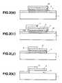
- Fig. 1is a schematic view of a first micro-structure
- Fig. 2(A)-(K)are views illustrating stages in a process of producing the microstructure of Fig. 1.
- 1is a first substrate
- 2is a beam member
- 3is a supporting structure.
- the member 2is suspended above the first substrate 1, over an airspace 4, by the supporting structure 3, and the beam 2 is attached to the supporting structure 3 at its surface 5 which is further from the substrate 1.
- the first substrate 1 and a second substrate 6are provided, and then a first sacrificial layer 7 is formed on the first substrate 1 (Fig. 1(A)).
- Photo-resistis coated on the second substrate 6 to form a photoresist layer, after which the photo-resist layer is exposed to radiation and is developed to form a patterned photo-resist layer 8 (Fig. 2(B)).
- the second substrate 6is then etched using the patterned photo-resist layer as a mask to produce a patterned prominence 9 which is to form the beam member 2 (Fig.2(C)).
- the first substrate 1 having the first sacrificial layer 7is then adhered to the second substrate 6 with the patterned prominence 9 in contact with the first sacrificial layer 7 (Fig.2(D)).
- the second substrate 6is then etched down to the patterned prominence 9 to produce the beam-shaped member 2 (Fig. 2(E),(F)), after which the first sacrificial layer 7 is etched using the member 2 as a mask (Fig.2(G)).
- a layer 10 for the supporting structure 3is formed on the member 2 and on the exposed adjacent surfaces of the first sacrificial layer 7 and the first substrate 1 (Fig. 2(H)).
- the first sacrificial layer 7is then removed to complete the manufacture of the microstructure shown in Fig. 1.
- the first sacrificial layer 7acts as an adhesive layer, and for this purpose may comprise resin.
- the first sacrificial layercan be formed by usual methods, such as by applying a coating solution in which resin is dissolved in an organic solvent, by spin coating, spray coating, dip coating etc., or by forming a film by the Langmuir-Blodgett method.
- a resin film having a flat surfacecan be obtained by these methods, even if the substrate has a rough surface, therefore in the step for adhering the first substrate to the second substrate, face-adhering can be effected without depending on surface roughness of the substrate.
- Preferred resin materialsinclude photo-resists. These should not contain impurities, such as sodium ions, if the first substrate is a silicon substrate including integrated circuit components.
- photo-resists containing a rubber having both good adhesive strength and good mechanical strengthare preferably used.
- cyclized rubberssuch as disclosed in "Bisaikako & Rejisuto (Fine Processing and Resist)" written by Saburo Nonogaki, edited by Kobunsi Gakkai (Society of Polymer), published by Kyoritsu Shuppan, 1991, pages 11-12 are preferably used, and as the photoresists containing rubber, OMR-83 (manufactured by Tokyo Oka Kogyo K.K.) is preferably used.
- a mono-molecular laminated filmthat is a Langmuir-Blodgett (LB) film consisting of molecules with hydrophobic group and a hydrophilic group, is laminated on the first substrate 1, at least one layer or more, to form the sacrificial layer 7.
- LBLangmuir-Blodgett
- the hydrophobic groups of each monomolecular filmare adjacent and the hydrophilic group of each mono-molecular film are adjacent.
- the thickness of the sacrificial layer 7can be regulated to nanometre precision, thus the air space 4 between the beam member 2 and the first substrate 1 can be regulated to the same nanometre precision.
- the process as described belowis preferred, that is, pressing together the first substrate 1 with the sacrificial layer 7 and the second substrate 6, and then heating the sacrificial layer 7 to evaporate solvent in the sacrificial layer 7 to cure the resin therein and to increase adhesive strength.
- at least one of the first substrate 1 and the second substrate 6may be provided with a groove to allow solvent vapour to escape via the groove. Where the first substrate 1 and the second substrate 6 are conductive, it is possible to adhere the first and second substrates 1,6 while applying voltage between these substrates 1,6 to generate an electrostatic field.
- the substrates 1,6can be adhered by the process as described below, that is a LB film formed on the first substrate 1 (or the second substrate 6) is brought into contact with the surface of the second substrate 6 (or the first substrate 1), and then a voltage is applied between the substrates 1,6 to generate an electrostatic field to adhere them to each other.
- the LB filmspreferably are formed so that the hydrophilic group of one LB film comes into contact with hydrophilic group of the other LB film, or the hydrophobic group of one LB film comes into contact with the hydrophobic group of the other LB film.
- the surface of the substrateis chosen to be hydrophilic, and when the surface of the LB film is hydrophobic, the surface of the substrate is chosen to be hydrophobic.
- the temperature of the LB filmis maintained below its decomposition temperature, and a voltage is applied between the first and the second substrates 1,6 the substrates 1,6 can be adhered firmly.
- the first substrate 1can be adhered to a patterned prominence for the microstructure by a LB film.
- the resin layercan be cured at a relatively low temperature so that damage to the substrate 1 due to difference of thermal expansion coefficients between the first and second substrates 1,6 can be avoided.
- the choice of materials for the substrates 1,6is not restricted in relation to thermal expansion coefficients.
- a second substrate 6 or a second substrate 6 having a layer for the structurealso may be processed.
- Examples of the second substrate 6 having a layer for the structuremay include a substrate 6 on which this layer is formed directly or a substrate 6 on which the layer is formed over said sacrificial layer for releasing the substrate 6 from the layer.
- the second substrate 6is processed by a suitable method, such as by photolithography, to form a patterned structure, after which the second substrate 6 is attached to the first substrate 1 by the first sacrificial layer 7 with the patterned surface of the second substrate 6 facing the first substrate 1.
- the second substrate 6is then etched down to the patterned prominence 9 from the opposite surface to the patterned prominence 9 (i.e. the back surface) by wet etching with a suitable etchant for the second substrate 6, or by dry etching with a reactive gas, or the back surface of the second substrate 6 is abraded and lapped to form the patterned thin film structure 2.
- examples of etchants for wet etchinginclude alkali aqueous solutions, such as a solution of potassium hydroxide (KOH), a solution of tetramethyl-ammonium hydroxide (TMAH), etc., or mixed aqueous solutions of hydrogen fluoride and nitric acid, and examples of reactive gases for dry etching include plasma gases of CF 4 , SF 6 , NF 3 etc.
- alkali aqueous solutionssuch as a solution of potassium hydroxide (KOH), a solution of tetramethyl-ammonium hydroxide (TMAH), etc.
- reactive gases for dry etchinginclude plasma gases of CF 4 , SF 6 , NF 3 etc.
- the microstructure obtainedis not warped.
- examples of the second substrates 6include a laminated substrate which a glass substrate is bonded anodically to a metal layer as the second sacrificial layer formed on the layer for the structure, a substrate having an internal layer, such as SOI substrate which has silicon oxide film as the second sacrificial layer and silicon layer as the layer for the structure, SIMOX substrate etc., a substrate on which the second sacrificial layer and the layer for the structure is formed directly.
- Examples for the material of the second sacrificial layerare selected from materials which are eroded by an etchant which does not erode the layer for the structure 2.
- the second sacrificial layer and/or the layer for the structuremay be produced by a film forming method, such as vacuum evaporation, liquid coating and chemical vapour deposition and so on.
- the glass substratepreferably may contain mobile ions of alkali metal, such as sodium ions,lithium ions, etc.
- the metal filmpreferably may be of metal which can be bonded anodically, such as Al, Ti, Ni and so on, or of an alloy which contains a combination of these metals.
- Anodic bonding, such as may be used herein,is described, for example in U.S. Patent 3,397,278.
- the layer usedmay be chosen from various materials, such as insulator semiconductor, or metal material.
- the second substratecan be removed from the layer by wet etching using an etchant suitable for the material of the second substrate, dry etching by a reactive gas, or abrasion.
- the second substratecan be removed from the layer by removing the second sacrificial layer to transfer the layer for the structure on the first sacrificial layer which had been formed on the first substrate.
- the first sacrificial layermay comprise one layer or two or more layers, and in case of forming the first sacrificial layer comprising two or more layers, each layer may be cured before forming the other layer on the layer to avoid dissolution of the layer.
- the curingcan be practised by use of usual methods, such as baking, irradiation and so on.
- the curing temperaturemay be the temperature at which the resin in the photoresist becomes crosslinked and insoluble to developer.
- the part which is irradiatedis cured.
- organic solvent vapouris evaporated from the photoresist so that it is preferable to provide a groove on the first substrate and/or second substrate to allow the vapour to escape, as described above.
- the supporting structure 3connects the first substrate and the layer for the structure, and is formed before removing the first sacrificial layer to provide support for the layer at the upper surface of the layer.
- the layercan be connected with the first substrate electrically.
- the first sacrificial layercan be removed by usual methods, such as immersion in a solvent for dissolving resin, dry etching by ashing with oxygen plasma etc. Further, in case of using LB film as the first sacrificial layer, the first sacrificial layer can be removed by heating to decompose the LB film. Examples of heating the LB film may include irradiating by laser beam, such as from a CO 2 laser.
- the choices of the first substrate material, the second substrate material and the material for the layer for the structureare not restricted.
- electrodescan be provided on the structure. Provided the first sacrificial layer is removed by using solvent, by ashing, by heating etc., electrodes are not etched.
- stickingcan be avoided by removing the first sacrificial layer and the second sacrificial layer by dry etching process or heating.
- microstructuremay include: cantilevers for microscopes which detect tunnelling electric current, Van der Waals' force, magnetic force or electrostatic force etc., such as atomic force microscopes (AFM); scanning tunnelling microscopes (STM); and electric circuits having air bridge structure, etc.
- cantilevers for microscopes which detect tunnelling electric currentVan der Waals' force, magnetic force or electrostatic force etc.
- AFMatomic force microscopes
- STMscanning tunnelling microscopes
- electric circuits having air bridge structureetc.
- an electrostatic actuatorcomprising a substrate, fixed electrode and first plate electrode which are formed on the substrate, a beam provided on the first plate electrode over an air space by a supporting structure comprising a metal film and a second plate electrode formed on the beam, wherein the electrode is connected electrically with the fixed electrode by the supporting structure, and the beam is supported by the supporting structure at the upper surface of the beam, and the beam is movable by applying voltage between the first plate electrode and the movable electrode can be obtained.
- a microstructure shown in Figure 1was prepared according to a process as shown in Figure 2.
- a monocrystalline silicon substratewas provided as a second substrate 6.
- a layer of photoresistwas coated on this silicon substrate 6.
- the photoresist layerwas then exposed and developed to produce the patterned photoresist layer 8 whose pattern corresponds to the pattern of the beam-shaped member 2.
- the silicon substrate 6was etched by reactive ion etching with a mixture of SF 6 and CCl 2 F 2 using the patterned photoresist layer 8 as a mask to produce a beam patterned prominence 9.
- the patterned photoresist layer 8was then removed (Fig. 2(C)).
- the height of the beam patterned prominence 9was 5 ⁇ m.
- a glass substrate(trade name: # 7059; manufactured by Corning) was provided as the first substrate 1.
- PMMAPolymethylmethacrylate
- MEKmethylethylketone
- the second substrate 6 shown in figure 2(C)was adhered to the surface of the first substrate 1 by the first sacrificial layer 7 by applying pressure to the back surface of each substrate 1,6.
- the first sacrificial layer 7was then cured by heating at 150°C. and the thickness of the cured first sacrificial layer 7 was 2 ⁇ m.
- the silicon substrate 6was then etched with a 30 wt% KOH aqueous solution heated at 100°C. to form a thin silicon membrane 12 as shown in Figure 2(E), after which the silicon thin film was removed by reactive ion etching with SF 6 gas to produce the beam-shaped member 2 having 1 ⁇ m of thickness ( Figure 2(F)).
- the first sacrificial layer 7was then etched by reactive ion etching with oxygen using the beam-shaped member 2 as a mask ( Figure 2(G)).
- an aluminium layer 10was formed on the exposed surfaces of the first substrate 1, first sacrificial layer 7 and member 2 by sputtering.
- the thickness of the aluminium layer 10was 1 ⁇ m.
- a patterned photoresist layer 11was formed on the aluminium layer 10 ( Figure 2(I)).
- the aluminium layer 10was then etched by an etchant comprising acetic acid, phosphoric acid and nitric acid to produce the supporting structure 3 ( Figure 2(J)).
- the first sacrificial layer 7was removed by immersing the first substrate 1 into an organic solvent for removing PMMA (trade name: OMR Remover, manufactured by Tokyo Ouka Kogyo K.K.) to complete the microstructure comprising a 1 ⁇ m thickness silicon beam 2 supported by aluminium supporting structure 3, and having a 2 ⁇ m air space 4 between the beam 2 and the first substrate 1.
- PMMAtrade name: OMR Remover, manufactured by Tokyo Ouka Kogyo K.K.
- the bridge member 2was provided by a part 9 of the second substrate 6 made of crystalline silicon as shown in Figure 2(B). A patterned beam member which does not have internal stress therefore can be prepared easily.
- the second substrate 6was grooved so that vapour evaporated in the step of curing the first sacrificial layer 7 could escape. If a groove is not provided, bubbles can be trapped between the first sacrificial layer 7 and the second substrate 6. When a groove is provided, bubbles can be avoided.
- the material of the first substrate 1can be selected from materials whose thermal expansion coefficients are different from that of the second substrate 6.
- the first sacrificial layer 7serves not only as a spacer but also as an adhesive layer.
- aluminiumis used for the supporting structure 3 but insulator material, such as silicon dioxide etc., could be used instead to produce an insulated microstructure.
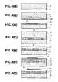
- a microstructure shown in Figure 3was prepared according to the process as shown in Figure 4.
- the beam member 2is provided with a second plate electrode 16 and is spaced above the insulating layer 13 by an air space 4. (Hereinafter this structure is called an "air bridge structure").
- the supporting structure 3is of an electrically conductive material, and the second plate electrode 16 is connected to the fixed electrode 15 electrically by the supporting structure 3.
- the microstructure of this examplecan be used as an electrostatic actuator.
- a silicon substratewas provided as the second substrate 6.
- a 1 ⁇ m thick silicon nitride layer 17was formed on the silicon substrate 6 by Low Pressure Chemical Vapour Deposition (LP-CFD) using a gas mixture of dichlorosilane (SiH 2 Cl 2 ) and ammonia (NH 3 ) at 850°C ( Figure 4(A)).
- LP-CFDLow Pressure Chemical Vapour Deposition
- a rubber type photoresist(trade name: OMR83 : manufactured by Tokyo Ouka Kyogo K.K.) was coated on the silicon nitride layer 17 by spin coating to form a first photoresist layer 7a ( Figure 4(B)).
- a silicon substrate 1 provided with an insulating layer 13, a first plate electrode 14 and a fixed electrode 15 (not shown in Figure 4)was prepared.
- the insulating layer 13was prepared by thermally grown oxidation of the silicon substrate 1 by an oxidising gas, and typically the thickness of this insulating layer 13 is 1 ⁇ m.
- the first plate electrode 14 and the fixed electrode 15were prepared by forming a 5 nm thickness Cr layer and a 20 nm thickness Au layer on the insulating layer 13 by electron beam deposition, and patterning by photolithography.
- the first substrate 1 and the second substrate 6were then heated at 50°C for 10 minutes to regulate the amount of solvent in the photoresist layers 7a,7b in order to avoid bubbles between the photoresist layers 7a,7b when the photoresist layer 7a was adhered to the photoresist layer 7b.
- the second substrate 6was then placed on the first substrate 1 with the photoresist layers 7a, 7b therebetween and 100 V of voltage was applied between the first substrate 1 and the second substrate 6 to adhere the substrates 1,6 by the photoresist layers 7a,7b, after which the photoresist layers 7a,7b were then heated at 120°C to cure the photoresist layers 7a,7b and produced a consolidated photoresist layer 7 (fig. 4(D)).
- the cured consolidated photoresist layer 7was 2 ⁇ m thick.
- the second substrate 6was removed by wet etching using 30 wt% of KOH aqueous solution to expose the silicon nitride layer 17 (figure 4(E)).
- silicon nitridewas not etched substantially since the etching speed of silicon nitride is much lower than that of silicon.
- a metal film 18consisting of Cr and Au sub-layers was formed on the silicon nitride layer 17 in the same manner as for forming the first plate electrode 14 and the fixed electrode 15, and a patterned photoresist layer 19 was formed by photolithography ( Figure 4(F)).
- the metal film 18was then etched by using the patterned photoresist layer 19 as a mask to form the second plate electrode 16, and then a patterned photoresist layer 20 whose pattern corresponded to the pattern of the beam member 2 was formed on the silicon nitride layer 17 ( Figure 4(G)).
- the silicon nitride layer 17was then etched by reactive ion etching using CF 4 gas with the patterned photoresist layer 20 as a mask. After this, the patterned photoresist layer 20 and exposed part of the photoresist layer 7 were ashed by reactive ion etching with oxygen gas and removed to complete production of the patterned beam member 2 ( Figure 4(H)).
- aluminiumwas deposited on the exposed surface of insulating layer 13 on the exposed surface of silicon nitride layer and on the second plate electrode 16 to form an aluminium layer 10, after which a patterned photoresist layer 11 was formed on the aluminium layer 10.
- the aluminium layer 10was then etched by reactive ion etching using a gas mixture of BCl 3 and Cl 2 to form the supporting structure 3.
- the patterned photoresist layer 11 and the patterned photoresist layer 7were etched with oxygen plasma and an air space formed between the beam member 2 and the substrate 1 ( Figure 4(L)).
- the concentration of the oxygenwas 50 ccm or more and pressure of the gas was 20 Pa or more to promote isotropic etching.
- a microstructurecomprising a 2 ⁇ m air-space 4 and a 1 ⁇ m-thick beam member 2 as shown in Figure 3 was prepared.
- a photoresist layer 7was used as a first sacrificial layer.
- Each electrodewas not etched and sticking, which would have happened if the sacrificial layer had been removed by wet etching, was avoided since dry etching was used.
- a silicon nitride layer formed on the second substratewas transferred onto the first substrate to form the beam member and a patterned plate electrode was formed on the beam member. This electrode was connected electrically to the fixed electrode formed on the first substrate by the supporting structure.
- the free-end of the beam membera cantilever portion, could be displaced toward the first substrate correspond to the torsional twisting of the torsion bar portion of the beam member by applying a voltage between the first and second plate electrodes.
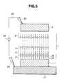
- FIG. 5is a schematic view illustrating the step of adhering the first substrate to the second substrate by this first sacrificial layer.
- 1is a silicon first substrate
- 6is a silicon second substrate
- 7is a LB layer formed by LB technique on the first substrate 1
- the LB layer 7consists of many LB film monomolecular sublayers 21
- the LB layer 7is of thickness 80 nm.
- 22is a hydrophobic group and 23 is a hydrophilic group, and the LB film sub-layers 21 are laminated alternately with hydrophilic groups 23 adjacent and with hydrophobic groups 22 adjacent, as shown.
- 24is a power supply to apply a voltage between the first substrate 1 and the second substrate 6, and it is connected to needle electrodes 25 by conductive wires 26.
- 27Is an electroconductive platen.
- stearic acidwas used for forming the LB layer 7 on the first substrate 1, and then the second substrate 6 having a patterned surface (not shown) was placed on the first substrate 1 with the LB layer 7 inbetween.
- the adhered substrates 1,6were processed in the same manner as in the process of Example 1 as shown in Figures 2(E) to 2(J) to form a microstructure comprising an aluminium supporting structure 3 and a silicon beam member having the same structure as that shown in Figure 2(J), except in using an LB layer instead of a PMMA layer as the first sacrificial layer 7.
- the microstructurewas then heated at 350°C for 1 hour to decompose and remove the LB layer 7, and a 80 nm air-space was formed between the first substrate 1 and the silicon beam member 2.
- a microstructure having an air-space which is regulated to nm precisioncan be prepared by using an LB layer as the first sacrificial layer.
- the LB layercan be removed by heating, so that sticking which can happen if the first sacrificial layer is removed by wet etching can be avoided.
- the LB layer 7is formed on the first substrate 1. However, it can be formed on the second substrate 6, or can comprise sub-layers formed on the first substrate 1 and the second substrate 6. Examples of removing the LB layer 7 may include irradiating by laser, such as CO 2 laser to decompose the LB layer 7.
- stearic acidwas used for forming the LB layer 7, but arachidic acid, ferroelectric LB film, such as diacetylene type, benzene derivatives type, and polyimide LB film also can be used to form the LB layer 7 of the example.
- Examples of the substrate 1may include glass, metal, glass substrate on which metal film has been formed, etc.
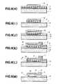
- a silicon substrate 28was prepared, and a 200 nm thick aluminium layer 29 was formed on the silicon substrate 28 as a second sacrificial layer by electron beam deposition ( Figure 6(A)).
- a glass substrate(trade name: No. 7740, mfd. by Corning) was prepared as the second substrate 6, after which the silicon substrate 28 having the aluminium layer 29 was bonded anodically to the glass substrate 6.
- 24is a power supply for applying voltage between the aluminium layer 29 and the glass substrate 6, and it is connected with needle electrodes 26 by connecting wires 26, and 27 is an electroconductive platen comprising a heating means (not shown).
- the second substrate 6was placed on the aluminium layer 29, after which 500 V of voltage was applied between the second substrate 6 and the aluminium layer 29 for 20 minutes at a platen temperature of 300°C to bond the second substrate 6 to the silicon substrate 28 (Figure 6(B)).
- the silicon substrate 28was then abraded down to a layer of 2 ⁇ m-thickness ( Figure 6(C)).
- a patterned photoresist layerwhose pattern corresponded to a beam pattern, was formed on the silicon layer 28, after which the silicon layer 28 was etched by reactive ion etching using CF 4 gas, after which the aluminium second sacrificial layer 29 was etched by reactive ion etching using a gas mixture of BCl 3 and Cl 2 to form the beam member 2 having a cantilever portion ( Figure 6(D)).
- a silicon first substrate having an insulating layer 13, a first plate electrode 14, and a fixed electrode 15was prepared.
- the insulating layer 13had been formed in the same manner as in Example 2.
- the first plate electrode 14 and the fixed electrode 15had been formed as follows: first of all, a 5 nm Cr layer and a 200 nm Au layer were formed on the insulating layer 13 by electron beam deposition, after which a patterned photoresist layer was formed on the Au layer, after which the Au layer was etched with an etchant comprising iodine and potassium iodide, and the Cr layer was etched with an etchant comprising cerium ammonium nitrate and perchloric acid.
- a rubber-type photoresist(trade name: OMR 83; mfd. by Tokyo Ouka Kogyo) was coated on the surface of the first substrate having the fixed elecrode 15 and the first plate electrode 14 to form the first sacrificial layer 7 ( Figure 6(E)).
- the second substrate 6 having the beam member 2was then pressed onto the first sacrificial layer 7, after which these substrates 1,6 were heated at 150°C to evaporate the organic solvent in the photoresist layer 7 and to cure it to adhere the second substrate 6 to the first substrate 1.
- the cured photoresist layer 7had 2 ⁇ m of thickness.
- the aluminium second sacrificial layer 29was then removed at 80°C by an etchant comprising phosphoric acid, nitric acid and acetic acid to release the second substrate 6 ( Figure 6(G)).
- the beam member 2was thus transferred to the first sacrificial layer 7.
- the first sacrificial layer 7 and the first substrate 1were not etched by the aluminium etchant.
- the second plate electrode 16was formed on the beam member 2 in the same manner as that for the fixed electrode 15 and the first plate electrode 14 ( Figure 6(H)).
- the first sacrificial layer 7was then etched by reactive ion etching using oxygen-gas, and using the pattern of the beam as a mask ( Figure 6(I)).
- aluminiumwas deposited on the insulating layer 13, the beam member 2 and the second plate electrode 16 to form 2 ⁇ m of aluminium layer 10 (Figure 6(J)), after which a patterned photoresist layer 11, whose pattern corresponds to the pattern of the supporting means 3, was formed on the aluminium layer 10 ( Figure 6(K)).
- the aluminium layer 10was then etched by reactive ion etching using a gas mixture of BCl 3 and Cl 2 to form the supporting means 3.
- the photoresist layer 11 and the first sacrificial layer 7were then removed by etching with oxygen plasma to form a microstructure having a space 4 ( Figure 6(M)).
- a microstructure having a 2 ⁇ m air space 4 and a 2 ⁇ m-thickness silicon beam member 2 having a cantilever portion supported by an aluminium supporting structure 3was prepared, and in addition each electrode 14, 15, 16 was not etched and sticking was avoided by using reactive ion etching.
- a beam member 2 which does not have internal stress and which is not bentcan be formed from processing the substrate 28 made of crystalline silicon, and the beam member can be connected electrically with the fixed electrode 15 formed on the first substrate 1 by the supporting structure 3.
- Examples of the substrate 1may include silicon, glass, GaAs,metal, a glass substrate on which a metal film has been formed, etc.
- a voltage of 100 Vcan be applied between the beam member 2 and the first substrate 1 to generate electrostatic force, instead of applying pressure.
- an SOI substrate having a 2 ⁇ m-thickness silicon layeris prepared, after which the aluminium layer 29 is formed on the silicon layer.
- the silicon layeris bonded anodically to the second substrate 6.
- the SOI substratewas etched with 30 wt% of KOH aqueous solution to remove the silicon base substrate of the SOI substrate.
- the silicon dioxide layeracts as an etch stop layer so that once the silicon substrate is removed, the etching is stopped.
- the silicon dioxide layeris removed by hydrogen fluoride aqueous solution to produce a laminated second substrate comprising a 2 ⁇ m-thick silicon layer 28 on the second sacrificial layer 29 and the second substrate, the same structure as shown in Figure 6(c). In this case, the thickness of the layer for the beam member 2 can be guaranteed.
- the SOI substratecan be used directly as a laminated second substrate as shown in Figure 6(C), in which case the buried thermally grown silicon dioxide serves as the second sacrificial layer instead of aluminium.
- the silicon layer of the SOI substrateis etched to form a pattern in the same manner as that shown in Figure 6(D), after which the patterned silicon film 2 is adhered to the first substrate 1 shown in Figure 6(E).
- the buried silicon dioxideis then removed with hydrogen fluoride to transfer the patterned silicon layer onto the first sacrificial layer 7 as shown in Figure 6(G).
- aluminium filmwas used as the second sacrificial layer, but other metal which can be bonded anodically, such as Ti, Cr, Ni etc., and a selective etchant chosen which does not erode the first sacrificial layer 7 and the beam member 2.
- a first sacrificial layer 7 of resincan serve as an adhesive layer, in which case the layer 28 should be grooved so that solvent vapour evaporated can escape in the step of curing the first sacrificial layer 7 ( Figure 6(F)).
- a silicon substrate 30was provided having a 1 ⁇ m-thick thermally grown silicon dioxide layer 31 which is to form the beam member 2.
- a 200 nm Cu layer and a 10 nm Al layerwere formed on the silicon dioxide layer 31 by sputtering to form the second sacrificial layer 29 ( Figure 8(A)).
- the second sacrificial layer 29was then bonded anodically to a second substrate 6 of glass (trade name: No. 7740; mfd. by Corning) in the same manner as that in Example 4 ( Figure 8(B)).
- a second substrate 6 of glasstrade name: No. 7740; mfd. by Corning
- Figure 8(C)the aluminium in the second sacrificial layer 29 was dispersed into the copper layer to form an alloy of aluminium and copper at the interface of the Al layer and the Cu layer.
- the silicon substrate 30was then removed by dry etching using SF 6 gas (Figure 8(C)).
- This etching stepwas selective and therefore the silicon oxide layer 31 remained on the second substrate 6.
- the first substrate 1a glass substrate (trade name: No. 7059; mfd. by Corning) was prepared, and the first plate electrode 14 and fixed electrode 15 (not shown in Figure 8) were formed on the first substrate 1 in the same manner as in Example 4. Next, a solution in which PMMA had been dissolved into MEK was coated on the electrode surface of the first substrate 1 to form the first sacrificial layer 7 ( Figure 8(D)). The first substrate 1 was then heated at 50°C for 10 minutes to regulate the amount of the solvent in the first sacrificial layer 7 to prevent bubbles forming at the adhesive interface when the first substrate 1 is later adhered to the second substrate 6.
- the pressurewas regulated in order that the silicon dioxide layer 31 was adhered adequately to the first sacrificial layer 7.
- the first layer 7was then cured at 150°C.
- the cured first sacrificial layer 7had a 2 ⁇ m thickness.
- the second sacrificial layer 29was then removed by an etchant selective for copper comprising FeCl 3 , to release the second substrate 6, and to transfer the silicon dioxide film 31 onto the first sacrificial layer 7 ( Figure 8(F)).
- a patterned photoresist layerwas formed on the silicon dioxide layer 31, and the silicon dioxide layer 31 was then etched with hydrogen fluoride using the patterned photoresist layer as a mask to form the beam member 2; after which the patterned photoresist was removed by reactive ion etching with oxygen gas, and in this etching step for the photoresist, the first sacrificial layer 7 was also etched to form a patterned first sacrificial layer, whose pattern was the same as the pattern of the bridge member 2 ( Figure 8 (G)).
- the second plate electrode 16was formed on the beam member 2 in the same manner as in Example 4 ( Figure 8(H), (I)), after which a 2 ⁇ m-thick aluminium layer 10 was formed ( Figure 8(J)).
- a patterned photoresist layer 11was formed and the aluminium layer 10 was etched to form the supporting structure 3 in the same manner as in Example 4 ( Figure 8(K), (L)), after which the patterned photoresist layer 11 and the first sacrificial layer 7 of PMMA were removed by immersion in an organic solvent for removing the photoresist (trade name: OMR Remover - 502; mfd. by Tokyo Ouka Kogyo K.K.) to prepare a microstructure having a 2 ⁇ m air space 4 and a 1 ⁇ m-thick silicon dioxide beam member 2 supported by an aluminium supporting structure 3.
- the aluminium supporting structure 3was not etched.
- the microstructure prepared in this examplehad the same structure as the electrostatic actuator shown in Figure 3 except for using a glass substrate 1.
- the thermal expansion coefficient of glassis one order of magnitude larger than that of the thermally grown silicon oxide, but nevertheless a microstructure with a structure made of insulating material is formed on a substrate whose thermal expansion coefficient is different from that of the insulating material can be prepared.
- the first substrate 1a glass substrate was used, but other insulating material, such as quartz, Al 2 0 3 , Mg0, Zr0 2 etc., or semiconductor material, such as Si, GaAs, InP etc. or metallic materials can be used.
- insulating materialsuch as quartz, Al 2 0 3 , Mg0, Zr0 2 etc.
- semiconductor materialsuch as Si, GaAs, InP etc. or metallic materials can be used.
- silicon dioxidewas used, but other insulating material, which can be processed as film, such as silicon nitride, Al 2 0 3 , APN etc. can be used.
- the layer 31 for the beam member 2may be formed after forming the second sacrificial layer 29 on the second substrate 6.
- examples of the second sacrificial layer in Example 5may include a layer which can be bonded anodically to the second substrate 6, such as an alloy layer of Cu and Al formed by sputtering.
- Example 5the second sacrificial layer 29 was removed by wet etching, but it can be removed by dry etching with oxygen gas.
- FIG. 9Another example of a process for producing a microstructure as shown in Figure 1 will be explained with reference to Figure 9.
- a substrate of crystalline siliconwas prepared as a second substrate 6, and the second substrate 6 was etched to form a patterned prominence 9 of the beam 2 in the same manner as in Example 1 ( Figure 9(A), (B)).
- the height of the prominence 9was 5 ⁇ m.
- a glass substrate(trade name: No. 7059; mfd. by Corning) was prepared as a first substrate 1.
- the polyimide layer 7c and the PMMA layer 7dconstituted a first sacrificial layer 7.
- the second substrate 6was placed on the first substrate 1 with the prominence 9 in contact with the PMMA layer 7d, after which the substrates 1,6 were heated at 150°C to cure the PMMA layer 7d, and to adhere the second substrate 6 to the first substrate 1 (Figure 9(D)).
- the first substrate 1was then etched to form the beam member 2 on the PMMA layer 7d in the same manner as in Example 1, then using the beam member 2 as a mask, part of the first sacrificial layer 7 was removed by reactive ion etching using oxygen gas (Figure 9(G)).
- the aluminium supporting structure 3was formed in the same manner as in Example 1 ( Figure 9(H) to 9(J)).
- the patterned photoresist layer 11 and the first sacrificial layer 7were removed to prepare a microstructure comprising a silicon beam member 2 on the substrate 1 and having an air-space 4 between the beam member 2 and the substrate 1 and the beam member 2 was suspended by the aluminium supporting structure 3.
- stickingcould be avoided by using dry etching with oxygen plasma.
- a beam member which does not have internal stress, and which is not bentcan be prepared because of forming the beam member by processing crystalline silicon crystal to a thin layer.
- the silicon substrate 6was provided with a groove beside the prominence 9 so that solvent vapour, evaporated in the step of curing the PMMA layer 7c, could escape.
- the amount of the solvent in the resin layermay be regulated to avoid bubbles being trapped at the adhesive interface.
- the amount of the solventcan be regulated by heating the resin layer at a low temperature at which the resin layer is not cured. It is possible to avoid bubbles in the 0.5 ⁇ m thickness of PMMA layer by heating at 50°C for 10 minutes.
- a resin layer(PMMA layer) was used as an adhesive layer so that the adhesive layer could be cured at 150°C.
- PMMA layera resin layer whose thermal expansion coefficient is different from that of the first substrate.
- Examples of the first substrate 1may include an insulator, such as quartz, Al 2 0 3 , Mg0, Zr0 2 etc., a semiconductor, such as Si, GaAs, InP, or metallic materials.
- an insulatorsuch as quartz, Al 2 0 3 , Mg0, Zr0 2 etc.
- a semiconductorsuch as Si, GaAs, InP, or metallic materials.
- the prominence 9is embedded into the PMMA layer 7d, but it is not embedded into the polyimide layer 7c as shown in Figure 9(D) so the polyimide layer acts as a layer for regulating the thickness of the air-space 4.
- the air spacecan be regulated with good accuracy even if the substrate is warped and/or pressure is not applied uniformly when the second substrate 6 is adhered to the first substrate 1.
- First of all 5 cm diameter glass substratewas provided as a first substrate 1.
- This glass substrate 1was provided with a 200 nm-thick Cr layer on its surface, and it was warped due to the internal stress of the Cr layer.
- a 2 ⁇ m-thick polyimide layer 7c and a 0.5 ⁇ m-thick PMMA layer 7dwere formed on the Cr layer in the same manner as in Example 6 to form a first sacrificial layer 7.
- a 5 cm diameter silicon wafer substratewas provided as a second substrate 6, and the second substrate 6 was provided with four beam members each produced in the same manner as in Example 6.
- Each patternhad a 100 ⁇ m-width, a 20 mm-length and were separated at a 10 mm-pitch.
- the first substrate 1having four silicon beams on the PMMA layer 7d in the same manner as in Example 6, and as disclosed in Figure 9(D) to (G).
- the silicon beams 2were then etched away, and the thickness of the first sacrificial layer 7 was measured. The thickness was within the range of 2-2.2 ⁇ m.
- first substrate 1 having four silicon beams 2was prepared in the same manner as described above except in forming a 2.5 ⁇ m-thickness PMMA layer 7 instead of forming a 2 ⁇ m-thickness of polyimide layer 7c and 0.5 ⁇ m-thickness of PMMA layer 7d.
- the beams 2were etched away, and the PMMA layer thickness was measured. The thickness was in the range from 1.5 ⁇ m to 2.4 ⁇ m. This confirms that better accuracy is achieved by dividing the functions as aforesaid.
- a microstructure as shown in Figure 3was prepared in the same manner as in Example 4 ( Figure 6) except in using a first sacrificial layer 7 consisting of two photoresist layers 7c,7d instead of a single photoresist layer.
- the first sacrificial layer 7 in this examplewas prepared as follows: a rubber type photoresist (trade name: OMR-83; mfd. by Tokyo Ouka Kogyo K.K.) was coated on the surface of the first substrate 1 including the fixed electrode 15 and the first plate electrode 14 to form a first photoresist layer 7c, after which the first photoresist layer 7c was heated at 80°C for 20 minutes to evaporate solvent in the photoresist layer, after which ultraviolet radiation was irradiated to the photoresist layer. The photoresist layer 7c was then heated at 150°C for 1 hour to cure it.
- a rubber type photoresist(trade name: OMR-83; mfd. by Tokyo Ouka Kogyo K.K.) was coated on the surface of the first substrate 1 including the fixed electrode 15 and the first plate electrode 14 to form a first photoresist layer 7c, after which the first photoresist layer 7c was heated at 80°C for 20 minutes to evaporate solvent in the photo
- the same photoresistwas coated on the first photoresist layer 7c to form 0.4 mm-thickness of a second photoresist layer 7d.
- the second photoresist layer 7dwas cured when the second substrate 6 was adhered to the first substrate 1.
- the patterned part to form the beam member 2is embedded in the second photo-resist layer 7d, but it is not embedded in the first photoresist layer 7c as disclosed in Figure 10(F) so the first photoresist layer 7c works as a layer for regulating the air-space 4.
- the spacecan be regulated with a good accuracy even if the substrate 1 is warped and/or pressure is not applied uniformly when the second substrate 6 is adhered to the first substrate 1.
Landscapes
- Engineering & Computer Science (AREA)
- Manufacturing & Machinery (AREA)
- Microelectronics & Electronic Packaging (AREA)
- Micromachines (AREA)
Description
- The present invention relates to a process ofproducing micro-structure.
- In particular it concerns a microstructure of thetype in which a beam is suspended over the surface of asubstrate by a support. There is an air-gap between thebeam and the substrate and no part of the beam isdirectly supported from below. An example of such amicrostructure is disclosed in Japanese PatentApplication JP-A-5116757 and Patent Abstracts of Japan,Vol.17, No. 486 (M-1473) of 3 September 1993.
- In recent years, micro-machines having small movableparts have been investigated. In particular, in the caseof making microstructures by using technologies forsemiconductor integrated circuits, such as those whichinclude photolithographic processing, micro-parts can bereproduced accurately. Thereby, the parts can be arrayedeasily on a substrate and the parts can be produced atlow cost. The parts can respond quicker than partsproduced by prior techniques because of their reducedsize.
- Three typical processes of producing a micro-structureon a substrate are described below.
- One is a process for producing a micro-motor (M.Mehregany et al, "Operation of micro fabricated harmonicand ordinary side-drive motors" - Proceedings IEEE MicroElectro-Mechanical Systems Workshop 1990, pp. 1-8) or alinear microactuator (P. Chenung et al, "Modelling andposition-detection of a polysilicon linear microactuator",Micro mechanical Sensors, Actuators andSystems ASME 1991, DS C-Vol.32, pp. 269-278).
- This first process comprises: forming a silicondioxide layer and a polysilicon layer on a siliconsubstrate in this order, or providing a SOI (silicon oninsulator) substrate;
- patterning the silicon layer or the polysiliconlayer to form a patterned structure; and
- removing the silicon dioxide layer by an aqueoussolution of hydrogen fluoride to produce themicrostructure. The silicon dioxide layer is used,therefore, as a sacrificial layer. (See "SOI (SIMOX) asa substrate for surface micromachining of singlecrystalline silicon sensors and actuators". The 7thInternational Conference on Solid State Sensors andActuators, Transducers 93, June 7-10, 1993, pp. 233-236).
- According to this first process, however, it isnecessary to use for the micro-structure, materials whichare not eroded by hydrogen fluoride, and it is notpossible to incorporate an electrode of erodablematerial, such as an aluminium electrode in the micro-structure.
- Furthermore, if polysilicon is adopted as the micro-structurematerial, it is necessary to regulate theinternal stress of polysilicon film in order to preventa bending of the substrate.
- Furthermore, in the case of using an SOI substrate,buried silicon dioxide is removed. If the removal of this oxide is not carefully controlled, over-etching willoccur. It is difficult therefore to maintain contactbetween the microstructure and the substrate. Also, ifaluminium or other metal is deposited after removal ofthe buried silicon oxide, it is not easy to form acontinuous electrode structure due to overhang of themicrostructure.
- The second process is a process for producing aspatial light modulator device provided with an aluminiummicro-mirror. This is described in Japanese Patent Laid-OpenApplication No. 2-8812. This process comprisescoating a photo-resist sacrificial layer on a substrate,then forming an aluminium layer on this sacrificiallayer, patterning the aluminium layer, and removing thesacrificial layer by oxygen plasma etching to producean aluminium film micro-structure.
- The micro-structure can be produced on various kindsof substrate and this does not depend on surfaceroughness of the substrate.
- In addition, since the sacrificial layer is removedby dry etching, here a oxygen plasma etching process,sticking between the substrate and the micro-structure,which can happen when removing the sacrificial layer bya wet etching process, is avoided. However, since it isnecessary to deposit the film for the micro-structure ata low temperature to avoid damage to the sacrificiallayer, the choice of microstructure material is severely restricted. Furthermore, it is necessary to regulate theinternal stress of the film for the microstructure toprevent the microstructure from bending.
- The third process is a process in which the patternfor the microstructure is formed on an Si substrate,after which a part of the pattern is bonded anodicallyto a glass substrate, after which the bonded Si substrateis etched from its back surface until the pattern is lefton the glass substrate.
- A linear actuator comprising bulk Si film (Y.Gianchandani et al, "Micron-Sized, High Aspect Ratio BulkSilicon Micromechanical Systems Devices", ProceedingsIEEE Electro Mechanical Workshop 1992, pages 208-213),or a cantilever comprising silicon nitride for an AtomicForce Microscope (AFM) may be produced by this process(U.S. Patent 5,221,415).
- In this process, it is not necessary to use asacrificial layer so that micro-structures made of amaterial which does not have resistance to hydrogenfluoride can be produced.
- However, the microstructure materials are limitedto those which can be bonded anodically to glass, suchas Si, Al, Ti, Ni, which are electroconductive and whichcan be oxidised, or silicon dioxide film or siliconnitride film coated on a substrate.
- Furthermore, when bonding is made anodically atemperature of 300°C or more is usual and it is necessary therefore to use a glass having the same thermalexpansion coefficient as that of the Si substrate toavoid damage to the substrate by heat stress. The choiceof glass is limited to pyrex glass (trade name # 7740;manufactured by Corning) or the like.
- Where an electrode is already provided on thesubstrate, it is then difficult to produce an electrodeon the microstructure.
- In addition, it is necessary to use a glass whichcontains mobile ions as the material of the substrate,such as soda glass, Pyrex and crystallised glass.Consequently, this process is inapplicable to substratesincorporating integrated circuit components.
- Furthermore, in the case of bonding the electro-conductivematerial to the glass anodically, it isnecessary for the glass and the electro-conductivematerial to have a surface roughness of 50 nm or less.
- In US Patent 5,221,415, silicon nitride is bondedanodically to glass at 475°C. Consequently, electrodeshave to be formed by vacuum evaporation on the wholesurface of the substrate after producing themicrostructure. It is difficult, however, to form apatterned electrode on a beam structure such as acantilever.
- The present invention is intended as a solution tothe problems aforesaid.
- According to the present invention, there isprovided a process of producing a microstructure havinga substrate, a beam member, and a supporting means,wherein the beam member is suspended over the surface ofthe substrate by said supporting means and is separatedfrom said surface by an air-space, which processcomprises performing in the following order steps of:
- (a) providing a first substrate having a firstsacrificial layer over its surface and a beammember on said first sacrificial layer;
- (b) removing that part of said first sacrificiallayer which is not sandwiched between saidbeam member and said substrate;
- (c) forming supporting means on said substrateand over said beam member with the insidesurface of said supporting means attached tothe surface of said first substrate and tothat surface of said beam member which isfurther from the surface of said firstsubstrate; and
- (d) removing the remainder part of said firstsacrificial layer to leave said beam memberseparated from the surface of said firstsubstrate by an air-space with no part thereofdirectly supported from below.
- It is mentioned that European Patent Application EP-A-0417523describes the manufacture of a microstructure by a process of forming a spacer layer, a first metallayer and a second metal layer, in that order, on thesurface of a silicon substrate. The second metal layeris etched leaving a central portion spaced from asurrounding peripheral part of the second metal layer.The same pattern is formed thereafter in the first metallayer except for a part that is left to support thecentral portion from below. The spacer layer is thenetched leaving a peripheral part supporting the patternedfirst and second layers of metal. At the periphery apart of the first and second layers of metal overhangfrom the spacer layer and are separated from thesubstrate by an air-gap. The peripheral parts of thefirst and second metal layers are supported from belowby the peripheral part of the spacer layer.
- Other aspects of the invention will be apparent fromthe description given below and from the appended claims.
- In the accompanying drawings:
- Figure 1 is a schematic view of a firstmicrostructure;
- Figures 2(A)-2(K) are sectional views forillustrating a first process for producing themicrostructure of Figure 1, taken on line A-A of Figure1;
- Figure 3 is a schematic view of an electrostaticactuator;
- Figures 4(A)-4(L) are sectional views, which aretaken on line B-B of Figure 3, for illustrating a firstprocess for producing the electrostatic actuator ofFigure 3;
- Figure 5 is a sectional view for explaining the useof an L-B film in a process for producing amicrostructure;
- Figures 6(A)-6(M) are sectional views forillustrating a second process for producing theelectrostatic actuator of Figure 3;
- Figure 7 is a schematic sectional view forexplaining a step of bonding a silicon substrate to asecond substrate anodically;
- Figures 8(A)-8(M) are sectional views forillustrating a third process for producing theelectrostatic actuator of Figure 3;
- Figures 9(A)-9(K) are sectional views forillustrating a second process for producing themicrostructure of Figure 1; and
- Figures 10(A)-10(M) are sectional views forillustrating a fourth process for producing theelectrostatic actuator of Figure 3.
- The present invention will be explained withreference to the drawings. The following description isgiven by way of example only.
- Fig. 1 is a schematic view of a first micro-structure, and Fig. 2(A)-(K) are views illustratingstages in a process of producing the microstructure ofFig. 1.
- Referring to figure 1, 1 is a first substrate, 2 isa beam member and 3 is a supporting structure. The
member 2 is suspended above thefirst substrate 1, over anairspace 4, by the supportingstructure 3, and thebeam 2 is attached to the supportingstructure 3 at itssurface 5 which is further from thesubstrate 1. - A process for producing the microstructure shown infigure 1 will now be explained with reference to figure2.
- First of all, the
first substrate 1 and asecondsubstrate 6 are provided, and then a firstsacrificiallayer 7 is formed on the first substrate 1 (Fig. 1(A)). - Photo-resist is coated on the
second substrate 6 toform a photoresist layer, after which the photo-resistlayer is exposed to radiation and is developed to forma patterned photo-resist layer 8 (Fig. 2(B)). - The
second substrate 6 is then etched using the patterned photo-resist layer as a mask to produce apatterned prominence 9 which is to form the beam member2 (Fig.2(C)). - The
first substrate 1 having the firstsacrificiallayer 7 is then adhered to thesecond substrate 6 withthepatterned prominence 9 in contact with the firstsacrificial layer 7 (Fig.2(D)). - The
second substrate 6 is then etched down to thepatternedprominence 9 to produce the beam-shaped member2 (Fig. 2(E),(F)), after which the firstsacrificiallayer 7 is etched using themember 2 as a mask(Fig.2(G)). - Next, a
layer 10 for the supportingstructure 3 isformed on themember 2 and on the exposed adjacentsurfaces of the firstsacrificial layer 7 and the firstsubstrate 1 (Fig. 2(H)). - Next, a patterned photo-resist
layer 11, whosepattern corresponds to the pattern of the supportingstructure 3, is formed on the layer 10 (Fig.2(I)) and thelayer 10 is etched using the patterned photo-resistlayer 11 as a mask to form the supporting structure 3(Fig.2(J)). The firstsacrificial layer 7 is thenremoved to complete the manufacture of the microstructureshown in Fig. 1. - In the process shown in Figure 2, the first
sacrificial layer 7 acts as an adhesive layer, and forthis purpose may comprise resin. The first sacrificial layer can be formed by usual methods, such as by applyinga coating solution in which resin is dissolved in anorganic solvent, by spin coating, spray coating, dipcoating etc., or by forming a film by the Langmuir-Blodgettmethod. A resin film having a flat surface canbe obtained by these methods, even if the substrate hasa rough surface, therefore in the step for adhering thefirst substrate to the second substrate, face-adheringcan be effected without depending on surface roughnessof the substrate. - Preferred resin materials include photo-resists.These should not contain impurities, such as sodium ions,if the first substrate is a silicon substrate includingintegrated circuit components. In particular, suchphoto-resists containing a rubber having both goodadhesive strength and good mechanical strength arepreferably used. As the rubber, cyclized rubbers suchas disclosed in "Bisaikako & Rejisuto (Fine Processingand Resist)" written by Saburo Nonogaki, edited byKobunsi Gakkai (Society of Polymer), published byKyoritsu Shuppan, 1991, pages 11-12 are preferably used,and as the photoresists containing rubber, OMR-83(manufactured by Tokyo Oka Kogyo K.K.) is preferablyused.
- In the case of using the Langmuir-Blodgett methodfor forming the first
sacrificial layer 7, a mono-molecularlaminated film, that is a Langmuir-Blodgett (LB) film consisting of molecules with hydrophobic groupand a hydrophilic group, is laminated on thefirstsubstrate 1, at least one layer or more, to form thesacrificial layer 7. In a multilayer film, thehydrophobic groups of each monomolecular film areadjacent and the hydrophilic group of each mono-molecularfilm are adjacent. - According to this method, the thickness of the
sacrificial layer 7 can be regulated to nanometreprecision, thus theair space 4 between thebeam member 2 and thefirst substrate 1 can be regulated to the samenanometre precision. - As the step for adhering the
first substrate 1 andthesecond substrate 6, the process as described belowis preferred, that is, pressing together thefirstsubstrate 1 with thesacrificial layer 7 and thesecondsubstrate 6, and then heating thesacrificial layer 7 toevaporate solvent in thesacrificial layer 7 to cure theresin therein and to increase adhesive strength. Inaddition, at least one of thefirst substrate 1 and thesecond substrate 6 may be provided with a groove to allowsolvent vapour to escape via the groove. Where thefirstsubstrate 1 and thesecond substrate 6 are conductive,it is possible to adhere the first andsecond substrates substrates - In case of adhering the first and the
second substrates substrates substrates - Further, in case of forming LB film on both thefirst and the
second substrates - Furthermore, in the case of forming the LB film onone only of the first and
second substrates second substrates substrates - In the process described above, the
first substrate 1 can be adhered to a patterned prominence for the microstructure by a LB film. In case of using a resinlayer for thesacrificial layer 7 as an adhesive layer,the resin layer can be cured at a relatively lowtemperature so that damage to thesubstrate 1 due todifference of thermal expansion coefficients between thefirst andsecond substrates substrates - In the steps for making the patterned thin filmstructure, such as the beam-shaped
member 2 in Figure 1,on thefirst substrate 1, asecond substrate 6 or asecond substrate 6 having a layer for the structure alsomay be processed. - Examples of the
second substrate 6 having a layerfor the structure may include asubstrate 6 on which thislayer is formed directly or asubstrate 6 on which thelayer is formed over said sacrificial layer for releasingthesubstrate 6 from the layer. - In case of forming the patterned thin film layerfrom the
second substrate 6, first of all, thesecondsubstrate 6 is processed by a suitable method, such asby photolithography, to form a patterned structure, afterwhich thesecond substrate 6 is attached to thefirstsubstrate 1 by the firstsacrificial layer 7 with thepatterned surface of thesecond substrate 6 facing thefirst substrate 1. Thesecond substrate 6 is then etcheddown to the patternedprominence 9 from the opposite surface to the patterned prominence 9 (i.e. the backsurface) by wet etching with a suitable etchant for thesecond substrate 6, or by dry etching with a reactivegas, or the back surface of thesecond substrate 6 isabraded and lapped to form the patternedthin filmstructure 2. - In case of using a silicon substrate as the
secondsubstrate 6, examples of etchants for wet etching includealkali aqueous solutions, such as a solution of potassiumhydroxide (KOH), a solution of tetramethyl-ammoniumhydroxide (TMAH), etc., or mixed aqueous solutions ofhydrogen fluoride and nitric acid, and examples ofreactive gases for dry etching include plasma gases ofCF4, SF6, NF3 etc. - When a substrate made of monocrystalline Si, GaAsetc. is used as the
second substrate 6, themicrostructure obtained is not warped. - In the case of forming the patterned
thin film layer 2 from thesecond substrate 6 having a layer for thestructure 2, examples of thesecond substrates 6 includea laminated substrate which a glass substrate is bondedanodically to a metal layer as the second sacrificiallayer formed on the layer for the structure, a substratehaving an internal layer, such as SOI substrate which hassilicon oxide film as the second sacrificial layer andsilicon layer as the layer for the structure, SIMOXsubstrate etc., a substrate on which the second sacrificial layer and the layer for the structure isformed directly. - Examples for the material of the second sacrificiallayer are selected from materials which are eroded by anetchant which does not erode the layer for the
structure 2. - The second sacrificial layer and/or the layer forthe structure may be produced by a film forming method,such as vacuum evaporation, liquid coating and chemicalvapour deposition and so on.
- In the case of using anodic bonding for bonding theglass substrate and the metal film as the secondsacrificial layer, the glass substrate preferably maycontain mobile ions of alkali metal, such as sodiumions,lithium ions, etc. The metal film preferably may beof metal which can be bonded anodically, such as Al, Ti,Ni and so on, or of an alloy which contains acombination of these metals. Anodic bonding, such as maybe used herein, is described, for example in U.S. Patent3,397,278.
- When the metal film as above is formed on the layerfor the structure, the layer used may be chosen fromvarious materials, such as insulator semiconductor, ormetal material.
- In the case of using the second substrate having alayer for the structure, it is necessary to remove thesecond substrate from the layer for the structure.
- The second substrate can be removed from the layerby wet etching using an etchant suitable for the materialof the second substrate, dry etching by a reactive gas,or abrasion.
- In the case of using a second substrate having asecond sacrificial layer, the second substrate can beremoved from the layer by removing the second sacrificiallayer to transfer the layer for the structure on thefirst sacrificial layer which had been formed on thefirst substrate.
- The first sacrificial layer may comprise one layeror two or more layers, and in case of forming the firstsacrificial layer comprising two or more layers, eachlayer may be cured before forming the other layer on thelayer to avoid dissolution of the layer.
- The curing can be practised by use of usual methods,such as baking, irradiation and so on.
- In the case of using photoresist for the firstsacrificial layer, the curing temperature may be thetemperature at which the resin in the photoresist becomescrosslinked and insoluble to developer.
- When negative type photoresist is used as thephotoresist, the part which is irradiated is cured. Inthis curing step organic solvent vapour is evaporatedfrom the photoresist so that it is preferable to providea groove on the first substrate and/or second substrateto allow the vapour to escape, as described above.
- The supporting
structure 3 connects the firstsubstrate and the layer for the structure, and is formedbefore removing the first sacrificial layer to providesupport for the layer at the upper surface of the layer. - In addition, in case of using aluminium for thesupporting structure, the layer can be connected withthe first substrate electrically.
- The first sacrificial layer can be removed by usualmethods, such as immersion in a solvent for dissolvingresin, dry etching by ashing with oxygen plasma etc.Further, in case of using LB film as the firstsacrificial layer, the first sacrificial layer can beremoved by heating to decompose the LB film. Examplesof heating the LB film may include irradiating by laserbeam, such as from a CO2 laser.
- When resin is used for the first sacrificial layer,it is possible to remove the first sacrificial layer bydry etching so that sticking, which can happen, when thefirst sacrificial layer is removed by wet etching, canbe avoided.
- As described above, in the process for producing themicrostructure the choices of the first substratematerial, the second substrate material and the materialfor the layer for the structure are not restricted. Inaddition, in the process for removing the firstsacrificial layer, electrodes can be provided on thestructure. Provided the first sacrificial layer is removed by using solvent, by ashing, by heating etc.,electrodes are not etched.
- Furthermore, sticking can be avoided by removing thefirst sacrificial layer and the second sacrificial layerby dry etching process or heating.
- Examples of the microstructure may include:cantilevers for microscopes which detect tunnellingelectric current, Van der Waals' force, magnetic forceor electrostatic force etc., such as atomic forcemicroscopes (AFM); scanning tunnelling microscopes(STM); and electric circuits having air bridge structure,etc.
- In particular, an electrostatic actuator comprisinga substrate, fixed electrode and first plate electrodewhich are formed on the substrate, a beam provided on thefirst plate electrode over an air space by a supportingstructure comprising a metal film and a second plateelectrode formed on the beam, wherein the electrode isconnected electrically with the fixed electrode by thesupporting structure, and the beam is supported by thesupporting structure at the upper surface of the beam,and the beam is movable by applying voltage between thefirst plate electrode and the movable electrode can beobtained.
- A number of embodiments of the present inventionwill now be explained in more detail with reference tothe following examples.
- A microstructure shown in Figure 1 was preparedaccording to a process as shown in Figure 2.
- First of all, a monocrystalline silicon substratewas provided as a
second substrate 6. - A layer of photoresist was coated on this
siliconsubstrate 6. The photoresist layer was then exposed anddeveloped to produce the patternedphotoresist layer 8whose pattern corresponds to the pattern of the beam-shapedmember 2. - Next, the
silicon substrate 6 was etched by reactiveion etching with a mixture of SF6 and CCl2F2 using thepatternedphotoresist layer 8 as a mask to produce a beampatternedprominence 9. The patternedphotoresist layer 8 was then removed (Fig. 2(C)). - The height of the beam patterned
prominence 9 was5 µm. - Meanwhile, a glass substrate (trade name: # 7059;manufactured by Corning) was provided as the
firstsubstrate 1. - Polymethylmethacrylate (PMMA) was dissolved inmethylethylketone (MEK) to make a PMMA solution, afterwhich the PMMA solution was coated on the
glass substrate 1 by spin coating to form the firstsacrificial layer 7of PMMA film. The thermal expansion coefficient of theglass substrate 1 was 1.4 times that of thesiliconsubstrate 6. - Next, the
second substrate 6 shown in figure 2(C)was adhered to the surface of thefirst substrate 1 bythe firstsacrificial layer 7 by applying pressure to theback surface of eachsubstrate - Pressure was applied to ensure that the beampatterned
prominence 9 was adhered adequately to thefirstsacrificial layer 7. - The first
sacrificial layer 7 was then cured byheating at 150°C. and the thickness of the cured firstsacrificial layer 7 was 2 µm. - The
silicon substrate 6 was then etched with a 30wt% KOH aqueous solution heated at 100°C. to form athinsilicon membrane 12 as shown in Figure 2(E), after whichthe silicon thin film was removed by reactive ion etchingwith SF6 gas to produce the beam-shapedmember 2 having1 µm of thickness (Figure 2(F)). The firstsacrificiallayer 7 was then etched by reactive ion etching withoxygen using the beam-shapedmember 2 as a mask (Figure2(G)). - Next, an
aluminium layer 10 was formed on theexposed surfaces of thefirst substrate 1, firstsacrificial layer 7 andmember 2 by sputtering. Thethickness of thealuminium layer 10 was 1 µm. Then apatternedphotoresist layer 11 was formed on thealuminium layer 10 (Figure 2(I)). Thealuminium layer 10 was then etched by an etchant comprising acetic acid, phosphoric acid and nitric acid to produce the supportingstructure 3 (Figure 2(J)). - Finally, the first
sacrificial layer 7 was removedby immersing thefirst substrate 1 into an organicsolvent for removing PMMA (trade name: OMR Remover,manufactured by Tokyo Ouka Kogyo K.K.) to complete themicrostructure comprising a 1 µmthickness silicon beam 2 supported byaluminium supporting structure 3, andhaving a 2µm air space 4 between thebeam 2 and thefirst substrate 1. - Since an organic solvent was used to remove thefirst
sacrificial layer 7, the supportingstructure 3 wasnot etched. - According to Example 1, the
bridge member 2 wasprovided by apart 9 of thesecond substrate 6 made ofcrystalline silicon as shown in Figure 2(B). A patternedbeam member which does not have internal stress thereforecan be prepared easily. - In addition, the
second substrate 6 was grooved sothat vapour evaporated in the step of curing the firstsacrificial layer 7 could escape. If a groove is notprovided, bubbles can be trapped between the firstsacrificial layer 7 and thesecond substrate 6. When agroove is provided, bubbles can be avoided. - When a resin layer is used for the first
sacrificiallayer 7, the material of thefirst substrate 1 can beselected from materials whose thermal expansion coefficients are different from that of thesecondsubstrate 6. - Furthermore, in this example, the first
sacrificiallayer 7 serves not only as a spacer but also as anadhesive layer. - In this example, aluminium is used for thesupporting
structure 3 but insulator material, such assilicon dioxide etc., could be used instead to producean insulated microstructure. - A microstructure shown in Figure 3 was preparedaccording to the process as shown in Figure 4.
- Referring to Figure 3: 1 is a silicon substrate; 13is an insulating layer of silicon dioxide; 14 is a first-plateelectrode formed on the insulating
layer 13;15 isa fixed electrode formed on the insulatinglayer 13;2 isa beam member having atorsion bar portion 2a and acantilever portion 2b, and is suspended by a supportingstructure 3 attached to the upper surface of thetorsionbar portion 2a of thebeam member 2. Thebeam member 2is provided with asecond plate electrode 16 and isspaced above the insulatinglayer 13 by anair space 4.(Hereinafter this structure is called an "air bridgestructure"). - The supporting
structure 3 is of an electricallyconductive material, and thesecond plate electrode 16is connected to the fixedelectrode 15 electrically by the supportingstructure 3. - When a voltage is applied between the
first plateelectrode 14 and the fixedelectrode 15 which isconnected to thesecond plate electrode 16, thetorsionbar portion 2a of thebeam member 2 is twistedtorsionally and thecantilever portion 2b of thebeammember 2 is displaced. Thus, the microstructure of thisexample can be used as an electrostatic actuator. - Next, a process for preparing the microstructure asshown in Figure 3 will be explained with reference toFigure 4.
- First of all, a silicon substrate was provided asthe
second substrate 6. Next, a 1 µm thicksiliconnitride layer 17 was formed on thesilicon substrate 6by Low Pressure Chemical Vapour Deposition (LP-CFD) usinga gas mixture of dichlorosilane (SiH2Cl2) and ammonia(NH3) at 850°C (Figure 4(A)). - A rubber type photoresist (trade name: OMR83 :manufactured by Tokyo Ouka Kyogo K.K.) was coated on the
silicon nitride layer 17 by spin coating to form afirstphotoresist layer 7a (Figure 4(B)). - Also, a
silicon substrate 1 provided with aninsulatinglayer 13, afirst plate electrode 14 and afixed electrode 15 (not shown in Figure 4) was prepared. - The insulating
layer 13 was prepared by thermallygrown oxidation of thesilicon substrate 1 by anoxidising gas, and typically the thickness of this insulatinglayer 13 is 1 µm. Thefirst plate electrode 14 and the fixedelectrode 15 were prepared by forminga 5 nm thickness Cr layer and a 20 nm thickness Au layeron the insulatinglayer 13 by electron beam deposition,and patterning by photolithography. - Next, a photoresist was coated on the firstsubstrate to form a
second photoresist layer 7b in thesame manner as for thefirst photoresist layer 7a (Figure4(C)). - The
first substrate 1 and thesecond substrate 6were then heated at 50°C for 10 minutes to regulate theamount of solvent in thephotoresist layers photoresist layers photoresist layer 7a was adhered to thephotoresist layer 7b. - The
second substrate 6 was then placed on thefirstsubstrate 1 with thephotoresist layers first substrate 1 and thesecond substrate 6 to adherethesubstrates photoresist layers photoresist layers photoresist layers consolidated photoresist layer 7 was 2 µm thick. - Next, the
second substrate 6 was removed by wetetching using 30 wt% of KOH aqueous solution to exposethe silicon nitride layer 17 (figure 4(E)). - In this step, silicon nitride was not etchedsubstantially since the etching speed of silicon nitrideis much lower than that of silicon.
- Next, a
metal film 18 consisting of Cr and Au sub-layerswas formed on thesilicon nitride layer 17 in thesame manner as for forming thefirst plate electrode 14and the fixedelectrode 15, and a patternedphotoresistlayer 19 was formed by photolithography (Figure 4(F)). - The
metal film 18 was then etched by using thepatternedphotoresist layer 19 as a mask to form thesecond plate electrode 16, and then apatternedphotoresist layer 20 whose pattern corresponded to thepattern of thebeam member 2 was formed on the siliconnitride layer 17 (Figure 4(G)). - The
silicon nitride layer 17 was then etched byreactive ion etching using CF4 gas with the patternedphotoresist layer 20 as a mask. After this, thepatternedphotoresist layer 20 and exposed part of thephotoresist layer 7 were ashed by reactive ion etchingwith oxygen gas and removed to complete production of thepatterned beam member 2 (Figure 4(H)). - Next, aluminium was deposited on the exposed surfaceof insulating
layer 13 on the exposed surface of siliconnitride layer and on thesecond plate electrode 16 toform analuminium layer 10, after which a patternedphotoresist layer 11 was formed on thealuminium layer 10. - The
aluminium layer 10 was then etched by reactiveion etching using a gas mixture of BCl3 and Cl2 to formthe supportingstructure 3. - The patterned
photoresist layer 11 and the patternedphotoresist layer 7 were etched with oxygen plasma andan air space formed between thebeam member 2 and thesubstrate 1 (Figure 4(L)). The concentration of theoxygen was 50 ccm or more and pressure of the gas was 20Pa or more to promote isotropic etching. - In this manner, a microstructure comprising a 2 µmair-
space 4 and a 1 µm-thick beam member 2 as shown inFigure 3 was prepared. In this example, aphotoresistlayer 7 was used as a first sacrificial layer. Eachelectrode was not etched and sticking, which would havehappened if the sacrificial layer had been removed by wetetching, was avoided since dry etching was used. - Further, according to this embodiment of the presentinvention a silicon nitride layer formed on the secondsubstrate was transferred onto the first substrate toform the beam member and a patterned plate electrode wasformed on the beam member. This electrode was connectedelectrically to the fixed electrode formed on the firstsubstrate by the supporting structure.
- Furthermore, the free-end of the beam member, acantilever portion, could be displaced toward the firstsubstrate correspond to the torsional twisting of thetorsion bar portion of the beam member by applying a voltage between the first and second plate electrodes.
- Another embodiment of a process for producing themicrostructure shown in Figure 1 will be explained withreference to Figure 5. In this example, a LB layer wasused as the first
sacrificial layer 7 in Example 1 andFigure 5 is a schematic view illustrating the step ofadhering the first substrate to the second substrate bythis first sacrificial layer. In this figure, 1 is asilicon first substrate, 6 is a silicon second substrate,7 is a LB layer formed by LB technique on thefirstsubstrate 1, and theLB layer 7 consists of many LB filmmonomolecular sublayers 21, and theLB layer 7 is ofthickness 80 nm. Further, 22 is a hydrophobic group and23 is a hydrophilic group, and the LB film sub-layers 21are laminated alternately withhydrophilic groups 23adjacent and withhydrophobic groups 22 adjacent, asshown. 24 is a power supply to apply a voltage betweenthefirst substrate 1 and thesecond substrate 6, and itis connected toneedle electrodes 25 byconductive wires 26. 27 Is an electroconductive platen. - In this example, stearic acid was used for formingthe
LB layer 7 on thefirst substrate 1, and then thesecond substrate 6 having a patterned surface (not shown)was placed on thefirst substrate 1 with theLB layer 7inbetween. - Next, 6 V of voltage was applied between the
first substrate 1 and thesecond substrate 6 for 30 minutes toadhere thesecond substrate 6 to thefirst substrate 1by using electrostatic force which was generated by thevoltage,and the hydrophobic surface of theLB layer 7 wasadhered to the hydrophobic surface of thesecondsubstrate 6. - Next, the adhered
substrates aluminium supporting structure 3 and asilicon beam member having the same structure as thatshown in Figure 2(J), except in using an LB layer insteadof a PMMA layer as the firstsacrificial layer 7. Themicrostructure was then heated at 350°C for 1 hour todecompose and remove theLB layer 7, and a 80 nm air-spacewas formed between thefirst substrate 1 and thesilicon beam member 2. - In this example, a microstructure having an air-spacewhich is regulated to nm precision can be preparedby using an LB layer as the first sacrificial layer.
- In addition, the LB layer can be removed by heating,so that sticking which can happen if the firstsacrificial layer is removed by wet etching can beavoided.
- Further, in this example, the
LB layer 7 is formedon thefirst substrate 1. However, it can be formed onthesecond substrate 6, or can comprise sub-layers formed on thefirst substrate 1 and thesecond substrate 6.Examples of removing theLB layer 7 may includeirradiating by laser, such as CO2 laser to decompose theLB layer 7. - Furthermore, in this example, stearic acid was usedfor forming the
LB layer 7, but arachidic acid,ferroelectric LB film, such as diacetylene type, benzenederivatives type, and polyimide LB film also can be usedto form theLB layer 7 of the example. - Examples of the
substrate 1 may include glass,metal, glass substrate on which metal film has beenformed, etc. - Another embodiment for producing the microstructureshown in Figure 3 will be explained with reference toFigure 6.
- First of all, a
silicon substrate 28 was prepared,and a 200 nmthick aluminium layer 29 was formed on thesilicon substrate 28 as a second sacrificial layer byelectron beam deposition (Figure 6(A)). Next, a glasssubstrate (trade name: No. 7740, mfd. by Corning) wasprepared as thesecond substrate 6, after which thesilicon substrate 28 having thealuminium layer 29 wasbonded anodically to theglass substrate 6. - The bonding step will now be explained in detailwith reference to Figure 7.
- Referring to Figure 7, 24 is a power supply for applying voltage between the
aluminium layer 29 and theglass substrate 6, and it is connected withneedleelectrodes 26 by connectingwires - In the bonding step, the
second substrate 6 wasplaced on thealuminium layer 29, after which 500 V ofvoltage was applied between thesecond substrate 6 andthealuminium layer 29 for 20 minutes at a platentemperature of 300°C to bond thesecond substrate 6 tothe silicon substrate 28 (Figure 6(B)). Thesiliconsubstrate 28 was then abraded down to a layer of 2 µm-thickness(Figure 6(C)). - Next, a patterned photoresist layer, whose patterncorresponded to a beam pattern, was formed on the
siliconlayer 28, after which thesilicon layer 28 was etched byreactive ion etching using CF4 gas, after which thealuminium secondsacrificial layer 29 was etched byreactive ion etching using a gas mixture of BCl3 and Cl2to form thebeam member 2 having a cantilever portion(Figure 6(D)). - A silicon first substrate having an insulating
layer 13, afirst plate electrode 14, and a fixedelectrode 15was prepared. The insulatinglayer 13 had been formedin the same manner as in Example 2. In addition, thefirst plate electrode 14 and the fixedelectrode 15 had been formed as follows: first of all, a 5 nm Cr layer anda 200 nm Au layer were formed on the insulatinglayer 13by electron beam deposition, after which a patternedphotoresist layer was formed on the Au layer, after whichthe Au layer was etched with an etchant comprising iodineand potassium iodide, and the Cr layer was etched withan etchant comprising cerium ammonium nitrate andperchloric acid. - Next, a rubber-type photoresist (trade name: OMR 83;mfd. by Tokyo Ouka Kogyo) was coated on the surface ofthe first substrate having the fixed
elecrode 15 and thefirst plate electrode 14 to form the first sacrificiallayer 7 (Figure 6(E)). - The
second substrate 6 having thebeam member 2 wasthen pressed onto the firstsacrificial layer 7, afterwhich thesesubstrates photoresist layer 7 and to cure it to adhere thesecond substrate 6 to thefirst substrate 1. The curedphotoresist layer 7 had 2µm of thickness. - The aluminium second
sacrificial layer 29 was thenremoved at 80°C by an etchant comprising phosphoric acid,nitric acid and acetic acid to release the secondsubstrate 6 (Figure 6(G)). Thebeam member 2 was thustransferred to the firstsacrificial layer 7. - The first
sacrificial layer 7 and thefirstsubstrate 1 were not etched by the aluminium etchant. - Next, the
second plate electrode 16 was formed onthebeam member 2 in the same manner as that for thefixedelectrode 15 and the first plate electrode 14(Figure 6(H)). - The first
sacrificial layer 7 was then etched byreactive ion etching using oxygen-gas, and using thepattern of the beam as a mask (Figure 6(I)). - Next, aluminium was deposited on the insulating
layer 13, thebeam member 2 and thesecond plateelectrode 16 to form 2 µm of aluminium layer 10 (Figure6(J)), after which a patternedphotoresist layer 11,whose pattern corresponds to the pattern of thesupportingmeans 3, was formed on the aluminium layer 10(Figure 6(K)). Thealuminium layer 10 was then etchedby reactive ion etching using a gas mixture of BCl3 andCl2 to form the supportingmeans 3. - The
photoresist layer 11 and the firstsacrificiallayer 7 were then removed by etching with oxygen plasmato form a microstructure having a space 4 (Figure 6(M)). - According to this example, a microstructure havinga 2
µm air space 4 and a 2 µm-thicknesssilicon beammember 2 having a cantilever portion supported by analuminium supporting structure 3 was prepared, and inaddition eachelectrode - According to the process for producing the microstructurein this example, a
beam member 2 which does not have internal stress and which is not bent can be formedfrom processing thesubstrate 28 made of crystallinesilicon, and the beam member can be connectedelectrically with the fixedelectrode 15 formed on thefirst substrate 1 by the supportingstructure 3. - Examples of the
substrate 1 may include silicon,glass, GaAs,metal, a glass substrate on which a metalfilm has been formed, etc. - In the above step, where the
silicon beam member 2is adhered to thefirst substrate 1 by the firstsacrificial layer 7, a voltage of 100 V can be appliedbetween thebeam member 2 and thefirst substrate 1 togenerate electrostatic force, instead of applyingpressure. - In the process according to Example 4, there is analternative step for producing the
beam member 2. Thisstep is as follows: - First of all, an SOI substrate having a 2 µm-thicknesssilicon layer is prepared, after which the
aluminium layer 29 is formed on the silicon layer. Next,the silicon layer is bonded anodically to thesecondsubstrate 6. In performing this step, the SOI substratewas etched with 30 wt% of KOH aqueous solution to removethe silicon base substrate of the SOI substrate. Thesilicon dioxide layer acts as an etch stop layer so thatonce the silicon substrate is removed, the etching isstopped. Next, the silicon dioxide layer is removed by hydrogen fluoride aqueous solution to produce a laminatedsecond substrate comprising a 2 µm-thick silicon layer 28 on the secondsacrificial layer 29 and the secondsubstrate, the same structure as shown in Figure 6(c).In this case, the thickness of the layer for thebeammember 2 can be guaranteed. - Alternatively, the SOI substrate can be useddirectly as a laminated second substrate as shown inFigure 6(C), in which case the buried thermally grownsilicon dioxide serves as the second sacrificial layerinstead of aluminium. The silicon layer of the SOIsubstrate is etched to form a pattern in the same manneras that shown in Figure 6(D), after which the patterned
silicon film 2 is adhered to thefirst substrate 1 shownin Figure 6(E). The buried silicon dioxide is thenremoved with hydrogen fluoride to transfer the patternedsilicon layer onto the firstsacrificial layer 7 as shownin Figure 6(G). - In this example, aluminium film was used as thesecond sacrificial layer, but other metal which can bebonded anodically, such as Ti, Cr, Ni etc., and aselective etchant chosen which does not erode the first
sacrificial layer 7 and thebeam member 2. Furthermore,a firstsacrificial layer 7 of resin can serve as anadhesive layer, in which case thelayer 28 should begrooved so that solvent vapour evaporated can escape inthe step of curing the first sacrificial layer 7 (Figure 6(F)). - Another process for producing the microstructureelectrostatic actuator of Figure 3 will be explained withreference to Figure 8. First of all, a
silicon substrate 30 was provided having a 1 µm-thick thermally grownsilicon dioxide layer 31 which is to form thebeam member 2. Next, a 200 nm Cu layer and a 10 nm Al layer wereformed on thesilicon dioxide layer 31 by sputtering toform the second sacrificial layer 29 (Figure 8(A)). - The second
sacrificial layer 29 was then bondedanodically to asecond substrate 6 of glass (trade name:No. 7740; mfd. by Corning) in the same manner as that inExample 4 (Figure 8(B)). When the secondsacrificiallayer 29 was bonded anodically to thesecond substrate 6, the aluminium in the secondsacrificial layer 29 wasdispersed into the copper layer to form an alloy ofaluminium and copper at the interface of the Al layer andthe Cu layer. Thesilicon substrate 30 was then removedby dry etching using SF6 gas (Figure 8(C)). - This etching step was selective and therefore the
silicon oxide layer 31 remained on thesecond substrate 6. - As the
first substrate 1, a glass substrate (tradename: No. 7059; mfd. by Corning) was prepared, and thefirst plate electrode 14 and fixed electrode 15 (notshown in Figure 8) were formed on thefirst substrate 1 in the same manner as in Example 4. Next, a solution inwhich PMMA had been dissolved into MEK was coated on theelectrode surface of thefirst substrate 1 to form thefirst sacrificial layer 7 (Figure 8(D)). Thefirstsubstrate 1 was then heated at 50°C for 10 minutes toregulate the amount of the solvent in the firstsacrificial layer 7 to prevent bubbles forming at theadhesive interface when thefirst substrate 1 is lateradhered to thesecond substrate 6. - Next, the
second substrate 6 as shown in Figure 8(C)was pressed onto thefirst substrate 1 shown in Figure8(D) bringing thesilicon dioxide layer 31 into contactwith the first sacrificial layer 7 (Figure 8(E)). - The pressure was regulated in order that the
silicondioxide layer 31 was adhered adequately to the firstsacrificial layer 7. - The
first layer 7 was then cured at 150°C. Thecured firstsacrificial layer 7 had a 2 µm thickness. - The second
sacrificial layer 29 was then removed byan etchant selective for copper comprising FeCl3, torelease thesecond substrate 6, and to transfer thesilicon dioxide film 31 onto the first sacrificial layer7 (Figure 8(F)). - Next, a patterned photoresist layer was formed onthe
silicon dioxide layer 31, and thesilicon dioxidelayer 31 was then etched with hydrogen fluoride using the patterned photoresist layer as a mask to form thebeammember 2; after which the patterned photoresist wasremoved by reactive ion etching with oxygen gas, and inthis etching step for the photoresist, the firstsacrificial layer 7 was also etched to form a patternedfirst sacrificial layer, whose pattern was the same asthe pattern of the bridge member 2 (Figure 8 (G)). - Next, the
second plate electrode 16 was formed onthebeam member 2 in the same manner as in Example 4(Figure 8(H), (I)), after which a 2 µm-thick aluminiumlayer 10 was formed (Figure 8(J)). Next, a patternedphotoresist layer 11 was formed and thealuminium layer 10 was etched to form the supportingstructure 3 in thesame manner as in Example 4 (Figure 8(K), (L)), afterwhich the patternedphotoresist layer 11 and the firstsacrificial layer 7 of PMMA were removed by immersion inan organic solvent for removing the photoresist (tradename: OMR Remover - 502; mfd. by Tokyo Ouka Kogyo K.K.)to prepare a microstructure having a 2µm air space 4 anda 1 µm-thick silicondioxide beam member 2 supported byanaluminium supporting structure 3. - Since an organic solvent was used the
aluminiumsupporting structure 3 was not etched. - The microstructure prepared in this example had thesame structure as the electrostatic actuator shown inFigure 3 except for using a
glass substrate 1. Thethermal expansion coefficient of glass is one order of magnitude larger than that of the thermally grown siliconoxide, but nevertheless a microstructure with a structuremade of insulating material is formed on a substratewhose thermal expansion coefficient is different fromthat of the insulating material can be prepared. - In this example, as the
first substrate 1, a glasssubstrate was used, but other insulating material, suchas quartz, Al203, Mg0, Zr02 etc., or semiconductormaterial, such as Si, GaAs, InP etc. or metallicmaterials can be used. - In addition, in this example, as the layer for thestructure, silicon dioxide was used, but other insulatingmaterial, which can be processed as film, such as siliconnitride, Al203, APN etc. can be used.
- Further, the
layer 31 for thebeam member 2 may beformed after forming the secondsacrificial layer 29 onthesecond substrate 6. Furthermore, examples of thesecond sacrificial layer in Example 5 may include a layerwhich can be bonded anodically to thesecond substrate 6, such as an alloy layer of Cu and Al formed bysputtering. - In Example 5, the second
sacrificial layer 29 wasremoved by wet etching, but it can be removed by dryetching with oxygen gas. - Another example of a process for producing a microstructureas shown in Figure 1 will be explained with reference to Figure 9. First of all, a substrate ofcrystalline silicon was prepared as a
second substrate 6, and thesecond substrate 6 was etched to form apatterned prominence 9 of thebeam 2 in the same manneras in Example 1 (Figure 9(A), (B)). The height of theprominence 9 was 5 µm. - A glass substrate (trade name: No. 7059; mfd. byCorning) was prepared as a
first substrate 1. - Next, a solution of a precursor of polyimide wascoated on the
first substrate 1 by spin coating, afterwhich thefirst substrate 1 was heated at 250°C to hardenthe precursor to form a 2 µm-thick polyimide layer 7c.Next, a solution in which PMMA had been dissolved intoMEK was coated on thepolyimide layer 7c to form a 0.5µm-thick PMMA layer 7d (Figure 9(C)). - In this example, the
polyimide layer 7c and thePMMAlayer 7d constituted a firstsacrificial layer 7. - Next, the
second substrate 6 was placed on thefirstsubstrate 1 with theprominence 9 in contact with thePMMA layer 7d, after which thesubstrates PMMA layer 7d, and to adhere thesecond substrate 6 to the first substrate 1 (Figure9(D)). Thefirst substrate 1 was then etched to form thebeam member 2 on thePMMA layer 7d in the same manner asin Example 1, then using thebeam member 2 as a mask,part of the firstsacrificial layer 7 was removed byreactive ion etching using oxygen gas (Figure 9(G)). - Next, the
aluminium supporting structure 3 wasformed in the same manner as in Example 1 (Figure 9(H)to 9(J)). - Finally, the patterned
photoresist layer 11 and thefirstsacrificial layer 7 were removed to prepare amicrostructure comprising asilicon beam member 2 on thesubstrate 1 and having an air-space 4 between thebeammember 2 and thesubstrate 1 and thebeam member 2 wassuspended by thealuminium supporting structure 3. - According to this example, sticking could be avoidedby using dry etching with oxygen plasma.
- In addition, according to the process of thisexample, a beam member which does not have internalstress, and which is not bent can be prepared because offorming the beam member by processing crystalline siliconcrystal to a thin layer. The
silicon substrate 6 wasprovided with a groove beside theprominence 9 so thatsolvent vapour, evaporated in the step of curing thePMMAlayer 7c, could escape. - If the surface area of the
prominence 9 is large,the amount of the solvent in the resin layer may beregulated to avoid bubbles being trapped at the adhesiveinterface. - The amount of the solvent can be regulated byheating the resin layer at a low temperature at which theresin layer is not cured. It is possible to avoidbubbles in the 0.5 µm thickness of PMMA layer by heating at 50°C for 10 minutes.
- Furthermore, in this example, a resin layer (PMMAlayer) was used as an adhesive layer so that the adhesivelayer could be cured at 150°C. Thereby, it is possibleto use, as the second substrate, a substrate whosethermal expansion coefficient is different from that ofthe first substrate.
- Examples of the
first substrate 1 may include aninsulator, such as quartz, Al203, Mg0, Zr02 etc., asemiconductor, such as Si, GaAs, InP, or metallicmaterials. - According to this example, in the step for adheringthe
second substrate 6 to thefirst substrate 1, theprominence 9 is embedded into thePMMA layer 7d, but itis not embedded into thepolyimide layer 7c as shown inFigure 9(D) so the polyimide layer acts as a layer forregulating the thickness of the air-space 4. By dividingthe functions of the firstsacrificial layer 7, firstlydefining the air space, and secondly providing adhesion,by using a laminated layer structure, the air space canbe regulated with good accuracy even if the substrate iswarped and/or pressure is not applied uniformly when thesecond substrate 6 is adhered to thefirst substrate 1. - First of all 5 cm diameter glass substrate wasprovided as a
first substrate 1. Thisglass substrate 1 was provided with a 200 nm-thick Cr layer on itssurface, and it was warped due to the internal stress ofthe Cr layer. - Next, a 2 µm-
thick polyimide layer 7c and a 0.5 µm-thickPMMA layer 7d were formed on the Cr layer in thesame manner as in Example 6 to form a firstsacrificiallayer 7. - In addition, a 5 cm diameter silicon wafer substratewas provided as a
second substrate 6, and thesecondsubstrate 6 was provided with four beam members eachproduced in the same manner as in Example 6. Eachpattern had a 100 µm-width, a 20 mm-length and wereseparated at a 10 mm-pitch. - Next, by using the
first substrate 1 and thesecondsubstrate 6, thefirst substrate 1 having four siliconbeams on thePMMA layer 7d in the same manner as inExample 6, and as disclosed in Figure 9(D) to (G). Thesilicon beams 2 were then etched away, and the thicknessof the firstsacrificial layer 7 was measured. Thethickness was within the range of 2-2.2 µm. - On the other hand, another
first substrate 1 havingfoursilicon beams 2 was prepared in the same manner asdescribed above except in forming a 2.5 µm-thickness PMMAlayer 7 instead of forming a 2 µm-thickness ofpolyimidelayer 7c and 0.5 µm-thickness ofPMMA layer 7d. Next, thebeams 2 were etched away, and the PMMA layerthickness was measured. The thickness was in the rangefrom 1.5 µm to 2.4 µm. This confirms that betteraccuracy is achieved by dividing the functions asaforesaid. - Another example of producing the micro-structure ofFigure 3 will be explained with reference to Figure 10.
- A microstructure as shown in Figure 3 was preparedin the same manner as in Example 4 (Figure 6) except inusing a first
sacrificial layer 7 consisting of twophotoresist layers - The first
sacrificial layer 7 in this example wasprepared as follows:
a rubber type photoresist (trade name: OMR-83; mfd.by Tokyo Ouka Kogyo K.K.) was coated on the surface ofthefirst substrate 1 including the fixedelectrode 15and thefirst plate electrode 14 to form afirstphotoresist layer 7c, after which thefirst photoresistlayer 7c was heated at 80°C for 20 minutes to evaporatesolvent in the photoresist layer, after which ultravioletradiation was irradiated to the photoresist layer. Thephotoresist layer 7c was then heated at 150°C for 1 hourto cure it. Next, the same photoresist was coated on thefirst photoresist layer 7c to form 0.4 mm-thickness ofasecond photoresist layer 7d. In addition, thesecond photoresist layer 7d was cured when thesecond substrate 6 was adhered to thefirst substrate 1. - According to this example, in the step for adheringthe
second substrate 6 to thefirst substrate 1, thepatterned part to form thebeam member 2 is embedded inthe second photo-resistlayer 7d, but it is not embeddedin thefirst photoresist layer 7c as disclosed in Figure10(F) so thefirst photoresist layer 7c works as a layerfor regulating the air-space 4. - Therefore, in case of dividing the functions of thefirst
sacrificial layer 7, one of which is a function asa layer for defining the thickness of theair space 4,and one of which is a function as a layer for adheringthefirst substrate 1 to thesecond substrate 6, intoeach function, the space can be regulated with a goodaccuracy even if thesubstrate 1 is warped and/orpressure is not applied uniformly when thesecondsubstrate 6 is adhered to thefirst substrate 1. - Further, in the step for adhering the
secondsubstrate 6 to the first substrate 1 (Figure 10(F)), itwas possible to adhere thesecond substrate 6 to thefirst substrate 1 by applying 100 V of voltage betweenthe secondsacrificial layer 29 made of Al and thefirstsubstrate 1 made of silicon instead of applying pressureto the back surface of eachsubstrate sacrificial layer 29 was not etched inthe step of preparing the beam member 2 (Figure 10(D)). - As described above:
- (i) A microstructure comprising a substrate, apatterned structure provided on the substrate and spacedapart therefrom by an air-space, and a supportingstructure which suspends the patterned structure can beobtained;
- (ii) It is possible to obtain a microstructure madeof various materials, such as insulators, metals andsemiconductors;
- (iii) It is possible to obtain a microstructurecomprising a patterned structure on which is a patternedelectrode connected electrically with the substrate ofthe microstructure, or with a fixed electrode formed onthe substrate of the microstructure;
- (iv) The material for a layer for the patternedstructure, and the material for the first substrate arenot limited because the step for processing the layer toform the structure can be performed independently.
- (v) It is possible to obtain a microstructurecomprising a patterned structure on a substrate over anair-space, wherein the structure is not warped ifcrystalline material is used as material for thestructure;
- (vi) If a resin layer is provided as the firstsacrificial layer for forming a space between thesubstrate and the patterned structure, the firstsacrificial layer can be removed by using a dry etching process, thereby sticking can be avoided, and a flatsurfaced first sacrificial layer can be provided on thesubstrate without depending on the surface roughness ofthe substrate because resin layers can be made flat evenif they are coated on uneven surfaces, for example, asubstrate having a patterned electrode, therefore asecond substrate can be adhered to the first substrateprecisely;
- (vii) A microstructure can be prepared by using asecond substrate whose thermal expansion coefficient isdifferent from that of the substrate of themicrostructure because the process for producingmicrostructure according to the above does not comprisea step in which the substrate is bonded to the secondsubstrate at high temperature;
- (viii) If the functions of the first sacrificiallayer of spacing and adhesion are divided amongstcomponent layers, the air-space between the substrate andthe patterned structure of the microstructure can beregulated precisely.
Claims (26)
- A process of producing a microstructure havinga substrate (1), a beam member (2), and a supportingmeans (3), wherein the beam member (2) is suspended overthe surface of the substrate (1) by said supporting means(3) and is separated from said surface by an air-space(4), which process comprises performing in the followingorder steps of:(a) providing a first substrate (1) having a firstsacrificial layer (7) over its surface and abeam member (2) on said first sacrificiallayer (7);(b) removing that part of said first sacrificiallayer (7) which is not sandwiched between saidbeam member (2) and said substrate (1);(c) forming supporting means (3) on said substrate(1) and over said beam member (2) with theinside surface of said supporting means (3)attached to the surface of said firstsubstrate and to that surface (5) of said beammember (2) which is further from the surfaceof said first substrate; and(d) removing the remainder part of said firstsacrificial layer (7) to leave said beammember (2) separated from the surface of saidfirst substrate by an air-space (4) with nopart thereof directly supported from below.
- A process according to claim 1 wherein step (a)includes:(e) providing a second substrate (6) of materialwhich is to form said beam member (2);(f) producing a beam member patterned prominence(9) in the surface of said second substrate (6);(g) attaching said beam member patterned prominence(9) to said first substrate (1) by means of said firstsacrificial layer (7); and(h) thinning said second substrate (6) to form saidbeam member (2) from said beam member patternedprominence (9).
- A process according to claim 2 wherein said secondsubstrate (6) is of crystalline material.
- A process according to claim 1 wherein step (a)includes:(i) providing a second substrate (6) having aprecursor layer (17) thereon which is of material whichis to form said beam member (2);(j) attaching said precursor layer (17) to saidfirst substrate (1) by means of said first sacrificiallayer (7);(k) removing said second substrate (6); and(l) producing said beam member (2) by patterningsaid precursor layer (17).
- A process according to claim 4 wherein saidprecursor layer (17) provided on said second substrate(6) is produced by thermal oxidation of said secondsubstrate (6).
- A process according to claim 4 wherein saidprecursor layer (17) provided on said second substrate(6) is attached thereto by means of a second sacrificiallayer (29), and step (k) is performed by removing saidsecond sacrificial layer (29) to release said secondsubstrate (6).
- A process according.to claim 6 wherein step (i) isperformed by:providing a third substrate (28) of a material whichis to form said precursor layer (17);forming said second sacrificial layer (29) on saidthird substrate (28);attaching said third substrate (28) to said secondsubstrate (6) by means of said second sacrificial layer(29); andthinning said third substrate (28) to produce saidprecursor layer (17).
- A process according to claim 7 wherein said thirdsubstrate (28) is of crystalline material.
- A process according to claim 6 wherein said secondsubstrate (1), second sacrificial layer (29) andprecursor layer (17) are comprised by a silicon-on-insulator(SOI) substrate.
- A process according to any preceding claim 4 to 9wherein said step (l) of patterning said precursor layer(17) is performed after said step (k) of removing saidsecond substrate (6).
- A process according to any preceding claim 4 to 9,wherein said step (l) of patterning said precursor layer(17) is performed before said step (j) of attaching saidprecursor layer (17) to said first substrate (1).
- A process according to any preceding claim 2 to 11wherein said first sacrificial layer (7) is of resin andthe step of attaching to said first substrate (1) isperformed by using the first sacrificial layer and anadhesive layer.
- A process according to claim 12 wherein said resincomprises a photoresist.
- A process according to claim 13 wherein saidphotoresist contains cyclised rubber.
- A process according to any preceding claim 2 to 11wherein said first sacrificial layer (7) is a compositeof two layers (7c,7d) one (7c) which acts as a spacerlayer for defining the thickness of said air-space (4),and the other one (7d) of which is an adherent layer forthe step of attaching.
- A process according to claim 15 wherein the onelayer (7d) is of a cured first photoresist, and the otherone layer (7c) is a curable photoresist cured during thestep of attaching.
- A process according to any preceding claim 12 to 16wherein said remainder part of said first sacrificiallayer (7) is removed by dry etching.
- A process according to claim 17 wherein said dryetching is performed using an oxygen plasma.
- A process according to any preceding claim 2 to 11wherein said first sacrificial layer (7) is of a multilayerLangmuir-Blodgett film which prior to the step ofattaching is provided on one or both of said first andsecond substrates (1,6).
- A process according to claim 19 wherein anelectrostatic field is applied across said first sacrificial layer (7) for performing the step ofattaching.
- A process according to any preceding claim 12 to14, 16, 19 and 20 wherein said remainder part of saidfirst sacrificial layer (7) is removed by means of asolvent.
- A process according to either of claims 19 or 20wherein said remainder part of said first sacrificiallayer (7) is removed by heating.
- A process according to any of claims 6 to 8, or anyclaim depending directly or indirectly therefrom, whereinsaid second sacrificial layer (29) is of metal.
- A process according to claim 23 wherein saidprecursor layer (17) is attached to said second substrate(6) by anodic bonding of said second sacrificial layer(29) of metal.
- A process according to any preceding claim 1 to 24wherein step (a) includes forming a patterned electrode(16) on said surface (5) of said beam member (2).
- A process according to any preceding claim 2 to 11,wherein said first sacrificial layer (7) is provided on one or both of said first and second substrates (1,6)prior to said step of attaching.
Applications Claiming Priority (9)
| Application Number | Priority Date | Filing Date | Title |
|---|---|---|---|
| JP9004/94 | 1994-01-31 | ||
| JP900494 | 1994-01-31 | ||
| JP00900494AJP3491941B2 (en) | 1994-01-31 | 1994-01-31 | Manufacturing method of microstructure |
| JP12596794 | 1994-06-08 | ||
| JP12596794AJP3181174B2 (en) | 1994-06-08 | 1994-06-08 | Method of forming microstructure |
| JP125967/94 | 1994-06-08 | ||
| JP21586194AJP3420350B2 (en) | 1994-09-09 | 1994-09-09 | Method of forming microstructure |
| JP21586194 | 1994-09-09 | ||
| JP215861/94 | 1994-09-09 |
Publications (3)
| Publication Number | Publication Date |
|---|---|
| EP0665590A2 EP0665590A2 (en) | 1995-08-02 |
| EP0665590A3 EP0665590A3 (en) | 1996-02-07 |
| EP0665590B1true EP0665590B1 (en) | 1999-09-22 |
Family
ID=27278283
Family Applications (1)
| Application Number | Title | Priority Date | Filing Date |
|---|---|---|---|
| EP95300521AExpired - LifetimeEP0665590B1 (en) | 1994-01-31 | 1995-01-27 | Process for manufacturing a microstructure |
Country Status (3)
| Country | Link |
|---|---|
| US (2) | US5658698A (en) |
| EP (1) | EP0665590B1 (en) |
| DE (1) | DE69512282T2 (en) |
Cited By (4)
| Publication number | Priority date | Publication date | Assignee | Title |
|---|---|---|---|---|
| US7448412B2 (en) | 2004-07-23 | 2008-11-11 | Afa Controls Llc | Microvalve assemblies and related structures and related methods |
| US7601039B2 (en) | 1993-11-16 | 2009-10-13 | Formfactor, Inc. | Microelectronic contact structure and method of making same |
| US8033838B2 (en) | 1996-02-21 | 2011-10-11 | Formfactor, Inc. | Microelectronic contact structure |
| US8373428B2 (en) | 1993-11-16 | 2013-02-12 | Formfactor, Inc. | Probe card assembly and kit, and methods of making same |
Families Citing this family (161)
| Publication number | Priority date | Publication date | Assignee | Title |
|---|---|---|---|---|
| JP3182301B2 (en)* | 1994-11-07 | 2001-07-03 | キヤノン株式会社 | Microstructure and method for forming the same |
| US5729075A (en)* | 1995-06-12 | 1998-03-17 | National Semiconductor Corporation | Tuneable microelectromechanical system resonator |
| US6849471B2 (en)* | 2003-03-28 | 2005-02-01 | Reflectivity, Inc. | Barrier layers for microelectromechanical systems |
| JPH11515092A (en)* | 1995-07-20 | 1999-12-21 | コーネル・リサーチ・ファンデーション・インコーポレイテッド | Ultra-miniature torsion cantilever for high-sensitivity force detection |
| US6000280A (en)* | 1995-07-20 | 1999-12-14 | Cornell Research Foundation, Inc. | Drive electrodes for microfabricated torsional cantilevers |
| US5717631A (en)* | 1995-07-21 | 1998-02-10 | Carnegie Mellon University | Microelectromechanical structure and process of making same |
| JP3576655B2 (en)* | 1995-09-14 | 2004-10-13 | キヤノン株式会社 | Method for manufacturing micro probe, female substrate for manufacturing the same, and method for manufacturing probe having micro probe |
| JPH09229945A (en)* | 1996-02-23 | 1997-09-05 | Canon Inc | METHOD FOR MANUFACTURING AIR BRIDGE STRUCTURE SUPPORTING MICRO STRUCTURE, FEMALE SUBSTRATE THEREOF, AIR BRIDGE STRUCTURE, MICRO STRUCTURE USING THE SAME, AND TUBE CURRENT OR MICRO FORCE DETECTION PROBE |
| US5994816A (en)* | 1996-12-16 | 1999-11-30 | Mcnc | Thermal arched beam microelectromechanical devices and associated fabrication methods |
| US5962949A (en)* | 1996-12-16 | 1999-10-05 | Mcnc | Microelectromechanical positioning apparatus |
| US6075278A (en)* | 1997-04-24 | 2000-06-13 | Micron Technology, Inc. | Aluminum based alloy bridge structure and method of forming same |
| JP3050163B2 (en)* | 1997-05-12 | 2000-06-12 | 日本電気株式会社 | Microactuator and manufacturing method thereof |
| JPH10312592A (en)* | 1997-05-13 | 1998-11-24 | Canon Inc | Information processing apparatus and information processing method |
| US6166386A (en)* | 1997-06-02 | 2000-12-26 | Canon Kabushiki Kaisha | Micro-processing method using a probe |
| DE69726718T2 (en)* | 1997-07-31 | 2004-10-07 | St Microelectronics Srl | Method of manufacturing highly sensitive integrated acceleration and gyroscopic sensors and sensors manufactured in this way |
| US5822170A (en)* | 1997-10-09 | 1998-10-13 | Honeywell Inc. | Hydrophobic coating for reducing humidity effect in electrostatic actuators |
| US6391527B2 (en)* | 1998-04-16 | 2002-05-21 | Canon Kabushiki Kaisha | Method of producing micro structure, method of production liquid discharge head |
| US6159385A (en)* | 1998-05-08 | 2000-12-12 | Rockwell Technologies, Llc | Process for manufacture of micro electromechanical devices having high electrical isolation |
| JP2000035396A (en) | 1998-07-16 | 2000-02-02 | Canon Inc | Probe having fine projections and method of manufacturing the same |
| US6303986B1 (en)* | 1998-07-29 | 2001-10-16 | Silicon Light Machines | Method of and apparatus for sealing an hermetic lid to a semiconductor die |
| US6872984B1 (en) | 1998-07-29 | 2005-03-29 | Silicon Light Machines Corporation | Method of sealing a hermetic lid to a semiconductor die at an angle |
| WO2000025337A1 (en)* | 1998-10-23 | 2000-05-04 | Rohde & Schwarz Gmbh & Co. Kg | Micromechanical relay with a resilient contact and method for producing the same |
| JP3762172B2 (en) | 1998-12-03 | 2006-04-05 | キヤノン株式会社 | LIQUID DISCHARGE HEAD, HEAD CARTRIDGE WITH LIQUID DISCHARGE HEAD, LIQUID DISCHARGE DEVICE, AND METHOD FOR PRODUCING THE LIQUID DISCHARGE HEAD |
| US6491834B1 (en)* | 1998-12-03 | 2002-12-10 | Canon Kabushiki Kaisha | Method for manufacturing liquid discharge head, liquid discharge head, head cartridge, and liquid discharge recording apparatus |
| ATE333370T1 (en)* | 1998-12-03 | 2006-08-15 | Canon Kk | LIQUID DISCHARGE METHOD, LIQUID DISCHARGE HEAD, METHOD FOR PRODUCING A LIQUID DISCHARGE HEAD, HEAD CARTRIDGE AND LIQUID DISCHARGE APPARATUS |
| EP1005996A3 (en)* | 1998-12-03 | 2000-12-06 | Canon Kabushiki Kaisha | Method for producing liquid discharging head |
| US6236139B1 (en) | 1999-02-26 | 2001-05-22 | Jds Uniphase Inc. | Temperature compensated microelectromechanical structures and related methods |
| US6590313B2 (en) | 1999-02-26 | 2003-07-08 | Memscap S.A. | MEMS microactuators located in interior regions of frames having openings therein and methods of operating same |
| WO2002004991A2 (en)* | 2000-07-10 | 2002-01-17 | Trustees Of Boston University | Piezoelectric bimorphs as microelectromechanical building blocks and constructions made using same |
| US6137206A (en)* | 1999-03-23 | 2000-10-24 | Cronos Integrated Microsystems, Inc. | Microelectromechanical rotary structures |
| US6329738B1 (en)* | 1999-03-30 | 2001-12-11 | Massachusetts Institute Of Technology | Precision electrostatic actuation and positioning |
| WO2000060652A1 (en)* | 1999-03-30 | 2000-10-12 | Citizen Watch Co., Ltd. | Method for fabricating thin-film substrate and thin-film substrate fabricated by the method |
| US6218762B1 (en) | 1999-05-03 | 2001-04-17 | Mcnc | Multi-dimensional scalable displacement enabled microelectromechanical actuator structures and arrays |
| TW408417B (en)* | 1999-05-03 | 2000-10-11 | Ind Tech Res Inst | Planar-shape thin probe having electrostatic actuator manufactured by using sacrificed layer technology and its manufacturing method |
| US6792326B1 (en)* | 1999-05-24 | 2004-09-14 | Potomac Photonics, Inc. | Material delivery system for miniature structure fabrication |
| EP1099183A4 (en)* | 1999-05-24 | 2004-12-15 | Potomac Photonics Inc | Material delivery system for miniature structure fabrication |
| US6236491B1 (en) | 1999-05-27 | 2001-05-22 | Mcnc | Micromachined electrostatic actuator with air gap |
| US6497141B1 (en) | 1999-06-07 | 2002-12-24 | Cornell Research Foundation Inc. | Parametric resonance in microelectromechanical structures |
| US6057520A (en)* | 1999-06-30 | 2000-05-02 | Mcnc | Arc resistant high voltage micromachined electrostatic switch |
| US6229683B1 (en) | 1999-06-30 | 2001-05-08 | Mcnc | High voltage micromachined electrostatic switch |
| US6291922B1 (en) | 1999-08-25 | 2001-09-18 | Jds Uniphase, Inc. | Microelectromechanical device having single crystalline components and metallic components |
| US6255757B1 (en) | 1999-09-01 | 2001-07-03 | Jds Uniphase Inc. | Microactuators including a metal layer on distal portions of an arched beam |
| US6211598B1 (en) | 1999-09-13 | 2001-04-03 | Jds Uniphase Inc. | In-plane MEMS thermal actuator and associated fabrication methods |
| US6803755B2 (en) | 1999-09-21 | 2004-10-12 | Rockwell Automation Technologies, Inc. | Microelectromechanical system (MEMS) with improved beam suspension |
| US6798312B1 (en) | 1999-09-21 | 2004-09-28 | Rockwell Automation Technologies, Inc. | Microelectromechanical system (MEMS) analog electrical isolator |
| US6275320B1 (en) | 1999-09-27 | 2001-08-14 | Jds Uniphase, Inc. | MEMS variable optical attenuator |
| US7071520B2 (en)* | 2000-08-23 | 2006-07-04 | Reflectivity, Inc | MEMS with flexible portions made of novel materials |
| US6822304B1 (en)* | 1999-11-12 | 2004-11-23 | The Board Of Trustees Of The Leland Stanford Junior University | Sputtered silicon for microstructures and microcavities |
| US6373682B1 (en) | 1999-12-15 | 2002-04-16 | Mcnc | Electrostatically controlled variable capacitor |
| US6956878B1 (en) | 2000-02-07 | 2005-10-18 | Silicon Light Machines Corporation | Method and apparatus for reducing laser speckle using polarization averaging |
| US6892802B2 (en)* | 2000-02-09 | 2005-05-17 | Board Of Supervisors Of Louisiana State University And Agricultural And Mechanical College | Crossflow micro heat exchanger |
| US6445106B1 (en)* | 2000-02-18 | 2002-09-03 | Intel Corporation | Micro-electromechanical structure resonator, method of making, and method of using |
| US6698295B1 (en)* | 2000-03-31 | 2004-03-02 | Shipley Company, L.L.C. | Microstructures comprising silicon nitride layer and thin conductive polysilicon layer |
| US7026697B2 (en)* | 2000-03-31 | 2006-04-11 | Shipley Company, L.L.C. | Microstructures comprising a dielectric layer and a thin conductive layer |
| KR100837987B1 (en)* | 2000-06-21 | 2008-06-16 | 텍사스 인스트루먼츠 인코포레이티드 | Recoating Method of Micro Electromechanical System Apparatus Using Melt Resin |
| TWI291601B (en)* | 2000-08-01 | 2007-12-21 | Taiwan Nano Electro Opt Tech | Process for producing component with microstructure and finished product thereof |
| US7057246B2 (en)* | 2000-08-23 | 2006-06-06 | Reflectivity, Inc | Transition metal dielectric alloy materials for MEMS |
| US6485273B1 (en)* | 2000-09-01 | 2002-11-26 | Mcnc | Distributed MEMS electrostatic pumping devices |
| US6449839B1 (en)* | 2000-09-06 | 2002-09-17 | Visteon Global Tech., Inc. | Electrical circuit board and a method for making the same |
| US6377438B1 (en) | 2000-10-23 | 2002-04-23 | Mcnc | Hybrid microelectromechanical system tunable capacitor and associated fabrication methods |
| US6542282B2 (en)* | 2000-12-29 | 2003-04-01 | Texas Instruments Incorporated | Post metal etch clean process using soft mask |
| US7177081B2 (en) | 2001-03-08 | 2007-02-13 | Silicon Light Machines Corporation | High contrast grating light valve type device |
| US6707591B2 (en) | 2001-04-10 | 2004-03-16 | Silicon Light Machines | Angled illumination for a single order light modulator based projection system |
| US6815243B2 (en) | 2001-04-26 | 2004-11-09 | Rockwell Automation Technologies, Inc. | Method of fabricating a microelectromechanical system (MEMS) device using a pre-patterned substrate |
| US6761829B2 (en)* | 2001-04-26 | 2004-07-13 | Rockwell Automation Technologies, Inc. | Method for fabricating an isolated microelectromechanical system (MEMS) device using an internal void |
| US6756310B2 (en) | 2001-09-26 | 2004-06-29 | Rockwell Automation Technologies, Inc. | Method for constructing an isolate microelectromechanical system (MEMS) device using surface fabrication techniques |
| US6794271B2 (en)* | 2001-09-28 | 2004-09-21 | Rockwell Automation Technologies, Inc. | Method for fabricating a microelectromechanical system (MEMS) device using a pre-patterned bridge |
| US6768628B2 (en) | 2001-04-26 | 2004-07-27 | Rockwell Automation Technologies, Inc. | Method for fabricating an isolated microelectromechanical system (MEMS) device incorporating a wafer level cap |
| US6465355B1 (en) | 2001-04-27 | 2002-10-15 | Hewlett-Packard Company | Method of fabricating suspended microstructures |
| US6660614B2 (en) | 2001-05-04 | 2003-12-09 | New Mexico Tech Research Foundation | Method for anodically bonding glass and semiconducting material together |
| US6859542B2 (en) | 2001-05-31 | 2005-02-22 | Sonion Lyngby A/S | Method of providing a hydrophobic layer and a condenser microphone having such a layer |
| US6669454B2 (en)* | 2001-06-05 | 2003-12-30 | Wisconsin Alumni Research Foundation | Microfluidic actuation method and apparatus |
| US6865346B1 (en) | 2001-06-05 | 2005-03-08 | Silicon Light Machines Corporation | Fiber optic transceiver |
| US6747781B2 (en) | 2001-06-25 | 2004-06-08 | Silicon Light Machines, Inc. | Method, apparatus, and diffuser for reducing laser speckle |
| US6782205B2 (en) | 2001-06-25 | 2004-08-24 | Silicon Light Machines | Method and apparatus for dynamic equalization in wavelength division multiplexing |
| US6905613B2 (en)* | 2001-07-10 | 2005-06-14 | Honeywell International Inc. | Use of an organic dielectric as a sacrificial layer |
| EP1407520B1 (en)* | 2001-07-18 | 2006-03-29 | Fraunhofer-Gesellschaft zur Förderung der angewandten Forschung e.V. | Beam-shaping element for optical radiation and a method for producing said element |
| US7057251B2 (en)* | 2001-07-20 | 2006-06-06 | Reflectivity, Inc | MEMS device made of transition metal-dielectric oxide materials |
| US6664786B2 (en) | 2001-07-30 | 2003-12-16 | Rockwell Automation Technologies, Inc. | Magnetic field sensor using microelectromechanical system |
| US6829092B2 (en) | 2001-08-15 | 2004-12-07 | Silicon Light Machines, Inc. | Blazed grating light valve |
| GR1004286B (en)* | 2001-09-13 | 2003-06-26 | Pascal Normand | A capacitive type chemical-selective sensor and a method to fabricate same |
| US6930364B2 (en) | 2001-09-13 | 2005-08-16 | Silicon Light Machines Corporation | Microelectronic mechanical system and methods |
| GB0122752D0 (en)* | 2001-09-21 | 2001-11-14 | Koninkl Philips Electronics Nv | A micromechanical switch and method of manufacturing the same |
| GB0123801D0 (en)* | 2001-10-04 | 2001-11-21 | Koninkl Philips Electronics Nv | A micromechanical switch and method of manufacturing the same |
| US6690178B2 (en) | 2001-10-26 | 2004-02-10 | Rockwell Automation Technologies, Inc. | On-board microelectromechanical system (MEMS) sensing device for power semiconductors |
| US6956995B1 (en) | 2001-11-09 | 2005-10-18 | Silicon Light Machines Corporation | Optical communication arrangement |
| US6800238B1 (en) | 2002-01-15 | 2004-10-05 | Silicon Light Machines, Inc. | Method for domain patterning in low coercive field ferroelectrics |
| KR100446624B1 (en)* | 2002-02-27 | 2004-09-04 | 삼성전자주식회사 | Anodic bonding structure and fabricating method thereof |
| US6965468B2 (en)* | 2003-07-03 | 2005-11-15 | Reflectivity, Inc | Micromirror array having reduced gap between adjacent micromirrors of the micromirror array |
| US6891240B2 (en)* | 2002-04-30 | 2005-05-10 | Xerox Corporation | Electrode design and positioning for controlled movement of a moveable electrode and associated support structure |
| US6767751B2 (en) | 2002-05-28 | 2004-07-27 | Silicon Light Machines, Inc. | Integrated driver process flow |
| US6728023B1 (en) | 2002-05-28 | 2004-04-27 | Silicon Light Machines | Optical device arrays with optimized image resolution |
| US7054515B1 (en) | 2002-05-30 | 2006-05-30 | Silicon Light Machines Corporation | Diffractive light modulator-based dynamic equalizer with integrated spectral monitor |
| US6822797B1 (en) | 2002-05-31 | 2004-11-23 | Silicon Light Machines, Inc. | Light modulator structure for producing high-contrast operation using zero-order light |
| US6829258B1 (en) | 2002-06-26 | 2004-12-07 | Silicon Light Machines, Inc. | Rapidly tunable external cavity laser |
| US6908201B2 (en) | 2002-06-28 | 2005-06-21 | Silicon Light Machines Corporation | Micro-support structures |
| US6777258B1 (en)* | 2002-06-28 | 2004-08-17 | Silicon Light Machines, Inc. | Conductive etch stop for etching a sacrificial layer |
| US6813059B2 (en) | 2002-06-28 | 2004-11-02 | Silicon Light Machines, Inc. | Reduced formation of asperities in contact micro-structures |
| US6714337B1 (en) | 2002-06-28 | 2004-03-30 | Silicon Light Machines | Method and device for modulating a light beam and having an improved gamma response |
| US7045381B1 (en) | 2002-06-28 | 2006-05-16 | Silicon Light Machines Corporation | Conductive etch stop for etching a sacrificial layer |
| US6801354B1 (en) | 2002-08-20 | 2004-10-05 | Silicon Light Machines, Inc. | 2-D diffraction grating for substantially eliminating polarization dependent losses |
| US7057795B2 (en) | 2002-08-20 | 2006-06-06 | Silicon Light Machines Corporation | Micro-structures with individually addressable ribbon pairs |
| US6712480B1 (en) | 2002-09-27 | 2004-03-30 | Silicon Light Machines | Controlled curvature of stressed micro-structures |
| US6928207B1 (en) | 2002-12-12 | 2005-08-09 | Silicon Light Machines Corporation | Apparatus for selectively blocking WDM channels |
| US6987600B1 (en) | 2002-12-17 | 2006-01-17 | Silicon Light Machines Corporation | Arbitrary phase profile for better equalization in dynamic gain equalizer |
| US7057819B1 (en) | 2002-12-17 | 2006-06-06 | Silicon Light Machines Corporation | High contrast tilting ribbon blazed grating |
| US6934070B1 (en) | 2002-12-18 | 2005-08-23 | Silicon Light Machines Corporation | Chirped optical MEM device |
| US6927891B1 (en) | 2002-12-23 | 2005-08-09 | Silicon Light Machines Corporation | Tilt-able grating plane for improved crosstalk in 1×N blaze switches |
| US7068372B1 (en) | 2003-01-28 | 2006-06-27 | Silicon Light Machines Corporation | MEMS interferometer-based reconfigurable optical add-and-drop multiplexor |
| US7286764B1 (en) | 2003-02-03 | 2007-10-23 | Silicon Light Machines Corporation | Reconfigurable modulator-based optical add-and-drop multiplexer |
| US6947613B1 (en) | 2003-02-11 | 2005-09-20 | Silicon Light Machines Corporation | Wavelength selective switch and equalizer |
| US6922272B1 (en) | 2003-02-14 | 2005-07-26 | Silicon Light Machines Corporation | Method and apparatus for leveling thermal stress variations in multi-layer MEMS devices |
| US7391973B1 (en) | 2003-02-28 | 2008-06-24 | Silicon Light Machines Corporation | Two-stage gain equalizer |
| US6806997B1 (en) | 2003-02-28 | 2004-10-19 | Silicon Light Machines, Inc. | Patterned diffractive light modulator ribbon for PDL reduction |
| US7027202B1 (en) | 2003-02-28 | 2006-04-11 | Silicon Light Machines Corp | Silicon substrate as a light modulator sacrificial layer |
| US6829077B1 (en) | 2003-02-28 | 2004-12-07 | Silicon Light Machines, Inc. | Diffractive light modulator with dynamically rotatable diffraction plane |
| US6922273B1 (en) | 2003-02-28 | 2005-07-26 | Silicon Light Machines Corporation | PDL mitigation structure for diffractive MEMS and gratings |
| US7042611B1 (en) | 2003-03-03 | 2006-05-09 | Silicon Light Machines Corporation | Pre-deflected bias ribbons |
| US6812056B2 (en)* | 2003-03-05 | 2004-11-02 | Jbcr Innovations, Inc. | Technique for fabricating MEMS devices having diaphragms of “floating” regions of single crystal material |
| US7094621B2 (en)* | 2003-03-05 | 2006-08-22 | Jbcr Innovations, L.L.P. | Fabrication of diaphragms and “floating” regions of single crystal semiconductor for MEMS devices |
| US6975193B2 (en)* | 2003-03-25 | 2005-12-13 | Rockwell Automation Technologies, Inc. | Microelectromechanical isolating circuit |
| JP2004301554A (en)* | 2003-03-28 | 2004-10-28 | Canon Inc | Potential measuring device and image forming device |
| KR100566300B1 (en)* | 2003-06-25 | 2006-03-30 | 주식회사 하이닉스반도체 | Capacitor bottom electrode formation method of semiconductor device |
| KR100549227B1 (en)* | 2003-09-06 | 2006-02-03 | 한국전자통신연구원 | Fabrication Method of Organic Molecular Device |
| CN1314986C (en)* | 2003-10-22 | 2007-05-09 | 高通Mems科技公司 | Micro-electromechanical structure and producing method thereof |
| EP1682444A2 (en)* | 2003-10-31 | 2006-07-26 | Koninklijke Philips Electronics N.V. | A method of manufacturing an electronic device and electronic device |
| US6790745B1 (en) | 2003-12-15 | 2004-09-14 | Jbcr Innovations | Fabrication of dielectrically isolated regions of silicon in a substrate |
| US20050134141A1 (en)* | 2003-12-23 | 2005-06-23 | Jovica Savic | Meso-microelectromechanical system having a glass beam and method for its fabrication |
| US7056759B2 (en)* | 2004-04-27 | 2006-06-06 | Hewlett-Packard Development Company, L.P. | Method for making a microelectromechanical system using a flexure protection layer |
| KR100627139B1 (en)* | 2004-06-18 | 2006-09-25 | 한국전자통신연구원 | Micromechanical Structure Manufacturing Method |
| FR2875947B1 (en)* | 2004-09-30 | 2007-09-07 | Tracit Technologies | NOVEL STRUCTURE FOR MICROELECTRONICS AND MICROSYSTEMS AND METHOD OF MAKING SAME |
| US7320899B2 (en)* | 2004-10-21 | 2008-01-22 | Hewlett-Packard Development Company, L.P. | Micro-displays and their manufacture |
| US20080068697A1 (en)* | 2004-10-29 | 2008-03-20 | Haluzak Charles C | Micro-Displays and Their Manufacture |
| US7160751B2 (en)* | 2005-06-13 | 2007-01-09 | Delphi Technologies, Inc. | Method of making a SOI silicon structure |
| US7820470B2 (en)* | 2005-07-15 | 2010-10-26 | Semiconductor Energy Laboratory Co., Ltd. | Manufacturing method of micro-electro-mechanical device |
| JP2007109718A (en)* | 2005-10-11 | 2007-04-26 | Toshiba Corp | Manufacturing method of semiconductor device |
| US7498715B2 (en)* | 2005-10-31 | 2009-03-03 | Xiao Yang | Method and structure for an out-of plane compliant micro actuator |
| US7666319B1 (en)* | 2005-11-01 | 2010-02-23 | Miradia Inc. | Semiconductor etching process to release single crystal silicon mirrors |
| US7732241B2 (en)* | 2005-11-30 | 2010-06-08 | Semiconductor Energy Labortory Co., Ltd. | Microstructure and manufacturing method thereof and microelectromechanical system |
| KR100718141B1 (en)* | 2005-12-01 | 2007-05-14 | 삼성전자주식회사 | Double sided etching method with embedded alignment mark |
| FR2894671B1 (en)* | 2005-12-13 | 2008-07-04 | Commissariat Energie Atomique | TOOL FOR DETERMINING ATOMIC FORCE MICROSCOPE TIP SHAPE |
| US7716802B2 (en)* | 2006-01-03 | 2010-05-18 | The Boeing Company | Method for machining using sacrificial supports |
| DE102006050188A1 (en)* | 2006-10-25 | 2008-04-30 | Robert Bosch Gmbh | Micromechanical component e.g. inertial sensor, has functional unit with functional surface comprising non-adhesive layer applied on regions, where layer is stable with respect to temperature of above specific value |
| CN101200280B (en)* | 2006-12-14 | 2010-05-19 | 探微科技股份有限公司 | Method for manufacturing suspension structure |
| KR100903969B1 (en)* | 2007-06-12 | 2009-06-25 | 삼성전자주식회사 | Microarrays, Microarray Substrates and Manufacturing Methods Thereof |
| US20090133908A1 (en)* | 2007-11-28 | 2009-05-28 | Goodner Michael D | Interconnect structure for a microelectronic device, method of manfacturing same, and microelectronic structure containing same |
| US8603285B1 (en)* | 2008-05-29 | 2013-12-10 | The United States Of America As Represented By The Administrator Of The National Aeronautics And Space Administration | Mirror support |
| FR2932791B1 (en)* | 2008-06-23 | 2010-06-18 | Commissariat Energie Atomique | METHOD OF MAKING A STRUCTURE COMPRISING A MOVING ELEMENT USING A HETEROGENEOUS SACRIFICIAL LAYER |
| CN101445217B (en)* | 2008-12-30 | 2011-05-04 | 北京大学 | On-substrate base sheet micro-processing method |
| US8207026B2 (en)* | 2009-01-28 | 2012-06-26 | Semiconductor Energy Laboratory Co., Ltd. | Manufacturing method of thin film transistor and manufacturing method of display device |
| US8680955B1 (en) | 2009-02-20 | 2014-03-25 | Rf Micro Devices, Inc. | Thermally neutral anchor configuration for an electromechanical actuator |
| US8570122B1 (en)* | 2009-05-13 | 2013-10-29 | Rf Micro Devices, Inc. | Thermally compensating dieletric anchors for microstructure devices |
| US20120256333A1 (en)* | 2010-12-21 | 2012-10-11 | Toyota Motor Corporation | Process for manufacturing a stand-alone multilayer thin film |
| US20120153527A1 (en)* | 2010-12-21 | 2012-06-21 | Toyota Motor Engineering & Manufacturing North America, Inc. | Process for manufacturing a stand-alone thin film |
| JP5875244B2 (en)* | 2011-04-06 | 2016-03-02 | キヤノン株式会社 | Electromechanical transducer and method for manufacturing the same |
| US8643140B2 (en)* | 2011-07-11 | 2014-02-04 | United Microelectronics Corp. | Suspended beam for use in MEMS device |
| US8740209B2 (en)* | 2012-02-22 | 2014-06-03 | Expresslo Llc | Method and apparatus for ex-situ lift-out specimen preparation |
| US20140175941A1 (en)* | 2012-12-20 | 2014-06-26 | Electric Force Motors, LLC | Variable capacitive electrostatic machinery with macro pressure-gap product |
| CN103617944B (en)* | 2013-10-21 | 2016-04-27 | 中国电子科技集团公司第五十五研究所 | Based on photoresist interim bonding and go the method for bonding |
| WO2019167865A1 (en) | 2018-03-01 | 2019-09-06 | 株式会社カネカ | Mems vibrator and mems oscillator |
| CN114057158B (en)* | 2021-11-18 | 2024-04-09 | 吉林大学 | Method for processing surface composite micro-nano structure by using stick-slip driving rollback phenomenon |
Family Cites Families (18)
| Publication number | Priority date | Publication date | Assignee | Title |
|---|---|---|---|---|
| US5061049A (en)* | 1984-08-31 | 1991-10-29 | Texas Instruments Incorporated | Spatial light modulator and method |
| US4943750A (en)* | 1987-05-20 | 1990-07-24 | Massachusetts Institute Of Technology | Electrostatic micromotor |
| JPH01166541A (en)* | 1987-12-23 | 1989-06-30 | Hitachi Ltd | Semiconductor device and manufacture thereof |
| JPH01181447A (en)* | 1988-01-11 | 1989-07-19 | Sumitomo Electric Ind Ltd | Manufacturing method of semiconductor device |
| DE68909075T2 (en)* | 1988-03-16 | 1994-04-07 | Texas Instruments Inc | Spatial light modulator with application method. |
| US5221415A (en)* | 1989-01-17 | 1993-06-22 | Board Of Trustees Of The Leland Stanford Junior University | Method of forming microfabricated cantilever stylus with integrated pyramidal tip |
| JPH02251142A (en)* | 1989-03-24 | 1990-10-08 | Fujikura Ltd | Manufacture of semiconductor device |
| DE69027163T2 (en)* | 1989-09-15 | 1996-11-14 | Texas Instruments Inc | Spatial light modulator and method |
| DE69023347T2 (en)* | 1990-12-21 | 1996-05-30 | International Business Machines Corp., Armonk, N.Y. | Integrated scanning tunneling microscope with pneumatic and electrostatic control and method for producing the same. |
| JPH05196458A (en)* | 1991-01-04 | 1993-08-06 | Univ Leland Stanford Jr | Piezoresistive cantilever beam structure for atomic force microscopy |
| JP3184619B2 (en)* | 1991-09-24 | 2001-07-09 | キヤノン株式会社 | Parallel plane holding mechanism and memory device and STM device using the same |
| JPH05116757A (en)* | 1991-10-24 | 1993-05-14 | Ricoh Co Ltd | Transport mechanism |
| GB9205711D0 (en)* | 1992-03-16 | 1992-04-29 | Lynxvale Ltd | Micromechanical sensor |
| US5179499A (en)* | 1992-04-14 | 1993-01-12 | Cornell Research Foundation, Inc. | Multi-dimensional precision micro-actuator |
| US5753134A (en)* | 1994-01-04 | 1998-05-19 | Siemens Aktiengesellschaft | Method for producing a layer with reduced mechanical stresses |
| JP3399660B2 (en)* | 1994-10-06 | 2003-04-21 | 株式会社東海理化電機製作所 | Manufacturing method of surface type acceleration sensor |
| FR2739977B1 (en)* | 1995-10-17 | 1998-01-23 | France Telecom | MONOLITHIC FINGERPRINT SENSOR |
| US5789264A (en)* | 1996-03-27 | 1998-08-04 | Daewoo Electronics Co., Ltd. | Method for manufacturing a thin film actuated mirror having a flat light reflecting surface |
- 1995
- 1995-01-26USUS08/378,610patent/US5658698A/ennot_activeExpired - Lifetime
- 1995-01-27EPEP95300521Apatent/EP0665590B1/ennot_activeExpired - Lifetime
- 1995-01-27DEDE69512282Tpatent/DE69512282T2/ennot_activeExpired - Lifetime
- 1997
- 1997-04-28USUS08/844,971patent/US6020215A/ennot_activeExpired - Lifetime
Cited By (4)
| Publication number | Priority date | Publication date | Assignee | Title |
|---|---|---|---|---|
| US7601039B2 (en) | 1993-11-16 | 2009-10-13 | Formfactor, Inc. | Microelectronic contact structure and method of making same |
| US8373428B2 (en) | 1993-11-16 | 2013-02-12 | Formfactor, Inc. | Probe card assembly and kit, and methods of making same |
| US8033838B2 (en) | 1996-02-21 | 2011-10-11 | Formfactor, Inc. | Microelectronic contact structure |
| US7448412B2 (en) | 2004-07-23 | 2008-11-11 | Afa Controls Llc | Microvalve assemblies and related structures and related methods |
Also Published As
| Publication number | Publication date |
|---|---|
| DE69512282D1 (en) | 1999-10-28 |
| DE69512282T2 (en) | 2000-03-30 |
| US5658698A (en) | 1997-08-19 |
| EP0665590A3 (en) | 1996-02-07 |
| EP0665590A2 (en) | 1995-08-02 |
| US6020215A (en) | 2000-02-01 |
Similar Documents
| Publication | Publication Date | Title |
|---|---|---|
| EP0665590B1 (en) | Process for manufacturing a microstructure | |
| JP3182301B2 (en) | Microstructure and method for forming the same | |
| EP0592094A2 (en) | Micro-miniature structure fabrication | |
| EP0870319B1 (en) | A method for the manufacturing of micromachined structures | |
| US5866021A (en) | Method of manufacturing micro-tip and female mold substrate therefor, and method of manufacturing probe with micro-tip and the probe | |
| US8193069B2 (en) | Stacked structure and production method thereof | |
| EP0955668A3 (en) | Process for manufacture of micro electromechanical devices having high electrical isolation | |
| JP2006326832A (en) | Micro-contact-printing engine | |
| Chung et al. | Design and fabrication of micromirror supported by electroplated nickel posts | |
| JP3723431B2 (en) | Micro electromechanical optical device | |
| US10570005B2 (en) | Method and apparatus for release-assisted microcontact printing of MEMS | |
| JP3420350B2 (en) | Method of forming microstructure | |
| CN102375332B (en) | Suspension photoresist flattening process for MEMS structure | |
| JP3181174B2 (en) | Method of forming microstructure | |
| JPWO2008088068A1 (en) | Microstructure manufacturing method, microstructure and microdevice | |
| US10804103B2 (en) | Microassembly of heterogeneous materials | |
| JP3491941B2 (en) | Manufacturing method of microstructure | |
| JPH08250779A (en) | Microstructure, manufacturing method thereof, and electrostatic actuator using the same | |
| JP4558745B2 (en) | Optical component and method for manufacturing the same | |
| WO2002064495A2 (en) | Enhanced sacrificial layer etching technique for microstructure release | |
| JPH09218207A (en) | Micro tip for detecting tunnel current and its manufacturing method, and probe for detecting tunnel current or micro force and its manufacturing method | |
| RENAUD | A. MARTINEZ Professeur, INSA Toulouse, CNRS/LAAS, Toulouse | |
| Peckerar et al. | Advanced materials processes for bio-probes |
Legal Events
| Date | Code | Title | Description |
|---|---|---|---|
| PUAI | Public reference made under article 153(3) epc to a published international application that has entered the european phase | Free format text:ORIGINAL CODE: 0009012 | |
| AK | Designated contracting states | Kind code of ref document:A2 Designated state(s):CH DE FR GB LI NL | |
| PUAL | Search report despatched | Free format text:ORIGINAL CODE: 0009013 | |
| AK | Designated contracting states | Kind code of ref document:A3 Designated state(s):CH DE FR GB LI NL | |
| 17P | Request for examination filed | Effective date:19960619 | |
| 17Q | First examination report despatched | Effective date:19970606 | |
| GRAG | Despatch of communication of intention to grant | Free format text:ORIGINAL CODE: EPIDOS AGRA | |
| GRAG | Despatch of communication of intention to grant | Free format text:ORIGINAL CODE: EPIDOS AGRA | |
| GRAH | Despatch of communication of intention to grant a patent | Free format text:ORIGINAL CODE: EPIDOS IGRA | |
| GRAH | Despatch of communication of intention to grant a patent | Free format text:ORIGINAL CODE: EPIDOS IGRA | |
| GRAA | (expected) grant | Free format text:ORIGINAL CODE: 0009210 | |
| AK | Designated contracting states | Kind code of ref document:B1 Designated state(s):CH DE FR GB LI NL | |
| REG | Reference to a national code | Ref country code:CH Ref legal event code:EP | |
| REG | Reference to a national code | Ref country code:CH Ref legal event code:NV Representative=s name:BOVARD AG PATENTANWAELTE | |
| REF | Corresponds to: | Ref document number:69512282 Country of ref document:DE Date of ref document:19991028 | |
| ET | Fr: translation filed | ||
| PLBE | No opposition filed within time limit | Free format text:ORIGINAL CODE: 0009261 | |
| STAA | Information on the status of an ep patent application or granted ep patent | Free format text:STATUS: NO OPPOSITION FILED WITHIN TIME LIMIT | |
| 26N | No opposition filed | ||
| REG | Reference to a national code | Ref country code:GB Ref legal event code:IF02 | |
| REG | Reference to a national code | Ref country code:CH Ref legal event code:PFA Owner name:CANON KABUSHIKI KAISHA Free format text:CANON KABUSHIKI KAISHA#30-2, 3-CHOME, SHIMOMARUKO, OHTA-KU#TOKYO (JP) -TRANSFER TO- CANON KABUSHIKI KAISHA#30-2, 3-CHOME, SHIMOMARUKO, OHTA-KU#TOKYO (JP) | |
| PGFP | Annual fee paid to national office [announced via postgrant information from national office to epo] | Ref country code:FR Payment date:20130214 Year of fee payment:19 Ref country code:CH Payment date:20130122 Year of fee payment:19 Ref country code:GB Payment date:20130123 Year of fee payment:19 Ref country code:DE Payment date:20130131 Year of fee payment:19 | |
| PGFP | Annual fee paid to national office [announced via postgrant information from national office to epo] | Ref country code:NL Payment date:20130116 Year of fee payment:19 | |
| REG | Reference to a national code | Ref country code:DE Ref legal event code:R119 Ref document number:69512282 Country of ref document:DE | |
| REG | Reference to a national code | Ref country code:NL Ref legal event code:V1 Effective date:20140801 | |
| REG | Reference to a national code | Ref country code:CH Ref legal event code:PL | |
| GBPC | Gb: european patent ceased through non-payment of renewal fee | Effective date:20140127 | |
| PG25 | Lapsed in a contracting state [announced via postgrant information from national office to epo] | Ref country code:NL Free format text:LAPSE BECAUSE OF NON-PAYMENT OF DUE FEES Effective date:20140801 Ref country code:LI Free format text:LAPSE BECAUSE OF NON-PAYMENT OF DUE FEES Effective date:20140131 Ref country code:DE Free format text:LAPSE BECAUSE OF NON-PAYMENT OF DUE FEES Effective date:20140801 Ref country code:CH Free format text:LAPSE BECAUSE OF NON-PAYMENT OF DUE FEES Effective date:20140131 | |
| REG | Reference to a national code | Ref country code:FR Ref legal event code:ST Effective date:20140930 | |
| REG | Reference to a national code | Ref country code:DE Ref legal event code:R119 Ref document number:69512282 Country of ref document:DE Effective date:20140801 | |
| PG25 | Lapsed in a contracting state [announced via postgrant information from national office to epo] | Ref country code:GB Free format text:LAPSE BECAUSE OF NON-PAYMENT OF DUE FEES Effective date:20140127 Ref country code:FR Free format text:LAPSE BECAUSE OF NON-PAYMENT OF DUE FEES Effective date:20140131 |