EP0665453B1 - Electrical connector assembly - Google Patents
Electrical connector assemblyDownload PDFInfo
- Publication number
- EP0665453B1 EP0665453B1EP94201842AEP94201842AEP0665453B1EP 0665453 B1EP0665453 B1EP 0665453B1EP 94201842 AEP94201842 AEP 94201842AEP 94201842 AEP94201842 AEP 94201842AEP 0665453 B1EP0665453 B1EP 0665453B1
- Authority
- EP
- European Patent Office
- Prior art keywords
- connector
- lock arm
- position assurance
- ramp
- end portion
- Prior art date
- Legal status (The legal status is an assumption and is not a legal conclusion. Google has not performed a legal analysis and makes no representation as to the accuracy of the status listed.)
- Expired - Lifetime
Links
Images
Classifications
- H—ELECTRICITY
- H01—ELECTRIC ELEMENTS
- H01R—ELECTRICALLY-CONDUCTIVE CONNECTIONS; STRUCTURAL ASSOCIATIONS OF A PLURALITY OF MUTUALLY-INSULATED ELECTRICAL CONNECTING ELEMENTS; COUPLING DEVICES; CURRENT COLLECTORS
- H01R13/00—Details of coupling devices of the kinds covered by groups H01R12/70 or H01R24/00 - H01R33/00
- H01R13/62—Means for facilitating engagement or disengagement of coupling parts or for holding them in engagement
- H01R13/627—Snap or like fastening
- H01R13/6271—Latching means integral with the housing
- H01R13/6272—Latching means integral with the housing comprising a single latching arm
- H—ELECTRICITY
- H01—ELECTRIC ELEMENTS
- H01R—ELECTRICALLY-CONDUCTIVE CONNECTIONS; STRUCTURAL ASSOCIATIONS OF A PLURALITY OF MUTUALLY-INSULATED ELECTRICAL CONNECTING ELEMENTS; COUPLING DEVICES; CURRENT COLLECTORS
- H01R13/00—Details of coupling devices of the kinds covered by groups H01R12/70 or H01R24/00 - H01R33/00
- H01R13/62—Means for facilitating engagement or disengagement of coupling parts or for holding them in engagement
- H01R13/639—Additional means for holding or locking coupling parts together, after engagement, e.g. separate keylock, retainer strap
- H—ELECTRICITY
- H01—ELECTRIC ELEMENTS
- H01R—ELECTRICALLY-CONDUCTIVE CONNECTIONS; STRUCTURAL ASSOCIATIONS OF A PLURALITY OF MUTUALLY-INSULATED ELECTRICAL CONNECTING ELEMENTS; COUPLING DEVICES; CURRENT COLLECTORS
- H01R13/00—Details of coupling devices of the kinds covered by groups H01R12/70 or H01R24/00 - H01R33/00
- H01R13/64—Means for preventing incorrect coupling
- H01R13/641—Means for preventing incorrect coupling by indicating incorrect coupling; by indicating correct or full engagement
Definitions
- the present inventionrelates to electrical connector assemblies and, more particularly, to a low profile connector position assurance for insuring that mating electrical connector bodies are properly connected together.
- US Patent No. 4,714,433shows an electrical connector assembly comprising a plug connector which is matable with a socket connector for electrically and mechanically connecting terminals connected to wires carried by the connector bodies together.
- the plug connectorhas a cantilevered lock arm which is deflected by a ramp on the socket connector and then latched behind the ramp to mechanically connect the connector bodies together when the plug connector is fully inserted into the socket connector.
- This US patentalso discloses the use of a secondary lock member or connector position assurance in the form a rectangularly shaped frame having one end pivotally connected to ears on the socket connector and its other end snap fittable over a keeper on the cantilevered lock arm on the plug connector to assure that the plug and socket connectors are properly connected together and to provide a secondary lock.
- An electrical connector assemblyis accordance with the present invention is characterised by the features specified in Claim 1.
- the present inventionprovides a novel, thin or low profile connector position assurance member for use with plug and socket connectors in which one connector has the cantilevered lock arm which engages and is deflected over the ramp on the other connector to provide a primary lock to connect the connectors together.
- the connector position assurance memberis preferably made of a plastic material and has a generally rectangular frame shape with a large central opening.
- the connector position assurance memberpreferably has spaced parallel sides and ends and also has a pair of bridges or bridge portions extending transversely between its sides and at a location spaced from an adjacent end of the connector position assurance. The bridge portions are flexible toward and from their adjacent ends.
- the connector position assurance memberis preferably completely reversible in that it has identical ends and bridge portions and identical planar top and bottom sides so that no particular orientation is required to attach it in place.
- the connector position assurance memberafter the plug and socket connectors are connected together, is attached by merely placing one end beneath the cantilevered lock arm adjacent the ramp and its other end over the cantilevered lock arm and then sliding the same to the rear of the lock arm.
- the bridge portionpreferably located adjacent the ramp preferably has a recess for receiving the rear edge of the ramp and the bridge portion will be deflected upon its engaging the rear edge of the ramp.
- the lock arm on the other connectorhas keeper projections at its rearward end over which the other bridge portion is forced, the bridge portion deflecting and then snapping underneath the keeper projections with an audible click. When this occurs, the connector position assurance member is in place and it insures that the connectors have been properly connected together.
- the connector position assurance memberwill also provide a secondary lock function because one end will be disposed beneath the cantilevered lock arm and the other end will be disposed beneath the keeper projection on the lock arm and with the two bridge portions being biased against the rear edge of the ramp and the radially extending end of the lock arms.
- the electrical connector assembly 10comprises a plug connector body or plug connector 12, a female socket connector or socket connector 14 and a connector position assurance member 20.
- the plug connector 12could be of any suitable or conventional construction and can be moulded from a suitable electrically insulating plastic material and have a forward plug portion 22.
- the plug connector 12has a plurality of cavities (not shown) therethrough for housing electrical terminals 24 which are suitably connected to a cables or leads 26.
- the terminals 24could be of any suitable or conventional construction and would be suitably retained within the cavities in the plug connector 12.
- the plug connector 12also has a cantilevered lock arm 30 extending both radially outwardly therefrom and axially along the forward plug portion 22.
- the lock arm 30is bifurcated to define a pair of spaced forwardly extending sides 32 which extend generally parallel to the longitudinal axis of the plug connector 12 and which are joined at a forward bight 34.
- the sides 32are integrally connected to the plug connector 12 by radially or outwardly extending legs 36.
- the spaced sides 32define a slot 35 therebetween.
- the bight 34is slanted upwardly or away from the forward plug portion 22 to define a ramp surface 38, and for a reason to be hereinafter more fully described.
- the sides 32 of the lock arm 30 at their rearward endsdefine keeper tabs or projections 40 which extend slightly rearwardly of the legs 36.
- the plug connector 12is also provided with an annular elastomeric seal 42 which abuts an annular flange 43 at the legs 36 of the lock arm 30.
- the socket connector 14could be of any suitable or conventional construction and can be made from a suitably electrically insulating plastic material.
- the socket connector 14has a central opening (not shown) for receiving the forward plug portion 22 of the plug connector 12 and a plurality of cavities therethrough (not shown) for housing terminals 50 matable with terminals 24 and connected to cables or leads 52.
- the socket connector 14 at its forward end portion 54has a generally planar surface 56. Integral with the planar surface 56 is an inclined ramp or tab 58 having an inclined ramp surface or edge 58a and an oppositely facing surface or edge 58b which extends perpendicular to the longitudinal axis of the socket connector 14.
- the plug connector 12is connected to the socket connector 14 by inserting the plug connector into the central opening (not shown) in the socket connector 14. As this occurs, the inclined surface 38 of the bight 34 of the lock arm 30 will engage the inclined ramp surface 58a of the ramp 58 to cause the lock arm 30 to be deflected radially outwardly of the plug connector 12. This occurs until the plug connector 12 is fully mated or seated in the socket connector 14 and the bight 38 passes over the ramp 58 whereupon the self-biasing forces of the lock arm 30 causes the bight portion 34 to snap behind the surface 58b on the ramp 58 and be locked there behind. This provides the primary lock for connecting the two connectors 12, 14 together.
- the connector position assurance member 20is provided to insure that the plug and socket connectors 12, 14 have been properly mated together.
- the connector position assurance member 20can be made from a suitable flexible, plastic material, but is preferably made from nylon.
- the connector position assurance member 20comprises a one piece, thin or low profile member which is generally of a rectangular frame shape with rounded corners 60.
- the connector position assurance member 20has a large central through opening 62 and has a pair of spaced parallel sides or side portions 64 and a pair of spaced parallel ends or end portions 66.
- the connector position assurance member 20also has opposed, parallel, planar sides 67, 68.
- the end portions 66 at their planar sides 67, 68are provided with spaced linear ridges 69 extending transversely between the side portions 64 to aid in enabling an operator to pick up and grip the connector position assurance member 20.
- the connector position assurance member 20also includes a pair of bridges or bridge portions 70. Each bridge portion 70 at its ends is integral with the side portions 64 and extends parallel to, but spaced from, an adjacent end portion 66.
- the connector position assurance member 20includes transversely extending elongated slots 74 to separate the bridge portions 70 from the end portions 66.
- the bridge portions 70can be flexed toward and from the end portion 66 located adjacent thereto.
- Each of the bridge portions 70includes, at its middle, a notch or recess 76.
- the bridge portions 70 at their ends integral with the side portions 64are of a lesser width so that the bridge portion 70 can be more readily flexed toward and from the adjacent end portion 66.
- the connector position assurance member 20has identical planar sides 67, 68, identical end portions 66 and bridge portions 70 so that it can be used in a completely reversible fashion.
- the connector position assurance member 20is connected to the electrical connector assembly 10 by placing one end portion 66 thereof beneath the lock arm 30 adjacent the ramp 58 and the bridge portion 70 adjacent the other end portion 66 thereof on the lock arm 30 adjacent the legs 36. The connector position assurance member 20 can then be moved in a direction to bring the surface 58b of the ramp 58 into the adjacently located notch 76 in the bridge portion 70 and into engagement with that bridge portion 70.
- the connector position assurance member 20can be connected thereto by the use of one hand.
- the audible clickprovides a positive indication to an operator working at a location difficult to reach and/or where he cannot see that the connectors 12,14 have been properly connected.
- the bridge portions 70will biasingly engage the surface 58b of the ramp 58 and the legs 36 to biasingly hold the connector position assurance member 20 in place without rattling.
- the connector position assurance member 20also provides a secondary lock in that it will prevent the connectors 12, 14 from being disconnected from each other.
Landscapes
- Details Of Connecting Devices For Male And Female Coupling (AREA)
Description
- The present invention relates to electricalconnector assemblies and, more particularly, to a lowprofile connector position assurance for insuring thatmating electrical connector bodies are properlyconnected together.
- US Patent No. 4,714,433 shows an electricalconnector assembly comprising a plug connector whichis matable with a socket connector for electricallyand mechanically connecting terminals connected towires carried by the connector bodies together. Theplug connector has a cantilevered lock arm which isdeflected by a ramp on the socket connector and thenlatched behind the ramp to mechanically connect theconnector bodies together when the plug connector isfully inserted into the socket connector. This USpatent also discloses the use of a secondary lockmember or connector position assurance in the form arectangularly shaped frame having one end pivotallyconnected to ears on the socket connector and itsother end snap fittable over a keeper on thecantilevered lock arm on the plug connector to assurethat the plug and socket connectors are properlyconnected together and to provide a secondary lock.
- An electrical connector assembly isaccordance with the present invention is characterisedby the features specified in Claim 1.
- The present invention provides a novel, thinor low profile connector position assurance member foruse with plug and socket connectors in which oneconnector has the cantilevered lock arm which engagesand is deflected over the ramp on the other connectorto provide a primary lock to connect the connectorstogether. The connector position assurance member ispreferably made of a plastic material and has a generally rectangular frame shape with a large centralopening. The connector position assurance memberpreferably has spaced parallel sides and ends and alsohas a pair of bridges or bridge portions extendingtransversely between its sides and at a locationspaced from an adjacent end of the connector positionassurance. The bridge portions are flexible towardand from their adjacent ends. The connector positionassurance member is preferably completely reversiblein that it has identical ends and bridge portions andidentical planar top and bottom sides so that noparticular orientation is required to attach it inplace.
- In operation, the connector positionassurance member, after the plug and socket connectorsare connected together, is attached by merely placingone end beneath the cantilevered lock arm adjacent theramp and its other end over the cantilevered lock armand then sliding the same to the rear of the lock arm.The bridge portion preferably located adjacent theramp preferably has a recess for receiving the rearedge of the ramp and the bridge portion will bedeflected upon its engaging the rear edge of the ramp.The lock arm on the other connector has keeperprojections at its rearward end over which the otherbridge portion is forced, the bridge portiondeflecting and then snapping underneath the keeperprojections with an audible click. When this occurs,the connector position assurance member is in placeand it insures that the connectors have been properlyconnected together. The connector position assurancemember will also provide a secondary lock functionbecause one end will be disposed beneath thecantilevered lock arm and the other end will bedisposed beneath the keeper projection on the lock arm and with the two bridge portions being biased againstthe rear edge of the ramp and the radially extendingend of the lock arms.
- If the connector position assurance membercannot be snapped into place, it is a clear indicationto the operator that the mating connectors have notproperly mated together.
- The present invention will now be described,by way of example, with reference to the accompanyingdrawings, in which:-
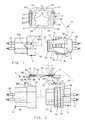
- Figure 1 is a top plan exploded view of anelectrical connector assembly comprising a pair ofelectrical connector bodies and a connector positionassurance member;
- Figure 2 is an exploded side elevationalview of the electrical connector assembly shown inFigure 1 and with the connector position assurancemember being shown in cross section;
- Figure 3 is a side elevational view of theelectrical connector assembly of the present inventionand showing the connector position assurance memberpartially connected to the mated connector bodies;
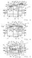
- Figure 4 is a view like that shown in Figure3, but showing the connector position assurance memberconnected to the mated connector bodies; and
- Figure 5 is a top plan view of theelectrical connector assembly shown in Figure 4, andwith portions thereof broken away and shown insection.
- Referring to the drawings, an
electricalconnector assembly 10 is shown therein. Theelectrical connector assembly 10 comprises a plugconnector body orplug connector 12, a female socketconnector orsocket connector 14 and a connectorposition assurance member 20. Theplug connector 12 could be of any suitable or conventional constructionand can be moulded from a suitable electricallyinsulating plastic material and have aforward plugportion 22. Theplug connector 12 has a plurality ofcavities (not shown) therethrough for housingelectrical terminals 24 which are suitably connectedto a cables or leads 26. The terminals 24 could be ofany suitable or conventional construction and would besuitably retained within the cavities in theplugconnector 12. - The
plug connector 12 also has acantileveredlock arm 30 extending both radiallyoutwardly therefrom and axially along theforward plugportion 22. Thelock arm 30 is bifurcated to define apair of spaced forwardly extendingsides 32 whichextend generally parallel to the longitudinal axis oftheplug connector 12 and which are joined at aforward bight 34. Thesides 32 are integrallyconnected to theplug connector 12 by radially oroutwardly extendinglegs 36. The spacedsides 32define aslot 35 therebetween. Thebight 34 isslanted upwardly or away from theforward plug portion 22 to define aramp surface 38, and for a reason to behereinafter more fully described. Thesides 32 of thelock arm 30 at their rearward ends define keeper tabsorprojections 40 which extend slightly rearwardly ofthelegs 36. Theplug connector 12 is also providedwith an annularelastomeric seal 42 which abuts anannular flange 43 at thelegs 36 of thelock arm 30. - The
socket connector 14 could be of anysuitable or conventional construction and can be madefrom a suitably electrically insulating plasticmaterial. Thesocket connector 14 has a centralopening (not shown) for receiving theforward plugportion 22 of theplug connector 12 and a plurality of cavities therethrough (not shown) forhousingterminals 50 matable with terminals 24 and connectedto cables or leads 52. Thesocket connector 14 at itsforward end portion 54 has a generallyplanar surface 56. Integral with theplanar surface 56 is aninclined ramp ortab 58 having an inclined rampsurface oredge 58a and an oppositely facing surfaceoredge 58b which extends perpendicular to thelongitudinal axis of thesocket connector 14. - The
plug connector 12 is connected to thesocket connector 14 by inserting the plug connectorinto the central opening (not shown) in thesocketconnector 14. As this occurs, theinclined surface 38of thebight 34 of thelock arm 30 will engage theinclined ramp surface 58a of theramp 58 to cause thelock arm 30 to be deflected radially outwardly of theplug connector 12. This occurs until theplugconnector 12 is fully mated or seated in thesocketconnector 14 and thebight 38 passes over theramp 58whereupon the self-biasing forces of thelock arm 30causes thebight portion 34 to snap behind thesurface 58b on theramp 58 and be locked there behind. Thisprovides the primary lock for connecting the twoconnectors matable terminals 50 and 24will be mated together and theseal 42 will engage aninner surface (not shown) in theforward end portion 54 defining the central opening in thesocketconnector 14 to provide a seal between theconnectors - In accordance with the provisions of thepresent invention, the connector
position assurancemember 20 is provided to insure that the plug andsocket connectors position assurance member 20 can be made from a suitable flexible, plasticmaterial, but is preferably made from nylon. Theconnectorposition assurance member 20 comprises a onepiece, thin or low profile member which is generallyof a rectangular frame shape withrounded corners 60.The connectorposition assurance member 20 has a largecentral through opening 62 and has a pair of spacedparallel sides orside portions 64 and a pair ofspaced parallel ends orend portions 66. Theconnectorposition assurance member 20 also hasopposed, parallel,planar sides endportions 66 at theirplanar sides linear ridges 69 extending transverselybetween theside portions 64 to aid in enabling anoperator to pick up and grip the connectorpositionassurance member 20. The connectorposition assurancemember 20 also includes a pair of bridges orbridgeportions 70. Eachbridge portion 70 at its ends isintegral with theside portions 64 and extendsparallel to, but spaced from, anadjacent end portion 66. The connectorposition assurance member 20includes transversely extendingelongated slots 74 toseparate thebridge portions 70 from theend portions 66. Thebridge portions 70 can be flexed toward andfrom theend portion 66 located adjacent thereto.Each of thebridge portions 70 includes, at itsmiddle, a notch or recess 76. Thebridge portions 70at their ends integral with theside portions 64 areof a lesser width so that thebridge portion 70 can bemore readily flexed toward and from theadjacent endportion 66. - It should be noted that the connector
position assurance member 20 has identicalplanarsides identical end portions 66 andbridge portions 70 so that it can be used in a completelyreversible fashion. - As best shown in Figures 3-5, the connector
position assurance member 20 is connected to theelectrical connector assembly 10 by placing oneendportion 66 thereof beneath thelock arm 30 adjacenttheramp 58 and thebridge portion 70 adjacent theother end portion 66 thereof on thelock arm 30adjacent thelegs 36. The connectorpositionassurance member 20 can then be moved in a directionto bring thesurface 58b of theramp 58 into theadjacently locatednotch 76 in thebridge portion 70and into engagement with thatbridge portion 70.Further movement of the connectorposition assurancemember 20 toward the right, will cause thebridgeportion 70 engaging theramp 58 to be deflectedtowards itsadjacent end portion 66 and will allow theother bridge portion 70 overlying thelock arm 30 toengage thekeeper projections 40 and then be deflectedtowards itsadjacent end portion 66 until it clearsthekeeper projections 40 and snaps thereunder, asshown in Figure 4. This snap over action will causean audible click to let the operator know that theconnection has been made. - It should be noted that once the
plugconnector 12 is connected to thesocket connector 14,the connectorposition assurance member 20 can beconnected thereto by the use of one hand. The audibleclick provides a positive indication to an operatorworking at a location difficult to reach and/or wherehe cannot see that theconnectors positionassurance device 20 is connected to theelectricalconnector assembly 10, thebridge portions 70 willbiasingly engage thesurface 58b of theramp 58 and thelegs 36 to biasingly hold the connectorpositionassurance member 20 in place without rattling. Itshould also be noted that the connectorpositionassurance member 20 also provides a secondary lock inthat it will prevent theconnectors - From the foregoing, it should be apparentthat a novel, one piece, low profile, completelyreversible connector position assurance member hasbeen provided which is of a simple and highlyeffective construction which can be applied fromeither end or either side, which can be attached withthe use of one hand and which provides a foolproofassurance that the connectors have been properlymated.
Claims (7)
- An electrical connector assembly (10)having a first connector (12) provided with anintegral deflectable cantilevered lock arm (30)extending axially along the first connector,said lock arm (30) comprises at least one keeper projection (40) extendingrearwardly from the rearward end of said lock arm (30); a secondconnector (14) matable with the first connector andhaving a transversely extending ramp (58), the lockarm engaging and being deflectable from a normal freestate position by the ramp when the first and secondconnectors are being mated until the lock arm clearsthe ramp whereupon self-biasing forces on the lock armreturn the lock arm towards the normal free stateposition to lock behind the ramp to lock the first andsecond connectors together; and a connector positionassurance means (20) for retaining the first andsecond connectors locked together; characterised inthat the connector position assurance means (20) isonly retainable on the first and second connectorswhen the first and second connectors are properlymated and comprises a substantially planar one-pieceflexible member having a central through opening (62),opposed end portions (66), and a transverse flexiblebridge portion (70) extending transverselyacross said opening adjacent and substantially parallel to one ofthe end portions and which can be flexed toward andaway from the one end portion, the connector positionassurance means (20) being connected to the first (12) andsecond (14) connectors when mated by positioning oneend portion under the lock arm (30) and sliding saidend portion towards the ramp (58), engaging the other endportion on the keeper projection (40) on the lockarm and then pushing the one end portion toward thefirst connector until the other end portion passes over the keeper projection (40) and snapsbeneath the keeper projection (40).
- An electrical connector assembly asclaimed in Claim 1, wherein the connector positionassurance means (20) includes a second flexible bridgeportion (70) extending transversely across said openingadjacent and substantially parallel to the other endportion (66) and which can be flexed toward and fromthe other end portion, the second bridge portionengaging the ramp (58) on connecting the connectorposition assurance means to the first and secondconnectors (12,14) such that the bridge portionsbiasingly engage the ramp and the lock arm.
- An electrical connector assembly asclaimed in Claim 2, wherein the end portions (66) andthe bridge portions (70) of the connector positionassurance means (20) are identical such that theconnector position assurance means is reversible.
- An electrical connector assembly asclaimed in Claim 3, wherein each bridge portion (70)has a notch (76) at its middle to receive the ramp(58).
- An electrical connector assembly asclaimed in any one of Claims 1 to 4, wherein each endportion (66) has linear ridges (69) to aid in grippingthe connector position assurance means (20).
- An electrical connector assembly asclaimed in any one of Claims 1 to 5, wherein the oreach bridge portion (70) has a reduced width at itsends.
- An electrical connector as claimed inany one of Claims 1 to 6, wherein the connectorposition assurance means (20) is made of plasticsmaterial and is substantially rectangular.
Applications Claiming Priority (2)
| Application Number | Priority Date | Filing Date | Title |
|---|---|---|---|
| US08/094,599US5308261A (en) | 1993-07-13 | 1993-07-13 | Low profile connector position assurance |
| US94599 | 1993-07-13 |
Publications (3)
| Publication Number | Publication Date |
|---|---|
| EP0665453A2 EP0665453A2 (en) | 1995-08-02 |
| EP0665453A3 EP0665453A3 (en) | 1995-08-23 |
| EP0665453B1true EP0665453B1 (en) | 1999-09-01 |
Family
ID=22246091
Family Applications (1)
| Application Number | Title | Priority Date | Filing Date |
|---|---|---|---|
| EP94201842AExpired - LifetimeEP0665453B1 (en) | 1993-07-13 | 1994-06-28 | Electrical connector assembly |
Country Status (5)
| Country | Link |
|---|---|
| US (1) | US5308261A (en) |
| EP (1) | EP0665453B1 (en) |
| JP (1) | JPH0778651A (en) |
| CA (1) | CA2122306C (en) |
| DE (1) | DE69420385T2 (en) |
Families Citing this family (16)
| Publication number | Priority date | Publication date | Assignee | Title |
|---|---|---|---|---|
| US5562475A (en)* | 1995-02-02 | 1996-10-08 | Aines Manufacturing Corp. | Modular telephone plug |
| DE29506134U1 (en)* | 1995-04-08 | 1996-08-01 | Robert Bosch Gmbh, 70469 Stuttgart | Electrical plug |
| DE19517221B4 (en)* | 1995-05-11 | 2004-12-02 | Hypertac Gmbh | Connector coupling for electrical line connectors |
| US5601446A (en)* | 1995-11-07 | 1997-02-11 | Osram Sylvania Inc. | Connector latch and assembly |
| US5775930A (en)* | 1996-12-13 | 1998-07-07 | General Motors Corporation | Electrical connector with locking connector position assurance member |
| US6116938A (en)* | 1997-08-28 | 2000-09-12 | The Whitaker Corporation | Low profile electrical connector |
| US5993237A (en)* | 1999-04-12 | 1999-11-30 | Aines Manufacturing Corp. | Modular telephone plug |
| JP2001057723A (en)* | 1999-08-10 | 2001-02-27 | Yazaki Corp | Electronic unit mounting structure to electrical junction box |
| US6672900B2 (en) | 2000-10-23 | 2004-01-06 | Robert Bosch Corporation | Universal aftermarket connector |
| US7267570B2 (en)* | 2005-07-22 | 2007-09-11 | Tyco Electronics Corporation | Double beam latch connector |
| US7413459B2 (en)* | 2006-09-08 | 2008-08-19 | Cyber Power System Inc. | Auxiliary device for a connector |
| CN103178401A (en)* | 2011-12-21 | 2013-06-26 | 鸿富锦精密工业(深圳)有限公司 | Connector plug |
| US8981961B2 (en)* | 2013-01-21 | 2015-03-17 | International Business Machines Corporation | Validation of mechanical connections |
| US9847009B2 (en) | 2015-09-26 | 2017-12-19 | Toyota Motor Engineering & Manufacturing North America, Inc. | Connection confirmation using acoustic data |
| JP7025373B2 (en)* | 2019-06-11 | 2022-02-24 | 矢崎総業株式会社 | housing |
| DE102019209235A1 (en)* | 2019-06-26 | 2020-12-31 | Robert Bosch Gmbh | Connectors |
Family Cites Families (4)
| Publication number | Priority date | Publication date | Assignee | Title |
|---|---|---|---|---|
| US4714433A (en)* | 1987-01-21 | 1987-12-22 | General Motors Corporation | Electrical connector with position assurance and double lock |
| US4801275A (en)* | 1987-11-30 | 1989-01-31 | Yazaki Corporation | Connector lock device |
| US4946395A (en)* | 1989-07-17 | 1990-08-07 | General Motors Corporation | Electrical connector with connector position assurance device |
| US5120240A (en)* | 1991-09-03 | 1992-06-09 | General Motors Corporation | Electrical connector with improved connector position assurance device |
- 1993
- 1993-07-13USUS08/094,599patent/US5308261A/ennot_activeExpired - Fee Related
- 1994
- 1994-04-27CACA002122306Apatent/CA2122306C/ennot_activeExpired - Fee Related
- 1994-06-28DEDE69420385Tpatent/DE69420385T2/ennot_activeExpired - Fee Related
- 1994-06-28EPEP94201842Apatent/EP0665453B1/ennot_activeExpired - Lifetime
- 1994-07-13JPJP6161330Apatent/JPH0778651A/ennot_activeWithdrawn
Also Published As
| Publication number | Publication date |
|---|---|
| EP0665453A2 (en) | 1995-08-02 |
| CA2122306A1 (en) | 1995-01-14 |
| JPH0778651A (en) | 1995-03-20 |
| EP0665453A3 (en) | 1995-08-23 |
| DE69420385T2 (en) | 1999-12-16 |
| CA2122306C (en) | 1997-10-14 |
| DE69420385D1 (en) | 1999-10-07 |
| US5308261A (en) | 1994-05-03 |
Similar Documents
| Publication | Publication Date | Title |
|---|---|---|
| EP0665453B1 (en) | Electrical connector assembly | |
| US5688142A (en) | Eletrical connector position assurance system | |
| KR100216002B1 (en) | Electrical connector with terminal position assurance device | |
| US5651689A (en) | Electrical connector assembly employing a connector position assurance device | |
| EP0241406B1 (en) | Sealed electrical connector assembly | |
| US4657331A (en) | Strain relief for electrical connector assemblies | |
| US4639061A (en) | Environmentally sealed connector | |
| US5643009A (en) | Electrical connector having a pivot lock | |
| EP0877390B1 (en) | Female electrical terminal | |
| JP2622935B2 (en) | Latch electrical connector | |
| EP0732775A2 (en) | Electrical connector position assurance system | |
| EP0510229B1 (en) | An electrical connector with positive latch | |
| EP0734101A2 (en) | Electrical connector position assurance system | |
| EP0241407B1 (en) | Electrical receptacle terminal | |
| JPH05275135A (en) | Female type electric terminal | |
| US4441776A (en) | Quick detachable coupling | |
| US5160279A (en) | Double lock connector | |
| EP0722205A2 (en) | Electrical connector assembly for interconnecting a flat cable to a circuit board | |
| KR100326219B1 (en) | Electrical connector with terminal position assurance device | |
| EP0902504B1 (en) | Front holder-incorporating connector | |
| EP1091452A1 (en) | Electrical connector with exposed molded latches | |
| US5651704A (en) | Electrical connector with terminal retainer | |
| US4717359A (en) | Arrangement for securing electrical terminal in terminal holder | |
| EP0975061B1 (en) | A watertight connector with inertial locking mechanism | |
| EP0926772A2 (en) | Electrical connector assembly with terminal position assurance device |
Legal Events
| Date | Code | Title | Description |
|---|---|---|---|
| PUAI | Public reference made under article 153(3) epc to a published international application that has entered the european phase | Free format text:ORIGINAL CODE: 0009012 | |
| PUAL | Search report despatched | Free format text:ORIGINAL CODE: 0009013 | |
| AK | Designated contracting states | Kind code of ref document:A2 Designated state(s):DE FR GB IT | |
| AK | Designated contracting states | Kind code of ref document:A3 Designated state(s):DE FR GB IT | |
| 17P | Request for examination filed | Effective date:19960223 | |
| GRAG | Despatch of communication of intention to grant | Free format text:ORIGINAL CODE: EPIDOS AGRA | |
| 17Q | First examination report despatched | Effective date:19980916 | |
| GRAG | Despatch of communication of intention to grant | Free format text:ORIGINAL CODE: EPIDOS AGRA | |
| GRAH | Despatch of communication of intention to grant a patent | Free format text:ORIGINAL CODE: EPIDOS IGRA | |
| GRAH | Despatch of communication of intention to grant a patent | Free format text:ORIGINAL CODE: EPIDOS IGRA | |
| GRAA | (expected) grant | Free format text:ORIGINAL CODE: 0009210 | |
| AK | Designated contracting states | Kind code of ref document:B1 Designated state(s):DE FR GB IT | |
| REF | Corresponds to: | Ref document number:69420385 Country of ref document:DE Date of ref document:19991007 | |
| ET | Fr: translation filed | ||
| PG25 | Lapsed in a contracting state [announced via postgrant information from national office to epo] | Ref country code:GB Free format text:LAPSE BECAUSE OF NON-PAYMENT OF DUE FEES Effective date:20000628 | |
| PLBE | No opposition filed within time limit | Free format text:ORIGINAL CODE: 0009261 | |
| STAA | Information on the status of an ep patent application or granted ep patent | Free format text:STATUS: NO OPPOSITION FILED WITHIN TIME LIMIT | |
| 26N | No opposition filed | ||
| GBPC | Gb: european patent ceased through non-payment of renewal fee | Effective date:20000628 | |
| PG25 | Lapsed in a contracting state [announced via postgrant information from national office to epo] | Ref country code:DE Free format text:LAPSE BECAUSE OF NON-PAYMENT OF DUE FEES Effective date:20010403 | |
| PG25 | Lapsed in a contracting state [announced via postgrant information from national office to epo] | Ref country code:FR Free format text:LAPSE BECAUSE OF NON-PAYMENT OF DUE FEES Effective date:20010831 | |
| REG | Reference to a national code | Ref country code:FR Ref legal event code:ST | |
| PG25 | Lapsed in a contracting state [announced via postgrant information from national office to epo] | Ref country code:IT Free format text:LAPSE BECAUSE OF NON-PAYMENT OF DUE FEES;WARNING: LAPSES OF ITALIAN PATENTS WITH EFFECTIVE DATE BEFORE 2007 MAY HAVE OCCURRED AT ANY TIME BEFORE 2007. THE CORRECT EFFECTIVE DATE MAY BE DIFFERENT FROM THE ONE RECORDED. Effective date:20050628 | |
| PG25 | Lapsed in a contracting state [announced via postgrant information from national office to epo] | Ref country code:FR Free format text:LAPSE BECAUSE OF NON-PAYMENT OF DUE FEES Effective date:20000630 |