EP0661008B1 - Surface fastener manufacturing method - Google Patents
Surface fastener manufacturing methodDownload PDFInfo
- Publication number
- EP0661008B1 EP0661008B1EP94119496AEP94119496AEP0661008B1EP 0661008 B1EP0661008 B1EP 0661008B1EP 94119496 AEP94119496 AEP 94119496AEP 94119496 AEP94119496 AEP 94119496AEP 0661008 B1EP0661008 B1EP 0661008B1
- Authority
- EP
- European Patent Office
- Prior art keywords
- substrate sheet
- molten resin
- die wheel
- filaments
- surface fastener
- Prior art date
- Legal status (The legal status is an assumption and is not a legal conclusion. Google has not performed a legal analysis and makes no representation as to the accuracy of the status listed.)
- Expired - Lifetime
Links
Images


Classifications
- B—PERFORMING OPERATIONS; TRANSPORTING
- B29—WORKING OF PLASTICS; WORKING OF SUBSTANCES IN A PLASTIC STATE IN GENERAL
- B29C—SHAPING OR JOINING OF PLASTICS; SHAPING OF MATERIAL IN A PLASTIC STATE, NOT OTHERWISE PROVIDED FOR; AFTER-TREATMENT OF THE SHAPED PRODUCTS, e.g. REPAIRING
- B29C43/00—Compression moulding, i.e. applying external pressure to flow the moulding material; Apparatus therefor
- B29C43/32—Component parts, details or accessories; Auxiliary operations
- B29C43/44—Compression means for making articles of indefinite length
- B29C43/46—Rollers
- A—HUMAN NECESSITIES
- A44—HABERDASHERY; JEWELLERY
- A44B—BUTTONS, PINS, BUCKLES, SLIDE FASTENERS, OR THE LIKE
- A44B18/00—Fasteners of the touch-and-close type; Making such fasteners
- A44B18/0046—Fasteners made integrally of plastics
- A44B18/0049—Fasteners made integrally of plastics obtained by moulding processes
- B—PERFORMING OPERATIONS; TRANSPORTING
- B29—WORKING OF PLASTICS; WORKING OF SUBSTANCES IN A PLASTIC STATE IN GENERAL
- B29C—SHAPING OR JOINING OF PLASTICS; SHAPING OF MATERIAL IN A PLASTIC STATE, NOT OTHERWISE PROVIDED FOR; AFTER-TREATMENT OF THE SHAPED PRODUCTS, e.g. REPAIRING
- B29C43/00—Compression moulding, i.e. applying external pressure to flow the moulding material; Apparatus therefor
- B29C43/22—Compression moulding, i.e. applying external pressure to flow the moulding material; Apparatus therefor of articles of indefinite length
- B29C43/222—Compression moulding, i.e. applying external pressure to flow the moulding material; Apparatus therefor of articles of indefinite length characterised by the shape of the surface
- B—PERFORMING OPERATIONS; TRANSPORTING
- B29—WORKING OF PLASTICS; WORKING OF SUBSTANCES IN A PLASTIC STATE IN GENERAL
- B29C—SHAPING OR JOINING OF PLASTICS; SHAPING OF MATERIAL IN A PLASTIC STATE, NOT OTHERWISE PROVIDED FOR; AFTER-TREATMENT OF THE SHAPED PRODUCTS, e.g. REPAIRING
- B29C43/00—Compression moulding, i.e. applying external pressure to flow the moulding material; Apparatus therefor
- B29C43/22—Compression moulding, i.e. applying external pressure to flow the moulding material; Apparatus therefor of articles of indefinite length
- B29C43/28—Compression moulding, i.e. applying external pressure to flow the moulding material; Apparatus therefor of articles of indefinite length incorporating preformed parts or layers, e.g. compression moulding around inserts or for coating articles
- B—PERFORMING OPERATIONS; TRANSPORTING
- B29—WORKING OF PLASTICS; WORKING OF SUBSTANCES IN A PLASTIC STATE IN GENERAL
- B29C—SHAPING OR JOINING OF PLASTICS; SHAPING OF MATERIAL IN A PLASTIC STATE, NOT OTHERWISE PROVIDED FOR; AFTER-TREATMENT OF THE SHAPED PRODUCTS, e.g. REPAIRING
- B29C48/00—Extrusion moulding, i.e. expressing the moulding material through a die or nozzle which imparts the desired form; Apparatus therefor
- B29C48/03—Extrusion moulding, i.e. expressing the moulding material through a die or nozzle which imparts the desired form; Apparatus therefor characterised by the shape of the extruded material at extrusion
- B29C48/07—Flat, e.g. panels
- B29C48/08—Flat, e.g. panels flexible, e.g. films
- B—PERFORMING OPERATIONS; TRANSPORTING
- B29—WORKING OF PLASTICS; WORKING OF SUBSTANCES IN A PLASTIC STATE IN GENERAL
- B29C—SHAPING OR JOINING OF PLASTICS; SHAPING OF MATERIAL IN A PLASTIC STATE, NOT OTHERWISE PROVIDED FOR; AFTER-TREATMENT OF THE SHAPED PRODUCTS, e.g. REPAIRING
- B29C48/00—Extrusion moulding, i.e. expressing the moulding material through a die or nozzle which imparts the desired form; Apparatus therefor
- B29C48/03—Extrusion moulding, i.e. expressing the moulding material through a die or nozzle which imparts the desired form; Apparatus therefor characterised by the shape of the extruded material at extrusion
- B29C48/12—Articles with an irregular circumference when viewed in cross-section, e.g. window profiles
- B—PERFORMING OPERATIONS; TRANSPORTING
- B29—WORKING OF PLASTICS; WORKING OF SUBSTANCES IN A PLASTIC STATE IN GENERAL
- B29C—SHAPING OR JOINING OF PLASTICS; SHAPING OF MATERIAL IN A PLASTIC STATE, NOT OTHERWISE PROVIDED FOR; AFTER-TREATMENT OF THE SHAPED PRODUCTS, e.g. REPAIRING
- B29C48/00—Extrusion moulding, i.e. expressing the moulding material through a die or nozzle which imparts the desired form; Apparatus therefor
- B29C48/03—Extrusion moulding, i.e. expressing the moulding material through a die or nozzle which imparts the desired form; Apparatus therefor characterised by the shape of the extruded material at extrusion
- B29C48/131—Curved articles
- B—PERFORMING OPERATIONS; TRANSPORTING
- B29—WORKING OF PLASTICS; WORKING OF SUBSTANCES IN A PLASTIC STATE IN GENERAL
- B29C—SHAPING OR JOINING OF PLASTICS; SHAPING OF MATERIAL IN A PLASTIC STATE, NOT OTHERWISE PROVIDED FOR; AFTER-TREATMENT OF THE SHAPED PRODUCTS, e.g. REPAIRING
- B29C48/00—Extrusion moulding, i.e. expressing the moulding material through a die or nozzle which imparts the desired form; Apparatus therefor
- B29C48/25—Component parts, details or accessories; Auxiliary operations
- B29C48/30—Extrusion nozzles or dies
- B29C48/35—Extrusion nozzles or dies with rollers
- B—PERFORMING OPERATIONS; TRANSPORTING
- B29—WORKING OF PLASTICS; WORKING OF SUBSTANCES IN A PLASTIC STATE IN GENERAL
- B29C—SHAPING OR JOINING OF PLASTICS; SHAPING OF MATERIAL IN A PLASTIC STATE, NOT OTHERWISE PROVIDED FOR; AFTER-TREATMENT OF THE SHAPED PRODUCTS, e.g. REPAIRING
- B29C43/00—Compression moulding, i.e. applying external pressure to flow the moulding material; Apparatus therefor
- B29C43/32—Component parts, details or accessories; Auxiliary operations
- B29C43/44—Compression means for making articles of indefinite length
- B29C43/46—Rollers
- B29C2043/461—Rollers the rollers having specific surface features
- B—PERFORMING OPERATIONS; TRANSPORTING
- B29—WORKING OF PLASTICS; WORKING OF SUBSTANCES IN A PLASTIC STATE IN GENERAL
- B29C—SHAPING OR JOINING OF PLASTICS; SHAPING OF MATERIAL IN A PLASTIC STATE, NOT OTHERWISE PROVIDED FOR; AFTER-TREATMENT OF THE SHAPED PRODUCTS, e.g. REPAIRING
- B29C48/00—Extrusion moulding, i.e. expressing the moulding material through a die or nozzle which imparts the desired form; Apparatus therefor
- B29C48/03—Extrusion moulding, i.e. expressing the moulding material through a die or nozzle which imparts the desired form; Apparatus therefor characterised by the shape of the extruded material at extrusion
- B29C48/13—Articles with a cross-section varying in the longitudinal direction, e.g. corrugated pipes
- B—PERFORMING OPERATIONS; TRANSPORTING
- B29—WORKING OF PLASTICS; WORKING OF SUBSTANCES IN A PLASTIC STATE IN GENERAL
- B29L—INDEXING SCHEME ASSOCIATED WITH SUBCLASS B29C, RELATING TO PARTICULAR ARTICLES
- B29L2031/00—Other particular articles
- B29L2031/727—Fastening elements
- B29L2031/729—Hook and loop-type fasteners
- Y—GENERAL TAGGING OF NEW TECHNOLOGICAL DEVELOPMENTS; GENERAL TAGGING OF CROSS-SECTIONAL TECHNOLOGIES SPANNING OVER SEVERAL SECTIONS OF THE IPC; TECHNICAL SUBJECTS COVERED BY FORMER USPC CROSS-REFERENCE ART COLLECTIONS [XRACs] AND DIGESTS
- Y10—TECHNICAL SUBJECTS COVERED BY FORMER USPC
- Y10T—TECHNICAL SUBJECTS COVERED BY FORMER US CLASSIFICATION
- Y10T24/00—Buckles, buttons, clasps, etc.
- Y10T24/27—Buckles, buttons, clasps, etc. including readily dissociable fastener having numerous, protruding, unitary filaments randomly interlocking with, and simultaneously moving towards, mating structure [e.g., hook-loop type fastener]
Definitions
- This inventionrelates to a method for continuously molding a surface fastener, which has a multiplicity of engaging members on a surface of a plate-like substrate sheet, by extruding thermoplastic resin.
- the technology of extruding a substrate sheet using thermoplastic resin and, at the same time, molding hooks on one surface of the substrate sheetis already known by, for example, International Patent Application No. WO 87/06522.
- the molding method disclosed in this publicationcomprises extruding molten thermoplastic resin onto a circumferential surface of a drum-shape die wheel, in which a multiplicity of mold discs and a multiplicity of spacer plates are laminated alternately, filling the hook-forming cavities of the mold discs with the resin while pressing the resin on the drum surface to form a substrate sheet, and pulling molded hooks out of the cavities along with the substrate sheet in timed relation to the rotation of the drum while the resin is cooled.
- the mold dischas in one side surface hook-shape cavities extending radially from the circumferential surface toward the center and spaced circumferentially at predetermined distances.
- the side surfaces of the spacer plateare flat. The reason why the spacer plate is needed is that the cavities of the whole shape of the hook cannot. be formed in a single mold.
- the surface fastener manufacturing method disclosed in the above-mentioned publicationsince the surface fastener is merely molded continuously of thermoplastic resin, it would be extended due to a tension exerted on the surface fastener when it is cut into pieces, thus causing dimensional errors in the products. Further, when the resulting surface fastener is attached to a garment by sewing, the surface fastener would have cracks due to the sewing needle so that it cannot be sewn to the garment.
- EP-A-0 580 073published after the priority date of the present invention and therefore only relevant to novelty discloses a method and an apparatus for manufacturing a material-backed engaging member for surface fastener.
- the backing materialcan be knitted or woven, can be a non-woven cloth or paper or can be a porous foam resin or a porous synthetic resin sheet.
- the present inventorshave considered to attach a cloth, which is woven of warp and weft yarns, to the back surface of the substrate sheet, or to embed the cloth in the substrate sheet, while the substrate sheet and hooks are molded integrally.
- a clothwhich is woven of warp and weft yarns
- the characteristic of the surface fastenermay be changed according to the yarn density
- it is sometimes required to prevent the surface fastener only from being extended or only from being crackedit is not always necessary to give to the surface fastener toughness in both warp and weft directions. Consequently it has turned out that using the cloth is disadvantageous from an economical view point and in that it might impair the characteristic of the surface fastener.
- the fiber filamentsare used, it is possible to realize the optimum filament density simply by adjusting the number of filaments to be supplied and the speed of traverse, and it is possible to arrange the filaments either longitudinally or transversely easily. Accordingly it has turned out that using the fiber filaments is most advantageous.
- the method for continuously manufacturing a surface fastenercomprises:
- the method for continuously manufacturing a surface fastenercomprises the steps of introducing the molten resin extruded from the extrusion nozzle and the filaments into a predetermined gap for molding a plate-like substrate sheet between the nozzle and the die wheel, which has a multiplicity of hook-forming cavities in its circumferential surface and is rotatable in one direction, and at the same time, filling the engaging-member-forming cavities with a part of the molten resin, embedding the filaments in the substrate sheet of the extruded molten resin as the die wheel is driven to rotate in the direction of extrusion of the molten resin, successively forming a plurality of hooks integrally on a surface of the substrate sheet, and positively taking up the substrate sheet with the hooks molded thereon, after cooling by a suitable cooling means.
- the method for continuously manufacturing a surface fastenercomprises the steps of, continuously introducing a plurality of parallel fiber filaments straightly onto a plate-like substrate sheet of the extruded molten resin, which sheet revolves along the rotation of the die wheel, and/or traversing one or more of the fiber filaments by a predetermined width, to thereby fixedly attaching the fiber filaments to a surface of the substrate sheet, and positively taking up the substrate sheet with the hooks molded thereon, after cooling by a suitable cooling means.
- molten resin extruded from the extrusion nozzleis forced into a gap between the extrusion nozzle and the die wheel, and the hook-forming cavities are progressively filled with a part of the molten resin to mold the hooks and to continuously mold a plate-like substrate sheet having a predetermined thickness and a predetermined width.
- the molten resin in contact with the die wheelis guided around part of the circumferential surface of the die wheel by the guide roller, during which the molten resin is cooled from the inside of the die wheel to gradually become hard.
- the individual hooksare removed smoothly from the cavity as it elastically deforms into a straight form. Immediately after that, the individual hook restores its original shape and the resulting hook is gradually cooled to become hard.
- Each of the filaments introduced to the vicinity to the outlet of the extrusion nozzleadvances along the circumferential surface of the die wheel in the direction of rotation of the die wheel along the rotation of the die wheel while they are embedded in the molten resin.
- the filamentsare embedded in and fused with the substrate sheet.
- the substrate sheet with the filaments and hooks integrally formed therewithare cooled into a half-hardened state from the inside of the die wheel and then are positively taken up.
- the surface fastenerwill be discharged as the surface of the substrate sheet is pressed by the guide roller.
- the surface fastenersince a plurality of parallel straight filaments arranged longitudinally of the substrate sheet cross in the substrate sheet one or more filaments meandering as traversed, the surface fastener will not be extended under tension during cutting and will not be cracked during sewing.
- FIG. 1is a fragmentary vertical cross-sectional view showing a surface fastener, in which fiber filaments are fixed to the back surface of a substrate sheet longitudinally and transversely and engaging members are molded on the front surface of the substrate sheet, as manufactured on an apparatus according to a first embodiment of this invention.
- the engaging membersare hooks.
- the shape of the engaging membersshould by no means be limited to hooks but they may have different shape such as anchor etc.
- reference numeral 1designates an extrusion nozzle; the upper half of an end surface of the nozzle 1 is an arcuate surface 1a having a curvature virtually equal to that of a die wheel 2 described below, while the lower half end surface is an arcuate surface 1b having a predetermined gap between the arcuate surface 1b and a curved surface of the die wheel 2 for molding a plate-like substrate sheet 4a.
- the extrusion nozzle 1is a T-type die, from an outlet 1d of which molten resin 4 is to be extruded in the form of a sheet. According to this embodiment, the extrusion nozzle 1 has a centrally extending passageway 1c.
- the die wheel 2is positioned in such a manner that part of its circumferential surface is close to the upper arcuate surface 1a and is spaced a predetermined gap from the lower arcuate surface 1b, and that its axis is parallel to the outlet 1d.
- the circumferential surface of the die wheel 2has a multiplicity of hook-forming cavities 5. Since the structure of the die wheel 2 is substantially identical with the structure disclosed in International Patent Application No. WO87/06522 , it is described here briefly.
- the die wheel 2is in the form of a hollow drum having in it a water cooling jacket 2a. Centrally in the hollow drum, a multiplicity of ring-shape plates are laminated along the axis of the hollow drum.
- Each of every other ring-shape plateshas in the front and back surfaces a multiplicity of hook-forming cavities 5 with the base of each hook opening to the circumferential surface of the drum. Both the front and back surfaces of each of non-illustrated ring-shape plates adjacent to the ring-shape plate having the hook-forming cavities 5 are flat.
- the die wheel 2is rotatable, in a direction indicated by an arrow, as driven by a non-illustrated known drive unit.
- a plurality of fiber filaments Fare introduced into the gap between the upper arcuate surface 1a and the circumferential surface of the die wheel 2 via a plurality of parallel filament guides 8 arranged transversely of the extrusion nozzle 1.
- a first filament guide 8a indicated by solid linesis fixed to, for example, a non-illustrated frame and guides the filaments F straightly so as to feed them in the direction of rotation of the die wheel 2.
- a second filament guide 8b indicated by phantom lines in FIG. 1is reciprocatingly moved by a predetermined width of traverse in a direction parallel to the axis of the die wheel 2 by a traverse device which is widely used in the field of textile machines.
- the filaments F guided by the second filament guide 8bwill be introduced into the gap between the upper arcuate surface 1a and the circumferential surface of the die wheel 2, meandering over a predetermined width of traverse.
- a plurality of second filament guides 8bare arranged parallel to one another and have each a desired width of traverse so that various composite meandering patterns can be obtained, by synchronous traverse, as shown in FIGS. 5 through 7. Further, by varying the traverse speed, it is possible to vary as desired the distance of the filaments arranged in the direction of rotation of the die wheel 2.
- a guide roller 9is situated, and in front of the guide roller 9, a set of upper and lower discharge rollers 6, 7 is situated.
- the resin material and the fiber filament material to he used in this inventionare exemplified by thermoplastic resin such as nylon, polyester and polypropylene.
- the resin material and the filament materialmay be identical with or different from each other.
- the molten resin temperature, extrusion pressure, die wheel temperature, speed of rotation of the die wheel, etc.should of course be controlled in accordance with the material used.
- molten resin extruded from the extrusion nozzle 1is forced into the gap between the extrusion nozzle 1 and the die wheel 2 in rotation, and a part of the extruded molten resin 4 is gradually charged in the hook-forming cavities 5 to mold hooks 4b and to continuously mold the plate-like substrate sheet 4a having a predetermined thickness and a predetermined width.
- the molded substrate sheet and hooks 4a, 4bare moved around substantially a half of the circumferential surface of the die wheel 2 as guided by the guide roller 9, during which they are cooled from the inside of the die wheel 2 to gradually become hard.
- the individual filament F introduced to the vicinity to the outlet 1b of the extrusion nozzle 1advancesalong the circumferential surface of the die wheel 2 in the direction of rotation of the die wheel 2 along the rotation of the die wheel 2 while it is embedded in the molten resin.
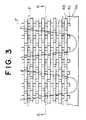
- the filaments Fare embedded in and fused with the substrate sheet 4a as shown in FIGS. 3 and 4.
- the substrate sheet 4a with the filaments F fused therewith and the hooks 4bare cooled into a half-hardened state from the inside of the die wheel 2 and then are positively taken up.
- the surface fasteneris discharged as the surface of the substrate sheet 4a is pressed by the guide roller 9.
- a set of upper and lower discharge rollers 6, 7 rotatable in. opposite directions in synchronism with each otheris used.
- the circumferential surfaces of the discharge rollers 6, 7may be smooth, it is preferable that they have grooves for receiving the rows of hooks 4b so that the hooks 4b are kept from being damaged.
- the rotating speed of the discharge rollers 6, 7is determined to be slightly larger than the rotating speed of the die wheel 2 so that the hooks 4b can be removed smoothly from the hook-forming cavities 5.
- the surface fastenersince a plurality of parallel straight filaments F arranged longitudinally of the substrate sheet 4a cross in the substrate sheet 4a one or more filaments F meandering as traversed, the surface fastener will not be extended under tension during cutting and will not be cracked during sewing.
- FIG. 2shows an apparatus for manufacturing a surface fastener with backing of filaments according to a second embodiment, in which the filament guide section of the first embodiment is modified.
- parts or elements substantially identical with those of the first embodimentare designated by like reference numerals.
- reference numeral 3designates a filament pressure roller situated under the extrusion nozzle 1 so as to simultaneously press the molten resin and filaments F against part of the circumferential surface of the die wheel 2.
- the first filament guide 8awhich guides the filaments F straightly in the direction of rotation of the die wheel 2, is situated under the filament pressure roller 3.
- the first filament guide 8aguides the filaments F in such a manner that the filament F goes around part of the circumferential surface of the filament pressure roller 3 and then supplies them to the gap between the pressure roller 3 and the die wheel 2.
- the second filament guide 8bis situated immediately upstream side of the resin pressing point between the die wheel 2 and the pressure roller 3, and likewise the first embodiment, supplies the filaments F while traversing by a predetermined width of traverse in the direction parallel to the axis of the die wheel 2.
- the upper arcuate surface 1a of the nozzle 1has a curvature virtually equal to that of the die wheel 2, while the lower arcuate surface 1b has a predetermined gap for molding the substrate sheet 4a between itself and the circumferential surface of the die wheel 2.
- the extrusion nozzle 1is the T-type die having the passageway 1c with the outlet 1d in the boundary of the upper and lower arcuate surfaces 1a, 1b, from which outlet 1d molten resin is to be extruded in the form of a sheet.
- the molten resin extruded from the extrusion nozzle 1is introduced into the gap defined between the extrusion nozzle 1 and the die wheel 2 and then fills the hook-forming cavities 5, which are provided in the circumferential surface of the die wheel 2, gradually along the rotation of the die wheel 2.
- the molten resin on the die wheel 2is moved around virtually a quarter of the circumferential surface of the die wheel 2 and then is removed from the die wheel 2, while being gradually cooled by a non-illustrated cooling device inside the die wheel 2.
- the filaments Fare guided simultaneously by the first and second filament guides 8a, 8b and are then fused integrally with the surface of the substrate sheet 4a, which are formed on the circumferential surface of the die wheel 2, as the filaments F are pressed against the surface of the substrate sheet 4a. At that time, if the filaments F are heated previously, there should be no difference in temperature between the filament F and the half-molten high-temperature substrate sheet 4a, thus causing reliable fusing.
- a multiplicity of hooks 4bare molded on the surface of the substrate sheet 4a, and the filaments F are arranged at desired distances longitudinally and transversely in the substrate sheet 4a as being fused with the substrate sheet 4a.
- this inventionshould by no means be limited to the foregoing embodiments, and it should not be necessary to arrange the filaments F in both the longitudinal and transverse directions, depending on the characteristic of the required surface fastener.
- a pair of traverse filaments Fmay be used as shown in FIG. 7, without arranging straight filaments F.
- only the straight filaments Fmay be arranged longitudinally of the substrate sheet 4a.
- a multiplicity of rows of hooks 4bare formed on the surface of the substrate sheet 4a and each of the hooks 4b has a pair of ribs 4c one on each of opposite side surfaces.
- the hooks 4bare directed in a common direction, and in the adjacent hook rows, they are directed in mutually opposite directions.
- the ribs 4care effective in preventing the hooks 4b from falling flat.
- the adjacent hooks 4bmay be directed in mutually opposite directions so that a surface fastener having no direction in coupling can be obtained.
- various kinds of molded surface fastenersin which filaments are arranged in the substrate sheet in various patterns can be continuously manufactured simply in a single process without requiring meticulous processes.
- the direction of engagement of the resulting surface fastenercan be selectively secured among only longitudinal, only transverse and both, depending on the arrangement of the filaments.
- This surface fasteneris excellent in dimensional precision as is free from being extended when it is cut into pieces in a subsequent step. Also in the sewing step, the surface fastener is free from any crack in the substrate sheet due to the sewing needle. Accordingly a durable and high-quality surface fastener can be obtained.
- the molten resinis extruded toward the die wheel in a direction right-angled to the peripheral surface of the die wheel.
- the molten resinmay be extruded between an upper die wheel and a lower press wheel both of which co-rotate in opposite directions.
Landscapes
- Engineering & Computer Science (AREA)
- Mechanical Engineering (AREA)
- Manufacturing & Machinery (AREA)
- Slide Fasteners, Snap Fasteners, And Hook Fasteners (AREA)
- Extrusion Moulding Of Plastics Or The Like (AREA)
- Injection Moulding Of Plastics Or The Like (AREA)
Description
- This invention relates to a method for continuouslymolding a surface fastener, which has a multiplicity ofengaging members on a surface of a plate-like substratesheet, by extruding thermoplastic resin.
- The technology of extruding a substrate sheet usingthermoplastic resin and, at the same time, molding hooks onone surface of the substrate sheet is already known by, forexample, International Patent ApplicationNo. WO 87/06522. The molding method disclosed in this publicationcomprises extruding molten thermoplastic resin ontoa circumferential surface of a drum-shape die wheel, in whicha multiplicity of mold discs and a multiplicity of spacerplates are laminated alternately, filling the hook-formingcavities of the mold discs with the resin while pressing theresin on the drum surface to form a substrate sheet, andpulling molded hooks out of the cavities along with the substratesheet in timed relation to the rotation of the drumwhile the resin is cooled. The mold disc has in one side surfacehook-shape cavities extending radially from the circumferentialsurface toward the center and spaced circumferentially at predetermined distances. The side surfaces of the spacerplate are flat. The reason why the spacer plate is needed isthat the cavities of the whole shape of the hook cannot. beformed in a single mold.
- According to the surface fastener manufacturing methoddisclosed in the above-mentioned publication, since the surfacefastener is merely molded continuously of thermoplastic resin,it would be extended due to a tension exerted on the surfacefastener when it is cut into pieces, thus causing dimensionalerrors in the products. Further, when the resulting surfacefastener is attached to a garment by sewing, the surfacefastener would have cracks due to the sewing needle so that itcannot be sewn to the garment.
- EP-A-0 580 073 published after the priority date of the present inventionand therefore only relevant to novelty discloses a method and an apparatusfor manufacturing a material-backed engaging member for surface fastener.The backing material can be knitted or woven, can be a non-woven cloth or paperor can be a porous foam resin or a porous synthetic resin sheet.
- It is an object ofthis invention to provide a molding method for manufacturinga surface fastener effectively and simply which is free ofextension though molded of thermoplastic resin by extrusion,is free from any crack during sewing and is stable in shape.
- As the result of various studies made in order toaccomplish the above object, the present inventors haveconsidered to attach a cloth, which is woven of warp and weftyarns, to the back surface of the substrate sheet, or toembed the cloth in the substrate sheet, while the substratesheet and hooks are molded integrally. In this case, however, assuming that the characteristic of the surface fastener maybe changed according to the yarn density, it would be necessaryto prepare various kinds of cloth having differenet densities.Additionally, since it is sometimes required to prevent thesurface fastener only from being extended or only from beingcracked, it is not always necessary to give to the surfacefastener toughness in both warp and weft directions. Consequentlyit has turned out that using the cloth is disadvantageousfrom an economical view point and in that it mightimpair the characteristic of the surface fastener.
- In other words, if the fiber filaments are used, it ispossible to realize the optimum filament density simply byadjusting the number of filaments to be supplied and the speedof traverse, and it is possible to arrange the filamentseither longitudinally or transversely easily. Accordinglyit has turned out that using the fiber filaments is mostadvantageous. In order to mold the substrate sheet and thehooks integrally and to fuse the filaments of fiber materialfirmly with the substrate sheet, it is preferable to heatthe filaments before joining to the substrate sheet. If thesubstrate sheet is adequately melted, it is not alwaysnecessary to preheat the filaments.
- As claimed, the method for continuously manufacturing a surfacefastener, comprises:
- (a) continuously extruding molten resin from anextrusion nozzle in a predetermined width toward a peripheralsurface of a die sheel having a plurality of engaging-member-formingcavities for molding a plate-like substratesheet of a predetermined width, while filling said cavitieswith a part of said molten resin;
- (b) continuously introducing a plurality of individual fiber filamentsstraightly and parallel and/or so as tomeander over a predetermined width of traverse;
- (c) integrating said individual fiber filaments with said plate-likesubstrate sheet as said die wheel is driven torotate in the direction of extrusion of said molten resinand successively forming a plurality of engaging membersintegrally on a surface of said substrate sheet; and
- (d) positively taking up said molded surface fastenerafter cooling by a suitable means.
- According to a second aspect of the invention, also claimed,the method for continuously manufacturing a surfacefastener, comprises the steps ofintroducing the molten resin extruded from theextrusion nozzle and the filaments into a predetermined gap for molding a plate-like substrate sheet between the nozzleand the die wheel, which has a multiplicity of hook-formingcavities in its circumferential surface and is rotatable inone direction, and at the same time, filling the engaging-member-formingcavities with a part of the molten resin,embedding the filaments in the substrate sheet of the extrudedmolten resin as the die wheel is driven to rotate in thedirection of extrusion of the molten resin, successivelyforming a plurality of hooks integrally on a surface of thesubstrate sheet, and positively taking up the substrate sheetwith the hooks molded thereon, after cooling by a suitablecooling means.
- According to a third aspect of the invention, also claimed,the method for continuously manufacturing a surfacefastener, comprises the steps of,continuously introducinga plurality of parallel fiber filaments straightly ontoa plate-like substrate sheet of the extruded molten resin,which sheet revolves along the rotation of the die wheel, and/or traversing one or more of the fiber filaments by apredetermined width, to thereby fixedly attaching the fiberfilaments to a surface of the substrate sheet, and positivelytaking up the substrate sheet with the hooks molded thereon,after cooling by a suitable cooling means.
- More specifically, in manufacturing the surface fasteneraccording to the claimed method, molten resin extruded fromthe extrusion nozzle is forced into a gap between the extrusionnozzle and the die wheel, and the hook-forming cavities areprogressively filled with a part of the molten resin to moldthe hooks and to continuously mold a plate-like substratesheet having a predetermined thickness and a predeterminedwidth. The molten resin in contact with the die wheel isguided around part of the circumferential surface of the diewheel by the guide roller, during which the molten resin iscooled from the inside of the die wheel to gradually becomehard. During this hardening, as the substrate sheet ispulled by a suitable force in the direction of extrusion, theindividual hooks are removed smoothly from the cavity as itelastically deforms into a straight form. Immediately afterthat, the individual hook restores its original shape and theresulting hook is gradually cooled to become hard.
- Each of the filaments introduced to the vicinity to theoutlet of the extrusion nozzle advances along the circumferentialsurface of the die wheel in the direction of rotation of the die wheel along the rotation of the die wheel whilethey are embedded in the molten resin. As a result, thefilaments are embedded in and fused with the substrate sheet.The substrate sheet with the filaments and hooks integrallyformed therewith are cooled into a half-hardened state fromthe inside of the die wheel and then are positively taken up.At a position immediately downstream of the die wheel, thesurface fastener will be discharged as the surface of thesubstrate sheet is pressed by the guide roller.
- In the resulting surface fastener, since a plurality ofparallel straight filaments arranged longitudinally of thesubstrate sheet cross in the substrate sheet one or morefilaments meandering as traversed, the surface fastener willnot be extended under tension during cutting and will not becracked during sewing.
- FIG. 1 is a fragmentary vertical cross-sectional viewshowing a molding apparatus for manufacturing a moldedsurface fastener, with backing of filaments, for carryingout a first embodiment of this invention;
- FIG. 2 is a fragmentary vertical cross-sectional viewshowing another molding apparatus for carrying out a secondembodiment of the invention;
- FIG. 3 is a fragmentary plan view showing an exampleof surface fastener manufactured according to the first embodiment;
- FIG. 4 is a cross-sectional view taken along line A-Aof FIG. 3;
- FIG. 5 is a plan view showing an example of arrangementof filaments according to this invention;
- FIG. 6 is a plan view showing another example ofarrangement of filaments; and
- FIG. 7 is a plan view showing still another exampleof arrangement of filaments.
- Embodiments of this invention will now be described indetail with reference to the accompanying drawings.
- FIG. 1 is a fragmentary vertical cross-sectional viewshowing a surface fastener, in which fiber filaments are fixedto the back surface of a substrate sheet longitudinally andtransversely and engaging members are molded on the front surfaceof the substrate sheet, as manufactured on an apparatusaccording to a first embodiment of this invention. In thefirst embodiment and a second embodiment described later,the engaging members are hooks. However, the shape of theengaging members should by no means be limited to hooks butthey may have different shape such as anchor etc.
- In FIG. 1, reference numeral 1 designates an extrusionnozzle; the upper half of an end surface of the nozzle 1is an arcuate surface 1a having a curvature virtually equal to that of a die wheel 2 described below, while the lower halfend surface is an arcuate surface 1b having a predeterminedgap between the arcuate surface 1b and a curved surface ofthe die wheel 2 for molding a plate-
like substrate sheet 4a.The extrusion nozzle 1 is a T-type die, from an outlet 1d ofwhichmolten resin 4 is to be extruded in the form of a sheet.According to this embodiment, the extrusion nozzle 1 has acentrally extending passageway 1c. - The die wheel 2 is positioned in such a manner thatpart of its circumferential surface is close to the upperarcuate surface 1a and is spaced a predetermined gap fromthe lower arcuate surface 1b, and that its axis is parallelto the outlet 1d. The circumferential surface of the diewheel 2 has a multiplicity of hook-forming cavities 5. Sincethe structure of the die wheel 2 is substantially identicalwith the structure disclosed in International Patent ApplicationNo. WO87/06522 , it is describedhere briefly. The die wheel 2 is in the form of a hollow drumhaving in it a water cooling jacket 2a. Centrally in thehollow drum, a multiplicity of ring-shape plates are laminatedalong the axis of the hollow drum. Each of every other ring-shapeplates has in the front and back surfaces a multiplicityof hook-forming cavities 5 with the base of each hook openingto the circumferential surface of the drum. Both the frontand back surfaces of each of non-illustrated ring-shape plates adjacent to the ring-shape plate having the hook-formingcavities 5 are flat. The die wheel 2 is rotatable, in adirection indicated by an arrow, as driven by a non-illustratedknown drive unit.
- A plurality of fiber filaments F are introduced into thegap between the upper arcuate surface 1a and the circumferentialsurface of the die wheel 2 via a plurality of
parallel filamentguides 8 arranged transversely of the extrusion nozzle 1.As shown in FIG. 1, afirst filament guide 8a indicated bysolid lines is fixed to, for example, a non-illustrated frameand guides the filaments F straightly so as to feed them inthe direction of rotation of the die wheel 2. Asecond filamentguide 8b indicated by phantom lines in FIG. 1 is reciprocatinglymoved by a predetermined width of traverse in adirection parallel to the axis of the die wheel 2 by a traversedevice which is widely used in the field of textile machines.Accordingly the filaments F guided by thesecond filament guide 8b will be introduced into the gap between the upper arcuatesurface 1a and the circumferential surface of the die wheel 2,meandering over a predetermined width of traverse. Likewisethe first filament guides 8a, a plurality of second filamentguides 8b are arranged parallel to one another and have eacha desired width of traverse so that various composite meanderingpatterns can be obtained, by synchronous traverse, as shownin FIGS. 5 through 7. Further, by varying the traverse speed, it is possible to vary as desired the distance of the filamentsarranged in the direction of rotation of the die wheel 2. - Further, in front (on the right side in FIG. 1) of thedie wheel 2, a guide roller 9 is situated, and in front of theguide roller 9, a set of upper and
lower discharge rollers 6,7 is situated. - The resin material and the fiber filament material tohe used in this invention are exemplified by thermoplasticresin such as nylon, polyester and polypropylene. The resinmaterial and the filament material may be identical with ordifferent from each other. During the molding, the moltenresin temperature, extrusion pressure, die wheel temperature,speed of rotation of the die wheel, etc. should of course becontrolled in accordance with the material used.
- According to the apparatus constructed as mentionedabove, molten resin extruded from the extrusion nozzle 1is forced into the gap between the extrusion nozzle 1 andthe die wheel 2 in rotation, and a part of the extruded
moltenresin 4 is gradually charged in the hook-forming cavities 5 tomold hooks 4b and to continuously mold the plate-like substratesheet 4a having a predetermined thickness and a predeterminedwidth. The molded substrate sheet and hooks 4a, 4b are movedaround substantially a half of the circumferential surface ofthe die wheel 2 as guided by the guide roller 9, during whichthey are cooled from the inside of the die wheel 2 to gradually become hard. During this hardening, when the moldedsubstratesheet 4a is pulled in the direction of extrusion by a suitableforce, theindividual hooks 4b is removed smoothly from thecavities 5 as they elastically deform into a straight form.Immediately after that, thehooks 4b restore their originalshape and hence are gradually cooled to become hard. - The individual filament F introduced to the vicinityto the outlet 1b of the extrusion nozzle 1 advancesalong thecircumferential surface of the die wheel 2 in the directionof rotation of the die wheel 2 along the rotation of the diewheel 2 while it is embedded in the molten resin. As aresult, the filaments F are embedded in and fused with the
substrate sheet 4a as shown in FIGS. 3 and 4. Thesubstratesheet 4a with the filaments F fused therewith and thehooks 4b are cooled into a half-hardened state from the inside ofthe die wheel 2 and then are positively taken up. At aposition immediately downstream of the die wheel 2, thesurface fastener is discharged as the surface of thesubstratesheet 4a is pressed by the guide roller 9. - In this embodiment, in order to remove the resin moldedproduct (surface fastener with backing of filaments) from thedie wheel 2, a set of upper and
lower discharge rollers 6, 7rotatable in. opposite directions in synchronism with eachother is used. Although the circumferential surfaces of thedischarge rollers 6, 7 may be smooth, it is preferable that they have grooves for receiving the rows ofhooks 4b so thatthehooks 4b are kept from being damaged. The rotating speedof thedischarge rollers 6, 7 is determined to be slightlylarger than the rotating speed of the die wheel 2 so thatthehooks 4b can be removed smoothly from the hook-formingcavities 5. - In the resulting surface fastener, since a plurality ofparallel straight filaments F arranged longitudinally of the
substrate sheet 4a cross in thesubstrate sheet 4a one or morefilaments F meandering as traversed, the surface fastener willnot be extended under tension during cutting and will not becracked during sewing. - FIG. 2 shows an apparatus for manufacturing a surfacefastener with backing of filaments according to a secondembodiment, in which the filament guide section of the firstembodiment is modified. In the second embodiment, parts orelements substantially identical with those of the firstembodiment are designated by like reference numerals.
- In FIG. 2, reference numeral 3 designates a filamentpressure roller situated under the extrusion nozzle 1 so asto simultaneously press the molten resin and filaments Fagainst part of the circumferential surface of the die wheel2. The
first filament guide 8a, which guides the filaments Fstraightly in the direction of rotation of the die wheel 2,is situated under the filament pressure roller 3. Thefirst filament guide 8a guides the filaments F in such a mannerthat the filament F goes around part of the circumferentialsurface of the filament pressure roller 3 and then suppliesthem to the gap between the pressure roller 3 and the diewheel 2. Thesecond filament guide 8b is situated immediatelyupstream side of the resin pressing point between the diewheel 2 and the pressure roller 3, and likewise the firstembodiment, supplies the filaments F while traversing by apredetermined width of traverse in the direction parallel tothe axis of the die wheel 2. - Therefore, in the second embodiment, the upper arcuatesurface 1a of the nozzle 1 has a curvature virtually equalto that of the die wheel 2, while the lower arcuate surface1b has a predetermined gap for molding the
substrate sheet 4abetween itself and the circumferential surface of the diewheel 2. The extrusion nozzle 1 is the T-type die having thepassageway 1c with the outlet 1d in the boundary of the upperand lower arcuate surfaces 1a, 1b, from which outlet 1d moltenresin is to be extruded in the form of a sheet. - According to the second embodiment, the molten resinextruded from the extrusion nozzle 1 is introduced into thegap defined between the extrusion nozzle 1 and the die wheel 2and then fills the hook-forming cavities 5, which are providedin the circumferential surface of the die wheel 2, graduallyalong the rotation of the die wheel 2. The molten resin on the die wheel 2 is moved around virtually a quarter of thecircumferential surface of the die wheel 2 and then is removedfrom the die wheel 2, while being gradually cooled by a non-illustratedcooling device inside the die wheel 2.
- During this molding, the filaments F are guided simultaneouslyby the first and second filament guides 8a, 8b andare then fused integrally with the surface of the
substratesheet 4a, which are formed on the circumferential surface ofthe die wheel 2, as the filaments F are pressed against thesurface of thesubstrate sheet 4a. At that time, if the filamentsF are heated previously, there should be no differencein temperature between the filament F and the half-moltenhigh-temperature substrate sheet 4a, thus causing reliablefusing. - As mentioned above, in the surface fastener manufacturedaccording to each of the foregoing embodiments, a multiplicityof
hooks 4b are molded on the surface of thesubstrate sheet 4a,and the filaments F are arranged at desired distances longitudinallyand transversely in thesubstrate sheet 4a as beingfused with thesubstrate sheet 4a. However, this inventionshould by no means be limited to the foregoing embodiments,and it should not be necessary to arrange the filaments F inboth the longitudinal and transverse directions, dependingon the characteristic of the required surface fastener. Apair of traverse filaments F may be used as shown in FIG. 7, without arranging straight filaments F. Alternatively, onlythe straight filaments F may be arranged longitudinally ofthesubstrate sheet 4a. - In the foregoing embodiments, as is apparent fromFIGS. 3 and 4, a multiplicity of rows of
hooks 4b are formedon the surface of thesubstrate sheet 4a and each of thehooks 4b has a pair ofribs 4c one on each of opposite side surfaces.In the same hook row, thehooks 4b are directed in a commondirection, and in the adjacent hook rows, they are directedin mutually opposite directions. Although they may be omitted,theribs 4c are effective in preventing thehooks 4b fromfalling flat. In this invention, in the same hook row, theadjacent hooks 4b may be directed in mutually opposite directionsso that a surface fastener having no direction incoupling can be obtained. Various modifications may besuggested within the scope and concept of this invention. - As is explained above in detail, according to themolding method of this invention, various kinds of moldedsurface fasteners, in which filaments are arranged in thesubstrate sheet in various patterns can be continuouslymanufactured simply in a single process without requiringmeticulous processes. The direction of engagement of theresulting surface fastener can be selectively secured amongonly longitudinal, only transverse and both, depending onthe arrangement of the filaments. This surface fastener is excellent in dimensional precision as is free from beingextended when it is cut into pieces in a subsequent step.Also in the sewing step, the surface fastener is free fromany crack in the substrate sheet due to the sewing needle.Accordingly a durable and high-quality surface fastener canbe obtained.
- In the above-described embodiments, the molten resinis extruded toward the die wheel in a direction right-angledto the peripheral surface of the die wheel. Alternatively,the molten resin may be extruded between an upper die wheeland a lower press wheel both of which co-rotate in oppositedirections.
Claims (5)
- A method for continuously manufacturing a surfacefastener, comprising:(a) continuously extruding molten resin (4) from anextrusion nozzle (1) in a predetermined width toward a peripheralsurface of a die wheel (2) having a plurality of engaging-member-formingcavities (5) for molding a plate-like substratesheet (4a) of a predetermined width, while filling said cavities(5) with a part of said molten resin (4);(b) continuously introducing a plurality of individual fiber filaments(F) straightly and parallel and/or so as tomeander over a predetermined width of traverse;(c) integrating said individual fiber filaments (F) with said plate-likesubstrate sheet (4a) as said die wheel (2) is driven torotate in the direction of extrusion of said molten resin (4),and successively forming a plurality of engaging members (4b)integrally on a surface of said substrate sheet (4a) ; and(d) positively taking up said molded surface fastenerafter cooling by a suitable means (2a).
- A method for continuously manufacturing a surfacefastener, according to claim 1 comprising the steps of:introducing said molten resin (4) extruded from saidextrusion nozzle (1) and said filaments (F) into a predeterminedgap for molding a plate-like substrate sheet (4a) between saidnozzle (1) and said die wheel (2), which has said multiplicity ofengaging-member-forming cavities (5) in its circumferentialsurface and is rotatable in one direction, and at the same time,filling said engaging-member-forming cavities (5) with a part ofsaid molten resin (4);embedding said filaments (F) in said plate-likesubstrate sheet (4a) of said extruded molten resin (4) as saiddie wheel (2) is driven to rotate in the direction of extrusionof said molten resin (4), and successively forming aplurality of engaging members (4b) integrally on a surface ofsaid substrate sheet (4a); andpositively taking up said substrate sheet (4a) withsaid engaging members (4b) molded thereon, after cooling by asuitable cooling means (2a).
- A method for continuously manufacturing a surfacefastener, according to claim 1 comprising the steps of:introducing said molten resin (4) into a predeterminedgap for molding a plate-like substrate sheet (4a) between saidnozzle (1) and a die wheel (2), which has said multiplicity ofengaging-member-forming cavities (5) in its circumferentialsurface and is rotatable in one direction, and at the same time,filling said engaging-member-forming cavities (5) with a part ofsaid molten resin (4);continuously introducing saidfiber filaments (F) onto said plate-like substratesheet (4a) of said extruded molten resin (4), which sheet (4a)revolves along the rotation of said die wheel (2),to thereby fixedly attaching said fiberfilaments (F) to a surface of said substrate'sheet (4a); andpositively taking up said substrate sheet (4a) withsaid engaging members (4b) molded thereon, after cooling bya suitable cooling means (2a).
- A method as defined in any preceding claim wherein saidfiber filaments are introduced straightly and parallel.
- A method as defined in any preceding claim wherein saidfiber filaments are introduced so as to meander over a predeterminedwidth of traverse.
Applications Claiming Priority (3)
| Application Number | Priority Date | Filing Date | Title |
|---|---|---|---|
| JP5337498AJP2731106B2 (en) | 1993-12-28 | 1993-12-28 | Manufacturing method of hook-and-loop fastener |
| JP337498/93 | 1993-12-28 | ||
| JP33749893 | 1993-12-28 |
Publications (3)
| Publication Number | Publication Date |
|---|---|
| EP0661008A2 EP0661008A2 (en) | 1995-07-05 |
| EP0661008A3 EP0661008A3 (en) | 1996-08-28 |
| EP0661008B1true EP0661008B1 (en) | 2002-07-17 |
Family
ID=18309222
Family Applications (1)
| Application Number | Title | Priority Date | Filing Date |
|---|---|---|---|
| EP94119496AExpired - LifetimeEP0661008B1 (en) | 1993-12-28 | 1994-12-09 | Surface fastener manufacturing method |
Country Status (8)
| Country | Link |
|---|---|
| US (1) | US6143222A (en) |
| EP (1) | EP0661008B1 (en) |
| JP (1) | JP2731106B2 (en) |
| CN (1) | CN1048937C (en) |
| BR (1) | BR9405469A (en) |
| DE (1) | DE69430984T2 (en) |
| ES (1) | ES2177562T3 (en) |
| TW (1) | TW272960B (en) |
Families Citing this family (21)
| Publication number | Priority date | Publication date | Assignee | Title |
|---|---|---|---|---|
| US5260015A (en) | 1991-08-16 | 1993-11-09 | Velcro Industries, B.V. | Method for making a laminated hook fastener |
| US5692271A (en)* | 1995-03-07 | 1997-12-02 | Velcro Industries B.V. | Enhanced flexibility fastener, method and apparatus for its making, and product incorporating it |
| US5620769A (en)* | 1995-05-02 | 1997-04-15 | Ykk Corporation | Molded surface fastener and method for manufacturing the same |
| JPH08322609A (en)* | 1995-06-02 | 1996-12-10 | Ykk Kk | Molded surface fastener and manufacturing method thereof |
| JPH09315A (en)* | 1995-06-20 | 1997-01-07 | Ykk Kk | Molded surface fastener and manufacturing method thereof |
| JPH10146206A (en)* | 1996-09-19 | 1998-06-02 | Ykk Corp | Integrated molded surface fastener member and method of manufacturing the same |
| US5981027A (en)* | 1996-11-26 | 1999-11-09 | Velcro Industries B.V. | Fastening member with loops and process and machine for producing it |
| JPH1146811A (en)* | 1997-08-05 | 1999-02-23 | Ykk Corp | Female engaging member for surface fastener and method of manufacturing the same |
| JPH11178853A (en) | 1997-12-24 | 1999-07-06 | Ykk Corp | Fasteners for disposable diapers, combinations of the fasteners and disposable diapers, and disposable diapers equipped with the fasteners |
| US20030070391A1 (en)* | 2000-04-26 | 2003-04-17 | Tachauer Ernesto S. | Fastening with wide fastening membrane |
| DE10039937A1 (en)* | 2000-08-16 | 2002-03-07 | Binder Gottlieb Gmbh & Co | Method of making an adhesive fastener part |
| US6484371B1 (en)* | 2001-02-27 | 2002-11-26 | 3M Innovative Properties Company | High strength, flexible, light weight hook and loop bundling straps |
| US6913810B2 (en) | 2002-01-15 | 2005-07-05 | Velcro Industries B.V. | Interface tape |
| US6692674B1 (en)* | 2002-11-27 | 2004-02-17 | Velcro Industries B.V. | Discrete fastener regions |
| EP1597055B1 (en)* | 2003-01-30 | 2010-08-18 | Tac-Fast Systems SA | Methods of manufacturing hook plates |
| US7373699B2 (en)* | 2003-10-15 | 2008-05-20 | Velcro Industries B.V. | Plastic sheet reinforcement |
| US7108814B2 (en)* | 2004-11-24 | 2006-09-19 | Velcro Industries B.V. | Molded touch fasteners and methods of manufacture |
| US7422783B2 (en)* | 2004-11-24 | 2008-09-09 | Velcro Industries B.V. | Submerged hooks |
| DE102008056052A1 (en)* | 2008-11-05 | 2009-09-17 | SaarGummi technologies S.à.r.l. | Continuous strand i.e. sealing strand, manufacturing method, involves continuously opening mold cavity at distance to casting position by guiding molding units away from each other to demold hard continuous strand in mold cavity |
| CN102940345B (en)* | 2012-11-28 | 2015-10-28 | 陈胜华 | The manufacture method of plastic hook fastener and equipment and plastic hook fastener |
| DE102015209394A1 (en)* | 2015-05-22 | 2016-11-24 | Leoni Kabel Holding Gmbh | Method and device for producing stranded and extruded material |
Family Cites Families (22)
| Publication number | Priority date | Publication date | Assignee | Title |
|---|---|---|---|---|
| US3168605A (en)* | 1963-10-03 | 1965-02-02 | Bayer Ag | Process for the production of webs of elastic synthetic resins |
| US3594865A (en)* | 1969-07-10 | 1971-07-27 | American Velcro Inc | Apparatus for molding plastic shapes in molding recesses formed in moving endless wire dies |
| US3608035A (en)* | 1969-08-01 | 1971-09-21 | Opti Holding Ag | Method of making slide fasteners |
| US3758657A (en)* | 1971-12-01 | 1973-09-11 | American Velcro Inc | Production of a continuous molded plastic strip |
| US4097634A (en)* | 1976-04-19 | 1978-06-27 | Minnesota Mining And Manufacturing Company | Thermoplastic resin molding of complex decorative relief |
| JPS54161439A (en)* | 1978-06-09 | 1979-12-21 | Yoshida Kogyo Kk | Method and device for making element train for slide fastener |
| JPS5656844A (en)* | 1979-10-17 | 1981-05-19 | Kasai Kogyo Co Ltd | Extrusion molding of plastic form |
| US4775310A (en)* | 1984-04-16 | 1988-10-04 | Velcro Industries B.V. | Apparatus for making a separable fastener |
| US4872243A (en)* | 1984-04-16 | 1989-10-10 | Velcro Industries B.V. | Multi-hook fastener member |
| US4769202A (en)* | 1985-11-29 | 1988-09-06 | The B. F. Goodrich Company | Process of making a conveyor belt |
| JPH01150528A (en)* | 1987-12-07 | 1989-06-13 | Kuraray Co Ltd | Thermoplastic resin sheet-like object excellent in antistatic property |
| US4999067A (en)* | 1989-02-13 | 1991-03-12 | Erblok Associates | Method for making a hermaphrodite hook and loop fasteners |
| WO1993000215A1 (en)* | 1991-06-21 | 1993-01-07 | The Procter & Gamble Company | Screen printing method for manufacturing a refastenable mechanical fastening system and fastening system produced therefrom |
| US5260015A (en)* | 1991-08-16 | 1993-11-09 | Velcro Industries, B.V. | Method for making a laminated hook fastener |
| JP2756211B2 (en)* | 1992-06-17 | 1998-05-25 | ワイケイケイ株式会社 | Method and apparatus for manufacturing integrally molded surface fastener having engagement pieces on both sides |
| JP2744384B2 (en)* | 1992-07-22 | 1998-04-28 | ワイケイケイ株式会社 | Method and apparatus for manufacturing engaging member having back member on back surface |
| US5550576A (en) | 1995-04-17 | 1996-08-27 | Starsight Telecast Incorporated | Method and apparatus for merging television program schedule information received from multiple television schedule information sources |
| US5620769A (en)* | 1995-05-02 | 1997-04-15 | Ykk Corporation | Molded surface fastener and method for manufacturing the same |
| JPH08299032A (en)* | 1995-05-09 | 1996-11-19 | Ykk Kk | Molded surface fastener |
| JPH08322609A (en)* | 1995-06-02 | 1996-12-10 | Ykk Kk | Molded surface fastener and manufacturing method thereof |
| JP3425501B2 (en)* | 1995-12-22 | 2003-07-14 | ワイケイケイ株式会社 | Hook-and-loop fastener |
| JPH1150528A (en)* | 1997-08-05 | 1999-02-23 | Okabe Co Ltd | Method for joining reinforced concrete column with beam |
- 1993
- 1993-12-28JPJP5337498Apatent/JP2731106B2/ennot_activeExpired - Lifetime
- 1994
- 1994-12-09EPEP94119496Apatent/EP0661008B1/ennot_activeExpired - Lifetime
- 1994-12-09ESES94119496Tpatent/ES2177562T3/ennot_activeExpired - Lifetime
- 1994-12-09DEDE69430984Tpatent/DE69430984T2/ennot_activeExpired - Fee Related
- 1994-12-09TWTW083111477Apatent/TW272960B/zhactive
- 1994-12-27CNCN94107614Apatent/CN1048937C/ennot_activeExpired - Fee Related
- 1994-12-28BRBR9405469Apatent/BR9405469A/ennot_activeIP Right Cessation
- 1996
- 1996-08-21USUS08/701,252patent/US6143222A/ennot_activeExpired - Fee Related
Also Published As
| Publication number | Publication date |
|---|---|
| US6143222A (en) | 2000-11-07 |
| BR9405469A (en) | 1995-09-19 |
| ES2177562T3 (en) | 2002-12-16 |
| DE69430984T2 (en) | 2003-02-20 |
| EP0661008A3 (en) | 1996-08-28 |
| EP0661008A2 (en) | 1995-07-05 |
| JPH07184707A (en) | 1995-07-25 |
| TW272960B (en) | 1996-03-21 |
| CN1108998A (en) | 1995-09-27 |
| DE69430984D1 (en) | 2002-08-22 |
| JP2731106B2 (en) | 1998-03-25 |
| CN1048937C (en) | 2000-02-02 |
Similar Documents
| Publication | Publication Date | Title |
|---|---|---|
| EP0661008B1 (en) | Surface fastener manufacturing method | |
| EP0830930B1 (en) | Molded surface fastener member and method of manufacturing the member | |
| EP0740910B1 (en) | Molded surface fastener and method for manufacturing the same | |
| EP0749707B1 (en) | Molded surface fastener and method for manufacturing the same | |
| CA2175176C (en) | Molded surface fastener | |
| EP0575828B1 (en) | Method and apparatus for continuously producing an integrally molded double-sided surface fastener | |
| US5537723A (en) | Molded surface fastener | |
| EP1078582B1 (en) | Female engaging member of surface fastener | |
| KR100288952B1 (en) | Female fastening member of the surface fastener and its manufacturing method | |
| EP0745337A1 (en) | Molded surface fastener and method for manufacturing the same | |
| HK1001488B (en) | Method and apparatus for continuously producing an integrally molded double-sided surface fastener | |
| HK1010645A (en) | Molded surface fastener and method for manufacturing the same | |
| HK1010657B (en) | Molded surface fastener and method for manufacturing the same | |
| HK1010658B (en) | Molded surface fastener | |
| HK1010641A (en) | Molded surface fastener and method for manufacturing the same | |
| HK1003373A (en) | Molded surface fastener with backing and method of manufacturing the same |
Legal Events
| Date | Code | Title | Description |
|---|---|---|---|
| PUAI | Public reference made under article 153(3) epc to a published international application that has entered the european phase | Free format text:ORIGINAL CODE: 0009012 | |
| AK | Designated contracting states | Kind code of ref document:A2 Designated state(s):BE DE ES FR GB IT | |
| PUAL | Search report despatched | Free format text:ORIGINAL CODE: 0009013 | |
| AK | Designated contracting states | Kind code of ref document:A3 Designated state(s):BE DE ES FR GB IT | |
| 17P | Request for examination filed | Effective date:19961128 | |
| 17Q | First examination report despatched | Effective date:19990210 | |
| GRAG | Despatch of communication of intention to grant | Free format text:ORIGINAL CODE: EPIDOS AGRA | |
| GRAG | Despatch of communication of intention to grant | Free format text:ORIGINAL CODE: EPIDOS AGRA | |
| GRAG | Despatch of communication of intention to grant | Free format text:ORIGINAL CODE: EPIDOS AGRA | |
| GRAH | Despatch of communication of intention to grant a patent | Free format text:ORIGINAL CODE: EPIDOS IGRA | |
| GRAH | Despatch of communication of intention to grant a patent | Free format text:ORIGINAL CODE: EPIDOS IGRA | |
| GRAA | (expected) grant | Free format text:ORIGINAL CODE: 0009210 | |
| AK | Designated contracting states | Kind code of ref document:B1 Designated state(s):BE DE ES FR GB IT | |
| REG | Reference to a national code | Ref country code:GB Ref legal event code:FG4D | |
| PGFP | Annual fee paid to national office [announced via postgrant information from national office to epo] | Ref country code:BE Payment date:20020718 Year of fee payment:9 | |
| REF | Corresponds to: | Ref document number:69430984 Country of ref document:DE Date of ref document:20020822 | |
| PGFP | Annual fee paid to national office [announced via postgrant information from national office to epo] | Ref country code:GB Payment date:20021204 Year of fee payment:9 | |
| PGFP | Annual fee paid to national office [announced via postgrant information from national office to epo] | Ref country code:FR Payment date:20021210 Year of fee payment:9 | |
| PGFP | Annual fee paid to national office [announced via postgrant information from national office to epo] | Ref country code:DE Payment date:20021212 Year of fee payment:9 | |
| REG | Reference to a national code | Ref country code:ES Ref legal event code:FG2A Ref document number:2177562 Country of ref document:ES Kind code of ref document:T3 | |
| ET | Fr: translation filed | ||
| PGFP | Annual fee paid to national office [announced via postgrant information from national office to epo] | Ref country code:ES Payment date:20030121 Year of fee payment:9 | |
| PLBE | No opposition filed within time limit | Free format text:ORIGINAL CODE: 0009261 | |
| STAA | Information on the status of an ep patent application or granted ep patent | Free format text:STATUS: NO OPPOSITION FILED WITHIN TIME LIMIT | |
| 26N | No opposition filed | Effective date:20030422 | |
| PG25 | Lapsed in a contracting state [announced via postgrant information from national office to epo] | Ref country code:GB Free format text:LAPSE BECAUSE OF NON-PAYMENT OF DUE FEES Effective date:20031209 | |
| PG25 | Lapsed in a contracting state [announced via postgrant information from national office to epo] | Ref country code:ES Free format text:LAPSE BECAUSE OF NON-PAYMENT OF DUE FEES Effective date:20031210 | |
| PG25 | Lapsed in a contracting state [announced via postgrant information from national office to epo] | Ref country code:BE Free format text:LAPSE BECAUSE OF NON-PAYMENT OF DUE FEES Effective date:20031231 | |
| BERE | Be: lapsed | Owner name:*YKK CORP. Effective date:20031231 | |
| PG25 | Lapsed in a contracting state [announced via postgrant information from national office to epo] | Ref country code:DE Free format text:LAPSE BECAUSE OF NON-PAYMENT OF DUE FEES Effective date:20040701 | |
| GBPC | Gb: european patent ceased through non-payment of renewal fee | Effective date:20031209 | |
| PG25 | Lapsed in a contracting state [announced via postgrant information from national office to epo] | Ref country code:FR Free format text:LAPSE BECAUSE OF NON-PAYMENT OF DUE FEES Effective date:20040831 | |
| REG | Reference to a national code | Ref country code:FR Ref legal event code:ST | |
| REG | Reference to a national code | Ref country code:ES Ref legal event code:FD2A Effective date:20031210 | |
| PG25 | Lapsed in a contracting state [announced via postgrant information from national office to epo] | Ref country code:IT Free format text:LAPSE BECAUSE OF NON-PAYMENT OF DUE FEES Effective date:20051209 |