EP0659060B1 - Clip for surgical use and clip applicator - Google Patents
Clip for surgical use and clip applicatorDownload PDFInfo
- Publication number
- EP0659060B1 EP0659060B1EP93915967AEP93915967AEP0659060B1EP 0659060 B1EP0659060 B1EP 0659060B1EP 93915967 AEP93915967 AEP 93915967AEP 93915967 AEP93915967 AEP 93915967AEP 0659060 B1EP0659060 B1EP 0659060B1
- Authority
- EP
- European Patent Office
- Prior art keywords
- clip
- clip portion
- pin
- bridge member
- flexible bridge
- Prior art date
- Legal status (The legal status is an assumption and is not a legal conclusion. Google has not performed a legal analysis and makes no representation as to the accuracy of the status listed.)
- Expired - Lifetime
Links
- 238000005452bendingMethods0.000claimsdescription4
- 230000001681protective effectEffects0.000claims2
- 230000000717retained effectEffects0.000claims1
- 230000001012protectorEffects0.000abstractdescription10
- 238000001356surgical procedureMethods0.000abstractdescription3
- 210000003811fingerAnatomy0.000description11
- 238000000034methodMethods0.000description9
- 230000008569processEffects0.000description9
- 238000007493shaping processMethods0.000description8
- 210000004204blood vesselAnatomy0.000description4
- 238000010276constructionMethods0.000description4
- 239000000463materialSubstances0.000description4
- 229910001220stainless steelInorganic materials0.000description3
- 210000003813thumbAnatomy0.000description3
- 206010002329AneurysmDiseases0.000description2
- 208000027418Wounds and injuryDiseases0.000description2
- 230000009471actionEffects0.000description2
- 230000000903blocking effectEffects0.000description2
- 230000006378damageEffects0.000description2
- 239000004744fabricSubstances0.000description2
- 208000014674injuryDiseases0.000description2
- 239000002184metalSubstances0.000description2
- 238000002324minimally invasive surgeryMethods0.000description2
- 239000010935stainless steelSubstances0.000description2
- 230000007704transitionEffects0.000description2
- 241001295925GegenesSpecies0.000description1
- 230000008859changeEffects0.000description1
- 210000000078clawAnatomy0.000description1
- 230000001419dependent effectEffects0.000description1
- 238000006073displacement reactionMethods0.000description1
- 239000003814drugSubstances0.000description1
- 238000002474experimental methodMethods0.000description1
- 238000007667floatingMethods0.000description1
- 230000004886head movementEffects0.000description1
- 230000002439hemostatic effectEffects0.000description1
- 230000003902lesionEffects0.000description1
- 238000002407reformingMethods0.000description1
Images


Classifications
- A—HUMAN NECESSITIES
- A61—MEDICAL OR VETERINARY SCIENCE; HYGIENE
- A61B—DIAGNOSIS; SURGERY; IDENTIFICATION
- A61B17/00—Surgical instruments, devices or methods
- A61B17/064—Surgical staples, i.e. penetrating the tissue
- A61B17/0644—Surgical staples, i.e. penetrating the tissue penetrating the tissue, deformable to closed position
- A—HUMAN NECESSITIES
- A61—MEDICAL OR VETERINARY SCIENCE; HYGIENE
- A61B—DIAGNOSIS; SURGERY; IDENTIFICATION
- A61B17/00—Surgical instruments, devices or methods
- A61B17/12—Surgical instruments, devices or methods for ligaturing or otherwise compressing tubular parts of the body, e.g. blood vessels or umbilical cord
- A61B17/122—Clamps or clips, e.g. for the umbilical cord
- A—HUMAN NECESSITIES
- A61—MEDICAL OR VETERINARY SCIENCE; HYGIENE
- A61B—DIAGNOSIS; SURGERY; IDENTIFICATION
- A61B17/00—Surgical instruments, devices or methods
- A61B17/12—Surgical instruments, devices or methods for ligaturing or otherwise compressing tubular parts of the body, e.g. blood vessels or umbilical cord
- A61B17/128—Surgical instruments, devices or methods for ligaturing or otherwise compressing tubular parts of the body, e.g. blood vessels or umbilical cord for applying or removing clamps or clips
- A61B17/1285—Surgical instruments, devices or methods for ligaturing or otherwise compressing tubular parts of the body, e.g. blood vessels or umbilical cord for applying or removing clamps or clips for minimally invasive surgery
Definitions
- the inventionrelates to a clip for use in surgery according to the preamble of the first claim and a clip applicator for setting the clip.
- a clip of the type mentionedis known from US 4,498,476.
- This clipwhich is used to clamp blood vessels, consists of an upper clip part and a lower clip part, which are connected to each other symmetrically by a flexible bridge part.
- the upper clip partcontains an opening into which a pin attached to the lower clip part engages.
- the pincarries a roof-like projecting or arrow-shaped tip. The pin and possibly the tip, together with the opening, act as locking elements for closing the clip. When closed, the upper part of the clip and the lower part of the clip touch. With this clip, tissue edges cannot be approximated and fixed.
- a surgical clampin particular a blood vessel clamp, which likewise consists of an upper part and a lower part, the upper and lower part being connected symmetrically to one another by a flexible bridge part.
- the upper partcontains an opening into which a ratchet can engage.
- the ratchethas teeth on one side, with the help of which the clamp can be closed and locked. Even with this clamp, tissue edges cannot be approximated and fixed.
- German utility model G 83 29 725describes a microclip for medical purposes made of elastically deformable material, which is made of a U-shaped part and attached to the free one Legs of the U attached and approximately parallel to the legs of the U, essentially straight sections, and is characterized in that the straight sections run at a short distance from the legs of the U and these only in the vicinity of the connection with the free legs of the Touch U
- the microclipis preferably made of soft-elastic stainless steel.
- the free ends of the Ucan contain openings at which a clip applicator can be attached.
- the known microclipis also mainly intended for the clamping of blood vessels; it seems less suitable for fixing tissue edges after incisions.
- microclipAnother surgical microclip is described in EP 0 432 743 A1.
- This microcliphas two flanges made of sheet metal lying opposite one another. On the flanges there are points directed towards one another at one end and grip areas which can be compressed against spring force at the other end.
- the microclipis formed in one piece and has a connecting flange which extends between the grip areas and is designed to be resiliently elastic.
- microclipsince it is obviously set by hand, must be relatively large and is therefore not suitable for internal surgery and in particular not for minimally invasive surgery (MIC).
- an aneurysm clipwhich has two pivotally connected, crossing legs, with the aid of which tissue can be fixed.
- the legsare pressed together with the help of a double turn of a spring wire, which is connected to the two legs.
- the last two clips describedare particularly suitable for the temporary clamping of blood vessels; they are not suitable for permanent fixation of tissue edges after incisions.
- a tube ligation pistolis known with which clips can be placed to interrupt vessels.
- the deviceis suitable for clips whose upper and lower parts can be folded against each other via an axis and which can be fixed by a spring.
- a clip application pliersis known from DE 40 24 636 A1. These clip-on pliers have a tube that can be moved in the axial direction with the aid of two handle halves. At the distal end of the tube two claws protrude, which can be opened and closed via a rope that is guided in the tube.
- the tubeconsists of a tubular elastic sheathing that remains stable when the rope is moved.
- the clip application forcepsare obviously used to apply aneurysm clips.
- the inventionhas for its object to provide a clip of the type mentioned and a clip applicator suitable for setting this clip, with the help of which in minimally invasive surgery (MIC) through a trocar sleeve tissue edges can be approximated and fixed after lesions or incisions.
- MICminimally invasive surgery
- the clip according to the inventionis shown in its final form set in the tissue in FIG. 1. It consists of a lower clip part 1 and an upper clip part 2, which are connected to one another by a flexible bridge part 8.
- the clipcan consist of a bendable material, such as a suitable stainless steel wire with a uniform diameter.
- a bendable materialsuch as a suitable stainless steel wire with a uniform diameter.
- the cross section of the bridge part 8is preferably reduced compared to the cross sections of the other parts of the clip. This ensures that the pin 9 can exert a high force on the tissue when the clip is set without bending, while the effort for bending the bridge part remains limited.
- the clip according to the inventionhas a plane of symmetry.
- the lower part of the clip 1carries at its free end an angled pin 9 in the plane of symmetry, which ends in a tip 10.
- the upper part of the clip 2has a rounded protector nose 12 at its free end. In the vicinity of the protector nose 12, the upper clip part 2 is provided with an opening 11 which is arranged in the plane of symmetry.
- the lengths of the lower clip part 1 with the pin 9, the flexible bridge part 8 and the upper clip part 2 up to the opening 11are dimensioned such that the pin 9 engages with its tip 10 in the opening 11 when the upper clip part 2 deforms the bridge part 8 against the clip base 1 is pressed.
- the tissue to be approximated and fixedis pierced and charged. Then the upper clip part 2 is pressed by bending the bridge part 8 so far against the pin 9 of the lower clip part 1 until the tip 10 engages through the opening 11.
- the cross section of the pen tip 10 and the cross section of the openingare chosen accordingly.
- the simplest solutionis one circular opening 11 and a conical or pyramidal tip 10.
- the protector nose 12is preferably bent in the same direction as the pin 9. This makes it possible to secure the clip against unintentional opening and at the same time to keep the pin tip 10 in such a way that further injuries to the fixed tissue are excluded.
- the pin tip 10 protruding from the opening 11is bent over in the direction of the protector nose 12, so that it is protected by the bent protector nose 12.
- bridge part 8 of the cliphas a smaller cross section and offset surfaces 6, 7 in the clip upper part 2 and clip lower part 1 are provided at the interface between these clip parts and your bridge part 8. It is also advantageous if a pin 3 is formed on both sides in the region of the clip upper part 2 adjacent to the bridge part 8, perpendicular to the plane of symmetry. Pins with a bevel 4 on the side facing away from the bridge part 8 are particularly preferred.
- the clip according to the inventioncan be punched out of sheet metal and then bent into the initial shape shown in FIG. 3. It consists of a single part, so that it is not necessary to assemble small individual parts. With appropriate choice of materials, e.g. B. a flexible stainless steel, the bridge part can be deformed several times without breaking.
- the clipcan be made so small that it can be placed with one of the common 5, 7 or 10 mm trocar sleeves.
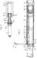
- FIGS. 2 to 8The embodiment of the clip applicator shown in FIGS. 2 to 8 is designed for one-hand operation. It allows the clip to be introduced in the form shown in FIG. 4 by means of a trocar sleeve of 5, 7 or 10 mm which is adapted to the applicator head 38 and the applicator shaft 21.
- the clipBy simply translating the shaft outer part consisting of the parts 22, 38 and 39 relative to the shaft inner part 23 and to the gripper 27, the clip is held in the form shown in FIG. 4 and inserted through the trocar sleeve, opened into the form shown in FIG. 5 , after loading and approximation of the tissue on the pin 9, as shown in FIG. 7, closed, locked as shown in FIG. 8 and then released.
- the closing and opening of the cliptakes place with deformation of the hinge bow 48 (FIG.
- the clip applicator and clipare matched to one another such that, according to FIG. 3, the pin back 5 on the pin 3 of the clip upper part 2 can be moved with sufficient play over the cover surfaces 45 of the opener pin 47 in the applicator head 38 as far as the stop and shaping rib 44 during the loading process.
- the clipWhen opening and closing, the clip translates approximately between the position shown in FIG. 5 and the beginning of the post-forming ribs 40 and 41 in the applicator head 38 (see FIG. 3).
- the construction of the applicator head 38 and the gripper 27 shownmeans that the radius of the hinge bow 48 remains relatively large in this working area and its plastic deformations lead to material failure only after an unrealistically large number of working cycles.
- the clip gripper 27 and thus also the gripped clipare ergonomically inexpensive and safely directable via the inner shaft part 23 and the palm grip part 14 by the hand of the surgeon. Closing and opening the clip in the operating position by moving the applicator head 38 and the shaft tube 39 when the finger grip part 13 is actuated does not lead to a dislocation of the clip, which would always have to be compensated for by a corrective hand movement by the operator.
- the applicator head 38is moved relative to the gripper 27 by actuating the finger grip part 13 from the position shown in FIG. 6 to the position shown in FIG.
- the finger grip part 13is then blocked against distal resetting into the starting position by the flat springs 52.
- the applicator head 38can be moved back and forth relative to the gripper 27 between two attachment points defined by the slide track.
- the clip for loading tissue edgesis opened (Fig. 5) and closed (Fig. 4). Unintentional release or locking of the clip is not possible.
- the spring lever 20is actuated with the thumb as described above.
- the tongue on the spring lever 20jumps into the lower-lying second part of the slide track 17.
- the hinge arch 48is reshaped under the reforming ribs 40 and 41, the upper clip part 2 is lowered (FIGS. 7 and 8), the pen tip 10 is bent onto the protector nose 12 and the clip is thereby locked (FIG. 8).
- the handle part 13is relieved, the action of the flat springs 52 pulls the applicator head 38 back proximally and releases the clip with the fixed tissue edges.
- the applicator shaft 21 including the applicator head 38, clip gripper 27 and drive head 16can be exchanged with the link tracks 17. It is advantageous from the design point of view that the applicator and drive heads are changed at the same time, so that the slide tracks 17 are always optimally adapted to the respective clip dimensions.
- the system proposed herealso consists of the clip and the associated applicator.
- the operating handle selected hereallows applicators with 5 mm, 7 mm and 10 mm shaft outer diameter to be driven in suitable trocar sleeves.
- the instrument shafts 21are changed by operating the two knurled screws 18 and 24 in the drive head 16 or handle head 15.
- the open clip as drawn in FIG. 3is taken over directly from a suitably shaped magazine or from tweezers by the clip gripper 27.
- the clip gripper 27is fully open, as shown in FIG.
- the clear distance between the gripper jaws 32 and the gripper heads 29is maximum in this position and is predetermined by the flat springs 31 bent outwards in this relaxed state.
- the applicator head 38When the bridge part 8 abuts the distal end of the stop rod 28, the applicator head 38 can be moved distally.
- the clip gripper 27is closed in accordance with the distance traveled by the applicator head 38 relative to the gripper heads 29.
- the clipWhen loading the gripper from an adapted magazine, it is ensured that during this process the clip is positioned exactly relative to the gripper heads 29 such that the bridge part 8 lies exactly between the proximal surfaces of the gripper jaws 32 and the distal end of the stop rod 28. Furthermore, it is then ensured that the position of the clip in the gripper heads 29 is fixed both by guiding the offset surfaces 7 of the lower clip part 1 on the index surfaces 34 of the gripper heads 29 and by guiding the offset surfaces 6 of the upper clip part 2 on the index surfaces 33.
- the gripper jaws 32can be closed, as described, by advancing the applicator head 38 in a distal direction.
- the guide ribs 30 on the gripper heads 29also track into the guide groove 51 and now secure the gripper 27 against gaping under load by supporting the gripper heads 29 on the walls of the groove 51.
- the guide ribs 30slide past the opener pin 47 in the applicator head.
- the gripper heads 29 with the lower clip part 1are drawn into the lower guide groove 42 of the applicator head 38.
- the clip shapeas shown in FIG. 3, remains unchanged until the clip upper part 2 touches the stop and shaping rib 44 in the applicator head 38.
- the flexible bridge 8is deformed in the area of the hinge bow 48 between the stop and shaping rib 44 and the gripper jaws 32 so that the clip upper part 2 begins a closing movement in the direction of the clip lower part 1.
- the clipthen has approximately the shape shown in Fig. 5.
- the upper clip part 2is still on the stop and forming rib 44th
- the tongue on the spring lever 20was first raised on an increasing surface of the first link path 17a against the spring force of its own shaft from the starting plane A by 2 s to the level B.
- Fig. 3shows the corresponding clip position in the applicator head.
- the finger grip part 13is secured against blocking in the starting position by blocking the drive head 16. Unintentional release of the clip is excluded.
- the closing movement of the clip initiated towards the end of the loading processis continued.
- the clipslides further into the guide grooves 42 and 51 a.
- the bridge 8 on the upper clip part 2is formed by the pair of forces between the gripper jaws 32 and the stop and shaping rib 44 to form the hinge arch 48.
- the pins 3 projecting laterally from the clip upper part 2pass through the gap between the opening pins 47 and the stop and deformation rib 44 into the guide groove 51, on the side surfaces of which they slide and thereby support the clip upper part 2 laterally.
- An additional side guide of the clip upper part 2is given in the course of the closing process by being immersed between the opening pins 47 in the applicator head 38 (FIG. 4).
- the distal feed path of the applicator head 38 relative to the clip gripper 27is limited by the stop of the spring lever tongue at the proximal end of the first link path 17 on the plane C in the drive head 16. An unintentional locking of the clip when driving under the post-forming ribs 40 and 41 is therefore excluded. As long as the applicator head 38 is moved relative to the clip gripper 27 in an area which is delimited by the distal and proximal stop on the plane C of the first link path 17, the clip remains secured against unintentional release and locking.
- the clipmust be opened in the surgical field to grip and load the first tissue edge.
- the finger grip part 13is relieved and moved back between the grip parts by the appropriately dimensioned flat springs 52.
- the applicator head 38is thereby displaced proximally.
- the tip 10 of the pin 9 on the lower clip part 1is placed near the edge of the incision on the outer surface (the surface that would point to the applicator without an incision) of the tissue and an axial movement of the pin attempts to pierce the tissue.
- This experimentis supported by careful longitudinal movement of the applicator proximally. This creates an additional force component in the direction of the pin axis on the pin tip 10 inclined towards the clip bridge.
- the applicator head 38is moved distally relative to the clip gripper 27 by tightening the finger grip part 13, and the clip is closed as described above.
- the tissue cross section lying between the pen tip 10 and the opening 11 in the clip upper part 2is more easily pierced because of the minimized elastic deflection and because of the counterforce of the upper part, and the tissue edge is charged onto the tip.
- the fabric edge lying in the clear cross section of the clipmigrates into the mouth 26 of the applicator head 38 when the clip is closed.
- the spring lever 20is pressed against the resistance of the flat spring 50 towards the grip head 15 with the clip of FIG.
- the tongue of the spring lever 20falls back to level A in the second slide track 17 by s. After this brief one-time pressure on the spring lever 20, the tongue is caught in the slide track 17. It slides along the step between the grooves 17 and thereby prevents the spring lever 20 from being reset before the clip is released.
- the hinge arch 48 of the clipfirst touches the oblique contact surfaces 49 of the post-forming ribs 40 and 41.
- the distal end of the clip upper part 2moves further towards the lower clip part 1, deforming the hinge bow 48, until the lower one Edge of the opening 11 is placed on the oblique edges of the pen tip 10.
- the hinge arch 48is pressed under the post-forming ribs 40 and 41, thereby bringing the clip upper part 2 into the shape shown in FIG.
- the pin tip 10 on the stop and shaping rib 44is also bent and slides into the guide groove 51.
- the protector nose 12 on the clip upper part 2is bent more or less straight depending on the thickness and elastic counterforce of the tissue in the clip.
- the restoring forces of the protector nose 12 after the deformationensure, by supporting the edge of the hole in the clip upper part 2 on the edges of the pen tip 10, that the tip rests on the protector nose and thus the bearing tissue of the clip against injury.
- the upper part of the clip 2has been moved further to the axis of the applicator mouth 26 by the reshaping and closing process from the bottom of the guide groove 51, in which the opening and closing of the clip has been realized by translational sliding (FIG. 8).
- the pins 3 on the upper clip part 2are now, as shown in FIG. 8, in a plane below the opening pins 47. If the applicator head 38 is withdrawn proximally, the pins 3 slide on the upper clip part 2 under the opening pins 47.
- the flat springs 31open the gripper heads 29 comprising the clipping bridge 8, and the gripper jaws 32 release the clip shaped in accordance with FIG. 1 with the enclosed tissue edges.
- the tongue of the spring hoist 20jumps back on level A from the second slide track 17 into the first slide track 17 due to the pressure of the flat fields 50.
- the spring lever 20is thus again in the starting position.
- the applicatorcan be removed with the above gripper 27 through the trocar sleeve from the surgical site and immediately loaded with the next clip.
Landscapes
- Health & Medical Sciences (AREA)
- Surgery (AREA)
- Life Sciences & Earth Sciences (AREA)
- Heart & Thoracic Surgery (AREA)
- Molecular Biology (AREA)
- Veterinary Medicine (AREA)
- Engineering & Computer Science (AREA)
- Biomedical Technology (AREA)
- Public Health (AREA)
- Medical Informatics (AREA)
- Nuclear Medicine, Radiotherapy & Molecular Imaging (AREA)
- Animal Behavior & Ethology (AREA)
- General Health & Medical Sciences (AREA)
- Reproductive Health (AREA)
- Vascular Medicine (AREA)
- Surgical Instruments (AREA)
- Optical Recording Or Reproduction (AREA)
- Signal Processing For Digital Recording And Reproducing (AREA)
Abstract
Description
Translated fromGermanDie Erfindung betrifft einen Clip zur Anwendung in der Chirurgie gemäß dem Oberbegriff des ersten Patentanspruchs und einen Clipapplikator zum Setzen des Clip.The invention relates to a clip for use in surgery according to the preamble of the first claim and a clip applicator for setting the clip.
In der Medizin sind eine Vielzahl von verschiedenartig geformten Clips und Applikatoren zum Setzen der Clips bekannt.A variety of differently shaped clips and applicators for setting the clips are known in medicine.
Ein Clip der eingangs genannten Art ist aus der US 4,498,476 bekannt. Dieser Clip, der zum Abklemmen von Blutgefäßen dient, besteht aus einem Clipoberteil und einem Clipunterteil, die durch ein biegeweiches Brückenteil symmetrisch miteinander verbunden sind. Das Clipoberteil enthält an der dem Brückenteil gegenüberliegenden Seite eine Öffnung, in die ein auf dem Clipunterteil angebrachter Stift einrastet. Der Stift trägt in einigen Ausführungsformen eine dachartig überkragende oder pfeilförmige Spitze. Der Stift und gegebenenfalls die Spitze wirken zusammen mit der Öffnung als Verriegelungselemente zum Schließen des Clip. Im geschlossenen Zustand berühren sich Clipoberteil und Clipunterteil. Mit diesem Clip lassen sich keine Geweberänder approximieren und fixieren.A clip of the type mentioned is known from US 4,498,476. This clip, which is used to clamp blood vessels, consists of an upper clip part and a lower clip part, which are connected to each other symmetrically by a flexible bridge part. On the side opposite the bridge part, the upper clip part contains an opening into which a pin attached to the lower clip part engages. In some embodiments, the pin carries a roof-like projecting or arrow-shaped tip. The pin and possibly the tip, together with the opening, act as locking elements for closing the clip. When closed, the upper part of the clip and the lower part of the clip touch. With this clip, tissue edges cannot be approximated and fixed.
Aus der DE 30 34 356 A1 ist eine chirurgische Klemme, insbesondere eine Blutgefäßklemme bekannt, die ebenfalls aus einem Oberteil und einem Unterteil besteht, wobei Ober- und Unterteil durch ein biegeweiches Brückenteil symmetrisch miteinander verbunden sind. Das Oberteil enthält an der dem Brückenteil gegenüberliegenden Seite eine Öffnung, in die eine Ratsche eingreifen kann. Die Ratsche trägt auf einer Seite Zähne, mit deren Hilfe die Klemme geschlossen und verriegelt werden kann. Auch mit dieser Klemme lassen sich keine Geweberänder approximieren und fixieren.DE 30 34 356 A1 discloses a surgical clamp, in particular a blood vessel clamp, which likewise consists of an upper part and a lower part, the upper and lower part being connected symmetrically to one another by a flexible bridge part. On the side opposite the bridge part, the upper part contains an opening into which a ratchet can engage. The ratchet has teeth on one side, with the help of which the clamp can be closed and locked. Even with this clamp, tissue edges cannot be approximated and fixed.
Im deutschen Gebrauchsmuster G 83 29 725 wird ein Mikroclip für medizinische Zwecke aus elastisch verformbarem Material beschrieben, der aus einem U-förmigen Teil mit an den freien Schenkeln des U angesetzten und etwa parallel zu den Schenkeln des U zurückverlaufenden, im wesentlichen geradlinigen Abschnitten besteht und dadurch gekennzeichnet ist, daß die geradlinigen Abschnitte im geringen Abstand von den Schenkeln des U verlaufen und diese nur in der Nähe der Verbindung mit den freien Schenkeln des U berühren. Der Mikroclip besteht vorzugsweise aus weich-elastischem rostfreien Stahl. Die freien Enden des U können Durchbrüche enthalten, an denen ein Clipapplikator angesetzt werden kann.German utility model G 83 29 725 describes a microclip for medical purposes made of elastically deformable material, which is made of a U-shaped part and attached to the free one Legs of the U attached and approximately parallel to the legs of the U, essentially straight sections, and is characterized in that the straight sections run at a short distance from the legs of the U and these only in the vicinity of the connection with the free legs of the Touch U The microclip is preferably made of soft-elastic stainless steel. The free ends of the U can contain openings at which a clip applicator can be attached.
Der bekannte Mikroclip ist ebenfalls hauptsächlich zum Abklemmen von Blutgefäßen vorgesehen; zum Fixieren von Geweberändern nach Inzisionen erscheint er weniger geeignet.The known microclip is also mainly intended for the clamping of blood vessels; it seems less suitable for fixing tissue edges after incisions.
Ein weiterer chirurgischer Mikroclip ist in der EP 0 432 743 A1 beschrieben. Dieser Mikroclip weist zwei einander gegenüberliegende Flansche aus Metallblech auf. An den Flanschen sind jeweils an einem Ende zueinander gerichtete Spitzen und am anderen Ende gegen Federkraft zusammendrückbare Griffbereiche angebracht. Der Mikroclip ist einstückig ausgebildet und besitzt einen sich zwischen den Griffbereichen erstreckenden Verbindungsflansch, der federnd elastisch ausgebildet ist.Another surgical microclip is described in EP 0 432 743 A1. This microclip has two flanges made of sheet metal lying opposite one another. On the flanges there are points directed towards one another at one end and grip areas which can be compressed against spring force at the other end. The microclip is formed in one piece and has a connecting flange which extends between the grip areas and is designed to be resiliently elastic.
Der Mikroclip muß, da er offensichtlich von Hand gesetzt wird, verhältnismäßig groß sein und eignet sich daher nicht für die internistische Chirurgie und insbesondere nicht für die minimal invasive Chirurgie (MIC).The microclip, since it is obviously set by hand, must be relatively large and is therefore not suitable for internal surgery and in particular not for minimally invasive surgery (MIC).
Aus der DE 31 39 488 C2 ist ein Aneurysma-Clip bekannt, der zwei schwenkbar miteinander verbundene, sich überkreuzende Schenkel aufweist, mit deren Hilfe Gewebe fixiert werden kann. Die Schenkel werden mit Hilfe einer Doppelwindung eines Federdrahts, der mit den beiden Schenkeln verbunden ist, zusammengepreßt.From DE 31 39 488 C2 an aneurysm clip is known which has two pivotally connected, crossing legs, with the aid of which tissue can be fixed. The legs are pressed together with the help of a double turn of a spring wire, which is connected to the two legs.
Ein ähnlicher Clip ist in der DE 35 23 031 A1 beschrieben. Bei diesem Clip wird die Doppelwindung des Federdrahts ersetzt durch eine Nabe bestehend aus zwei Nabenabschnitten, die durch einen Stift drehbar miteinander verbunden sind.A similar clip is described in
Die beiden zuletzt beschriebenen Clips eignen sich insbesondere zum temporären Abklemmen von Blutgefäßen; zur dauerhaften Fixierung von Geweberändern nach Inzisionen sind sie nicht geeignet.The last two clips described are particularly suitable for the temporary clamping of blood vessels; they are not suitable for permanent fixation of tissue edges after incisions.
Aus der DE 30 28 259 A1 ist eine Tubenligaturpistole bekannt, mit der sich Clips zur Unterbrechung von Gefäßen setzen lassen. Die Vorrichtung eignet sich für Clips, deren Ober- und Unterteil über eine Achse gegeneinander klappbar sind und die sich durch eine Feder fixieren lassen.From DE 30 28 259 A1 a tube ligation pistol is known with which clips can be placed to interrupt vessels. The device is suitable for clips whose upper and lower parts can be folded against each other via an axis and which can be fixed by a spring.
Eine Clipanlegezange ist aus der DE 40 24 636 A1 bekannt. Diese Clipanlegezange weist ein Rohr auf, das mit Hilfe von zwei Griffhälften in axialer Richtung bewegt werden kann. Am distalen Ende des Rohres stehen zwei Klauen vor, die über ein Seil, das in dem Rohr geführt ist, geöffnet und geschlossen werden können. Das Rohr besteht aus einer schlauchförmigen elastischen Umhüllung, die beim Verfahren des Seils positionsstabil bleibt. Die Clipanlegezange dient offensichtlich zum Anlegen von Aneurysma-Clips.A clip application pliers is known from
Eine weitere Zange zum Anlegen von blutstillenden Clip wird in der DE 40 15 562 A1 beschrieben. Diese Zange weist an ihrem distalen Ende zwei Maulteile auf, die über eine Betätigungsstange in einem Schaft durch Betätigungsgriffe am proximalen Ende bewegbar sind. Die Betätigungsstange ist hohl und dient als Magazin zur Aufnahme einer größeren Anzahl von Clips. Mit dieser Zange können nur U-förmige Clip gesetzt werden.Another forceps for applying hemostatic clip is described in
Der Erfindung liegt die Aufgabe zugrunde, einen Clip der eingangs genannten Art und einen zum Setzen dieses Clip geeigneten Clipapplikator vorzuschlagen, mit deren Hilfe in der minimal invasiven Chirurgie (MIC) durch eine Trokarhülse Geweberänder nach Läsionen oder Inzisionen approximiert und fixiert werden können.The invention has for its object to provide a clip of the type mentioned and a clip applicator suitable for setting this clip, with the help of which in minimally invasive surgery (MIC) through a trocar sleeve tissue edges can be approximated and fixed after lesions or incisions.
Die Aufgabe wird erfindungsgemäß durch die im Kennzeichen des ersten Patentanspruchs beschriebenen Merkmale und durch den im sechsten Patentanspruch beschriebenen zugehörigen Clipapplikator gelöst. In den abhängigen Ansprüchen sind vorteilhafte Ausführungsformen des erfindungsgemäßen Clip angegeben. Die Erfindung wird im folgenden anhand von Figuren erläutert. Es zeigen:
- Fig. 1 einen erfindungsgemäßen Clip in Seitenansicht und in Draufsicht nach dem Setzen in (nicht dargestelltein) Gewebe;
- Fig. 2 das distale Ende des Applikators mit einem gefaßten Clip in Draufsicht;
- Fig. 3 das distale Ende des Applikators mit einem eingelegten Clip in der Ausgangsform in Seitenansicht;
- Fig. 4 das distale Ende des Applikators mit einem verformten, durch eine Trokarhülse einschiebbaren Clip in Seitenansicht;
- Fig. 5 das distale Ende des Applikators mit einem teilweise geöffneten, gebrauchsbereiten Clip in Seitenansicht;
- Fig. 6 den Clipapplikator in Seitenansicht;
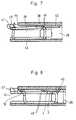
- Fig. 7 das distale Ende des Applikators und den verformten Clip nach Approximierung und Fixierung von (nicht dargestellen) Geweberändern;
- Fig. 8 das distale Ende des Applikators und den verformten und gegen Öffnen gesicherten Clip nach Approximierung und Fixierung von (nicht dargestelltem) Gewebe.
- Fig. 1 shows a clip according to the invention in side view and in plan view after placing in (not shown in) tissue;
- 2 shows the distal end of the applicator with a mounted clip in a top view;
- 3 shows the distal end of the applicator with an inserted clip in the initial form in a side view;
- 4 the side view of the distal end of the applicator with a deformed clip which can be inserted through a trocar sleeve;
- 5 shows the distal end of the applicator with a partially opened, ready-to-use clip in a side view;
- 6 shows the clip applicator in side view;
- 7 shows the distal end of the applicator and the deformed clip after approximation and fixation of tissue edges (not shown);
- 8 shows the distal end of the applicator and the deformed and secured clip against opening after approximation and fixation of (not shown) tissue.
Der erfindungsgemäße Clip ist in seiner endgültigen, im Gewebe gesetzten Form in Fig. 1 dargestellt. Er besteht aus einem Clipunterteil 1 und einem Clipoberteil 2, die durch ein biegeweiches Brückenteil 8 miteinander verbunden sind.The clip according to the invention is shown in its final form set in the tissue in FIG. 1. It consists of a
Der Clip kann insgesamt aus einem verbiegbaren Material, etwa aus einem geeigneten Edelstahldraht mit einheitlichem Durchmesser bestehen. Beim Setzen des Clip wird in diesem Fall das Brückenteil durch einen entsprechend konstruierten Applikator verformt, während das Clipunterteil und das Clipoberteil unverformt bleiben. Vorzugsweise ist jedoch der Querschnitt des Brückenteils 8 gegenüber den Querschnitten der übrigen Teile des Clip vermindert. Hierdurch wird erreicht, daß der Stift 9 beim Setzen des Clip ohne zu verbiegen eine hohe Kraft auf das Gewebe ausüben kann, während der Kraftaufwand für das Verbiegen des Brückenteils in Grenzen bleibt.The clip can consist of a bendable material, such as a suitable stainless steel wire with a uniform diameter. In this case, when the clip is placed, the bridge part is deformed by an appropriately designed applicator, while the lower clip part and the upper clip part remain undeformed. However, the cross section of the
Der erfindungsgemäße Clip hat eine Symmetrieebene. Das Clipunterteil 1 trägt an seinem freien Ende einen in der Symmetrieebene abgewinkelten Stift 9, der in eine Spitze 10 ausläuft. Das Clipoberteil 2 trägt an seinem freien Ende eine verrundete Protektornase 12. In der Nähe der Protektornase 12 ist das Clipoberteil 2 mit einem Durchbruch 11 versehen, der in der Symmetrieebene angeordnet ist. Die Längen des Clipunterteils 1 mit dem Stift 9, des biegeweichen Brückenteils 8 und des Clipoberteils 2 bis zum Durchbruch 11 sind so bemessen, daß der Stift 9 mit seiner Spitze 10 in den Durchbruch 11 eingreift, wenn das Clipoberteil 2 unter Verformung des Brückenteils 8 gegen das Clipunterteil 1 gedrückt wird.The clip according to the invention has a plane of symmetry. The lower part of the
Mit der Spitze 10 des Stiftes 9 wird das zu approximierende und zu fixierende Gewebe durchstochen und aufgeladen. Danach wird das Clipoberteil 2 durch Verbiegen des Brückenteils 8 so weit gegen den Stift 9 des Clipunterteils 1 gedrückt, bis die Spitze 10 durch den Durchbruch 11 greift. Der Querschnitt der Stiftspitze 10 und der Querschnitt des Durchbruchs wird einander entsprechend gewählt. Die einfachste Lösung besteht in einem kreisrunden Durchbruch 11 und einer kegel- oder pyramidenförmigen Spitze 10.With the
Vorzugsweise ist die Protektornase 12 in die selbe Richtung abgebogen wie der Stift 9. Hierdurch ist es möglich, den Clip gegen unbeabsichtigtes Öffnen zu sichern und gleichzeitig die Stiftspitze 10 so zu verwahren, daß weitere Verletzungen des fixierten Gewebes ausgeschlossen sind. Hierzu wird die aus dem Durchbruch 11 herausragende Stiftspitze 10 in Richtung auf die Protektornase 12 umgeknickt, so daß sie durch die abgebogene Protektornase 12 geschützt ist.The
Die Konstruktion eines geeigneten Applikators wird erleichtert, wenn der Brückenteil 8 des Clip einen geringeren Querschnitt aufweist und Versatzflächen 6, 7 im Clipoberteil 2 und Clipunterteil 1 an der Grenzfläche zwischen diesen Clipteilen und dein Brückenteil 8 vorgesehen werden. Vorteilhaft ist weiterhin, wenn in dem dem Brückenteil 8 benachbarten Bereich des Clipoberteils 2 beidseitig ein Zapfen 3 senkrecht zur Symmetrieebene ausgeformt ist. Besonders bevorzugt sind Zapfen mit einer Abschrägung 4 auf der dem Brückenteil 8 abgewandten Seite.The construction of a suitable applicator is made easier if the
Der erfindungsgemäße Clip kann aus Blech gestanzt und anschließend in die in Fig. 3 dargestellte Ausgangsform gebogen werden. Er besteht aus einem einzigen Teil, so daß kein Zusammenfügen von kleinen Einzelteilen notwendig ist. Bei entsprechender Materialwahl, z. B. einem biegeweichen Edelstahl, kann der Brückenteil mehrmals verformt werden, ohne daß ein Bruch auftritt. Der Clip kann so klein gefertigt werden, daß er durch eine der gebräuchlichen Trokarhülsen mit 5, 7 oder 10 mm gesetzt werden kann.The clip according to the invention can be punched out of sheet metal and then bent into the initial shape shown in FIG. 3. It consists of a single part, so that it is not necessary to assemble small individual parts. With appropriate choice of materials, e.g. B. a flexible stainless steel, the bridge part can be deformed several times without breaking. The clip can be made so small that it can be placed with one of the common 5, 7 or 10 mm trocar sleeves.
Die Konstruktion des an den erfindungsgemäßen Clip angepaßten Clipapplikators ist am besten aus den Fig. 3 und 6 ersichtlich. Wesentlich sind die folgenden Merkmale:
- a) ein Clipgreifer zum Ergreifen und Festhalten des biegeweichen Brückenteils 8 des Clip;
- b) ein Applikator-
Schaftrohr 39, das über einen Betätigungsgriff 13, 14 axial und senkrecht zum festgehaltenen biegeweichen Brückenteil 8 des Clip verschiebbar ist und dessenKopf 38 den Clip bei distalem Vorschub im Bereich des biegeweichen Brückenteils 8 in der Weise verformt,daß das Clipunterteil 1und das Clipoberteil 2 eine angenähert parallele Stellung einnehmen; - c)
zwei Öffnerzapfen 47im Applikatorkopf 38 und eine Anschlagstange 28im Clipgreifer 27, mit deren Hilfe bei proximaler Bewegung des Applikator-Schaftrohres 39das Clipoberteil 2 durch Verformen des biegeweichen Brückenteils 8 in eine annähernd senkrechte Stellung zum Clipunterteil 1 gebracht werden kann.
- a) a clip gripper for gripping and holding the
flexible bridge part 8 of the clip; - b) an
applicator shaft tube 39 which is displaceable axially and perpendicularly to the heldflexible bridge part 8 of the clip via anactuating handle head 38 deforms the clip in the region of theflexible bridge part 8 in the region of theflexible bridge part 8 in such a way that the lower part of theclip 1 and the clipupper part 2 assume an approximately parallel position; - c) two opening
pins 47 in theapplicator head 38 and astop rod 28 in theclip gripper 27, with the aid of which the clipupper part 2 can be brought into an approximately perpendicular position to the cliplower part 1 by deforming theflexible bridge part 8 when theapplicator shaft tube 39 is moved proximally.
Die in den Fig. 2 bis 8 gezeigte Ausführungsform des Clipapplikators ist für Einhandbedienung konzipiert. Sie erlaubt das Einbringen des Clip in der in Fig. 4 dargestellten Form durch eine dem Applikatorkopf 38 und dem Applikatorschaft 21 angepaßte, Trokarhülse von 5, 7 oder 10 mm.The embodiment of the clip applicator shown in FIGS. 2 to 8 is designed for one-hand operation. It allows the clip to be introduced in the form shown in FIG. 4 by means of a trocar sleeve of 5, 7 or 10 mm which is adapted to the
Durch einfache translatorische Bewegung des aus den Teilen 22, 38 und 39 bestehenden Schaftaußenteils relativ zum Schaftinnenteil 23 und zum Greifer 27 wird der Clip in der in Fig. 4 dargestellten Form gehalten und durch die Trokarhülse eingeführt, in die in Fig. 5 dargestellte Form geöffnet, nach Aufladen und Approximieren des Gewebes auf dem Stift 9 wie in Fig. 7 gezeigt geschlossen, wie in Fig. 8 dargestellt verriegelt und anschließend freigegeben. Das Schließen und Öffnen des Clip erfolgt unter Deformation des Scharnierbogens 48 (Fig. 4) im Brückenteil 8 durch das Kräftepaar zwischen der Greiferbacke 32 und der Anschlag- und Formungsrippe 44 beim Verschieben des Schaftrohres 39 in distaler Richtung (Schließen des Clip) bzw. durch das Kräftepaar zwischen der Anschlagstange 28 und den Öffnerzapfen 47 beim Zurückziehen des Schaftrohres 39 in proximale Richtung (Öffnen des Clip).By simply translating the shaft outer part consisting of the
Clipapplikator und Clip sind so aufeinander abgestimmt, daß entsprechend Fig. 3 beim Ladevorgang die Zapfenrücken 5 an den Zapfen 3 des Clipoberteiles 2 mit genügend Spiel über die Deckflächen 45 der Öffnerzapfen 47 im Applikatorkopf 38 bis zur Anschlag- und Formungsrippe 44 hinweg bewegt werden können.The clip applicator and clip are matched to one another such that, according to FIG. 3, the pin back 5 on the
Beim Öffnen und Schließen bewegt sich der Clip translatorisch etwa zwischen der in Fig. 5 gezeigten Stellung und dem Beginn der Nachformungsrippen 40 und 41 im Applikatorkopf 38 (siehe Fig. 3). Durch die gezeigte Konstruktion des Applikatorkopfes 38 und des Greifers 27 ist erreicht, daß in diesem Arbeitsbereich der Radius des Scharnierbogens 48 relativ groß bleibt und seine plastischen Verformungen erst nach unrealistisch vielen Arbeitsspielen zum Materialversagen führen.When opening and closing, the clip translates approximately between the position shown in FIG. 5 and the beginning of the
Beim Öffnen des Clip greift das oben beschriebene Kräftepaar am Brückenteil 8 und den beiden Zapfen 3 am Clipoberteil 2 an und führt so zu einer Radiusvergrößerung des Scharnierbogens 48.When the clip is opened, the pair of forces described above acts on the
Der Clip wird nach dem Greifen und Einziehen in den Applikatorkopf entsprechend Fig.3 durch Anlage an folgenden Einspann- oder Gleitflächen sicher gehalten und/oder geführt:
- Zwischen der distalen Stirnfläche der Anschlagstange 28 und
den Greiferbacken 32, - durch die
Versatzflächen 7am Clipunterteil 1 und die unteren Indexflächen 34 anden Greiferköpfen 29, - durch die Versatzflächen 6
am Clipoberteil 2 und die Indexflächen 35 anden Greiferköpfen 29, - durch die Führung des Clipunterteiles 1 sowohl seitlich in
der Nut 42 des Applikatorkopfes 38 als auch senkrecht dazu durch die Führung zwischen denUnterseiten der Greiferbacken 32 und der Grundfläche derNut 42, - durch den seitlichen Einschluß des Brückenteils 8 in
den Greiferbacken 29, - durch die (vorübergehende) seitliche Führung des Clipoberteiles 2 zwischen
den Öffnerzapfen 47 desApplikatorkopfes 38, - durch die gleitende Anlage des Clipoberteiles 2 an der Grundfläche der Führungsnut 51
im Applikatorkopf 38 und - durch die seitliche Führung der Clipzapfen 3
am Clipoberteil 2 inder Führungsnut 51 desApplikatorkopfes 38.
- Between the distal end face of the
stop rod 28 and thegripper jaws 32, - through the offset surfaces 7 on the
lower clip part 1 and the lower index surfaces 34 on the gripper heads 29, - through the offset surfaces 6 on the clip
upper part 2 and the index surfaces 35 on the gripper heads 29, - by guiding the
lower clip part 1 both laterally in thegroove 42 of theapplicator head 38 and perpendicularly to it by guiding between the undersides of thegripper jaws 32 and the base of thegroove 42, - by the lateral inclusion of the
bridge part 8 in thegripper jaws 29, - by the (temporary) lateral guidance of the clip
upper part 2 between the opening pins 47 of theapplicator head 38, - by the sliding contact of the clip
upper part 2 on the base of theguide groove 51 in theapplicator head 38 and - by the lateral guidance of the clip pins 3 on the
upper clip part 2 in theguide groove 51 of theapplicator head 38.
Das seitliche Ausweichen und Aufklaffen der Greiferbacken 29 in der Führungsnut 51 unter der Belastung der Clipumformungskräfte wird durch die Abstützung der Greiferbacken über die Führungsrippen 30 an den Seitenflächen der Führungsnut 51 verhindert.The lateral deflection and gaping of the
Der Clipgreifer 27 und damit auch der gefaßte Clip sind über das Schaftinnenteil 23 und das Handtellergriffteil 14 durch die Hand des Operateurs ergonomisch günstig und sicher dirigierbar. Das Schließen und Öffnen des Clip im Operationssitus durch Verschieben des Applikatorkopfes 38 und des Schaftrohres 39 bei Betätigen des Fingergriffteiles 13 führt nicht zu einer Dislocierung des Clip, die stets durch eine korrigierende Handbewegung des Operateurs auszugleichen wäre.The
Die Programmfolge beim Abarbeiten der oben aufgelisteten Systemfunktionen sowie die dazu erforderlichen Wege des Applikatorkopfes 38 relativ zum Clipgreifer 27 werden durch die Kulissenbahnen 17 im Antriebskopf 16 in Verbindung mit einer in sie eingreifenden Zunge am Federhebel 20 vorgegeben, der im Griffkopf 15 schwenkbar gelagert ist und der gegen den Druck der Flachfeder 50 zum Wechseln der Kulissenbahnen mit dem Daumen in Richtung Griffkopf 15 bewegt wird. Drei Arbeitsbereiche sind durch diese Programmechanik vorgegeben:The program sequence when executing the system functions listed above and the paths of the
Der Applikatorkkopf 38 wird relativ zum Greifer 27 durch Betätigen des Finger-Griffteiles 13 aus der in Fig.6 gezeichneten Stellung in die Position nach Fig.5 gebracht. Das Fingergriffteil 13 ist dann gegen distales Rückstellen in die Ausgangslage durch die Flachfedern 52 blockiert.The
Über das Fingergriffteil 13 kann der Applikatorkopf 38 relativ zum Greifer 27 zwischen zwei durch die Kulissenbahn festgelegten Anschlagpunkten hin und her bewegt werden. Dabei wird der Clip zum Aufladen von Geweberändern geöffnet (Fig.5) und geschlossen (Fig.4). Ein unbeabsichtigtes Freigeben oder Verriegeln des Clip ist nicht möglich.Via the
Nach dem Aufladen beider Geweberänder auf den Stift 9 des Clip wird wie oben beschrieben per Daumen der Federhebel 20 betätigt. Dadurch springt die Zunge am Federhebel 20 in den tieferliegenden zweiten Teil der Kulissenbahn 17. Durch das weitere jetzt mögliche Anziehen des Fingergriffteiles 13 wird unter den Nachformungsrippen 40 und 41 der Scharnierbogen 48 umgeformt, das Clipoberteil 2 tiefer gelegt (Fig.7 und 8), die Stiftspitze 10 auf die Protektornase 12 umgebogen und dadurch der Clip verriegelt (Fig.8). Bei Entlastung des Griffteiles 13 wird durch die Wirkung der Flachfedern 52 der Applikatorkopf 38 nach proximal zurückgezogen und der Clip mit den fixierten Geweberändern freigegeben.After loading both fabric edges onto the
Nach Lösen und Entfernen der beiden Rändelschrauben 18 und 24 kann der Applikatorschaft 21 einschließlich Applikatorkopf 38, Clipgreifer 27 und Antriebskopf 16 mit den Kulissenbahnen 17 gewechselt werden. Dabei ist es konstruktionsbedingt vorteilhaft, daß Applikator- und Antriebskopf gleichzeitig gewechselt werden und damit die Kulissenbahnen 17 stets den jeweiligen Clipabmessungen optimal angepaßt sind.After loosening and removing the two
Wie bei den bekannten Ligaturclips üblich, besteht auch das hier vorgeschlagene System aus dem Clip und dem zugehörigen Applikator.As is usual with the known ligature clips, the system proposed here also consists of the clip and the associated applicator.
Ebenso wird in Anlehnung an die Ligaturclips für die bestifteten Clips ein mehrteiliger Clipsatz mit verschieden großen und für den jeweiligen Anwendungsfall optimal bemessenen Clips mit den entsprechend angepaßten Applikatoren oder Applikatorköpfen vorgeschlagen.Likewise, based on the ligature clips for the pinned clips, a multi-part clip set with clips of different sizes and optimally dimensioned for the respective application with the appropriately adapted applicators or applicator heads is proposed.
Der hier gewählte Bedienungsgriff gestattet den Antrieb von Applikatoren mit 5 mm, 7 mm und 10 mm Schaftaußendurchmesser in geeigneten Trokarhülsen. Der Wechsel der Instrumentenschäfte 21 erfolgt durch Bedienung der beiden Rändelschrauben 18 und 24 im Antriebskopf 16 bzw. Griffkopf 15.The operating handle selected here allows applicators with 5 mm, 7 mm and 10 mm shaft outer diameter to be driven in suitable trocar sleeves. The
Der Applikator besteht aus drei Baugruppen:
Der Applikatorkopf 38mit dem Maul 26,den Führungsnuten und 51,den Nachformungsrippen 40 und 41 undden Öffnerzapfen 47 dient in Verbindungmit dem Clipgreifer 27 zur Aufnahme und Formung des Clip.- Der Handgriff besteht im wesentlichen aus
dem Handtellergriffteil 14, demüber den Bolzen 25 gelenkig mit ihm verbundenen Fingergriffteil 13,den Flachfedern 52 für die Griffrückstellung,dem Griffkopf 15 mitdem schwenkbaren Federhebel 20 und der Flachfeder 50 zu seiner Rückstellung.
Der Handgriff ist für Einhandbetrieb konzipiert. Er gestattet das Halten und Führen des Instruments, den Antrieb des Applikatorkopfes 38 und die Bedienung desFederhebeis 20 durch den Daumen des Operateurs bei der Abarbeitung des Applikationsprogrammes. Der Applikatorschaft 21mit dem Schaftrohr 39,dem Übergangsstück 22, dem mit demÜbergangsstück verbundenen Antriebskopf 16und dem Schaftinnenteil 23 ist in konstruktiv wählbarer Länge dieVerbindung zwischen Applikatorkopf 38 bzw.Clipgreifer 27 und dem Handgriff.Der Antriebskopf 16 enthält zwei Kulissennuten 17, die im Zusammenspiel mit einerZunge am Federhebel 20 ein sicheres Abarbeiten des Applikationsprogrammes ermöglichen. Die nebeneinander liegenden Kulissennuten 17 führen bei Bedienung des Applikatorgriffes die Zunge des Federhebels 20 auf drei verschiedenen Ebenen A, B und C, die in der Höhe um den Stufensprung s zueinander versetzt sind.
- The
applicator head 38 with themouth 26, theguide grooves post-forming ribs opening pin 47 is used in connection with theclip gripper 27 for receiving and shaping the clip. - The handle consists essentially of the
palm grip part 14, thefinger grip part 13 articulatedly connected to it via thepin 25, theflat springs 52 for the reset of the grip, thegrip head 15 with thepivotable spring lever 20 and theflat spring 50 for its return.
The handle is designed for one-handed operation. It allows the instrument to be held and guided, theapplicator head 38 to be driven, and thespring lever 20 to be operated by the operator's thumb when the application program is being processed. - The
applicator shaft 21 with theshaft tube 39, thetransition piece 22, thedrive head 16 connected to the transition piece and the shaftinner part 23 is the connection between theapplicator head 38 orclip gripper 27 and the handle in a constructively selectable length. Thedrive head 16 contains two slottedgrooves 17 which, in conjunction with a tongue on thespring lever 20, enable the application program to be processed reliably. The side-by-side link grooves 17 guide the tongue of thespring lever 20 on three different levels A, B and C when the applicator handle is operated, which are offset in height by the increment s.
Im folgenden wird das Applikationsprogramm des nach Fig.1 vorgeschlagenen Clip im Detail dargestellt.The application program of the clip proposed according to FIG. 1 is shown in detail below.
Der offene wie in Fig.3 gezeichnete Clip wird direkt aus einem geeignet geformten Magazin oder aus einer Pinzette vom Clipgreifer 27 übernommen. Bei proximaler Totpunktlage des Applikatorkopfes 38 ist, wie in Fig.6 dargestellt, der Clipgreifer 27 voll geöffnet. Der lichte Abstand zwischen den Greiferbacken 32 und den Greiferköpfen 29 ist in dieser Stellung maximal und durch die in diesem entspannten Zustand nach außen abgebogenen Flachfedern 31 vorgegeben.The open clip as drawn in FIG. 3 is taken over directly from a suitably shaped magazine or from tweezers by the
Wenn der Brückenteil 8 am distalen Ende der Anschlagstange 28 anliegt, kann der Applikatorkopf 38 distalwärts verschoben werden. Entsprechend dem zurückgelegten Weg des Applikatorkopfes 38 relativ zu den Greiferköpfen 29 wird der Clipgreifer 27 geschlossen.When the
Bei der Greiferbeladung aus einem angepaßten Magazin ist sichergestellt, daß bei diesem Vorgang der Clip relativ zu den Greiferköpfen 29 exakt so positioniert ist, daß der Brückenteil 8 genau zwischen den proximalen Flächen der Greiferbacken 32 und dem distalen Ende der Anschlagstange 28 liegt. Ferner ist dann gewährleistet, daß die Lage des Clip in den Greiferköpfen 29 sowohl durch die Führung der Versatzflächen 7 des Clipunterteils 1 an den Indexflächen 34 der Greiferköpfe 29 als auch durch die Führung der Versatzflächen 6 des Clipoberteils 2 an den Indexflächen 33 fixiert ist.When loading the gripper from an adapted magazine, it is ensured that during this process the clip is positioned exactly relative to the gripper heads 29 such that the
Da diese exakte Zuordnung von Clip und Clipgreifer bei Freihandbeladung nicht automatisch gesichert ist, muß in solchen Fällen besondere Sorgfalt angewandt werden.Since this exact assignment of clip and clip gripper is not automatically ensured when loading by freehand, special care must be taken in such cases.
Nach Positionierung des Clip im offenen Greifer 27 können die Greiferbacken 32, wie beschrieben, durch distal gerichteten Vorschub des Applikatorkopfes 38 geschlossen werden.After positioning the clip in the
Am Ende des Schließvorganges gleitet der Abschnitt des Clipoberteiles 2 zwischen den Zapfenrücken 5 und den Versatzflächen 6 sowie ein Teil des noch nicht geformten Scharnierbogens 48 des Brückenteils 8 durch den lichten Spalt zwischen den Öffnerzapfen 47 im Applikatorkopf 38 hindurch. Dabei ist konstruktiv ein hinreichender Abstand zwischen den Zapfenrücken 5 des noch gestreckten Clipoberteiles 2 und den Deckflächen 45 der Öffnerzapfen 47 gewährleistet.At the end of the closing process, the section of the
Die Führungsrippen 30 an den Greiferköpfen 29 spuren ebenfalls in die Führungsnut 51 ein und sichern jetzt durch Abstützung der Greiferköpfe 29 an den Wänden der Nut 51 den Greifer 27 gegen Aufklaffen unter Belastung.The
Die Führungsrippen 30 gleiten unter den Öffnerzapfen 47 im Applikatorkopf vorbei.The
Die Greiferköpfe 29 mit dem Clipunterteil 1 werden dabei in die untere Führungsnut 42 des Applikatorkopfes 38 eingezogen.The gripper heads 29 with the
Bis zur Berührung des Clipoberteiles 2 mit der Anschlag- und Formungsrippe 44 im Applikatorkopf 38 bleibt die Clipform, wie in Fig.3 dargestellt, unverändert.The clip shape, as shown in FIG. 3, remains unchanged until the clip
Durch weiteres Vorschieben des Applikatorkopfes 38 nach distal relativ zum Clipgreifer 27 wird die biegeweiche Brücke 8 im Bereich des Scharnierbogens 48 zwischen der Anschlag- und Formungsrippe 44 und den Greiferbacken 32 so verformt, daß das Clipoberteil 2 eine Schließbewegung in Richtung Clipunterteil 1 beginnt. Der Clip hat dann etwa die in Fig.5 gezeichnete Form. Das Clipoberteil 2 liegt aber noch an der Anschlag- und Formungsrippe 44.By pushing the
Während der bisher beschriebenen translatorischen Applikatorkopfbewegung ist die Zunge am Federhebel 20 zunächst auf einer ansteigenden Fläche der ersten Kulissenbahn 17a gegen die Federkraft des eigenen Schaftes von der Ausgangsebene A um 2 s auf das Niveau B gehoben worden. Fig.3 zeigt die entsprechende Clipposition im Applikatorkopf. Nach der oben beschriebenen ersten leichten Verformung des Brückenteiles 8 entsprechend der Fig.5 springt die Zunge am Federhebel 20 durch die Federwirkung des gespannten Hebelschaftes vom Niveau B um s auf die Ebene C der ersten Kulissenbahn 17 hinab.During the translatory applicator head movement described so far, the tongue on the
Damit ist der Ladevorgang des Applikators beendet. Das Fingergriffteil 13 ist über die Blockade des Antriebskopfes 16 gegen Rückstellung in die Ausgangslage gesichert. Eine unbeabsichtigte Freigabe des Clip ist ausgeschlossen.This completes the applicator loading process. The
Wird der Applikatorkopf 38 aus der Ladeendstellung relativ zum Greifer 27 weiter nach distal verschoben, so wird die gegen Ende des Ladevorganges eingeleitete Schließbewegung des Clip fortgesetzt. Der Clip gleitet weiter in die Führungsnuten 42 und 51 ein. Die Brücke 8 am Clipoberteil 2 wird dabei durch das Kräftepaar zwischen den Greiferbacken 32 und der Anschlag- und Formungsrippe 44 zum Scharnierbogen 48 ausgebildet.If the
Die seitlich aus dem Clipoberteil 2 vorspringenden Zapfen 3 treten durch den Spalt zwischen den Öffnerzapfen 47 und der Anschlag- und Verformungsrippe 44 hindurch in die Führungsnut 51, an deren Seitenflächen sie entlang gleiten und dadurch das Clipoberteil 2 seitlich abstützen. Eine zusätzliche Seitenführung des Clipoberteiles 2 ist im Laufe des Schließvorganges durch sein Eintauchen zwischen die Öffnerzapfen 47 im Applikatorkopf 38 gegeben (Fig.4).The
Die in Fig.4 gezeichnete Form des Clip, die auch bei weiterer Verschiebung des Applikatorkopfes bis zur Berührung mit den Anlaufflächen 49 der Nachformungsrippen 40 und 41 unverändert bleibt, erlaubt das Einbringen des Clip und des Applikatorkopfes 38 durch eine entsprechende Trokarhülse in den Operationssitus, da die Stirnsilhouette des Clip jetzt an keiner Stelle die Außenkontur des Applikatorkopfes überragt.The shape of the clip shown in FIG. 4, which remains unchanged even when the applicator head is moved further until it comes into contact with the contact surfaces 49 of the
Der distale Vorschubweg des Applikatorkopfes 38 relativ zum Clipgreifer 27 wird durch den Anschlag der Federhebelzunge am proximalen Ende der ersten Kulissenbahn 17 auf der Ebene C im Antriebskopf 16 begrenzt. Ein unbeabsichtigtes Verriegeln des Clip bei Unterfahren der Nachformungsrippen 40 und 41 ist damit ausgeschlossen. Solange der Applikatorkopf 38 relativ zum Clipgreifer 27 in einem Bereich bewegt wird, der durch den distalen und proximalen Anschlag auf der Ebene C der ersten Kulissenbahn 17 begrenzt ist, bleibt der Clip gegen unbeabsichtigtes Freigeben und Verriegeln gesichert.The distal feed path of the
Zum Greifen und Aufladen des ersten Geweberandes muß der Clip im Operationsfeld geöffnet werden. Dazu wird das Fingergriffteil 13 entlastet und durch die entsprechend bemessenen Flachfedern 52 zwischen den Griffteilen zurückbewegt. Der Applikatorkopf 38 wird dadurch nach proximal verschoben.The clip must be opened in the surgical field to grip and load the first tissue edge. For this purpose, the
Wenn sich die Flächen der Abschrägung 4 an den Zapfen 3 des Clipoberteiles 2 und die Flächen 46 an den Öffnerzapfen 47 berühren, entsteht durch Zerlegung der parallel zur Applikatorachse wirkenden Schubkraft auf die Zapfen 3 am Clipoberteil 2 eine Kraftkomponente, die den Clip, wie in Fig.5 dargestellt, durch teilweise Streckung des Scharnierbogens 48 öffnet.If the surfaces of the
Die Spitze 10 des Stiftes 9 am Clipunterteil 1 wird nahe dem Inzisionsrand auf die Außenfläche (die Fläche, die ohne Inzision zum Applikator zeigen würde) des Gewebes gesetzt und durch axiale Bewegung des Stiftes versucht, das Gewebe zu durchstechen. Unterstützt wird dieser Versuch durch vorsichtige Längsbewegung des Applikators nach proximal. Dabei entsteht an der zur Clipbrücke hin geneigten Stiftspitze 10 eine zusätzliche Kraftkomponente in Richtung der Stiftachse.The
Ist ein Durchstich infolge zu großer Gewebewiderstände auf diese Weise nicht möglich, so wird durch Anziehen des Fingergriffteiles 13 der Applikatorkopf 38 relativ zum Clipgreifer 27 distalwärts bewegt und dadurch der Clip wie oben beschrieben geschlossen.If a puncture due to excessive tissue resistance is not possible in this way, the
Dabei wird der zwischen der Stiftspitze 10 und dem Durchbruch 11 im Clipoberteil 2 liegende Gewebequerschnitt wegen des minimierten elastischen Ausweichens und wegen der Gegenhaltekraft des Oberteiles leichter durchstochen und der Geweberand auf die Spitze aufgeladen.The tissue cross section lying between the
Der im lichten Querschnitt des Clip liegende Geweberand wandert beim Schließen des Clip in das Maul 26 des Applikatorkopfes 38.The fabric edge lying in the clear cross section of the clip migrates into the
Nach erneutem Öffnen des Clip wird der zweite Geweberand von der Inzisionsfläche oder der Geweberückseite her wie beschrieben durchstochen und aufgeladen. Muß zur Unterstützung des Durchstichs der Clip erneut geschlossen werden, so kann das Fingergriffteil 13 bis zum Anschlag der Federhebelzunge am proximalen Ende der ersten Kulissenbahn 17 auf der Ebene C angezogen werden.After opening the clip again, the second tissue margin is pierced and charged from the incision surface or the tissue back as described. If the clip has to be closed again to support the puncture, this can Finger
In dieser Griff- und Applikatorkopfstellung liegt die Außenseite des Scharnierbogens 48 dicht vor den Anlaufflächen 49 der Nachformungsrippen 40 und 41.In this handle and applicator head position, the outside of the
Damit ist das Aufladen und Fixieren der Geweberänder relativ zueinander beendet. Nun muß der mit biegeweicher Brücke 8 konzipierte Clip verriegelt werden, da er aufgrund seiner Konstruktion ohne diese Sicherung nicht fähig ist, wie ein biegesteifer Ligaturclip die Gewebefixierungskräfte aufzunehmen.The loading and fixing of the tissue edges relative to one another is thus ended. Now the clip designed with a
Zur formschlüssigen Verriegelung des beladenen Clip wird bei geschlossenem Clip nach Fig.4 mit dem Daumen der griffhaltenden Hand der Federhebel 20 gegen den Widerstand der Flachfeder 50 zum Griffkopf 15 hin gedrückt.For the positive locking of the loaded clip, the
Dadurch fällt die Zunge des Federhebels 20 um s auf das Niveau A in der zweiten Kulissenbahn 17 zurück. Nach diesem kurzen einmaligen Druck auf den Federhebel 20 ist die Zunge in der Kulissenbahn 17 gefangen. Sie gleitet am Stufensprung zwischen den Nuten 17 entlang und hindert dadurch den Federhebel 20 vor der Freigabe des Clip an der Rückstellung.As a result, the tongue of the
Wird das Fingergriffteil 13 jetzt weiter angezogen und damit der Applikatorkopf 38 relativ zum Clipgreifer 27 weiter nach distal verschoben, so berührt zunächst der Scharnierbogen 48 des Clip die schrägen Anlaufflächen 49 der Nachformungsrippen 40 bzw. 41.If the
Wenn die auftreibenden Gewebekräfte am Clipverschluß nicht zu groß sind, bewegt sich das distale Ende des Clipoberteiles 2, wie in Fig.7 dargestellt, unter Deformation des Scharnierbogens 48 weiter in Richtung Clipunterteil 1, bis sich der untere Rand des Durchbruches 11 auf die schrägen Kanten der Stiftspitze 10 aufsetzt.If the floating tissue forces on the clip closure are not too great, the distal end of the clip
Unter weiterem distalen Vorschub des Applikatorkopfes 38 wird der Scharnierbogen 48 unter die Nachformungsrippen 40 bzw. 41 gedrückt und dadurch das Clipoberteil 2 in die in Fig.8 dargestellte Form gebracht.With further distal advancement of the
Dieser Vorgang hat eine distale Verschiebung des Durchbruchs 11 im Clipoberteil 2 relativ zum Brückenteil 8 zur Folge. Deshalb wandert auch die im Durchbruch 11 gefesselte Stiftspitze 10, wie in Fig.8 gezeichnet, distalwärts aus.This process results in a distal displacement of the
Während der Umformung des Scharnierbogens 48 wird auch die Stiftspitze 10 an der Anschlag- und Formungsrippe 44 umgebogen und gleitet in die Führungsnut 51.During the shaping of the
Die Protektornase 12 am Clipoberteil 2 wird je nach Dicke und elastischer Gegenkraft des Gewebes im Clip mehr oder weniger gerade gebogen. Die Rückstellkräfte der Protektornase 12 nach der Verformung sichern durch das Abstützen des Lochrandes im Clipoberteil 2 auf den Kanten der Stiftspitze 10 das Aufliegen der Spitze auf der Protektornase und damit das Lagergewebe des Clip gegen Verletzung.The
Die bisher beschriebenen Verformungen werden unter Verschiebung des Applikatorkopfes 38 und des Schaftrohres 39 bis zum Anschlag der Zunge des Federhebels 20 am proximalen Ende der Kulissennut 17 erzeugt.The deformations described so far are produced by displacing the
Das Clipoberteil 2 ist durch den Umformungs- und Schließvorgang aus dem Grund der Führungsnut 51, in dem durch translatorisches Gleiten das Öffnen und Schließen des Clip realisiert wurde, weiter zur Achse des Applikatormaules 26 versetzt worden (Fig.8). Die Zapfen 3 am Clipoberteil 2 liegen jetzt, wie in Fig.8 dargestellt, in einer Ebene unterhalb der Öffnerzapfen 47. Wird der Applikatorkopf 38 nach proximal zurückgezogen, so gleiten die Zapfen 3 am Clipoberteil 2 unter den Öffnerzapfen 47 hindurch.The upper part of the
Nach weiterem Zurückziehen des Applikatorkopfes 38 öffnen die Flachfedern 31 die die Cllpbrücke 8 umfassenden Greiferköpfe 29, und die Greiferbacken 32 geben den entsprechend Fig.1 geformten Clip mit den eingeschlossenen Geweberändern frei.After the
Gegen Ende des Freigabevorganges springt durch den Druck der Flachfelder 50 die Zunge des Federhebeis 20 auf dem Niveau A von der zweiten Kulissenbahn 17 in die erste Kulissenbahn 17 zurück. Damit befindet sich der Federhebel 20 wieder in der Ausgangsstellung.Towards the end of the release process, the tongue of the spring hoist 20 jumps back on level A from the
Der Applikator kann mit vorstehendem Greifer 27 durch die Trokarhülse aus dem Operationssitus entfernt und sofort mit dem nächsten Clip beladen werden.

Claims (6)
- Clip for surgical use, having the following features:a) the clip comprises a lower clip portion (1) and an upper clip portion (2), which portionsb) are interconnected by a flexible bridge member (8);c) the lower clip portion (1), the upper clip portion (2) and the flexible bridge member (8) lie in a plane of symmetry;d) the lower clip portion (1) carries, at its free end, a pin (9) which is bent-over in the plane of symmetry and is provided with a point (10);e) the upper clip portion (2) carries, at its free end, a rounded protective projection member (12),f) which communicates with an opening (11) disposed in the plane of symmetry;g) the length of the lower clip portion (1), including the length of the pin (9), the length of the upper clip portion (2) as far as the opening (11), and the length of the flexible bridge member (8) are selected so that the point (10) of the pin (9) is insertable into the opening (11) as a result of bending the upper clip portion (2) whilst deforming the flexible bridge member (8) in a direction towards the lower clip portion (1),characterised by the following features:h) the pin (9) tapers towards the point (10), the point having a conical or pyramid-shaped configuration;i) the length of the flexible bridge member (8) is dimensioned so that, for the closure of the clip, it is deformable in the plane of symmetry at two different locations at an approximate right angle in such a manner that the closed clip approximately assumes the shape of a rectangle, the sides of which are represented by the flexible bridge member (8), the lower clip portion (1), the pin (9) and the upper clip portion (2).
- Clip according to claim 1, characterised in that the protective projection member (12) is bent-over into the same direction as the pin (9).
- Clip according to claim 1 or 2, characterised in that the cross-section of the felexible bridge member (8) is smaller than the cross-sections of the lower clip portion (1) and the upper clip portion (2).
- Clip according to claim 3, characterised in that the interfaces between the lower clip portion (1), the upper clip portion (2) and the flexible bridge member (8) are configured as offset faces (6, 7).
- Clip according to one of claims 1 to 4, characterised in that the upper clip portion (2) carries, in its region abutting against the flexible bridge member (8), two pins (3) which are symmetrically disposed perpendicular to the plane of symmetry.
- Clip applicator having a clip according to one of claims 1 to 5, characterised bya) a clip gripping device (27) for gripping and retaining the flexible bridge member (8) of the clip;b) an applicator shank tube (39), which is displaceable, via an operating handle (13, 14), axially and perpendicularly to the retained, flexible bridge member (8) of the clip, and the head (38) of which tube deforms the clip in the event of distal advancement in the region of the flexible bridge member (8) in such a manner that the lower clip portion (1) and the upper clip portion (2) assume an approximately parallel position, the point (10) of the pin (9) piercing the opening (11);c) two opening pins (47) in the applicator head (38) and one stop rod (28) in the clip gripping device (27), by means of which component parts the upper clip portion (2) can be brought into an approximately perpendicular position relative to the lower clip portion (1) by deforming the flexible bridge member (8) in the event of a proximal movement of the applicator shank tube (39).
Applications Claiming Priority (3)
| Application Number | Priority Date | Filing Date | Title |
|---|---|---|---|
| DE4230102ADE4230102C2 (en) | 1992-09-09 | 1992-09-09 | Clip for use in surgery and clip applicator |
| DE4230102 | 1992-09-09 | ||
| PCT/EP1993/001929WO1994005219A1 (en) | 1992-09-09 | 1993-07-21 | Clip for surgical use and clip applicator |
Publications (2)
| Publication Number | Publication Date |
|---|---|
| EP0659060A1 EP0659060A1 (en) | 1995-06-28 |
| EP0659060B1true EP0659060B1 (en) | 1997-01-15 |
Family
ID=6467571
Family Applications (1)
| Application Number | Title | Priority Date | Filing Date |
|---|---|---|---|
| EP93915967AExpired - LifetimeEP0659060B1 (en) | 1992-09-09 | 1993-07-21 | Clip for surgical use and clip applicator |
Country Status (6)
| Country | Link |
|---|---|
| US (1) | US5522823A (en) |
| EP (1) | EP0659060B1 (en) |
| JP (1) | JP2589058B2 (en) |
| AT (1) | ATE147611T1 (en) |
| DE (1) | DE4230102C2 (en) |
| WO (1) | WO1994005219A1 (en) |
Families Citing this family (69)
| Publication number | Priority date | Publication date | Assignee | Title |
|---|---|---|---|---|
| US6464710B1 (en)* | 1995-03-06 | 2002-10-15 | Cook Urological Incorporated | Releasable, surgical clamp |
| US5741274A (en)* | 1995-12-22 | 1998-04-21 | Cardio Vascular Concepts, Inc. | Method and apparatus for laparoscopically reinforcing vascular stent-grafts |
| DE19711288B4 (en)* | 1997-03-18 | 2004-11-04 | Helmut Dipl.-Ing. Wurster | Applicator to hold and close a surgical clip |
| US5928251A (en)* | 1997-09-18 | 1999-07-27 | United States Surgical Corporation | Occlusion clamp and occlusion clamp applicator |
| WO2000076432A1 (en)* | 1999-06-10 | 2000-12-21 | Mark Stafford Carey | Clip and applicator for tubal ligation |
| GB9916484D0 (en)* | 1999-07-15 | 1999-09-15 | Femcare Ltd | Surgical clip |
| US6855154B2 (en) | 2000-08-11 | 2005-02-15 | University Of Louisville Research Foundation, Inc. | Endovascular aneurysm treatment device and method |
| US20020082621A1 (en) | 2000-09-22 | 2002-06-27 | Schurr Marc O. | Methods and devices for folding and securing tissue |
| US7727246B2 (en)* | 2000-12-06 | 2010-06-01 | Ethicon Endo-Surgery, Inc. | Methods for endoluminal treatment |
| US8062314B2 (en)* | 2000-12-06 | 2011-11-22 | Ethicon Endo-Surgery, Inc. | Methods for the endoluminal treatment of gastroesophageal reflux disease (GERD) |
| US20020138086A1 (en)* | 2000-12-06 | 2002-09-26 | Robert Sixto | Surgical clips particularly useful in the endoluminal treatment of gastroesophageal reflux disease (GERD) |
| US20020068945A1 (en)* | 2000-12-06 | 2002-06-06 | Robert Sixto | Surgical clips particularly useful in the endoluminal treatment of gastroesophageal reflux disease (GERD) |
| US6716226B2 (en) | 2001-06-25 | 2004-04-06 | Inscope Development, Llc | Surgical clip |
| US7232445B2 (en)* | 2000-12-06 | 2007-06-19 | Id, Llc | Apparatus for the endoluminal treatment of gastroesophageal reflux disease (GERD) |
| US6808491B2 (en) | 2001-05-21 | 2004-10-26 | Syntheon, Llc | Methods and apparatus for on-endoscope instruments having end effectors and combinations of on-endoscope and through-endoscope instruments |
| US7727248B2 (en)* | 2001-06-25 | 2010-06-01 | Ethicon Endo-Surgery, Inc. | Surgical clip |
| US7331968B2 (en) | 2004-06-14 | 2008-02-19 | Ethicon Endo-Surgery, Inc. | Endoscopic clip applier with threaded clip |
| JP2005522259A (en)* | 2002-04-10 | 2005-07-28 | タイコ ヘルスケア グループ エルピー | Surgical clip applier with high torque jaws |
| EP1572010A2 (en)* | 2002-12-16 | 2005-09-14 | Edrich Vascular Devices, Inc. | Vascular suturing clip |
| EP1608272B1 (en) | 2003-03-11 | 2017-01-25 | Covidien LP | Clip applying apparatus with angled jaw |
| US20040193188A1 (en)* | 2003-03-25 | 2004-09-30 | Inscope Development, Llc | Laminated surgical clip |
| US20040193189A1 (en)* | 2003-03-25 | 2004-09-30 | Kortenbach Juergen A. | Passive surgical clip |
| US7105000B2 (en)* | 2003-03-25 | 2006-09-12 | Ethicon Endo-Surgery, Inc. | Surgical jaw assembly with increased mechanical advantage |
| WO2006034403A2 (en) | 2004-09-23 | 2006-03-30 | Tyco Healthcare Group, Lp | Clip applying apparatus and ligation clip |
| US7819886B2 (en) | 2004-10-08 | 2010-10-26 | Tyco Healthcare Group Lp | Endoscopic surgical clip applier |
| US8409222B2 (en) | 2004-10-08 | 2013-04-02 | Covidien Lp | Endoscopic surgical clip applier |
| CA2809110A1 (en) | 2004-10-08 | 2006-04-20 | Tyco Healthcare Group Lp | Apparatus for applying surgical clips |
| EP2641548B1 (en) | 2004-10-08 | 2015-08-19 | Covidien LP | Endoscopic surgical clip applier |
| US20060180633A1 (en)* | 2005-02-17 | 2006-08-17 | Tyco Healthcare Group, Lp | Surgical staple |
| US20060224170A1 (en)* | 2005-03-30 | 2006-10-05 | Michael Duff | Surgical marker clip and method for cholangiography |
| USD625009S1 (en) | 2006-03-24 | 2010-10-05 | Tyco Healthcare Group Lp | Surgical clip applier |
| USD629101S1 (en) | 2006-03-24 | 2010-12-14 | Tyco Healthcare Group Lp | Surgical clip applier |
| CA2605135C (en) | 2006-10-17 | 2014-12-30 | Tyco Healthcare Group Lp | Apparatus for applying surgical clips |
| EP2157920B1 (en) | 2007-03-26 | 2017-09-27 | Covidien LP | Endoscopic surgical clip applier |
| CN102327136B (en) | 2007-04-11 | 2014-04-23 | 柯惠Lp公司 | Surgical clip applier |
| DE102007060057A1 (en)* | 2007-12-13 | 2009-06-18 | Robert Bosch Gmbh | Hand tool |
| US8465502B2 (en) | 2008-08-25 | 2013-06-18 | Covidien Lp | Surgical clip applier and method of assembly |
| US8056565B2 (en) | 2008-08-25 | 2011-11-15 | Tyco Healthcare Group Lp | Surgical clip applier and method of assembly |
| US9358015B2 (en) | 2008-08-29 | 2016-06-07 | Covidien Lp | Endoscopic surgical clip applier with wedge plate |
| US8267944B2 (en) | 2008-08-29 | 2012-09-18 | Tyco Healthcare Group Lp | Endoscopic surgical clip applier with lock out |
| US8409223B2 (en) | 2008-08-29 | 2013-04-02 | Covidien Lp | Endoscopic surgical clip applier with clip retention |
| US8585717B2 (en) | 2008-08-29 | 2013-11-19 | Covidien Lp | Single stroke endoscopic surgical clip applier |
| US8734469B2 (en) | 2009-10-13 | 2014-05-27 | Covidien Lp | Suture clip applier |
| US9186136B2 (en) | 2009-12-09 | 2015-11-17 | Covidien Lp | Surgical clip applier |
| US8545486B2 (en) | 2009-12-15 | 2013-10-01 | Covidien Lp | Surgical clip applier |
| US8403945B2 (en) | 2010-02-25 | 2013-03-26 | Covidien Lp | Articulating endoscopic surgical clip applier |
| US8403946B2 (en) | 2010-07-28 | 2013-03-26 | Covidien Lp | Articulating clip applier cartridge |
| US8968337B2 (en) | 2010-07-28 | 2015-03-03 | Covidien Lp | Articulating clip applier |
| FR2964553B1 (en)* | 2010-09-09 | 2012-08-31 | Arnold Louis Henri Ferlin | SURGICAL TREATMENT SYSTEM FOR REALIZING ANASTOMOSIS BETWEEN THE BLADDER AND THE URETRE |
| US9011464B2 (en) | 2010-11-02 | 2015-04-21 | Covidien Lp | Self-centering clip and jaw |
| US9186153B2 (en) | 2011-01-31 | 2015-11-17 | Covidien Lp | Locking cam driver and jaw assembly for clip applier |
| US10398444B2 (en) | 2011-03-30 | 2019-09-03 | Noha, Llc | Advanced endovascular clip and method of using same |
| US10028745B2 (en) | 2011-03-30 | 2018-07-24 | Noha, Llc | Advanced endovascular clip and method of using same |
| US9775623B2 (en) | 2011-04-29 | 2017-10-03 | Covidien Lp | Surgical clip applier including clip relief feature |
| US9364239B2 (en) | 2011-12-19 | 2016-06-14 | Covidien Lp | Jaw closure mechanism for a surgical clip applier |
| US9364216B2 (en) | 2011-12-29 | 2016-06-14 | Covidien Lp | Surgical clip applier with integrated clip counter |
| US9408610B2 (en) | 2012-05-04 | 2016-08-09 | Covidien Lp | Surgical clip applier with dissector |
| US9532787B2 (en) | 2012-05-31 | 2017-01-03 | Covidien Lp | Endoscopic clip applier |
| EP2882354B1 (en)* | 2012-08-09 | 2020-09-23 | Advanced Bariatric Technology, LLC | Polymer overmolded bariatric clamp |
| US9563266B2 (en)* | 2012-09-27 | 2017-02-07 | Immersivetouch, Inc. | Haptic augmented and virtual reality system for simulation of surgical procedures |
| US10108266B2 (en) | 2012-09-27 | 2018-10-23 | The Board Of Trustees Of The University Of Illinois | Haptic augmented and virtual reality system for simulation of surgical procedures |
| US9113892B2 (en) | 2013-01-08 | 2015-08-25 | Covidien Lp | Surgical clip applier |
| US9750500B2 (en) | 2013-01-18 | 2017-09-05 | Covidien Lp | Surgical clip applier |
| US10863992B2 (en) | 2017-08-08 | 2020-12-15 | Covidien Lp | Endoscopic surgical clip applier |
| US10786273B2 (en) | 2018-07-13 | 2020-09-29 | Covidien Lp | Rotation knob assemblies for handle assemblies |
| US11259887B2 (en) | 2018-08-10 | 2022-03-01 | Covidien Lp | Feedback mechanisms for handle assemblies |
| US11033256B2 (en) | 2018-08-13 | 2021-06-15 | Covidien Lp | Linkage assembly for reusable surgical handle assemblies |
| US11253267B2 (en) | 2018-08-13 | 2022-02-22 | Covidien Lp | Friction reduction mechanisms for handle assemblies |
| JP7338851B2 (en)* | 2019-06-07 | 2023-09-05 | 株式会社Tjmデザイン | Goods carrying clip |
Family Cites Families (19)
| Publication number | Priority date | Publication date | Assignee | Title |
|---|---|---|---|---|
| DE8329725U1 (en)* | 1984-02-02 | Frydrych, Andreas, Dr.med., 6000 Frankfurt | Microclips for medical purposes made of elastically deformable material | |
| GB972731A (en)* | 1961-05-31 | 1964-10-14 | Mihaly Gerendas | Improvements in or relating to artery clamps |
| DE2402677A1 (en)* | 1974-01-21 | 1975-07-24 | Technibiotics | Surgical blood-vessel clamp - has elastic sleeve with hole to receive flexible ligature looped about blood vessel |
| US4212303A (en)* | 1978-07-17 | 1980-07-15 | Hollister Incorporated | Umbilical cord clamp |
| US4390019A (en)* | 1979-02-28 | 1983-06-28 | Leveen Harry H | Blood vessel clamp |
| DE2917783C2 (en)* | 1979-05-03 | 1982-07-01 | Richard Wolf Gmbh, 7134 Knittlingen | Forceps for applying a clip to a fallopian tube |
| GB2054384B (en)* | 1979-07-27 | 1983-09-07 | Trewavis Surgical Scient Inst | Clip applicator |
| US4498476A (en)* | 1981-08-27 | 1985-02-12 | Ethicon, Inc. | Non-metallic, bio-compatible hemostatic clips with interlocking latch means |
| US4449531A (en)* | 1981-08-27 | 1984-05-22 | Ethicon, Inc. | Non-metallic, bio-compatible hemostatic clips with interlocking latch means |
| DE3139488C2 (en)* | 1981-10-03 | 1984-08-16 | Aesculap-Werke Ag Vormals Jetter & Scheerer, 7200 Tuttlingen | Aneurysm clip |
| US4487204A (en)* | 1981-10-14 | 1984-12-11 | Nomel | Device for applying haemostatic clips |
| US4556060A (en)* | 1982-09-30 | 1985-12-03 | Metatech Corporation | Surgical clip |
| US4932955A (en)* | 1984-06-29 | 1990-06-12 | Baxter International Inc. | Clip |
| JPH0657218B2 (en)* | 1985-05-10 | 1994-08-03 | エチコン・インコ−ポレ−テツド | Ligation clip and clip application device |
| DE8914582U1 (en)* | 1989-12-12 | 1990-02-08 | Hubbes, Hilmar, 4937 Lage | Wound clip, especially surgical microclip |
| DE4015562C2 (en)* | 1990-05-15 | 1996-12-19 | Storz Karl | Forceps for putting on hemostatic clips |
| DE9017894U1 (en)* | 1990-08-03 | 1992-10-29 | Peter Lazic Mikroinstrumente GmbH, 7200 Tuttlingen | Clip application pliers |
| CA2104345A1 (en)* | 1992-09-02 | 1994-03-03 | David T. Green | Surgical clamp apparatus |
| US5462558A (en)* | 1994-08-29 | 1995-10-31 | United States Surgical Corporation | Suture clip applier |
- 1992
- 1992-09-09DEDE4230102Apatent/DE4230102C2/ennot_activeExpired - Fee Related
- 1993
- 1993-07-21EPEP93915967Apatent/EP0659060B1/ennot_activeExpired - Lifetime
- 1993-07-21ATAT93915967Tpatent/ATE147611T1/ennot_activeIP Right Cessation
- 1993-07-21JPJP6506779Apatent/JP2589058B2/ennot_activeExpired - Lifetime
- 1993-07-21WOPCT/EP1993/001929patent/WO1994005219A1/enactiveIP Right Grant
- 1994
- 1994-12-09USUS08/352,904patent/US5522823A/ennot_activeExpired - Fee Related
Also Published As
| Publication number | Publication date |
|---|---|
| US5522823A (en) | 1996-06-04 |
| JPH08502671A (en) | 1996-03-26 |
| DE4230102C2 (en) | 1994-08-04 |
| WO1994005219A1 (en) | 1994-03-17 |
| ATE147611T1 (en) | 1997-02-15 |
| EP0659060A1 (en) | 1995-06-28 |
| DE4230102A1 (en) | 1994-03-10 |
| JP2589058B2 (en) | 1997-03-12 |
Similar Documents
| Publication | Publication Date | Title |
|---|---|---|
| EP0659060B1 (en) | Clip for surgical use and clip applicator | |
| EP0684012B1 (en) | Thread for applying a surgical suture, combination of a transfer holder and the thread and combination of a surgical suturing instrument and the thread | |
| DE3390238C2 (en) | Instrument for attaching a surgical clip to body tissue | |
| DE19964081B4 (en) | Stripe-type implant and surgical gripping instrument | |
| DE3126578C2 (en) | Two-legged suturing instrument for use in surgery | |
| EP2335609B1 (en) | Surgical instrument | |
| DE69201626T2 (en) | Surgical clip magazine. | |
| DE3249116C2 (en) | Surgical instrument | |
| DE60304007T2 (en) | Surgical clamp and fixation device for it | |
| DE69733648T2 (en) | METHOD FOR ATTACHING DEFORMABLE TERMINALS | |
| EP0768838B1 (en) | Surgical suturing device | |
| DE69825249T2 (en) | APPLICATOR FOR MOUNTING A SURGICAL CLIP IN TISSUE | |
| DE3311347C2 (en) | Surgical staple extractor | |
| EP0469245A1 (en) | Clip applicator for ligature clips | |
| DE102009010101A1 (en) | Medical instrument for grasping surgical sutures | |
| DE4400409A1 (en) | Microsurgical instrument | |
| WO2015165822A1 (en) | Jaw for a surgical tubular shaft instrument | |
| DE69410452T2 (en) | SURGICAL NEEDLE HOLDER | |
| EP3773241A1 (en) | Medical instrument | |
| DE1810806A1 (en) | Surgical needle holder with increasing translation and hand-friendly grip technique | |
| WO1993005717A1 (en) | Surgical instrument | |
| DE69304601T2 (en) | Coupling device for surgical instruments | |
| DE19646326C2 (en) | Medical forceps | |
| DE29716753U1 (en) | Surgical tunneling instrument | |
| DE2419580C3 (en) | Surgical device for ligating tubular organic structures in deep body cavities |
Legal Events
| Date | Code | Title | Description |
|---|---|---|---|
| PUAI | Public reference made under article 153(3) epc to a published international application that has entered the european phase | Free format text:ORIGINAL CODE: 0009012 | |
| 17P | Request for examination filed | Effective date:19941004 | |
| AK | Designated contracting states | Kind code of ref document:A1 Designated state(s):AT BE CH FR GB LI | |
| GRAG | Despatch of communication of intention to grant | Free format text:ORIGINAL CODE: EPIDOS AGRA | |
| GRAH | Despatch of communication of intention to grant a patent | Free format text:ORIGINAL CODE: EPIDOS IGRA | |
| 17Q | First examination report despatched | Effective date:19960619 | |
| GRAH | Despatch of communication of intention to grant a patent | Free format text:ORIGINAL CODE: EPIDOS IGRA | |
| RAP1 | Party data changed (applicant data changed or rights of an application transferred) | Owner name:FORSCHUNGSZENTRUM KARLSRUHE GMBH | |
| GRAA | (expected) grant | Free format text:ORIGINAL CODE: 0009210 | |
| AK | Designated contracting states | Kind code of ref document:B1 Designated state(s):AT BE CH FR GB LI | |
| REF | Corresponds to: | Ref document number:147611 Country of ref document:AT Date of ref document:19970215 Kind code of ref document:T | |
| REG | Reference to a national code | Ref country code:CH Ref legal event code:NV Representative=s name:ROTTMANN, ZIMMERMANN + PARTNER AG Ref country code:CH Ref legal event code:EP | |
| ET | Fr: translation filed | ||
| GBT | Gb: translation of ep patent filed (gb section 77(6)(a)/1977) | Effective date:19970320 | |
| PLBE | No opposition filed within time limit | Free format text:ORIGINAL CODE: 0009261 | |
| STAA | Information on the status of an ep patent application or granted ep patent | Free format text:STATUS: NO OPPOSITION FILED WITHIN TIME LIMIT | |
| 26N | No opposition filed | ||
| REG | Reference to a national code | Ref country code:GB Ref legal event code:IF02 | |
| PGFP | Annual fee paid to national office [announced via postgrant information from national office to epo] | Ref country code:CH Payment date:20040629 Year of fee payment:12 | |
| PGFP | Annual fee paid to national office [announced via postgrant information from national office to epo] | Ref country code:BE Payment date:20040705 Year of fee payment:12 | |
| PGFP | Annual fee paid to national office [announced via postgrant information from national office to epo] | Ref country code:GB Payment date:20040713 Year of fee payment:12 | |
| PGFP | Annual fee paid to national office [announced via postgrant information from national office to epo] | Ref country code:AT Payment date:20040728 Year of fee payment:12 | |
| PGFP | Annual fee paid to national office [announced via postgrant information from national office to epo] | Ref country code:FR Payment date:20040730 Year of fee payment:12 | |
| PG25 | Lapsed in a contracting state [announced via postgrant information from national office to epo] | Ref country code:GB Free format text:LAPSE BECAUSE OF NON-PAYMENT OF DUE FEES Effective date:20050721 Ref country code:AT Free format text:LAPSE BECAUSE OF NON-PAYMENT OF DUE FEES Effective date:20050721 | |
| PG25 | Lapsed in a contracting state [announced via postgrant information from national office to epo] | Ref country code:LI Free format text:LAPSE BECAUSE OF NON-PAYMENT OF DUE FEES Effective date:20050731 Ref country code:CH Free format text:LAPSE BECAUSE OF NON-PAYMENT OF DUE FEES Effective date:20050731 Ref country code:BE Free format text:LAPSE BECAUSE OF NON-PAYMENT OF DUE FEES Effective date:20050731 | |
| REG | Reference to a national code | Ref country code:CH Ref legal event code:PL | |
| GBPC | Gb: european patent ceased through non-payment of renewal fee | Effective date:20050721 | |
| PG25 | Lapsed in a contracting state [announced via postgrant information from national office to epo] | Ref country code:FR Free format text:LAPSE BECAUSE OF NON-PAYMENT OF DUE FEES Effective date:20060331 | |
| REG | Reference to a national code | Ref country code:FR Ref legal event code:ST Effective date:20060331 | |
| BERE | Be: lapsed | Owner name:FORSCHUNGSZENTRUM *KARLSRUHE G.M.B.H. Effective date:20050731 |