EP0658295B1 - Digital signal transmission system using frequency division multiplex - Google Patents
Digital signal transmission system using frequency division multiplexDownload PDFInfo
- Publication number
- EP0658295B1 EP0658295B1EP94908868AEP94908868AEP0658295B1EP 0658295 B1EP0658295 B1EP 0658295B1EP 94908868 AEP94908868 AEP 94908868AEP 94908868 AEP94908868 AEP 94908868AEP 0658295 B1EP0658295 B1EP 0658295B1
- Authority
- EP
- European Patent Office
- Prior art keywords
- signals
- time domain
- large number
- transform
- coupled
- Prior art date
- Legal status (The legal status is an assumption and is not a legal conclusion. Google has not performed a legal analysis and makes no representation as to the accuracy of the status listed.)
- Expired - Lifetime
Links
- 230000008054signal transmissionEffects0.000title1
- 239000000969carrierSubstances0.000claimsabstractdescription51
- 230000005540biological transmissionEffects0.000claimsabstractdescription24
- 238000000034methodMethods0.000claimsdescription24
- 230000010363phase shiftEffects0.000claimsdescription8
- 230000001131transforming effectEffects0.000claims8
- 238000012937correctionMethods0.000abstractdescription6
- 239000011159matrix materialSubstances0.000abstractdescription6
- 238000001228spectrumMethods0.000description10
- 238000010586diagramMethods0.000description7
- 230000000694effectsEffects0.000description7
- 230000009466transformationEffects0.000description5
- 238000001914filtrationMethods0.000description4
- 230000008569processEffects0.000description4
- 238000004891communicationMethods0.000description3
- 238000012545processingMethods0.000description3
- 230000004044responseEffects0.000description3
- 230000005236sound signalEffects0.000description3
- 230000008901benefitEffects0.000description2
- 230000015556catabolic processEffects0.000description2
- 230000008859changeEffects0.000description2
- 238000006243chemical reactionMethods0.000description2
- 238000010276constructionMethods0.000description2
- 238000006731degradation reactionMethods0.000description2
- 230000003111delayed effectEffects0.000description2
- 230000006872improvementEffects0.000description2
- 230000004048modificationEffects0.000description2
- 238000012986modificationMethods0.000description2
- 230000000717retained effectEffects0.000description2
- 238000004088simulationMethods0.000description2
- 238000007476Maximum LikelihoodMethods0.000description1
- 230000001427coherent effectEffects0.000description1
- 238000005094computer simulationMethods0.000description1
- 239000000470constituentSubstances0.000description1
- 230000006735deficitEffects0.000description1
- 238000002592echocardiographyMethods0.000description1
- 238000005562fadingMethods0.000description1
- 230000036039immunityEffects0.000description1
- 238000011835investigationMethods0.000description1
- 230000009021linear effectEffects0.000description1
- 239000000463materialSubstances0.000description1
- 230000009022nonlinear effectEffects0.000description1
- 230000009467reductionEffects0.000description1
- 238000012552reviewMethods0.000description1
- 238000012358sourcingMethods0.000description1
- 238000012546transferMethods0.000description1
Images


Classifications
- H—ELECTRICITY
- H04—ELECTRIC COMMUNICATION TECHNIQUE
- H04L—TRANSMISSION OF DIGITAL INFORMATION, e.g. TELEGRAPHIC COMMUNICATION
- H04L1/00—Arrangements for detecting or preventing errors in the information received
- H04L1/004—Arrangements for detecting or preventing errors in the information received by using forward error control
- H04L1/0056—Systems characterized by the type of code used
- H04L1/0059—Convolutional codes
- H—ELECTRICITY
- H04—ELECTRIC COMMUNICATION TECHNIQUE
- H04L—TRANSMISSION OF DIGITAL INFORMATION, e.g. TELEGRAPHIC COMMUNICATION
- H04L1/00—Arrangements for detecting or preventing errors in the information received
- H04L1/004—Arrangements for detecting or preventing errors in the information received by using forward error control
- H04L1/0056—Systems characterized by the type of code used
- H04L1/0071—Use of interleaving
- H—ELECTRICITY
- H04—ELECTRIC COMMUNICATION TECHNIQUE
- H04L—TRANSMISSION OF DIGITAL INFORMATION, e.g. TELEGRAPHIC COMMUNICATION
- H04L27/00—Modulated-carrier systems
- H04L27/26—Systems using multi-frequency codes
- H04L27/2601—Multicarrier modulation systems
- H04L27/2614—Peak power aspects
- H04L27/2621—Reduction thereof using phase offsets between subcarriers
- H—ELECTRICITY
- H04—ELECTRIC COMMUNICATION TECHNIQUE
- H04L—TRANSMISSION OF DIGITAL INFORMATION, e.g. TELEGRAPHIC COMMUNICATION
- H04L27/00—Modulated-carrier systems
- H04L27/26—Systems using multi-frequency codes
- H04L27/2601—Multicarrier modulation systems
- H04L27/2614—Peak power aspects
- H04L27/2623—Reduction thereof by clipping
- H—ELECTRICITY
- H04—ELECTRIC COMMUNICATION TECHNIQUE
- H04L—TRANSMISSION OF DIGITAL INFORMATION, e.g. TELEGRAPHIC COMMUNICATION
- H04L27/00—Modulated-carrier systems
- H04L27/26—Systems using multi-frequency codes
- H04L27/2601—Multicarrier modulation systems
- H04L27/2626—Arrangements specific to the transmitter only
- H04L27/2627—Modulators
- H04L27/2634—Inverse fast Fourier transform [IFFT] or inverse discrete Fourier transform [IDFT] modulators in combination with other circuits for modulation
Definitions
- This inventionrelates to a method and apparatus for transmitting digital data by a frequency division multiplex using a large number of closely-spaced carriers.
- Orthogonal frequency division multiplex (OFDM) signalshave been proposed for various applications, of which the first was digital audio broadcasting (DAB), also known as digital sound broadcasting (DSB); see Leonard J. Cimini, Jr., "Analysis and Simulation of a Digital Mobile Channel Using Orthogonal Frequency Division Multiplexing", IEEE Transactions on Communications, Vol. COM-33, No.7, July 1985, pages 665 to 675.
- DABdigital audio broadcasting
- DSBdigital sound broadcasting
- An OFDM signalconsists of a large number of carriers, closely-spaced in frequency, and each modulated with data. Typically there will be several hundred or even more carriers.
- the proposed DAB systeminvolves:
- Such a signalmay be termed a Coded Orthogonal Frequency Division Multiplex (COFDM).
- COFDMCoded Orthogonal Frequency Division Multiplex
- quadrature phase shift keying (QPSK) modulationalso termed 4-PSK modulation
- QPSK modulationis used to modulate the carriers prior to transformation by a fast Fourier transform circuit.
- 4-PSK modulationis used to modulate the carriers prior to transformation by a fast Fourier transform circuit.
- higher order PSK modulation systemscould be used.
- One method of reducing the peak-to-mean power ratiowould be to use some of the data capacity of the system, so that the phase of a number of carriers can be chosen in each symbol to prevent large variations in the overall signal envelope from occurring. For DAB this is not possible because no spare data capacity exists for this purpose.
- European Patent Application EP-A-0 499 560(and corresponding Canadian Patent Application CA-A-2 059 455) describes a receiver designed for coherent demodulation of an OFDM signal.
- the received OFDM signal in the time domainis transformed by an FFT into the frequency domain.
- the reference datais extracted, and from this the impulse response of the transmission channel is constructed by an inverse FFT.
- the various components of the resultantare then weighted to discard or reduce the effect of low level components, and the frequency response then estimated by a further FFT. This estimate of frequency response is then used to coherently demodulate the received data.
- Embodimentsprovide a method and apparatus in which a large number of closely-spaced carriers are modulated by a phase shift keying modulation method with respective bits of the digital data to be transmitted.
- the resultant modulated signalsare reversibly transformed, such as by an inverse Fourier transformation, from the frequency domain to the time domain.
- the transformed signalsare not then transmitted, but first are limited so as to limit their amplitude or power.
- a second transformtransforms the thus-limited time domain signals into a large number of signals in the frequency domain.
- the phase and/or amplitude of some of the signalsis then adjusted, and finally the signals are again transformed from the frequency domain to the time domain to provide signals for transmission.
- This exampleis concerned with the transmission of DAB signals by the COFDM method, and reduces the peak-to-mean power ratio of the signal by adjusting the carriers.
- DABuses quadrature phase shift keying (QPSK) modulation in which the information is carried in the phases of the carriers, the amplitudes of each carrier can be allowed to change, symbol by symbol, to reduce the size of the peaks in the envelope of the overall signal.
- QPSKquadrature phase shift keying
- the out-of-band intermodulation products introduced by the limitingcan be eliminated by setting the amplitude of the out-of-band carriers to zero, and then re-transforming with another inverse FFT to obtain the new time-representation of the signal.
- the phase errors which result from simply limiting the signalcan be eliminated by resetting the phases of the carriers to the correct values during the FFT and inverse FFT process.
- the presence of carriers at frequencies close to the main signalcan be allowed and their presence used to reduce the peak voltages in the signal.
- the methodin fact makes use of the redundancy in the OFDM system which lies in the amplitudes of the carriers used in the PSK modulation. These amplitudes are assumed to be unity within the band and zero out-of-band, but in accordance with this invention are allowed to vary in such a way as to reduce the peak transmission power. The amplitude of each carrier thus changes slightly in each symbol.
- Amplitude redundancyis used in a non-changing way, as is proposed in International Patent Application Publication No. WO93/09616 published 13 May 1993, to carry additional data such as transmitter identification information.
- the present inventioncan be used in conjunction with that proposal.
- the present methodcan be implemented by introducing one or more additional FFT and inverse FFT operations in the OFDM coder.
- the OFDM coderBefore the time-to-frequency conversion, the signal is limited, and before each frequency-to-time conversions, the out-of-band components are filtered and/or the carrier phases reset.
- the OFDM codermay actually work by generating I and Q channels independently. If the system is applied to each FFT independently, then crosstalk may be introduced between the I and Q channels, and the phases of the signals are disturbed again. This effect is assumed to be insignificant in practice and is ignored in the following description.
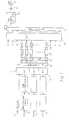
- Figure 1shows a COFDM coder 10 having inputs 12, 12a, 12b for receiving, in this example, three digital audio signals or transmission.
- the signal applied to input 12is passed through a convolutional coder 14 and thence to a time interleaving circuit 16, and the signals at inputs 12a and 12b are similarly treated in corresponding circuits.
- the outputs of the time interleaving circuitsare then assembled in a matrix 18.
- the matrix 18also receives header and/or synchronising information from an input 20.
- the matrix 18When the matrix 18 contains a complete frame of data, it is then extracted serially and turned into parallel format, illustratively by means of a shift register 22.
- the output of the matrix 18is clocked in from one end of the shift register, and when the shift register is full the outputs from its individual stages are applied to a frequency interleaving circuit 24.
- the signalsFrom the frequency interleaving circuit 24 the signals are applied to differential coding circuits 26 which apply known differential coding techniques.
- the outputs of the differential coding circuits 26are applied to a series of quadrature phase shift keying (QPSK) modulators 28.
- QPSKquadrature phase shift keying
- QPSKquadrature phase shift keying
- the number of bits required to fill the shift registermay in one example be defined as 3072 bits, and this number of bits is termed a 'symbol'.
- 1536 circuits 28which modulate the 3072 bits onto 1536 closely spaced carriers. These carriers are then applied to a fast Fourier transform (FFT) circuit 30.
- the FFT circuit 30has 2048 inputs and 2048 outputs.
- the phase modulator circuits 28are thus connected to the middle 1536 inputs, and the first 256 inputs and the last 256 inputs receive zero value inputs. This ensures that the top end of the baseband spectrum does not interfere with the bottom end of the first harmonic, introduced by the transform process.
- the FFT circuit 30is, strictly speaking, an inverse FFT circuit and is designated FFT -1 , and transforms the inputs which represent 1536 carriers at closely spaced frequencies into an output in the time domain. This output is reconverted back from parallel into serial form, illustratively by a shift register 32.
- the FFT circuit 30operates symbol-by-symbol.
- the time between the start of operation for one symbol and the nextis the symbol period T s .
- the symbol period T s and the carrier frequencies at which the modulators 28 operateare related, in that the closely-spaced carrier frequencies are spaced by a multiple of 1/T s . This gives the multiplex the property of orthogonality.
- the output of the shift register 32is then applied to a circuit 34 which adds a guard interval to each symbol as received from the shift register.
- a circuit 34which adds a guard interval to each symbol as received from the shift register.
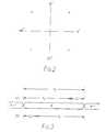
- FIG 3shows three successive symbol periods T s for symbols N-1, N and N+1.
- the circuit 34operates so that there is effectively a guard band between successive symbols. This is in fact achieved as shown at (a) in Figure 3.
- the datais compressed so as to be transmitted in a portion t s of the total symbol period T s , and the remaining portion indicated by the Greek letter delta ( ⁇ ) is filled by repeating the first part of the data in the active symbol period t s . This means that any time duration equal to t s within the overall symbol period T s will contain all the data bits.
- the output of the guard interval circuit 34is applied to a digital-to-analogue converter 36 and then to an output 38 for transmission over a broadcast transmission link.
- the datacan be processed ad the receiver so long as all the data in the active signal period t s is received, regardless of exactly where the period t s falls in the overall symbol period T s .
- a receivercan still decode the data if the signal shown in Figure 3 has added to it another version of the same signal, delayed by an arbitrary amount, so long as that delay is less than the duration delta, namely the length of the guard interval.
- the decodingwill be correct provided that the receiver does not mix the data relating to two successive symbols.
- the receiveris arranged to select the last portion of length t s in each symbol period T s , as shown at (b) in Figure 3. Signals delayed up to an amount equal to delta will correctly combine with the main signal without affecting the demultiplexed output at the receiver.
- the systemcan furthermore cope with the simultaneous reception of signals from two different transmitters, at different distances from the receiver, which are transmitting the same programme on the same frequency. This then enables the construction of the so-called Single Frequency Network (SFN).
- SFNSingle Frequency Network
- the systemcan also be shown to have a substantial degree of resistance to Doppler effects, such as occur in mobile receivers, see the references quoted in the introduction above.
- the results describedare achieved by the discrete Fourier transform as follows.
- the different data bits making up the symbolare carried (actually in pairs) on different carriers, which maintain their values for a symbol period.
- the datais thus represented in the frequency domain.
- the effect of the Fourier transformis to construct the equivalent waveform in the time domain.
- the Fourier transformfurthermore permits easy implementation of time and frequency interleaving to distribute the data over the channel in such a way that when combined with the error protection provided by the coding scheme errors can be corrected to a substantial degree. This means that the signal has acquired a substantial degree of immunity to frequency selective fading.
- a corresponding receiver 110is shown in Figure 4. This is shown conceptually as a mirror image of the transmitter illustrated in Figure 1, and corresponding elements have reference numerals differing by 100.
- a practical receiversince only one programme will normally be received, it will be possible to time de-interleave the programmes first and select for processing only the programme desired at that time. This reduces the processing load.
- the transmitted signalis received at an input 138 and is applied to an analogue-to-digital converter 136.
- the active symbol period t sis then selected by circuit 134 in the manner described above with reference to Figure 3, namely the last t s of the overall symbol period T s is taken.
- the signalis then applied to a shift register 132 which converts it to parallel format for application to the FFT circuit 130, which transforms the signal from the time domain back into the frequency, domain on a symbol-by-symbol basis.
- the signals which were at the inputs to FFT 30 in the transmitterare now re-created.
- the frequency domain outputs of FFT circuit 130are phase demodulated by demodulators 128. It will be appreciated that only the middle 1536 of the 2048 outputs need to be demodulated.
- the demodulated signalsare differentially decoded by circuits 126, and frequency de-interleaved at 124.
- a shift register 122reconverts the signals to serial form, and the data is then re-formatted in a matrix 118, from which the constituent data streams can be read out.
- Each audio signalis time de-interleaved in a circuit 116 and convolutionally decoded in a decoder 114 for application to an output 112.
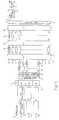
- a COFDM transmitter 40 embodying the inventionis shown in block diagram form in Figure 5. Much of this is identical to Figure 1 and carries the same reference numerals, and will not be described again.
- the outputs of the FFT circuit 30are applied to limiters 42 which provide a simple amplitude limiting function, though a more complex limiting function could be contemplated.
- the thus-limited signalsare then applied to a (forward) FFT circuit 44 which reverses the operation of the inverse FFT circuit 30 and converts the signals back to the frequency domain.
- the FFT circuit 44is like the FFT circuit 130 in the receiver. Were the limiters 42 not present, the outputs of FFT 44 would in theory be identical to the inputs of FFT 30. Because of the limiters 42 they are non identifical, and various changes will have been introduced. Selected ones of these changes are then removed or reduced by appropriate adjustment achieved in individual correction circuits 46.
- the adjusted signalsare then re-transformed by a second inverse FFT circuit 48, and it is the output of this circuit which is applied to shift register 32 for transmission.
- Figure 6represents, in the frequency domain, the set of 1536 carriers.
- the carriersare all of equal amplitude, and thus between the origin and carrier 1536 there is unity amplitude, and outside this region there is zero amplitude.
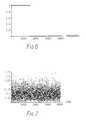
- the amplitudesare as shown in Figure 7. In the example illustrated, this gives rise to amplitude peaks of about 1.75 on the arbitrary scale used.
- This signalis clipped at unity in the circuits 42 to produce the time domain representation as shown in Figure 8, in which all values above 1.0 have now been reduced to 1.0, and all values below 1.0 are unchanged.
- Figure 9shows the phases of the carriers. There are four phases, represented on an arbitrary scale respectively at 0, + ⁇ /2, - ⁇ /2 and ⁇ on the Y-axis in the figure. The values + ⁇ and - ⁇ correspond to the coincident +180° and -180° phase positions. Because of the spectrum folding or aliasing effect, the values shown below 4096 are conceptually the same as those just below zero on the X-axis, and thus the right-hand part of the figure can conveniently be considered as wrapped around to the left hand edge; the plot is substantially symmetrical about carrier 768. As is seen in Figure 9, the phase values are not now precise but are spread around the nominal values. The harder the signals are limited, the greater is the spread.
- Figure 10shows that the amplitudes have now also varied. Over the in-band region of carriers up to 1536 this variation is desire. It is the use of this variation that gives the redundancy the system requires in order to allow it to reduce the peak-to-mean power ratio, as indicated above. However there are now substantial out-of-band amplitude components above carrier 1536 up to carrier 4096. These out-of-band intermodulation products are in general undesirable as they will cause interference with adjacent signals.
- correction circuitsthus perform two operations:
- Figure 14is a diagram similar to Figure 13 of the signal after three iterations.
- transform to be usedis the Fourier transform, and it is unlikely in practice to be any other form of transform.
- transforms or encoding functionswhich have the required properties, such as of reversibility and preserving orthogonality, could be employed.
- the methodcan be generalised to any modulation system which carries the information in the phases of the signal.
- the individual phasescould be adjusted to reduce the peaks in the overall signal.
- the inventionis of particular utility with and has been described in the context of the transmission of audio or video signals, but is not limited thereto and can be used more generally for data transmission.
- the terms +"transmission” and “transmitter”are not limited to broadcast transmission but are intended to cover signal sourcing of any type, including point-to-point transmission and also recording for example.
- the effect of not resetting the phases of the active carriersis identical to allowing the intermodulation products to remain in the signal.
- the main effectis a loss of noise margin.
- the peak-to-mean power ratiocan be reduced to around or below 6dB by applying the methods described.
- An amplifier operating with this amount of headroomshould not generate a significant amount of out-of-band components which would otherwise cause interference to adjacent DAB blocks.
- the amplitude of each carrierchanges slightly with each symbol in such a way that the overall peaks are effectively reduced.
- a B C D E6.0 8.5 7.7 8.2 7.3 5.0 8.2 7.0 7.8 6.5 4.0 7.8 6.2 7.3 5.6 3.0 7.4 5.4 6.7 4.7 2.0 6.9 4.6 6.1 4.0 1.0 6.2 3.8 5.4 3.4
Landscapes
- Engineering & Computer Science (AREA)
- Computer Networks & Wireless Communication (AREA)
- Signal Processing (AREA)
- Physics & Mathematics (AREA)
- Discrete Mathematics (AREA)
- General Physics & Mathematics (AREA)
- Mathematical Physics (AREA)
- Digital Transmission Methods That Use Modulated Carrier Waves (AREA)
- Reduction Or Emphasis Of Bandwidth Of Signals (AREA)
Abstract
Description
| A | B | C | D | E |
| 6.0 | 8.5 | 7.7 | 8.2 | 7.3 |
| 5.0 | 8.2 | 7.0 | 7.8 | 6.5 |
| 4.0 | 7.8 | 6.2 | 7.3 | 5.6 |
| 3.0 | 7.4 | 5.4 | 6.7 | 4.7 |
| 2.0 | 6.9 | 4.6 | 6.1 | 4.0 |
| 1.0 | 6.2 | 3.8 | 5.4 | 3.4 |
Claims (17)
- A method of transmitting a digital data stream on amany-carrier frequency-division-multiplex signal, comprising thesteps of:characterised in that the method further comprises:modulating a large number of closely-spaced carrierswith respective bits of the digital data by a modulation methodwhich carries the information in the phase or amplitude of theindividual carriers to provide a large number of first modulatedsignals;reversibly transforming the first modulated signalsfrom the frequency domain to the time domain to provide firsttime domain signals;limiting the first time domain signal to limit theiramplitude or power to provide limited time domain signals;inversely transforming the limited time domainsignals into a large number of second modulated signals in thefrequency domain;adjusting the phase and/or amplitude of some of thesecond modulated signals to provide a large number of adjustedsignals; andtransforming the adjusted signals from the frequencydomain to the time domain to provide second time domain signalsfor transmission.
- A many-carrier frequency-division-multiplextransmitter, comprising :characterised in that the transmitter further comprises:input means (12) for receiving a digital data stream fortransmission;means (26,28) coupled to the input means for modulating alarge number of closely-spaced carriers with respective bits ofthe digital data by a modulation method which carries theinformation in the phase or amplitude of the individual carriersto provide a large number of first modulated signals;first transform means (30) coupled to the modulating meansfor reversibly transforming the first modulated signals from thefrequency domain to the time domain to provide first time domainsignals;means (42) coupled to the first transform means forlimiting the first time domain signals to limit their amplitudeor power to provide limited time domain signals;second transform means (44) coupled to the limiting meansfor inversely transforming the limited time domain signals intoa large number of second modulated signals in the frequencydomain;means (46) coupled to the second transform means foradjusting the phase and/or amplitude of some of the secondmodulated signals to provide a large number of adjusted signals;andthird transform means (48) coupled to the adjusting meansfor transforming the adjusted signals from the frequency domainto the time domain to provide second time domain signals fortransmission.
- A transmitter according to claim 2, in which theadjusting means resets the phases of at least some of the secondmodulated signals.
- A transmitter according to claim 2, in which theadjusting means filters out some of the second modulatedsignals.
- A transmitter according to claim 2, in which thereare more first time domain signals than there are firstmodulated signals, and the adjusting means reduces the amplitudeof some of the second modulated signals which do not correspondto first modulated signals.
- A transmitter according to claim 2, in which themodulating means, first transform means, limiting means, secondtransform means, adjusting means, and third transform means,operate on successive groups of data bits.
- A transmitter according to claim 6, in which theperiodicity of the said successive groups in Ts, and the spacingof the carriers is 1/Ts or a multiple thereof.
- A transmitter according to claim 2, in which themodulating means is a quadrature phase shift keying or 4-PSKmodulator.
- A transmitter according to claim 2, in which thesecond transform means transforms with a Fourier transform, andthe first and third transform means transform with an inverseFourier transform.
- A transmitter according to claim 2, in which thelimiting means, second transform means, adjusting means, andthird transform means are repeated one or more times to providean iterative operation.
- A transmitter according to claim 2, in which themodulation means modulates in accordance with a phase shiftkeying modulation method.
- A method of transmitting a digital data stream on amany-carrier frequency-division-multiplex signal, comprising thesteps of:characterised in that the method further comprises:modulating a large number of closely-spaced carrierswith respective bits of the digital data to provide a largenumber of modulated signals;reversibly encoding the modulated signals by anencoding function to provide encoded signals;subjecting the encoded signals to a predeterminedfunction to provide modified encoded signals;decoding the modified encoded signals to providedecoded signals;adjusting at least some of the decoded signals toconform more closely with the modulated signals and provideadjusted signals; andrecoding the adjusted signals by the said encodingfunction to provide encoded output signals for transmission.
- Apparatus for transmitting a digital data stream on amany-carrier frequency-division-multiplex signal, comprising:characterised in that the apparatus further comprises:input means (12) for receiving a digital data stream fortransmission;means (26,28) coupled to the input means for modulating alarge number of closely-spaced carriers with respective bits ofthe digital data to provide a large number of modulated signals;encoding means (30) coupled to the modulating means forreversibly encoding the modulated signals by an encodingfunction to provide encoded signals;means (42) coupled to the encoding means for subjectingthe encoded signals to a predetermined function to providemodified encoded signals;decoding means (44) coupled to the function subjectingmeans for decoding the modified encoded signals to providedecoded signals;means (46) coupled to the decoding means for adjusting atleast some of the decoded signals to conform more closely withthe modulated signals and provide adjusted signals; andrecoding means (48) coupled to the adjusting means forrecoding the adjusted signals by the said encoding function toprovide encoded output signals for transmission.
- Apparatus according to claim 13, in which the meansfor subjecting the encoded signals to a predetermined functioncomprises means for limiting the encoded signals.
- Apparatus according to claim 13, in which thedecoding means comprises transform means for transforming themodified encoded signals from the time domain into a largenumber of decoded signals in the frequency domain.
- Apparatus according to claim 13, in which the meansfor adjusting at least some of the decoded signals comprisesmeans for adjusting the phase and/or amplitude of some of thedecoded signals.
- Apparatus according to claim 13, in which therecoding means comprises means for transforming the adjustedsignals from the frequency domain to the time domain.
Applications Claiming Priority (3)
| Application Number | Priority Date | Filing Date | Title |
|---|---|---|---|
| GB9218874 | 1992-09-07 | ||
| GB929218874AGB9218874D0 (en) | 1992-09-07 | 1992-09-07 | Improvements relating to the transmission of frequency division multiplex signals |
| PCT/GB1993/001884WO1994006231A1 (en) | 1992-09-07 | 1993-09-06 | Digital signal transmission system using frequency division multiplex |
Publications (2)
| Publication Number | Publication Date |
|---|---|
| EP0658295A1 EP0658295A1 (en) | 1995-06-21 |
| EP0658295B1true EP0658295B1 (en) | 1998-12-23 |
Family
ID=10721500
Family Applications (1)
| Application Number | Title | Priority Date | Filing Date |
|---|---|---|---|
| EP94908868AExpired - LifetimeEP0658295B1 (en) | 1992-09-07 | 1993-09-06 | Digital signal transmission system using frequency division multiplex |
Country Status (7)
| Country | Link |
|---|---|
| US (1) | US5610908A (en) |
| EP (1) | EP0658295B1 (en) |
| JP (1) | JPH08501195A (en) |
| AU (1) | AU4975493A (en) |
| DE (1) | DE69322785T2 (en) |
| GB (2) | GB9218874D0 (en) |
| WO (1) | WO1994006231A1 (en) |
Cited By (1)
| Publication number | Priority date | Publication date | Assignee | Title |
|---|---|---|---|---|
| DE102006011379A1 (en)* | 2006-03-09 | 2007-09-13 | Deutsches Zentrum für Luft- und Raumfahrt e.V. | Method for suppression of spectral sidelobes in transmission systems based on OFDM |
Families Citing this family (124)
| Publication number | Priority date | Publication date | Assignee | Title |
|---|---|---|---|---|
| US6075817A (en)* | 1991-12-23 | 2000-06-13 | Digital Compression Technology | Compressive communication and storage system |
| US7239666B1 (en) | 1994-09-09 | 2007-07-03 | Sony Corporation | Communication system |
| JP3577754B2 (en)* | 1994-09-09 | 2004-10-13 | ソニー株式会社 | Communication method and device |
| GB9418514D0 (en)* | 1994-09-14 | 1994-11-02 | At & T Global Inf Solution | Information transmission system |
| US5838732A (en)* | 1994-10-31 | 1998-11-17 | Airnet Communications Corp. | Reducing peak-to-average variance of a composite transmitted signal generated by a digital combiner via carrier phase offset |
| EP0743768B1 (en)* | 1994-12-05 | 2004-05-12 | Ntt Mobile Communications Network Inc. | Device and method for multiplexing signal |
| GB2296165B (en)* | 1994-12-15 | 1999-12-29 | Int Mobile Satellite Org | Multiplex communication |
| EP0719001A1 (en)* | 1994-12-22 | 1996-06-26 | ALCATEL BELL Naamloze Vennootschap | DMT modulator |
| US5835536A (en)* | 1995-02-02 | 1998-11-10 | Motorola, Inc. | Method and apparatus for reducing peak-to-average requirements in multi-tone communication circuits |
| WO1996027962A2 (en)* | 1995-03-03 | 1996-09-12 | Philips Electronics N.V. | Error protected multichannel digital data transmission system and method having graceful degration quality through multi-resolution, and transmitter station and receiver station for use in such system |
| EP0735731B1 (en)* | 1995-03-31 | 2004-05-12 | Victor Company Of Japan, Limited | Multicarrier modulator demodulator, with arrangements for reducing peak power |
| GB9523406D0 (en)* | 1995-11-16 | 1996-01-17 | Aromascan Plc | Sensor transduction |
| GB2309363B (en)* | 1996-01-17 | 2000-07-12 | Motorola Ltd | Multicarrier communication system and method for peak power control |
| SE504897C2 (en)* | 1996-02-14 | 1997-05-26 | Telia Ab | Procedure and apparatus in an OFDM system with variable duration of symbol burst |
| DE69630942D1 (en)* | 1996-02-16 | 2004-01-15 | St Microelectronics Srl | Automatic detection of the transmission mode in receivers of digital audio signals |
| SE515218C2 (en)* | 1996-02-19 | 2001-07-02 | Ericsson Telefon Ab L M | Device and method for cable TV networks |
| US5914933A (en)* | 1996-03-08 | 1999-06-22 | Lucent Technologies Inc. | Clustered OFDM communication system |
| FR2746562B1 (en)* | 1996-03-22 | 1998-06-05 | Thomson Csf | TRANSMITTER OF DIGITAL RADIOPHONY SIGNALS |
| US6002722A (en)* | 1996-05-09 | 1999-12-14 | Texas Instruments Incorporated | Multimode digital modem |
| US6757913B2 (en) | 1996-07-15 | 2004-06-29 | Gregory D. Knox | Wireless music and data transceiver system |
| US6771590B1 (en) | 1996-08-22 | 2004-08-03 | Tellabs Operations, Inc. | Communication system clock synchronization techniques |
| US6118758A (en)* | 1996-08-22 | 2000-09-12 | Tellabs Operations, Inc. | Multi-point OFDM/DMT digital communications system including remote service unit with improved transmitter architecture |
| US6122246A (en)* | 1996-08-22 | 2000-09-19 | Tellabs Operations, Inc. | Apparatus and method for clock synchronization in a multi-point OFDM/DMT digital communications system |
| US5790514A (en)* | 1996-08-22 | 1998-08-04 | Tellabs Operations, Inc. | Multi-point OFDM/DMT digital communications system including remote service unit with improved receiver architecture |
| US6950388B2 (en)* | 1996-08-22 | 2005-09-27 | Tellabs Operations, Inc. | Apparatus and method for symbol alignment in a multi-point OFDM/DMT digital communications system |
| JP3407558B2 (en)* | 1996-08-23 | 2003-05-19 | ソニー株式会社 | Transmission method, transmission device, reception method, reception device, multiple access method, and multiple access system |
| WO1998009385A2 (en)* | 1996-08-29 | 1998-03-05 | Cisco Technology, Inc. | Spatio-temporal processing for communication |
| US5825826A (en)* | 1996-09-30 | 1998-10-20 | Motorola, Inc. | Method and apparatus for frequency domain ripple compensation for a communications transmitter |
| US6072769A (en)* | 1997-03-04 | 2000-06-06 | At&T Corporation | Method for multitone division multiple access communications |
| GB9709063D0 (en)* | 1997-05-02 | 1997-06-25 | British Broadcasting Corp | Improvements to OFDM symbol synchronization |
| JP3239084B2 (en)* | 1997-05-30 | 2001-12-17 | 株式会社次世代デジタルテレビジョン放送システム研究所 | Multicarrier transmission interleaving apparatus and method |
| KR19990003242A (en) | 1997-06-25 | 1999-01-15 | 윤종용 | Structural Punched Convolutional Codes and Decoders |
| US6175551B1 (en) | 1997-07-31 | 2001-01-16 | Lucent Technologies, Inc. | Transmission system and method employing peak cancellation to reduce the peak-to-average power ratio |
| US6026123A (en)* | 1997-08-02 | 2000-02-15 | Williams; Thomas H. | Digital transmission system with high immunity to dynamic linear distortion |
| WO1999012294A1 (en)* | 1997-08-28 | 1999-03-11 | Kabushiki Kaisha Toshiba | Multi-carrier transmitter |
| USRE43703E1 (en) | 1997-09-04 | 2012-10-02 | Sony Deutschland Gmbh | Transmission system for OFDM-signals with optimized synchronization |
| US6301221B1 (en)* | 1997-09-10 | 2001-10-09 | Hewlett-Packard Company | Methods and apparatus for encoding data |
| WO1999023820A1 (en) | 1997-11-03 | 1999-05-14 | International Communications Products, Inc. | Link adapter interface for upgrading existing satellite communication system for enhanced modulation and coding |
| FR2771242B1 (en)* | 1997-11-14 | 2003-10-24 | Itis | METHOD AND DEVICE FOR REDUCING THE PEAK FACTOR OF DIGITAL BROADCASTING OR TELEVISION BROADCASTING SIGNALS |
| US6130918A (en)* | 1997-12-01 | 2000-10-10 | Nortel Networks Limited | Method and apparatus for reducing the peak-to-average ratio in a multicarrier communication system |
| JPH11298436A (en)* | 1998-02-13 | 1999-10-29 | Sony Corp | Modulation method, modulating device, demodulation method and demodulating device |
| US6301268B1 (en)* | 1998-03-10 | 2001-10-09 | Lucent Technologies Inc. | Communication method for frequency division multiplexing signalling systems with reduced average power requirements |
| DE19811830C2 (en)* | 1998-03-18 | 2002-05-29 | Siemens Ag | Method for determining transmission errors in a serial data stream transmitted using a multi-carrier method |
| US6377566B1 (en) | 1998-03-30 | 2002-04-23 | Agere Systems Guardian Corp. | OFDM subcarrier hopping in a multi service OFDM system |
| DK1068704T3 (en) | 1998-04-03 | 2012-09-17 | Tellabs Operations Inc | Impulse response shortening filter, with additional spectral constraints, for multi-wave transfer |
| US6631175B2 (en)* | 1998-04-03 | 2003-10-07 | Tellabs Operations, Inc. | Spectrally constrained impulse shortening filter for a discrete multi-tone receiver |
| US7440498B2 (en)* | 2002-12-17 | 2008-10-21 | Tellabs Operations, Inc. | Time domain equalization for discrete multi-tone systems |
| US6240141B1 (en) | 1998-05-09 | 2001-05-29 | Centillium Communications, Inc. | Lower-complexity peak-to-average reduction using intermediate-result subset sign-inversion for DSL |
| DE19824233B4 (en)* | 1998-05-29 | 2005-10-06 | Telefonaktiebolaget Lm Ericsson (Publ) | amplitude limiting |
| US6795424B1 (en)* | 1998-06-30 | 2004-09-21 | Tellabs Operations, Inc. | Method and apparatus for interference suppression in orthogonal frequency division multiplexed (OFDM) wireless communication systems |
| KR100369996B1 (en)* | 1998-07-31 | 2003-04-23 | 엘지전자 주식회사 | Digital TV transmission system and reception system |
| GB9816820D0 (en) | 1998-08-04 | 1998-09-30 | Koninkl Philips Electronics Nv | Orthogonal signal transmitter |
| US6442221B1 (en)* | 1998-09-22 | 2002-08-27 | Zenith Electronics Corporation | Ghost eliminating equalizer |
| FR2785113B1 (en)* | 1998-10-22 | 2001-02-02 | Canon Kk | METHOD AND DEVICE FOR REDUCING THE PEAK-TO-AVERAGE RATIO OF AN ORTHOGONAL FREQUENCY DIVISION MULTIPLEXING TRANSMISSION |
| FR2785114B1 (en)* | 1998-10-22 | 2001-02-02 | Canon Kk | METHOD AND DEVICE FOR REDUCING THE PEAK-TO-AVERAGE RATIO OF AN ORTHOGONAL FREQUENCY DIVISION MULTIPLEXING TRANSMISSION |
| GB9823145D0 (en) | 1998-10-23 | 1998-12-16 | Philips Electronics Nv | Radio communication system |
| AT408395B (en)* | 1998-12-21 | 2001-11-26 | Ericsson Austria Ag | METHOD FOR SUPPRESSING NARROW FREQUENCY BANDS |
| AT408396B (en)* | 1998-12-21 | 2001-11-26 | Ericsson Austria Ag | METHOD FOR TRANSMITTING DATA |
| US6111919A (en)* | 1999-01-20 | 2000-08-29 | Intellon Corporation | Synchronization of OFDM signals |
| FR2788907B1 (en)* | 1999-01-27 | 2001-04-13 | St Microelectronics Sa | GUARD INTERVAL GENERATION IN A DMT MODULATION TRANSMISSION |
| AU2692300A (en)* | 1999-02-25 | 2000-09-14 | Nippon Hoso Kyokai | Digital broadcasting apparatus |
| US6269132B1 (en) | 1999-04-26 | 2001-07-31 | Intellon Corporation | Windowing function for maintaining orthogonality of channels in the reception of OFDM symbols |
| US6074086A (en)* | 1999-04-26 | 2000-06-13 | Intellon Corporation | Synchronization of OFDM signals with improved windowing |
| US6952394B1 (en) | 1999-05-25 | 2005-10-04 | Samsung Electronics Co., Ltd. | Method for transmitting and receiving orthogonal frequency division multiplexing signal and apparatus therefor |
| FR2794914B1 (en)* | 1999-06-08 | 2002-03-01 | Sagem | PARAMETRABLE SYSTEM WITH TIME AND FREQUENTIAL INTERLACEMENT FOR THE TRANSMISSION OF DIGITAL DATA BETWEEN FIXED OR MOBILE STATIONS |
| US6278685B1 (en) | 1999-08-19 | 2001-08-21 | Intellon Corporation | Robust transmission mode |
| US6128350A (en)* | 1999-08-24 | 2000-10-03 | Usa Digital Radio, Inc. | Method and apparatus for reducing peak to average power ratio in digital broadcasting systems |
| US6985537B1 (en)* | 1999-09-15 | 2006-01-10 | Lucent Technologies Inc. | Symbol self synchronous interleaving method and apparatus for OFDM-based communication system |
| US6879640B1 (en)* | 1999-10-20 | 2005-04-12 | Broadcom Corporation | Method, apparatus and system for high-speed transmission on fiber optic channel |
| US6807145B1 (en) | 1999-12-06 | 2004-10-19 | Lucent Technologies Inc. | Diversity in orthogonal frequency division multiplexing systems |
| US6397368B1 (en) | 1999-12-06 | 2002-05-28 | Intellon Corporation | Forward error correction with channel adaptation |
| US6529868B1 (en)* | 2000-03-28 | 2003-03-04 | Tellabs Operations, Inc. | Communication system noise cancellation power signal calculation techniques |
| US6788349B2 (en)* | 2000-04-12 | 2004-09-07 | Her Majesty Of Queen In Right Of Canada, As Respresented By The Minister Of Industry | Method and system for broadcasting a digital data signal within an analog TV signal using Orthogonal Frequency Division Multiplexing |
| US6289000B1 (en) | 2000-05-19 | 2001-09-11 | Intellon Corporation | Frame control encoder/decoder for robust OFDM frame transmissions |
| US7298691B1 (en) | 2000-08-04 | 2007-11-20 | Intellon Corporation | Method and protocol to adapt each unique connection in a multi-node network to a maximum data rate |
| US7352770B1 (en)* | 2000-08-04 | 2008-04-01 | Intellon Corporation | Media access control protocol with priority and contention-free intervals |
| US7469297B1 (en) | 2000-08-04 | 2008-12-23 | Intellon Corporation | Mechanism for using a quasi-addressed response to bind to a message requesting the response |
| US6909723B1 (en) | 2000-08-04 | 2005-06-21 | Intellon Corporation | Segment bursting with priority pre-emption and reduced latency |
| US6907044B1 (en) | 2000-08-04 | 2005-06-14 | Intellon Corporation | Method and protocol to support contention-free intervals and QoS in a CSMA network |
| US6987770B1 (en) | 2000-08-04 | 2006-01-17 | Intellon Corporation | Frame forwarding in an adaptive network |
| US7295509B2 (en) | 2000-09-13 | 2007-11-13 | Qualcomm, Incorporated | Signaling method in an OFDM multiple access system |
| US6934676B2 (en)* | 2001-05-11 | 2005-08-23 | Nokia Mobile Phones Ltd. | Method and system for inter-channel signal redundancy removal in perceptual audio coding |
| DE10127346C2 (en)* | 2001-06-06 | 2003-07-17 | Siemens Ag | Multi-carrier data transmission system and method for suppressing interference in a multi-carrier data transmission system |
| US7020218B2 (en)* | 2001-06-18 | 2006-03-28 | Arnesen David M | Sliding-window transform with integrated windowing |
| JP3396815B2 (en)* | 2001-06-20 | 2003-04-14 | 富士通株式会社 | Data transmission method and data transmission device |
| FR2830391A1 (en)* | 2001-10-03 | 2003-04-04 | Canon Kk | Optimized HiperLan2 frame reception system detects burst end in Fresnel plane |
| US7002899B2 (en)* | 2001-10-09 | 2006-02-21 | Ati Technologies Inc. | Method and apparatus to improve SCDMA headroom |
| FR2832275B1 (en)* | 2001-11-12 | 2004-11-19 | Evolium Sas | PROCESS FOR CLIPPING SIGNALS WITH MULTIPLE CARRIERS TRANSMITTED BY A SAME NON-LINEAR AMPLIFIER |
| US7826466B2 (en)* | 2002-06-26 | 2010-11-02 | Atheros Communications, Inc. | Communication buffer scheme optimized for VoIP, QoS and data networking over a power line |
| US7120847B2 (en)* | 2002-06-26 | 2006-10-10 | Intellon Corporation | Powerline network flood control restriction |
| US8149703B2 (en)* | 2002-06-26 | 2012-04-03 | Qualcomm Atheros, Inc. | Powerline network bridging congestion control |
| WO2004038980A2 (en) | 2002-10-21 | 2004-05-06 | Intellon Corporation | Contention-free access intervals on a csma network |
| DE10317119A1 (en)* | 2003-04-14 | 2004-11-18 | Siemens Ag | Method, radio transceiver, mobile terminal and base station for data transmission in a multi-carrier system |
| FR2854514B1 (en)* | 2003-04-30 | 2006-12-15 | Spidcom Technologies | METHOD FOR TRANSMITTING DATA AND MODEM BY POWER CURRENT |
| DE10325839B4 (en)* | 2003-06-06 | 2012-03-08 | Lantiq Deutschland Gmbh | Method and circuit for crest factor reduction |
| US7440510B2 (en)* | 2003-09-15 | 2008-10-21 | Intel Corporation | Multicarrier transmitter, multicarrier receiver, and methods for communicating multiple spatial signal streams |
| US7366243B1 (en)* | 2003-10-29 | 2008-04-29 | Itt Manufacturing Enterprises, Inc. | Methods and apparatus for transmitting non-contiguous spread spectrum signals for communications and navigation |
| US7281187B2 (en) | 2003-11-20 | 2007-10-09 | Intellon Corporation | Using error checking bits to communicated an address or other bits |
| US8090857B2 (en)* | 2003-11-24 | 2012-01-03 | Qualcomm Atheros, Inc. | Medium access control layer that encapsulates data from a plurality of received data units into a plurality of independently transmittable blocks |
| DE602004020860D1 (en)* | 2003-12-25 | 2009-06-10 | Ntt Docomo Inc | Radio communication system, transmitter, receiver and radio communication method |
| US7649833B2 (en) | 2003-12-29 | 2010-01-19 | Intel Corporation | Multichannel orthogonal frequency division multiplexed receivers with antenna selection and maximum-ratio combining and associated methods |
| US20050152330A1 (en)* | 2004-01-12 | 2005-07-14 | Stephens Adrian P. | Clock recovery methods and apparatus |
| US7542517B2 (en) | 2004-02-02 | 2009-06-02 | Ibiquity Digital Corporation | Peak-to-average power reduction for FM OFDM transmission |
| US7660327B2 (en)* | 2004-02-03 | 2010-02-09 | Atheros Communications, Inc. | Temporary priority promotion for network communications in which access to a shared medium depends on a priority level |
| US7715425B2 (en)* | 2004-02-26 | 2010-05-11 | Atheros Communications, Inc. | Channel adaptation synchronized to periodically varying channel |
| US7835454B2 (en)* | 2004-04-30 | 2010-11-16 | Analog Devices, B.V. | Multicarrier modulation systems |
| JP4429795B2 (en) | 2004-05-06 | 2010-03-10 | 株式会社エヌ・ティ・ティ・ドコモ | Wireless communication system, wireless transmitter and wireless receiver |
| US7746758B2 (en)* | 2004-08-17 | 2010-06-29 | Nokia Corporation | Orthogonal-Frequency-Division-Multiplex-Packet-Aggregation (OFDM-PA) for wireless network systems using error-correcting codes |
| US7636370B2 (en)* | 2005-03-03 | 2009-12-22 | Intellon Corporation | Reserving time periods for communication on power line networks |
| US8670493B2 (en) | 2005-06-22 | 2014-03-11 | Eices Research, Inc. | Systems and/or methods of increased privacy wireless communications |
| US7822059B2 (en) | 2005-07-27 | 2010-10-26 | Atheros Communications, Inc. | Managing contention-free time allocations in a network |
| US8175190B2 (en) | 2005-07-27 | 2012-05-08 | Qualcomm Atheros, Inc. | Managing spectra of modulated signals in a communication network |
| US7944991B2 (en)* | 2005-10-27 | 2011-05-17 | Georgia Tech Research Corporation | Constrained clipping for peak-to-average power ratio (crest factor) reduction in multicarrier transmission systems |
| KR101223783B1 (en)* | 2006-03-06 | 2013-01-17 | 삼성전자주식회사 | Method and apparatus for symbol timing estimate in a wireless communication system |
| US8300798B1 (en) | 2006-04-03 | 2012-10-30 | Wai Wu | Intelligent communication routing system and method |
| EP2159966A1 (en) | 2007-05-10 | 2010-03-03 | Intellon Corporation | Managing distributed access to a shared medium |
| JP2009100190A (en)* | 2007-10-16 | 2009-05-07 | Nec Corp | Multi-carrier transmitter and its peak suppression method |
| GB2471876B (en)* | 2009-07-15 | 2011-08-31 | Toshiba Res Europ Ltd | Data communication method and apparatus |
| CN102939737B (en) | 2010-04-12 | 2015-10-21 | 高通股份有限公司 | For carrying out the forwarding of low overhead communication in a network |
| US9100102B2 (en) | 2011-01-11 | 2015-08-04 | Texas Instruments Incorporated | Method to use a preamble with band extension in power line communications |
| US9374646B2 (en)* | 2012-08-31 | 2016-06-21 | Starkey Laboratories, Inc. | Binaural enhancement of tone language for hearing assistance devices |
| US8891605B2 (en) | 2013-03-13 | 2014-11-18 | Qualcomm Incorporated | Variable line cycle adaptation for powerline communications |
| CA2887751C (en)* | 2015-04-10 | 2023-09-05 | Nautel Limited | Multiplex of high definition radio stations |
| CA3070530A1 (en) | 2020-01-30 | 2021-07-30 | Nautel Limited | Iboc compatible superposition modulation by independent modulators utilizing clipping noise from peak-to-average power reduction |
Family Cites Families (6)
| Publication number | Priority date | Publication date | Assignee | Title |
|---|---|---|---|---|
| US4495620A (en)* | 1982-08-05 | 1985-01-22 | At&T Bell Laboratories | Transmitting data on the phase of speech |
| US4679227A (en)* | 1985-05-20 | 1987-07-07 | Telebit Corporation | Ensemble modem structure for imperfect transmission media |
| US4881241A (en)* | 1988-02-24 | 1989-11-14 | Centre National D'etudes Des Telecommunications | Method and installation for digital communication, particularly between and toward moving vehicles |
| FR2658017B1 (en)* | 1990-02-06 | 1992-06-05 | France Etat | METHOD FOR BROADCASTING DIGITAL DATA, ESPECIALLY FOR BROADBAND BROADCASTING TO MOBILES, WITH TIME-FREQUENCY INTERLACING AND ASSISTING THE ACQUISITION OF AUTOMATIC FREQUENCY CONTROL, AND CORRESPONDING RECEIVER. |
| FR2671923B1 (en)* | 1991-01-17 | 1993-04-16 | France Etat | DEVICE FOR CONSISTENT DEMODULATION OF DIGITAL DATA INTERLACED IN TIME AND IN FREQUENCY, WITH ESTIMATION OF THE FREQUENTIAL RESPONSE OF THE TRANSMISSION AND THRESHOLD CHANNEL, AND CORRESPONDING TRANSMITTER. |
| JP2904986B2 (en)* | 1992-01-31 | 1999-06-14 | 日本放送協会 | Orthogonal frequency division multiplex digital signal transmitter and receiver |
- 1992
- 1992-09-07GBGB929218874Apatent/GB9218874D0/enactivePending
- 1993
- 1993-09-06JPJP6507010Apatent/JPH08501195A/enactivePending
- 1993-09-06WOPCT/GB1993/001884patent/WO1994006231A1/enactiveIP Right Grant
- 1993-09-06DEDE69322785Tpatent/DE69322785T2/ennot_activeExpired - Lifetime
- 1993-09-06EPEP94908868Apatent/EP0658295B1/ennot_activeExpired - Lifetime
- 1993-09-06GBGB9318430Apatent/GB2270819B/ennot_activeExpired - Fee Related
- 1993-09-06AUAU49754/93Apatent/AU4975493A/ennot_activeAbandoned
- 1993-09-06USUS08/392,875patent/US5610908A/ennot_activeExpired - Lifetime
Cited By (2)
| Publication number | Priority date | Publication date | Assignee | Title |
|---|---|---|---|---|
| DE102006011379A1 (en)* | 2006-03-09 | 2007-09-13 | Deutsches Zentrum für Luft- und Raumfahrt e.V. | Method for suppression of spectral sidelobes in transmission systems based on OFDM |
| DE102006011379B4 (en)* | 2006-03-09 | 2012-06-28 | Deutsches Zentrum für Luft- und Raumfahrt e.V. | Method for suppression of spectral sidelobes in transmission systems based on OFDM |
Also Published As
| Publication number | Publication date |
|---|---|
| WO1994006231A1 (en) | 1994-03-17 |
| GB9218874D0 (en) | 1992-10-21 |
| JPH08501195A (en) | 1996-02-06 |
| AU4975493A (en) | 1994-03-29 |
| DE69322785T2 (en) | 1999-05-20 |
| DE69322785D1 (en) | 1999-02-04 |
| EP0658295A1 (en) | 1995-06-21 |
| GB2270819B (en) | 1996-07-31 |
| US5610908A (en) | 1997-03-11 |
| GB9318430D0 (en) | 1993-10-20 |
| GB2270819A (en) | 1994-03-23 |
Similar Documents
| Publication | Publication Date | Title |
|---|---|---|
| EP0658295B1 (en) | Digital signal transmission system using frequency division multiplex | |
| CN1914871B (en) | Peak-to-average power reduction for FM OFDM transmission | |
| CA2385125C (en) | Method and apparatus for reducing peak to average power ratio in digital broadcasting systems | |
| US6452977B1 (en) | Method and apparatus for AM compatible digital broadcasting | |
| CN1143463C (en) | AM and digital coexisting broadcasting method and device | |
| EP0797878B1 (en) | Ofdm with variable subcarrier allocation | |
| US7342974B2 (en) | Channel estimation in OFDM systems | |
| US7319723B2 (en) | Apparatus and method for reducing PAPR in an OFDM mobile communication system | |
| CN1151643C (en) | Method and apparatus for demodulating and equalizing am compatible digital | |
| JPH11512242A (en) | Method of transmitting digital data via a radio broadcast channel having a fault and a receiver for digital data transmitted via a radio channel having a fault | |
| US7983358B2 (en) | Composite crest factor reduction | |
| RU2298877C2 (en) | Method and device for pulse overlap compensation in digital-modulation signals | |
| WO1995002289A1 (en) | Multiresolution ofdm | |
| Fernando et al. | Performance of turbo and trellis coded OFDM for LEO satellite channels in global mobile communications | |
| RU2645155C1 (en) | Method of transmission of informational narrow-band digital multimedia broadcasting | |
| Nystrom et al. | A flexible COFDM modem for the HD-Divine digital terrestrial broadcasting system | |
| Dittmer | Advances in digitally modulated RF systems | |
| JP2002171239A (en) | Modulating device | |
| Pandit et al. | Partial SLM using Wavelet Transform for BER Reduction in OFDM | |
| JPH1032558A (en) | Ofdm modulation and demodulation circuit | |
| Kaur et al. | THE COFDM MODULATION SYSTEM: THE HEART OF | |
| HK1103938B (en) | Peak-to-average power reduction for fm ofdm transmission |
Legal Events
| Date | Code | Title | Description |
|---|---|---|---|
| PUAI | Public reference made under article 153(3) epc to a published international application that has entered the european phase | Free format text:ORIGINAL CODE: 0009012 | |
| 17P | Request for examination filed | Effective date:19950320 | |
| AK | Designated contracting states | Kind code of ref document:A1 Designated state(s):BE DE FR IT | |
| 17Q | First examination report despatched | Effective date:19960528 | |
| GRAG | Despatch of communication of intention to grant | Free format text:ORIGINAL CODE: EPIDOS AGRA | |
| GRAG | Despatch of communication of intention to grant | Free format text:ORIGINAL CODE: EPIDOS AGRA | |
| GRAH | Despatch of communication of intention to grant a patent | Free format text:ORIGINAL CODE: EPIDOS IGRA | |
| GRAH | Despatch of communication of intention to grant a patent | Free format text:ORIGINAL CODE: EPIDOS IGRA | |
| GRAH | Despatch of communication of intention to grant a patent | Free format text:ORIGINAL CODE: EPIDOS IGRA | |
| GRAA | (expected) grant | Free format text:ORIGINAL CODE: 0009210 | |
| AK | Designated contracting states | Kind code of ref document:B1 Designated state(s):BE DE FR IT | |
| REF | Corresponds to: | Ref document number:69322785 Country of ref document:DE Date of ref document:19990204 | |
| ET | Fr: translation filed | ||
| PLBE | No opposition filed within time limit | Free format text:ORIGINAL CODE: 0009261 | |
| STAA | Information on the status of an ep patent application or granted ep patent | Free format text:STATUS: NO OPPOSITION FILED WITHIN TIME LIMIT | |
| 26N | No opposition filed | ||
| PGFP | Annual fee paid to national office [announced via postgrant information from national office to epo] | Ref country code:DE Payment date:20090922 Year of fee payment:17 | |
| PGFP | Annual fee paid to national office [announced via postgrant information from national office to epo] | Ref country code:BE Payment date:20090909 Year of fee payment:17 | |
| PGFP | Annual fee paid to national office [announced via postgrant information from national office to epo] | Ref country code:IT Payment date:20090911 Year of fee payment:17 | |
| BERE | Be: lapsed | Owner name:BRITISH *BROADCASTING CORP. Effective date:20100930 | |
| PG25 | Lapsed in a contracting state [announced via postgrant information from national office to epo] | Ref country code:IT Free format text:LAPSE BECAUSE OF NON-PAYMENT OF DUE FEES Effective date:20100906 | |
| REG | Reference to a national code | Ref country code:FR Ref legal event code:ST Effective date:20110531 | |
| REG | Reference to a national code | Ref country code:DE Ref legal event code:R119 Ref document number:69322785 Country of ref document:DE Effective date:20110401 | |
| PG25 | Lapsed in a contracting state [announced via postgrant information from national office to epo] | Ref country code:BE Free format text:LAPSE BECAUSE OF NON-PAYMENT OF DUE FEES Effective date:20100930 Ref country code:DE Free format text:LAPSE BECAUSE OF NON-PAYMENT OF DUE FEES Effective date:20110401 Ref country code:FR Free format text:LAPSE BECAUSE OF NON-PAYMENT OF DUE FEES Effective date:20100930 | |
| PGFP | Annual fee paid to national office [announced via postgrant information from national office to epo] | Ref country code:FR Payment date:20090908 Year of fee payment:17 |