EP0654352B1 - Mixed resolution printing for colour and monochrome printers - Google Patents
Mixed resolution printing for colour and monochrome printersDownload PDFInfo
- Publication number
- EP0654352B1 EP0654352B1EP94307806AEP94307806AEP0654352B1EP 0654352 B1EP0654352 B1EP 0654352B1EP 94307806 AEP94307806 AEP 94307806AEP 94307806 AEP94307806 AEP 94307806AEP 0654352 B1EP0654352 B1EP 0654352B1
- Authority
- EP
- European Patent Office
- Prior art keywords
- printhead
- resolution
- carriage
- printer according
- Prior art date
- Legal status (The legal status is an assumption and is not a legal conclusion. Google has not performed a legal analysis and makes no representation as to the accuracy of the status listed.)
- Expired - Lifetime
Links
Images


Classifications
- B—PERFORMING OPERATIONS; TRANSPORTING
- B41—PRINTING; LINING MACHINES; TYPEWRITERS; STAMPS
- B41J—TYPEWRITERS; SELECTIVE PRINTING MECHANISMS, i.e. MECHANISMS PRINTING OTHERWISE THAN FROM A FORME; CORRECTION OF TYPOGRAPHICAL ERRORS
- B41J2/00—Typewriters or selective printing mechanisms characterised by the printing or marking process for which they are designed
- B41J2/005—Typewriters or selective printing mechanisms characterised by the printing or marking process for which they are designed characterised by bringing liquid or particles selectively into contact with a printing material
- B41J2/01—Ink jet
- B41J2/17—Ink jet characterised by ink handling
- B41J2/175—Ink supply systems ; Circuit parts therefor
- B41J2/17503—Ink cartridges
- B41J2/17526—Electrical contacts to the cartridge
- B—PERFORMING OPERATIONS; TRANSPORTING
- B41—PRINTING; LINING MACHINES; TYPEWRITERS; STAMPS
- B41J—TYPEWRITERS; SELECTIVE PRINTING MECHANISMS, i.e. MECHANISMS PRINTING OTHERWISE THAN FROM A FORME; CORRECTION OF TYPOGRAPHICAL ERRORS
- B41J2/00—Typewriters or selective printing mechanisms characterised by the printing or marking process for which they are designed
- B41J2/005—Typewriters or selective printing mechanisms characterised by the printing or marking process for which they are designed characterised by bringing liquid or particles selectively into contact with a printing material
- B41J2/01—Ink jet
- B41J2/135—Nozzles
- B41J2/145—Arrangement thereof
- B41J2/15—Arrangement thereof for serial printing
- B—PERFORMING OPERATIONS; TRANSPORTING
- B41—PRINTING; LINING MACHINES; TYPEWRITERS; STAMPS
- B41J—TYPEWRITERS; SELECTIVE PRINTING MECHANISMS, i.e. MECHANISMS PRINTING OTHERWISE THAN FROM A FORME; CORRECTION OF TYPOGRAPHICAL ERRORS
- B41J2/00—Typewriters or selective printing mechanisms characterised by the printing or marking process for which they are designed
- B41J2/005—Typewriters or selective printing mechanisms characterised by the printing or marking process for which they are designed characterised by bringing liquid or particles selectively into contact with a printing material
- B41J2/01—Ink jet
- B41J2/17—Ink jet characterised by ink handling
- B41J2/175—Ink supply systems ; Circuit parts therefor
- B41J2/17503—Ink cartridges
- B41J2/1752—Mounting within the printer
- B—PERFORMING OPERATIONS; TRANSPORTING
- B41—PRINTING; LINING MACHINES; TYPEWRITERS; STAMPS
- B41J—TYPEWRITERS; SELECTIVE PRINTING MECHANISMS, i.e. MECHANISMS PRINTING OTHERWISE THAN FROM A FORME; CORRECTION OF TYPOGRAPHICAL ERRORS
- B41J2/00—Typewriters or selective printing mechanisms characterised by the printing or marking process for which they are designed
- B41J2/005—Typewriters or selective printing mechanisms characterised by the printing or marking process for which they are designed characterised by bringing liquid or particles selectively into contact with a printing material
- B41J2/01—Ink jet
- B41J2/21—Ink jet for multi-colour printing
- B41J2/2121—Ink jet for multi-colour printing characterised by dot size, e.g. combinations of printed dots of different diameter
- B41J2/2125—Ink jet for multi-colour printing characterised by dot size, e.g. combinations of printed dots of different diameter by means of nozzle diameter selection
- B—PERFORMING OPERATIONS; TRANSPORTING
- B41—PRINTING; LINING MACHINES; TYPEWRITERS; STAMPS
- B41J—TYPEWRITERS; SELECTIVE PRINTING MECHANISMS, i.e. MECHANISMS PRINTING OTHERWISE THAN FROM A FORME; CORRECTION OF TYPOGRAPHICAL ERRORS
- B41J2/00—Typewriters or selective printing mechanisms characterised by the printing or marking process for which they are designed
- B41J2/005—Typewriters or selective printing mechanisms characterised by the printing or marking process for which they are designed characterised by bringing liquid or particles selectively into contact with a printing material
- B41J2/01—Ink jet
- B41J2/21—Ink jet for multi-colour printing
- B41J2/2132—Print quality control characterised by dot disposition, e.g. for reducing white stripes or banding
- B—PERFORMING OPERATIONS; TRANSPORTING
- B41—PRINTING; LINING MACHINES; TYPEWRITERS; STAMPS
- B41J—TYPEWRITERS; SELECTIVE PRINTING MECHANISMS, i.e. MECHANISMS PRINTING OTHERWISE THAN FROM A FORME; CORRECTION OF TYPOGRAPHICAL ERRORS
- B41J2/00—Typewriters or selective printing mechanisms characterised by the printing or marking process for which they are designed
- B41J2/485—Typewriters or selective printing mechanisms characterised by the printing or marking process for which they are designed characterised by the process of building-up characters or image elements applicable to two or more kinds of printing or marking processes
- B41J2/505—Typewriters or selective printing mechanisms characterised by the printing or marking process for which they are designed characterised by the process of building-up characters or image elements applicable to two or more kinds of printing or marking processes from an assembly of identical printing elements
- B41J2/5056—Typewriters or selective printing mechanisms characterised by the printing or marking process for which they are designed characterised by the process of building-up characters or image elements applicable to two or more kinds of printing or marking processes from an assembly of identical printing elements using dot arrays providing selective dot disposition modes, e.g. different dot densities for high speed and high-quality printing, array line selections for multi-pass printing, or dot shifts for character inclination
- B—PERFORMING OPERATIONS; TRANSPORTING
- B41—PRINTING; LINING MACHINES; TYPEWRITERS; STAMPS
- B41J—TYPEWRITERS; SELECTIVE PRINTING MECHANISMS, i.e. MECHANISMS PRINTING OTHERWISE THAN FROM A FORME; CORRECTION OF TYPOGRAPHICAL ERRORS
- B41J2/00—Typewriters or selective printing mechanisms characterised by the printing or marking process for which they are designed
- B41J2/525—Arrangement for multi-colour printing, not covered by group B41J2/21, e.g. applicable to two or more kinds of printing or marking process
- B—PERFORMING OPERATIONS; TRANSPORTING
- B41—PRINTING; LINING MACHINES; TYPEWRITERS; STAMPS
- B41J—TYPEWRITERS; SELECTIVE PRINTING MECHANISMS, i.e. MECHANISMS PRINTING OTHERWISE THAN FROM A FORME; CORRECTION OF TYPOGRAPHICAL ERRORS
- B41J3/00—Typewriters or selective printing or marking mechanisms characterised by the purpose for which they are constructed
- B41J3/54—Typewriters or selective printing or marking mechanisms characterised by the purpose for which they are constructed with two or more sets of type or printing elements
- G—PHYSICS
- G06—COMPUTING OR CALCULATING; COUNTING
- G06K—GRAPHICAL DATA READING; PRESENTATION OF DATA; RECORD CARRIERS; HANDLING RECORD CARRIERS
- G06K15/00—Arrangements for producing a permanent visual presentation of the output data, e.g. computer output printers
- G06K15/02—Arrangements for producing a permanent visual presentation of the output data, e.g. computer output printers using printers
- G06K15/10—Arrangements for producing a permanent visual presentation of the output data, e.g. computer output printers using printers by matrix printers
- G06K15/102—Arrangements for producing a permanent visual presentation of the output data, e.g. computer output printers using printers by matrix printers using ink jet print heads
- G06K15/105—Multipass or interlaced printing
- G06K15/107—Mask selection
- B—PERFORMING OPERATIONS; TRANSPORTING
- B41—PRINTING; LINING MACHINES; TYPEWRITERS; STAMPS
- B41J—TYPEWRITERS; SELECTIVE PRINTING MECHANISMS, i.e. MECHANISMS PRINTING OTHERWISE THAN FROM A FORME; CORRECTION OF TYPOGRAPHICAL ERRORS
- B41J2/00—Typewriters or selective printing mechanisms characterised by the printing or marking process for which they are designed
- B41J2/005—Typewriters or selective printing mechanisms characterised by the printing or marking process for which they are designed characterised by bringing liquid or particles selectively into contact with a printing material
- B41J2/01—Ink jet
- B41J2/135—Nozzles
- B41J2/14—Structure thereof only for on-demand ink jet heads
- G—PHYSICS
- G06—COMPUTING OR CALCULATING; COUNTING
- G06K—GRAPHICAL DATA READING; PRESENTATION OF DATA; RECORD CARRIERS; HANDLING RECORD CARRIERS
- G06K2215/00—Arrangements for producing a permanent visual presentation of the output data
- G06K2215/0082—Architecture adapted for a particular function
- G06K2215/0094—Colour printing
Definitions
- This inventionrelates generally to printers, and more specifically to printing devices and techniques for monochrome and color printers capable of achieving high quality resolution.
- High quality printersare typically characterized by numbers indicating their resolution in dots per inch (dpi). This resolution is usually described in the context of a two dimension coordinate system where one number indicates the resolution in the x-axis (as used herein, x-axis means the carriage scan axis for a swath printer), and another number indicates the resolution in the y-axis (as used herein, y-axis means the media advance axis for a swath printer).
- a resolution of 300/300 dpigenerally indicates a carriage-scan axis resolution of 300 dots per inch and a media-advance axis resolution of 300 dots per inch.
- a printhead's resolutionis often identified by its nozzle pitch (i.e., the distance between adjacent nozzles on a printhead), and a print mode resolution is often identified by its pixel addressability (i.e., the distance between adjacent pixels in a printout).
- a 1/300th inch nozzle pitch printheadcould be used to create a 600 pixel/inch printout in the media-advance axis by changing the incremental advance distance of the media at the end of a swath and then employing a multi-pass print mode.
- a 1/300th inch nozzle pitch printheadcould be used to create a 600 pixel/inch printout in the carriage scan axis by increasing the firing frequency of the printhead and/or changing the carriage scan speed.
- JP-A-05 261 941describes an ink-jet recording head which prints black dots which are larger than colour dots, a black printhead having a lower resolution than the colour printhead.
- WO-A-91 089 02discloses a printhead where the vertical spacing of the black orifices is less than the vertical spacing of colour orifices.
- every other black orificeis used so that both black and colour are printed at the same vertical resolution.
- JP-A-61 104 856describes an ink-jet printer which permits simultaneous printing of colour images without reducing printing speed of black characters, in which the printhead is provided with more black ink nozzles than colour ink nozzles.
- WO-A-90 029 25describes a dual mode ink-jet printer for either high quality or high speed printing.
- the spacing between the nozzles in the colour ink arraysis greater than the spacing between the nozzles in the black ink array.
- a related objectis to decrease research and development costs as well as decrease the time for bringing higher resolution printers to market.
- a feature of the inventionis to provide a printer having higher base resolution for its black printing component and a lower base resolution for its color printing components such as cyan, magenta and yellow.
- a related objectis to integrate both of the aforesaid black and color printing components into the same printing mechanism in order to provide composite printing of higher resolution black and lower resolution color at the same time.
- Another important feature of the inventionis to provide increased throughput for the higher resolution monochrome component of the color printer.
- a wider swath monochrome printheadsuch as a high resolution black printhead which produces approximately 600 dpi sized printout dots is mounted on the same carriage as narrower swath color printheads such as lower resolution cyan, magenta and yellow printheads which produce approximately 300 dpi sized printout dots, with the wider swath black printhead having overlapping printing alignment with all of the narrower swath color printheads.
- the wider swath black printheadhas a 300 nozzle swath with a nozzle pitch of 1/600th inch to create a swath of approximately one-half inch, and the narrower swath color printheads each have a 100 nozzle swath with a nozzle pitch of 1/300th inch to create a swath of approximately one-third inch.
- the output quality of a printed pageis a function of printhead resolution. The higher the resolution the better the print quality. Also, in a swath printer employing a scanning carriage, the speed at which the output can be obtained is a function of the width of the swath which is covered by the printhead.
- each penhas the same resolution and usually the same swath width. This means that all the supporting structure, mechanics and electronics needs to be scaled up to support the resolution of the entire set of pens. All this hardware is more expensive than the hardware to support a multi-resolution, multi-swath width pen set where one pen is at the higher resolution and larger width that is desired and the other pens in the set are at a lower resolution and smaller size.
- This inventionprovides the benefits of a higher resolution, larger swath pen in lower resolution, smaller swath pens in the same printing machine.
- the higher performance pencan be used to improve output quality by enhancing certain key features that appear frequently in a printed page such as text. Such a pen also improves thoughput by being able to print these frequent features faster.
- the other lower performance penscan be used for less frequent or less demanding features such as graphics.
- a 600 dpi 1/2 inch swath black penwith three 300 dpi color pens each generating a swath of approximately 1/3 inch.
- the high performance black penis typically used for printing text and other "black only" features, and thus the output quality and throughput of these features is greater. It also improves the output quality of color graphics and color features by teaming with the three lower performance color pens when printing color graphics or color features.
- the black component of the graphicswhich is often a large portion of color graphics content is at a higher resolution and thus at a higher output quality level.
- the larger swathcan then be combined with printing algorithms to improve the throughput of color graphics.
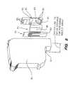
- inkjet printer 10includes an input tray 12 containing sheets of media 14 which pass through a print zone, and are fed past an exit 18 into an output tray 16.
- a movable carriage 20holds print cartridges 22, 24, 26, and 28 which respectively hold yellow (Y), magenta (M), cyan (C) and black (K) inks.
- the front of the carriagehas a support bumper 30 which rides along a guide 32 while the back of the carriage has multiple bushings such as 34 which ride along slide rod 36.
- the position of the carriage as it traverses back and forth across the mediais determined from an encoder strip 38 in order to be sure that the various ink nozzles on each print cartridge are selectively fired at the appropriate time during a carriage scan.
- a 300 dpi color inkjet cartridge 40 having a tab-circuit with a four column thirty-two pad electrical interconnect 42is removably installed in three chutes 44, 46, 48 of a unitary carriage 50.
- a flex-circuit member 52 having three matching sets of conductive pads 54, 56, 58is mounted on flex-frame pins 60 for operative engagement with the cartridge pads when the cartridge is inserted into its appropriate chute.
- An enlarged set of conductive pads 62 covering a larger area, having a different layout, and constituting an array of six columns totaling fifty-two conductive pads on the flex-circuit memberis designed for operative engagement with cartridge pads on a 600 dpi black injet cartridge 64 (see FIG. 9).
- the X-axis cartridge datums 65engage the X-axis carriage datums 66
- the Y-axis cartridge datums 67engage the Y-axis carriage datums 68
- the Z-axis cartridge datums 69engage the Z-axis carriage datums 70 in a manner more fully described in the copending applications identified above.
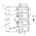
- a previously existing spring assemblyincluding a backing sheet 74, a plate 76 and a gimbal spring 78 are sized for fitting into apertures 80 of flex-circuit frame 82 to assure proper electrical interconnection for the three color cartridges.
- Such resilient structureis described more fully in copending applications identified above.
- a unique spring assembly for the 600 dpi cartridge interconnectincludes an unitary resilient foam member 84 which fits in a seat 86 which is larger than the aperture 80.
- a mounting peg 88fits into matching hole 90 which along with bottom and lower ledges 91, 93 and upper side and top ledges 92, 94 hold the foam member in proper position to assure operative engagement across the electrical interconnect.
- FIGS. 7-8show the preferred mounting relationship between a 300 dpi nozzle array 96 of the color printheads and a 600 dpi nozzle array 98 of the black printhead.
- Control circuitry 99 on the substrateenables the three hundred firing resistors of the black printhead to be controlled through fifty-two electrical interconnect pads, and similarly enables all one hundred four firing resistors of each color printhead to be controlled through thirty-two electrical interconnect pads.
- the multiplexing circuit scheme for such control circuitryis described more fully in copending applications identified above.
- FIG. 12schematically shows the difference between the 300 dpi printout produced by the color pens (i.e., pen cartridges) and the 600 dpi printout of the black pen of the preferred embodiment described herein.
- the resolution differencemay be arbitrary, depending on the printheads available and already developed, or wherein the resolution difference may be decimally related (e.g., 20% greater resolution, 30% greater resolution, etc.) or fractionally related (300dpi with 400 dpi; 300 dpi with 450 dpi, etc.).
- the inventioncan be implemented with any of the existing inkjet cartridges which are currently available, with the best results occurring with printheads in the range of 180 dpi or greater.
- This inventionallows higher resolution and speed to occur for frequently printed features such as text and the most frequent color components of graphics such as black.
- the entire pageis faster and of higher quality and is more comprable with laser printing performance (8+ pages per minute) and laser printing quality (600 dpi resolution).
- the new form of resilient interconnect member disclosed hereinallows for optimization and customization for the particular contact pattern of different cartridges in the same carriage.
- the size of the carriage and the way that the cartridge is held in the carriagehas to change very little between subsequent generations of printers.
- the required design change to the printeris minimized, the carriage does not have to grow wider nor taller, and the printer does not have to grow wider nor taller.
Landscapes
- Engineering & Computer Science (AREA)
- Physics & Mathematics (AREA)
- Quality & Reliability (AREA)
- Mathematical Physics (AREA)
- General Engineering & Computer Science (AREA)
- General Physics & Mathematics (AREA)
- Theoretical Computer Science (AREA)
- Ink Jet (AREA)
- Printers Characterized By Their Purpose (AREA)
Description
- This application is related to copending application docket1093752-1 filed as U.S. Serial No. 08/145367 on October 29, 1993in the name of Gary M. Nobel, et al. entitled INTERCONNECT SCHEMEFOR MOUNTING DIFFERENTLY CONFIGURED PRINTHEADS IN THE SAMECARRIAGE, which application is assigned to the assignee of thisapplication.
- This application also relates to the following copendingapplications which are commonly owned by the assignee of thisapplication, and which are incorporated herein by reference:
- ELECTRICAL INTERCONNECT SYSTEM FOR A PRINTER filed as SerialNo. 08/56,345 on April 30, 1993 in the names of Arthur K. Wilson,et al. (corresponding to EP-A-622 253); MODULAR CARRIAGE ASSEMBLY FOR AN INKJET PRINTER filed asSerial No. 08/55,618 on April 30, 1993 in the names of Arthur K.Wilson, et al. (corresponding to EP-A-622 240); WIPING STRUCTURE FOR CLEANING ELECTRICAL CONTACTSFOR A PRINTER AND INK CARTRIDGE filed as Serial No. 08/56,009 onApril 30, 1993 in the names of Corrina A. E. Hall, et al. ; METHOD AND DEVICE FOR PREVENTING UNINTENDED USE OF PRINT CARTRIDGES filedas Serial No. 08/56,961 on May 3, 1993 in the names of Jeffrey A.Thoman, et al. (corresponding to EP-A-623 471); SIDE BIASED DATUM SCHEME FOR INKJET CARTRIDGE ANDCARRIAGE filed as Serial No. 08/57,241 on April 30, 1993 in thenames of David W. Swanson, et al. (corresponding to EP-A-622 208); and PRINTHEAD WITH REDUCEDINTERCONNECTIONS TO A PRINTER filed as Serial No. 07/958,833 onOctober 8, 1992 in the names of Michael B. Saunders, et al. (corresponding to EP-A-0592221).
- This invention relates generally to printers, and morespecifically to printing devices and techniques for monochrome andcolor printers capable of achieving high quality resolution.
- High quality printers are typically characterized by numbersindicating their resolution in dots per inch (dpi). Thisresolution is usually described in the context of a two dimensioncoordinate system where one number indicates the resolution in thex-axis (as used herein, x-axis means the carriage scan axis for aswath printer), and another number indicates the resolution in they-axis (as used herein, y-axis means the media advance axis for aswath printer). Thus, a resolution of 300/300 dpi generallyindicates a carriage-scan axis resolution of 300 dots per inch anda media-advance axis resolution of 300 dots per inch.
- The resolution of a printhead is primarily determined by theactual printout dot size as it appears in a printout. So in theideal theoretical world, a 300 dpi printhead is presumed to producea printout dot size which is approximately 1/300th inch in diameter. But various common language usages have developed whichdefine resolution in other closely related terms. For example, aprinthead's resolution is often identified by its nozzle pitch(i.e., the distance between adjacent nozzles on a printhead), anda print mode resolution is often identified by its pixeladdressability (i.e., the distance between adjacent pixels in aprintout).
- There are several print mode techniques for expanding theprint quality characteristics of a printhead. For example, a1/300th inch nozzle pitch printhead could be used to create a 600pixel/inch printout in the media-advance axis by changing theincremental advance distance of the media at the end of a swath andthen employing a multi-pass print mode. As another example, a1/300th inch nozzle pitch printhead could be used to create a 600pixel/inch printout in the carriage scan axis by increasing thefiring frequency of the printhead and/or changing the carriage scanspeed.
- However, implementing these different print modes is rathercomplicated and requires sophisticated programming techniques,precisely engineered mechanical parts, and many circuit components.Moreover, the print quality of a lower resolution machine which hasa 300 dpi addressable print mode is not as good as the printquality of a true 600 dpi resolution machine where both smallestdot size and addressability are each equal to 600 dpi.
- JP-A-05 261 941 describes an ink-jet recording head which prints blackdots which are larger than colour dots, a black printhead having a lowerresolution than the colour printhead.
- WO-A-91 089 02 discloses a printhead where the vertical spacing of theblack orifices is less than the vertical spacing of colour orifices. Duringcomposite printing, when both black ink and colour ink are to be deposited onthe same media, every other black orifice is used so that both black and colourare printed at the same vertical resolution.
- JP-A-61 104 856 describes an ink-jet printer which permits simultaneous printing of colour images withoutreducing printing speed of black characters, in which the printhead is provided with more black ink nozzles thancolour ink nozzles.
- WO-A-90 029 25 describes a dual mode ink-jet printer for either high quality or high speed printing. Thespacing between the nozzles in the colour ink arrays is greater than the spacing between the nozzles inthe black ink array.
- It is a primary object of the invention to incorporate multiple resolutioncapabilities directly into the printer printheads in order to expand the capabilitiesof the printer to achieve high quality printing as well as greater throughput. Arelated object is to decrease research and development costs as well asdecrease the time for bringing higher resolution printers to market.
- The present invention is defined in the appended claims.
- A feature of the invention is to provide a printer having higher baseresolution for its black printing component and a lower base resolution for itscolor printing components such as cyan, magenta and yellow. A related objectis to integrate both of the aforesaid black and color printing components into thesame printing mechanism in order to provide composite printing of higherresolution black and lower resolution color at the same time.
- Another important feature of the invention is to provide increasedthroughput for the higher resolution monochrome component of the color printer.In the preferred form, a wider swath monochrome printhead such as a high resolution black printheadwhich produces approximately 600 dpi sized printout dots is mountedon the same carriage as narrower swath color printheads such aslower resolution cyan, magenta and yellow printheads which produceapproximately 300 dpi sized printout dots, with the wider swathblack printhead having overlapping printing alignment with all ofthe narrower swath color printheads. The wider swath blackprinthead has a 300 nozzle swath with a nozzle pitch of 1/600thinch to create a swath of approximately one-half inch, and thenarrower swath color printheads each have a 100 nozzle swath witha nozzle pitch of 1/300th inch to create a swath of approximatelyone-third inch.
- FIG. 1 shows a typical inkjet printer which can incorporatethe apparatus and method of the present invention;
- FIG. 2 shows a carriage having removable multi-color printcartridges, which can incorporated the apparatus and method of thepresent invention;
- FIG. 3 shows an exemplary lower resolution color inkjet printcartridge used in a presently preferred embodiment of theinvention;
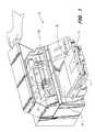
- FIG. 4 is a perspective view of a carriage incorporatingpresently preferred embodiment of the invention in an inkjetprinter;
- FIG. 5 is a top view of the carriage of FIG. 4;
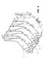
- FIG. 6 is a fragmentary view of the flex-circuit interconnecton the carriage of FIGS. 4 and 5, with the interior carriage wallscut away;
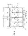
- FIG. 7 is a schematic block diagram of the presently preferredembodiment of the invention;
- FIG. 8 is a schematic bottom view as seen looking up from themedia showing the alignment relationship of the nozzle arrays ofFIG. 7;
- FIG. 9 is a schematic view showing the use of a foam memberfor operatively connecting a flex-circuit to a higher resolutionblack inkjet cartridge;
- FIG. 10 is an exploded view showing a flex-circuit frameportion of a carriage, with the foam spring member of FIG. 9 forassuring pressure connection of a flex-circuit to a higherresolution black inkjet cartridge, and a metal spring member forassuring pressure connection of a flex-circuit to lower resolutioncolor inkjet cartridges;
- FIG. 11 is a front view of the flex-circuit frame of FIG. 10;and
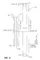
- FIG. 12 is a schematic diagram showing the relative resolutionbetween a 600 dpi printout of the black printheads and a 300 dpiprintout of the color printheads of a presently preferredembodiment of the invention.
- In a multiple pen printer, it is important to improve theoutput quality of a printed page and increase the speed at whichthat output can be obtained as economically and simply as possible.In a printer mechanism, the output quality of a printed page is afunction of printhead resolution. The higher the resolution thebetter the print quality. Also, in a swath printer employing ascanning carriage, the speed at which the output can be obtained isa function of the width of the swath which is covered by theprinthead.
- In current multi-pen printers, each pen has the sameresolution and usually the same swath width. This means that allthe supporting structure, mechanics and electronics needs to bescaled up to support the resolution of the entire set of pens. Allthis hardware is more expensive than the hardware to support amulti-resolution, multi-swath width pen set where one pen is at thehigher resolution and larger width that is desired and the otherpens in the set are at a lower resolution and smaller size.
- This invention provides the benefits of a higher resolution,larger swath pen in lower resolution, smaller swath pens in thesame printing machine. The higher performance pen can be used toimprove output quality by enhancing certain key features thatappear frequently in a printed page such as text. Such a pen alsoimproves thoughput by being able to print these frequent featuresfaster. The other lower performance pens can be used for lessfrequent or less demanding features such as graphics.
- In the presently preferred embodiment of the inventiondisclosed herein, we have combined a 600
dpi 1/2 inch swath blackpen with three 300 dpi color pens each generating a swath ofapproximately 1/3 inch. The high performance black pen istypically used for printing text and other "black only" features,and thus the output quality and throughput of these features isgreater. It also improves the output quality of color graphics andcolor features by teaming with the three lower performance colorpens when printing color graphics or color features. The blackcomponent of the graphics which is often a large portion of colorgraphics content is at a higher resolution and thus at a higheroutput quality level. The larger swath can then be combined withprinting algorithms to improve the throughput of color graphics. - Even though the invention can be used in any printingenvironment where text and/or graphics are applied to media usingmonochrome and/or color comoponents, the presently preferredembodiment of the invention is used in an inkjet printer of thetype shown in FIG. 1. In particular,
inkjet printer 10 includes aninput tray 12 containing sheets ofmedia 14 which pass through aprint zone, and are fed past anexit 18 into anoutput tray 16.Referring to FIGS. 1-2, amovable carriage 20 holdsprintcartridges support bumper 30 which rides along aguide 32 whilethe back of the carriage has multiple bushings such as 34 whichride alongslide rod 36. The position of the carriage as it traverses back and forth across the media is determined from anencoder strip 38 in order to be sure that the various ink nozzleson each print cartridge are selectively fired at the appropriatetime during a carriage scan. - Referring to FIGS. 3-6, a 300 dpi
color inkjet cartridge 40having a tab-circuit with a four column thirty-two padelectricalinterconnect 42 is removably installed in threechutes unitary carriage 50. A flex-circuit member 52 having threematching sets ofconductive pads conductive pads 62 covering a larger area, having adifferent layout, and constituting an array of six columns totalingfifty-two conductive pads on the flex-circuit member is designedfor operative engagement with cartridge pads on a 600 dpi blackinjet cartridge 64 (see FIG. 9). - The preferred structure and techniques for preventing mistakeninstallation of a 600 dpi black printhead in a color printheadchute, or alternatively the mistaken installation of a 300 dpicolor printhead in a black printhead chute is described in thecopending applications identified above.
- Because of the differently configured electrical interconnecton the 600 dpi cartridge, and in order to avoid substantiallychanging the existing X/Y/Z datum configuration of the carriage, aunique interconnect scheme is employed. In that regard, the
X-axis cartridge datums 65 engage theX-axis carriage datums 66, and theY-axis cartridge datums 67 engage the Y-axis carriage datums 68,and the Z-axis cartridge datums 69 engage the Z-axis carriagedatums 70 in a manner more fully described in the copendingapplications identified above. - As best shown in FIGS. 9-11, a previously existing springassembly including a
backing sheet 74, aplate 76 and a gimbalspring 78 are sized for fitting intoapertures 80 of flex-circuitframe 82 to assure proper electrical interconnection for the threecolor cartridges. Such resilient structure is described more fullyin copending applications identified above. - A unique spring assembly for the 600 dpi cartridgeinterconnect includes an unitary
resilient foam member 84 whichfits in aseat 86 which is larger than theaperture 80. A mountingpeg 88 fits into matchinghole 90 which along with bottom andlowerledges top ledges - FIGS. 7-8 show the preferred mounting relationship between a300
dpi nozzle array 96 of the color printheads and a 600dpinozzle array 98 of the black printhead.Control circuitry 99 on the substrate enables the three hundred firing resistors of theblack printhead to be controlled through fifty-two electricalinterconnect pads, and similarly enables all one hundred fourfiring resistors of each color printhead to be controlled throughthirty-two electrical interconnect pads. The multiplexing circuitscheme for such control circuitry is described more fully incopending applications identified above. - FIG. 12 schematically shows the difference between the 300 dpiprintout produced by the color pens (i.e., pen cartridges) and the600 dpi printout of the black pen of the preferred embodimentdescribed herein. Of course, it would be possible to incorporateddifferent combinations of resolution in different printheadswherein the resolution difference may be arbitrary, depending onthe printheads available and already developed, or wherein theresolution difference may be decimally related (e.g., 20% greaterresolution, 30% greater resolution, etc.) or fractionally related(300dpi with 400 dpi; 300 dpi with 450 dpi, etc.). In that regard,the invention can be implemented with any of the existing inkjetcartridges which are currently available, with the best resultsoccurring with printheads in the range of 180 dpi or greater.
- It will therefore be appreciated by those skilled in the artthat the invention as shown and described herein allows differenttypes of interconnects and different types of print cartridges suchas cartridges of different print resolutions to be used in oneproduct.
- This invention allows higher resolution and speed to occur forfrequently printed features such as text and the most frequentcolor components of graphics such as black. Thus by printing thesefrequent features and components faster and at a higher resolution,the entire page is faster and of higher quality and is morecomprable with laser printing performance (8+ pages per minute) andlaser printing quality (600 dpi resolution).
- The new form of resilient interconnect member disclosed hereinallows for optimization and customization for the particularcontact pattern of different cartridges in the same carriage.Thus, the size of the carriage and the way that the cartridge isheld in the carriage has to change very little between subsequentgenerations of printers. In other words, the required designchange to the printer is minimized, the carriage does not have togrow wider nor taller, and the printer does not have to grow widernor taller.
Claims (9)
- A mixed resolution printer (10) comprising:a frame for holding a media in a print zone;a carriage (50) supported on said frame to bepositioned adjacent to said print zone;a first printhead (64) supported by said carriage, saidfirst printhead having a first array of nozzles (98) extending in a substantially perpendicular direction to the direction of movement of said first printhead relative to said media forejecting black ink droplets having a first drop size and having a first vertical printresolution;a second printhead (40) supported by said carriage in aside-by-side relationship with said first printhead, saidsecond printhead having a second array of nozzles (96) extending in a substantially perpendicular direction to the direction of movement of said second printhead relative to said media forejecting non-black color ink droplets having a second dropsize substantially larger than said first drop size and having a secondvertical print resolution lower than said first verticalprint resolution; andmeans (50, 41, 99) for energizing ink ejection elementsin said first and second printheads such that said firstprinthead prints said black ink droplets at said firstvertical print resolution and said second printhead printssaid color ink droplets at said second vertical printresolution for composite printing by said first and secondprintheads on the media in said print zone.
- A printer according to claim 1 wherein said secondprinthead includes a color component selected from cyan, magenta,yellow, red, green and blue.
- A printer according to claim 1 or 2 wherein said firstprinthead has a wider printing swath than said second printhead.
- A printer according to claim 1 wherein said first arrayof nozzles has a first nozzle pitch, and said second array ofnozzles has a second nozzle pitch, with said first nozzle pitch less than said second nozzle pitch as measured in a media advanceaxis.
- A printer according to any preceding claim wherein saidfirst and second printheads are mounted in said carriage inrelative positions along the media advance axis in order toproduce at least partially overlapping print swaths from saidfirst and second printheads.
- A printer according to any preceding claim wherein saidsecond printhead is mounted in said carriage to be in completelyoverlapped printing alignment with said first printhead.
- A printer according to any preceding claim wherein saidfirst printhead prints at a resolution of 600 dots per inch andsaid second printhead prints at a resolution of 300 dots perinch.
- A printer according to any preceding claim furthercomprising a third printhead (22) and a fourth printhead (24)supported by said carriage, said third and fourth printheadsbeing identical to said second printhead, but printing differentcolors of ink.
- A printer according to any preceding claim wherein said firstprinthead is mounted in a print cartridge separate from a print cartridgein which is mounted said second printhead.
Applications Claiming Priority (2)
| Application Number | Priority Date | Filing Date | Title |
|---|---|---|---|
| US08/145,261US5949453A (en) | 1993-10-29 | 1993-10-29 | Mixed resolution printing for color and monochrome printers |
| US145261 | 1993-10-29 |
Publications (3)
| Publication Number | Publication Date |
|---|---|
| EP0654352A2 EP0654352A2 (en) | 1995-05-24 |
| EP0654352A3 EP0654352A3 (en) | 1996-06-05 |
| EP0654352B1true EP0654352B1 (en) | 2001-01-03 |
Family
ID=22512295
Family Applications (1)
| Application Number | Title | Priority Date | Filing Date |
|---|---|---|---|
| EP94307806AExpired - LifetimeEP0654352B1 (en) | 1993-10-29 | 1994-10-25 | Mixed resolution printing for colour and monochrome printers |
Country Status (9)
| Country | Link |
|---|---|
| US (1) | US5949453A (en) |
| EP (1) | EP0654352B1 (en) |
| JP (1) | JP3588151B2 (en) |
| KR (1) | KR100342297B1 (en) |
| CN (1) | CN1071196C (en) |
| CA (1) | CA2132470C (en) |
| DE (1) | DE69426519T2 (en) |
| ES (1) | ES2152970T3 (en) |
| TW (1) | TW267977B (en) |
Families Citing this family (36)
| Publication number | Priority date | Publication date | Assignee | Title |
|---|---|---|---|---|
| JPH08244287A (en)* | 1995-03-06 | 1996-09-24 | Hewlett Packard Co <Hp> | Printer that has printing zone height of composite |
| US5793388A (en)* | 1995-03-06 | 1998-08-11 | Hewlett-Packard Company | Customized printhead servicing for different printer conditions |
| US5886714A (en)* | 1995-03-06 | 1999-03-23 | Hewlett-Packard Company | Actuation mechanism for translational wiping of a stationary inkjet printhead |
| US6543884B1 (en)* | 1996-02-07 | 2003-04-08 | Hewlett-Packard Company | Fully integrated thermal inkjet printhead having etched back PSG layer |
| JPH1067127A (en)* | 1996-04-23 | 1998-03-10 | Canon Inc | Ink jet recording apparatus and image processing method |
| JP3576694B2 (en)* | 1996-04-23 | 2004-10-13 | キヤノン株式会社 | Ink jet recording method, apparatus thereof, image processing method, and printing method for executing image processing method |
| DE69725043T2 (en) | 1996-04-23 | 2004-07-08 | Canon K.K. | Ink jet printing system, method and apparatus for ink jet printing |
| JPH09286125A (en)* | 1996-04-23 | 1997-11-04 | Canon Inc | Ink jet recording method and apparatus |
| JP3413052B2 (en)* | 1996-04-23 | 2003-06-03 | キヤノン株式会社 | Ink jet recording apparatus and control method |
| US6682170B2 (en)* | 1997-04-07 | 2004-01-27 | Minolta Co., Ltd. | Image forming apparatus |
| JP3490873B2 (en)* | 1997-10-03 | 2004-01-26 | フーリエ有限会社 | Printing equipment |
| US6359701B1 (en)* | 1997-11-17 | 2002-03-19 | Canon Kabushiki Kaisha | Multi-head printing with differing resolutions |
| JPH11320924A (en) | 1998-03-13 | 1999-11-24 | Canon Inc | Image recording apparatus, control method thereof, and recording apparatus |
| JP2000071482A (en)* | 1998-08-28 | 2000-03-07 | Toshiba Tec Corp | Color inkjet printer |
| CN1216741C (en)* | 1999-06-30 | 2005-08-31 | 佳能精技股份有限公司 | inkjet image forming device |
| JP2001010081A (en) | 1999-06-30 | 2001-01-16 | Canon Inc | Ink jet cartridge, ink jet device, and method of manufacturing ink jet cartridge |
| US6585347B1 (en) | 2000-01-31 | 2003-07-01 | Hewlett-Packard Company | Printhead servicing based on relocating stationary print cartridges away from print zone |
| US6595612B1 (en) | 2000-02-23 | 2003-07-22 | Mutoh Industries Ltd. | Inkjet printer capable of minimizing chromatic variation in adjacent print swaths when printing color images in bidirectional model |
| US6273550B1 (en) | 2000-02-23 | 2001-08-14 | Mutoh Industries Inc. | Inkjet printer capable of minimizing chromatic variation in adjacent print swaths when printing color images in bidirectional mode |
| US6659591B2 (en)* | 2000-07-10 | 2003-12-09 | Canon Kabushiki Kaisha | Ink jet recording head and producing method for the same |
| US6798538B1 (en)* | 2000-09-08 | 2004-09-28 | Canon Kabushiki Kaisha | Halftoning at multiple different resolutions |
| US6776468B2 (en)* | 2001-08-27 | 2004-08-17 | Eastman Kodak Company | Method and apparatus of optimizing discrete drop volumes for multidrop capable inkjet printers |
| US6663215B2 (en)* | 2001-10-25 | 2003-12-16 | Hewlett-Packard Company, L.P. | Printhead service station |
| KR20030035514A (en)* | 2001-10-31 | 2003-05-09 | 삼성전자주식회사 | InkJet printer capable of optionally mounting cartridge and method for identifying the cartridge |
| US7369267B2 (en)* | 2003-06-30 | 2008-05-06 | Lexmark International, Inc. | High resolution printing method |
| JP4307319B2 (en) | 2004-04-30 | 2009-08-05 | キヤノン株式会社 | Recording apparatus and recording method |
| CN100493915C (en)* | 2004-05-20 | 2009-06-03 | 光宝科技股份有限公司 | Printing method with double resolution |
| US7140710B2 (en)* | 2004-06-28 | 2006-11-28 | Lexmark International, Inc. | Dot management for an imaging apparatus |
| US8441474B2 (en) | 2008-06-25 | 2013-05-14 | Aristocrat Technologies Australia Pty Limited | Method and system for setting display resolution |
| KR101601156B1 (en)* | 2008-06-30 | 2016-03-08 | 후지필름 디마틱스, 인크. | Ink jetting |
| US8405840B2 (en)* | 2008-12-18 | 2013-03-26 | Sharp Laboratories Of America, Inc. | Systems and methods for minimizing re-imaging procedures for an imaging device |
| US8300269B2 (en)* | 2009-03-30 | 2012-10-30 | Eastman Kodak Company | Dot forming element arrays at different resolutions |
| JP5702621B2 (en) | 2011-02-10 | 2015-04-15 | 株式会社Screenホールディングス | Image recording apparatus and image recording method |
| JP2015066813A (en)* | 2013-09-30 | 2015-04-13 | 理想科学工業株式会社 | Inkjet printing device |
| CN103481695B (en)* | 2013-10-14 | 2015-05-27 | 深圳市巨鼎医疗设备有限公司 | Method for printing medical black-white and colorful mixed image |
| KR20190021335A (en) | 2016-07-21 | 2019-03-05 | 인트러스트 데이타카드 코포레이션 | A printhead that divides the print job |
Family Cites Families (18)
| Publication number | Priority date | Publication date | Assignee | Title |
|---|---|---|---|---|
| JPS5971865A (en)* | 1982-10-19 | 1984-04-23 | Nec Corp | Color ink jet printer |
| JPS61104856A (en)* | 1984-10-29 | 1986-05-23 | Nec Corp | Ink jet color print head |
| JPH0755560B2 (en)* | 1985-05-09 | 1995-06-14 | シャープ株式会社 | Inkjet printer |
| US4709246A (en)* | 1986-12-22 | 1987-11-24 | Eastman Kodak Company | Adjustable print/cartridge ink jet printer |
| JPH01208143A (en)* | 1988-02-17 | 1989-08-22 | Canon Inc | Color ink jet printer head arrangement structure |
| JP2710943B2 (en)* | 1988-02-26 | 1998-02-10 | キヤノン株式会社 | Inkjet printer |
| US4864328A (en)* | 1988-09-06 | 1989-09-05 | Spectra, Inc. | Dual mode ink jet printer |
| US5075689A (en)* | 1989-05-31 | 1991-12-24 | Spectra, Inc. | Bidirectional hot melt ink jet printing |
| JP2859296B2 (en)* | 1989-06-01 | 1999-02-17 | キヤノン株式会社 | Image reproducing method and apparatus |
| DE8906890U1 (en)* | 1989-06-05 | 1990-07-12 | Siemens AG, 1000 Berlin und 8000 München | Print head for inkjet printer |
| US5012257A (en)* | 1990-03-16 | 1991-04-30 | Hewlett-Packard Company | Ink jet color graphics printing |
| CA2049571C (en)* | 1990-10-19 | 2004-01-13 | Kent D. Vincent | High definition thermal ink-jet printer |
| US5208605A (en)* | 1991-10-03 | 1993-05-04 | Xerox Corporation | Multi-resolution roofshooter printheads |
| JPH05261941A (en)* | 1992-03-18 | 1993-10-12 | Ricoh Co Ltd | Inkjet recording method and inkjet recording head |
| US5376958A (en)* | 1992-05-01 | 1994-12-27 | Hewlett-Packard Company | Staggered pens in color thermal ink-jet printer |
| US5512923A (en)* | 1992-09-30 | 1996-04-30 | Hewlett-Packard Company | Color variation control method for ink-jet printers |
| US5412410A (en)* | 1993-01-04 | 1995-05-02 | Xerox Corporation | Ink jet printhead for continuous tone and text printing |
| US5404020A (en)* | 1993-04-30 | 1995-04-04 | Hewlett-Packard Company | Phase plate design for aligning multiple inkjet cartridges by scanning a reference pattern |
- 1993
- 1993-10-29USUS08/145,261patent/US5949453A/ennot_activeExpired - Lifetime
- 1994
- 1994-09-17TWTW083108624Apatent/TW267977B/zhnot_activeIP Right Cessation
- 1994-09-20CACA002132470Apatent/CA2132470C/ennot_activeExpired - Fee Related
- 1994-10-25JPJP28419894Apatent/JP3588151B2/ennot_activeExpired - Fee Related
- 1994-10-25DEDE69426519Tpatent/DE69426519T2/ennot_activeExpired - Fee Related
- 1994-10-25EPEP94307806Apatent/EP0654352B1/ennot_activeExpired - Lifetime
- 1994-10-25ESES94307806Tpatent/ES2152970T3/ennot_activeExpired - Lifetime
- 1994-10-28CNCN94113782Apatent/CN1071196C/ennot_activeExpired - Fee Related
- 1994-10-28KRKR1019940027963Apatent/KR100342297B1/ennot_activeExpired - Fee Related
Also Published As
| Publication number | Publication date |
|---|---|
| EP0654352A2 (en) | 1995-05-24 |
| JPH07186411A (en) | 1995-07-25 |
| JP3588151B2 (en) | 2004-11-10 |
| US5949453A (en) | 1999-09-07 |
| TW267977B (en) | 1996-01-11 |
| EP0654352A3 (en) | 1996-06-05 |
| KR960013662A (en) | 1996-05-22 |
| CA2132470A1 (en) | 1995-04-30 |
| KR100342297B1 (en) | 2002-11-29 |
| CN1071196C (en) | 2001-09-19 |
| DE69426519D1 (en) | 2001-02-08 |
| CN1113184A (en) | 1995-12-13 |
| CA2132470C (en) | 2004-03-09 |
| DE69426519T2 (en) | 2001-05-17 |
| ES2152970T3 (en) | 2001-02-16 |
Similar Documents
| Publication | Publication Date | Title |
|---|---|---|
| EP0654352B1 (en) | Mixed resolution printing for colour and monochrome printers | |
| US5684518A (en) | Interconnect scheme for mounting differently configured printheads on the same carriage | |
| US5971524A (en) | Alignment of differently sized printheads in a printer | |
| US5541625A (en) | Method for increased print resolution in the carriage scan axis of an inkjet printer | |
| EP0730968B1 (en) | Resolution-dependent and color-dependent print masking | |
| US4750009A (en) | Color ink jet system printer capable of high definition printing | |
| EP0863004B2 (en) | Dynamic multi-pass print mode corrections to compensate for malfunctioning inkjet nozzles | |
| EP0730967B1 (en) | Simultaneously printing with different sections of printheads for improved print quality | |
| US4630076A (en) | Ink-on-demand color ink jet system printer | |
| US4728968A (en) | Arrangement of discharge openings in a printhead of a multi-color ink printer | |
| US5975679A (en) | Dot alignment in mixed resolution printer | |
| US5912683A (en) | Method of printing with an ink jet printer using an enhanced horizontal resolution | |
| US6244687B1 (en) | Mixing overprinting and underprinting of inks in an inkjet printer to speed up the dry time of black ink without undesirable hue shifts | |
| US6017113A (en) | Mixed-density print masking in a mixed-swath-height printer | |
| US5796417A (en) | Compliant interconnect assembly for mounting removable print cartridges in a carriage | |
| EP0730969B1 (en) | Dot alignment in mixed resolution printer | |
| US6270185B1 (en) | Very-high-ratio mixed resolution and biphod pens for low-cost fast bidirectional one-pass incremental printing | |
| CA2374461A1 (en) | Method of printing with an ink jet printer using multiple carriage speeds | |
| EP0836946B1 (en) | Ink jet printhead for high definition printing and method for operating same | |
| KR20020036948A (en) | Method for formation of colours with a colour printer | |
| JPH1158705A (en) | Recorder | |
| MXPA98006865A (en) | Printing method with an ink jet printer using a better horizontal resolution |
Legal Events
| Date | Code | Title | Description |
|---|---|---|---|
| PUAI | Public reference made under article 153(3) epc to a published international application that has entered the european phase | Free format text:ORIGINAL CODE: 0009012 | |
| AK | Designated contracting states | Kind code of ref document:A2 Designated state(s):DE ES FR GB IT | |
| RIN1 | Information on inventor provided before grant (corrected) | Inventor name:NOBEL, GARY M. Inventor name:AZMOON, MAJID Inventor name:HARRIS, DONALD G. | |
| PUAL | Search report despatched | Free format text:ORIGINAL CODE: 0009013 | |
| RHK1 | Main classification (correction) | Ipc:B41J 2/21 | |
| AK | Designated contracting states | Kind code of ref document:A3 Designated state(s):DE ES FR GB IT | |
| 17P | Request for examination filed | Effective date:19961107 | |
| 17Q | First examination report despatched | Effective date:19981019 | |
| GRAG | Despatch of communication of intention to grant | Free format text:ORIGINAL CODE: EPIDOS AGRA | |
| 17Q | First examination report despatched | Effective date:19981019 | |
| GRAG | Despatch of communication of intention to grant | Free format text:ORIGINAL CODE: EPIDOS AGRA | |
| GRAH | Despatch of communication of intention to grant a patent | Free format text:ORIGINAL CODE: EPIDOS IGRA | |
| GRAH | Despatch of communication of intention to grant a patent | Free format text:ORIGINAL CODE: EPIDOS IGRA | |
| GRAA | (expected) grant | Free format text:ORIGINAL CODE: 0009210 | |
| AK | Designated contracting states | Kind code of ref document:B1 Designated state(s):DE ES FR GB IT | |
| REF | Corresponds to: | Ref document number:69426519 Country of ref document:DE Date of ref document:20010208 | |
| REG | Reference to a national code | Ref country code:ES Ref legal event code:FG2A Ref document number:2152970 Country of ref document:ES Kind code of ref document:T3 | |
| ET | Fr: translation filed | ||
| ITF | It: translation for a ep patent filed | ||
| RAP2 | Party data changed (patent owner data changed or rights of a patent transferred) | Owner name:HEWLETT-PACKARD COMPANY, A DELAWARE CORPORATION | |
| PLBE | No opposition filed within time limit | Free format text:ORIGINAL CODE: 0009261 | |
| STAA | Information on the status of an ep patent application or granted ep patent | Free format text:STATUS: NO OPPOSITION FILED WITHIN TIME LIMIT | |
| REG | Reference to a national code | Ref country code:GB Ref legal event code:IF02 | |
| 26N | No opposition filed | ||
| REG | Reference to a national code | Ref country code:GB Ref legal event code:732E | |
| REG | Reference to a national code | Ref country code:ES Ref legal event code:PC2A | |
| REG | Reference to a national code | Ref country code:FR Ref legal event code:TP | |
| PGFP | Annual fee paid to national office [announced via postgrant information from national office to epo] | Ref country code:DE Payment date:20070228 Year of fee payment:13 | |
| PGFP | Annual fee paid to national office [announced via postgrant information from national office to epo] | Ref country code:ES Payment date:20071026 Year of fee payment:14 | |
| PGFP | Annual fee paid to national office [announced via postgrant information from national office to epo] | Ref country code:IT Payment date:20071030 Year of fee payment:14 | |
| PGFP | Annual fee paid to national office [announced via postgrant information from national office to epo] | Ref country code:FR Payment date:20070207 Year of fee payment:13 | |
| PG25 | Lapsed in a contracting state [announced via postgrant information from national office to epo] | Ref country code:DE Free format text:LAPSE BECAUSE OF NON-PAYMENT OF DUE FEES Effective date:20080501 | |
| REG | Reference to a national code | Ref country code:FR Ref legal event code:ST Effective date:20080630 | |
| PG25 | Lapsed in a contracting state [announced via postgrant information from national office to epo] | Ref country code:FR Free format text:LAPSE BECAUSE OF NON-PAYMENT OF DUE FEES Effective date:20071031 | |
| PG25 | Lapsed in a contracting state [announced via postgrant information from national office to epo] | Ref country code:IT Free format text:LAPSE BECAUSE OF NON-PAYMENT OF DUE FEES Effective date:20081025 | |
| REG | Reference to a national code | Ref country code:ES Ref legal event code:FD2A Effective date:20081027 | |
| PG25 | Lapsed in a contracting state [announced via postgrant information from national office to epo] | Ref country code:ES Free format text:LAPSE BECAUSE OF NON-PAYMENT OF DUE FEES Effective date:20081027 | |
| REG | Reference to a national code | Ref country code:GB Ref legal event code:732E Free format text:REGISTERED BETWEEN 20120329 AND 20120404 | |
| PGFP | Annual fee paid to national office [announced via postgrant information from national office to epo] | Ref country code:GB Payment date:20121025 Year of fee payment:19 | |
| GBPC | Gb: european patent ceased through non-payment of renewal fee | Effective date:20131025 | |
| PG25 | Lapsed in a contracting state [announced via postgrant information from national office to epo] | Ref country code:GB Free format text:LAPSE BECAUSE OF NON-PAYMENT OF DUE FEES Effective date:20131025 |