EP0653335B1 - Apparatus for restraining an occupant of a vehicle upon a side impact against the vehicle - Google Patents
Apparatus for restraining an occupant of a vehicle upon a side impact against the vehicleDownload PDFInfo
- Publication number
- EP0653335B1 EP0653335B1EP94308039AEP94308039AEP0653335B1EP 0653335 B1EP0653335 B1EP 0653335B1EP 94308039 AEP94308039 AEP 94308039AEP 94308039 AEP94308039 AEP 94308039AEP 0653335 B1EP0653335 B1EP 0653335B1
- Authority
- EP
- European Patent Office
- Prior art keywords
- occupant
- vehicle
- restraint means
- inflated
- shoulder
- Prior art date
- Legal status (The legal status is an assumption and is not a legal conclusion. Google has not performed a legal analysis and makes no representation as to the accuracy of the status listed.)
- Expired - Lifetime
Links
- 230000000452restraining effectEffects0.000titledescription6
- 239000012530fluidSubstances0.000claimsdescription21
- 230000001419dependent effectEffects0.000claims1
- 239000007789gasSubstances0.000description9
- 208000027418Wounds and injuryDiseases0.000description7
- 230000006378damageEffects0.000description7
- 208000014674injuryDiseases0.000description7
- 239000000463materialSubstances0.000description5
- 230000003187abdominal effectEffects0.000description4
- 238000010276constructionMethods0.000description2
- 230000003111delayed effectEffects0.000description2
- 238000000034methodMethods0.000description2
- 238000012986modificationMethods0.000description2
- 230000004048modificationEffects0.000description2
- 239000000853adhesiveSubstances0.000description1
- 230000001070adhesive effectEffects0.000description1
- 230000002238attenuated effectEffects0.000description1
- 230000004886head movementEffects0.000description1
- 239000011261inert gasSubstances0.000description1
- 239000011148porous materialSubstances0.000description1
- 238000009958sewingMethods0.000description1
Images


Classifications
- B—PERFORMING OPERATIONS; TRANSPORTING
- B60—VEHICLES IN GENERAL
- B60R—VEHICLES, VEHICLE FITTINGS, OR VEHICLE PARTS, NOT OTHERWISE PROVIDED FOR
- B60R21/00—Arrangements or fittings on vehicles for protecting or preventing injuries to occupants or pedestrians in case of accidents or other traffic risks
- B60R21/02—Occupant safety arrangements or fittings, e.g. crash pads
- B60R21/16—Inflatable occupant restraints or confinements designed to inflate upon impact or impending impact, e.g. air bags
- B60R21/23—Inflatable members
- B60R21/231—Inflatable members characterised by their shape, construction or spatial configuration
- B60R21/23138—Inflatable members characterised by their shape, construction or spatial configuration specially adapted for side protection
- B—PERFORMING OPERATIONS; TRANSPORTING
- B60—VEHICLES IN GENERAL
- B60R—VEHICLES, VEHICLE FITTINGS, OR VEHICLE PARTS, NOT OTHERWISE PROVIDED FOR
- B60R21/00—Arrangements or fittings on vehicles for protecting or preventing injuries to occupants or pedestrians in case of accidents or other traffic risks
- B60R21/02—Occupant safety arrangements or fittings, e.g. crash pads
- B60R21/16—Inflatable occupant restraints or confinements designed to inflate upon impact or impending impact, e.g. air bags
- B60R21/20—Arrangements for storing inflatable members in their non-use or deflated condition; Arrangement or mounting of air bag modules or components
- B60R21/21—Arrangements for storing inflatable members in their non-use or deflated condition; Arrangement or mounting of air bag modules or components in vehicle side panels, e.g. doors
- B—PERFORMING OPERATIONS; TRANSPORTING
- B60—VEHICLES IN GENERAL
- B60R—VEHICLES, VEHICLE FITTINGS, OR VEHICLE PARTS, NOT OTHERWISE PROVIDED FOR
- B60R21/00—Arrangements or fittings on vehicles for protecting or preventing injuries to occupants or pedestrians in case of accidents or other traffic risks
- B60R21/02—Occupant safety arrangements or fittings, e.g. crash pads
- B60R21/16—Inflatable occupant restraints or confinements designed to inflate upon impact or impending impact, e.g. air bags
- B60R21/20—Arrangements for storing inflatable members in their non-use or deflated condition; Arrangement or mounting of air bag modules or components
- B60R21/215—Arrangements for storing inflatable members in their non-use or deflated condition; Arrangement or mounting of air bag modules or components characterised by the covers for the inflatable member
- B60R21/216—Arrangements for storing inflatable members in their non-use or deflated condition; Arrangement or mounting of air bag modules or components characterised by the covers for the inflatable member comprising tether means for limitation of cover motion during deployment
- B60R2021/2161—Arrangements for storing inflatable members in their non-use or deflated condition; Arrangement or mounting of air bag modules or components characterised by the covers for the inflatable member comprising tether means for limitation of cover motion during deployment the cover being displaced towards the occupant during deployment
Definitions
- the present inventionrelates to a method and apparatus for protecting an occupant of a vehicle upon a collision or the like, and is particularly directed to a method and apparatus for restraining an occupant of a vehicle upon a side impact against the vehicle.
- a vehicle occupant restraint for protecting an occupant of a vehicle upon a side impact against the vehicleis known.
- a vehicle occupant restraintincludes an inflatable air bag and a source of inflation fluid for inflating the air bag, both of which are mounted on a vehicle door.
- the source of inflation fluidprovides inflation fluid to inflate the air bag.
- the inflated air bagrestrains movement of the occupant and prevents the occupant from violently striking parts of the vehicle during a side impact against the vehicle.
- a one-piece side impact air bagis known from JP-A-51 62598. This document discloses an airbag having a horizontal portion and a vertical portion.
- DE-A-4,119,788discloses a vehicle occupant restraint located on the side of a vehicle.
- DE-A-2,222,621discloses an airbag comprising a plurality of compartments.
- a vehicle occupant shoulder restraint meansis located on a vehicle side, such as on the vehicle door, and is inflatable from a stored condition to an inflated condition between the vehicle side and the shoulder area of an occupant of the vehicle. When inflated, the vehicle occupant shoulder restraint means engages the shoulder of the occupant.
- a vehicle occupant upper rib restraint means separate from the shoulder restraint meansis also located on the vehicle side and is inflatable from a stored condition to an inflated condition between the vehicle side and the upper rib area of the occupant. When inflated, the vehicle occupant upper rib restraint means engages the upper rib area of the occupant.
- Sensor meansis provided for sensing a side impact against the vehicle.
- Meansis provided for directing inflation fluid into the vehicle occupant shoulder restraint means and the vehicle occupant upper rib restraint means when a side impact against the vehicle is sensed by the sensor means.
- the occupant shoulder restraint meanshas an innermost occupant contact point in the passenger compartment which lies in a first vertical plane extending in the forward and rearward directions of travel of the vehicle when the occupant shoulder restraint means is inflated.
- the occupant upper rib restraint meanshas an innermost occupant contact point in the passenger compartment which lies in a second vertical plane extending in the forward and rearward directions of travel of the vehicle when the occupant upper rib restraint means is inflated.
- the first and second vertical planeslie parallel with a central vertical plane which extends in the forward and rearward directions of travel of the vehicle and divides the vehicle in half in the forward and rearward directions of travel of the vehicle. The first vertical plane lies closer in distance to the central vertical plane than the second vertical plane.
- the innermost occupant contact point of the occupant shoulder restraint meansis closer to the occupant than the innermost occupant contact point of the occupant upper rib restraint means when the occupant shoulder restraint means and the occupant upper rib restraint means are inflated.
- an apparatus for use in a vehicle having a passenger compartment and a vehicle front, rear, and side, and a central vertical plane extending in the forward and rearward directions of travel of the vehicle and dividing the vehicle in half in said forward and rearward directions of travelcomprises:
- the probability of the shoulder of the occupant engaging the occupant shoulder restraint means before the upper rib area of the occupant engages the occupant upper rib restraint meansis higher than otherwise.
- the shoulder of the occupantis more likely to be restrained by the inflating occupant shoulder restraint means before the upper rib area of the occupant is restrained by the inflating occupant upper rib restraint means.
- the shoulder structure of a humancan withstand higher loads and deflections than the upper rib area of a human.
- the upper rib areacan withstand higher loads and deflections than the lowest rib area (abdominal ribs) of a human.
- the lowest rib areais more prone to injury than the upper rib area which, in turn, is more prone to injury than the shoulder structure of a human.
- the vehicle occupant restraint meansmay also include an inflatable portion for, when inflated, engaging the head of the occupant.
- the time at which the head of the occupant is engagedis delayed relative to the time at which the shoulder of the occupant is engaged by the inflating occupant shoulder restraint means.
- An advantageresults from restraining the head of an occupant by an occupant restraint means later than when the shoulder of the occupant is restrained. Specifically, during a side impact against the vehicle, the torso may move out from under the head, causing the head to rotate toward the side of the vehicle which was impacted. By delaying the time at which the head of the occupant is engaged and restrained by a third portion of the vehicle occupant restraint means relative to the time at which the shoulder of the occupant is engaged by a first portion of the vehicle occupant restraint means, the occupant is optimally protected against injury to the head as well as the torso.
- the present inventionis directed to an inflatable vehicle occupant restraint apparatus to restrain movement of an occupant of a vehicle upon a side impact against the vehicle.
- the specific construction of the occupant restraint apparatusmay vary.
- an inflatable vehicle occupant restraint apparatus 10is illustrated in Fig. 1.
- the vehicle occupant restraint apparatus 10is in a vehicle which has a forward direction of travel indicated by an arrow A and a rearward direction of travel indicated by an arrow B.
- the vehicleincludes a vehicle seat 12 located in the passenger compartment of the vehicle and mounted on a seat track 14.
- a vehicle door 16is located on the side of the vehicle beside the seat 12. The door 16 allows for ingress of an occupant to the passenger compartment and egress of an occupant from the passenger compartment.
- An impact sensor 18 of any suitable known constructionis mounted on the door 16, for example, or any other portion of the vehicle. When a side impact of at least a predetermined magnitude against the vehicle occurs, the impact sensor 18 provides a signal indicative of the impact.
- An air bag assembly 26is mounted to an inner door panel 17 of the vehicle door 16.
- the air bag assembly 26includes an inflatable air bag 50 which, when inflated, protects an occupant in the seat 12.
- the air bag 50is disposed in an air bag compartment 36 in the side of the vehicle, and in particular, in the vehicle door 16, when the air bag 50 is in a stored condition (illustrated in solid lines in Figs. 1 and 4).
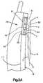
- the air bag 50is inflatable from its stored condition to an inflated condition (best illustrated in dashed lines in Fig. 2A).
- a cover panel 34(Fig. 4) is attached to an interior compartment panel 19 on the vehicle door 16 and covers the air bag 50 from view when the air bag 50 is in its stored condition.
- the air bag assembly 26also includes a diffuser 32 (Fig. 4) made of a flat plate 29 and a dished plate 31 connected to the flat plate 29.
- the dished plate 31has an annular projection 33 to which a neck area 35 of the air bag 50 is sealingly engaged.
- the flat plate 29 and the dished plate 31define a generally rectangular chamber 43 which communicates through an opening 45 in the projection 33 to the interior of the air bag 50.
- the flat plate 29 and the dished plate 31define an annular flange 39 which is fixed to the inner door panel 17 of the vehicle door 16 to fix the diffuser 32 to the inner door panel 17 of the vehicle door 16.
- the air bag assembly 26further includes an actuatable inflator 30 which actuates in response to receiving an ignition signal from the impact sensor 18 indicative of the occurrence of a side impact against the vehicle 10.
- a side impact against the vehicleoccurs when the vehicle experiences a substantial force or force component acting transverse to the forward and rearward directions of travel of the vehicle.
- the inflator 30contains a source of inflation fluid, preferably inert gas, such as a pyrotechnic gas generating material or a quantity of stored gas or a combination of stored gas and gas generating material.
- a source of inflation fluidpreferably inert gas, such as a pyrotechnic gas generating material or a quantity of stored gas or a combination of stored gas and gas generating material.
- the inflator 30directs gas to the chamber 43 of the diffuser 32.
- the gasis directed from chamber 43 through the opening 45 into the interior of the air bag 50 to inflate the air bag 50.
- the inflator 30is oriented so that the flow of gas from the inflator 30 is directed along the door 16 and causes the air bag 50 to inflate along the door 16 in the rearward direction of travel of the vehicle.
- the air bag compartment 36is confined so that the air bag 50 also breaks away the cover panel 34 and expands into the passenger compartment of the vehicle 10 as the air bag 50 inflates.
- the air bag 50When the air bag 50 expands to its inflated condition, it restrains movement of an occupant in the seat 12 and prevents the occupant from violently striking parts of the door 16. The air bag 50 then quickly collapses so that the occupant is free to exit from the vehicle.
- the air bag 50may be formed of a porous material and/or may have vents which enable the gas to flow out of the air bag 50 or may have some other structure to permit it to collapse.
- the air bag 50comprises three inflatable air bag portions 51, 52, 53 which are shown in their inflated conditions in dashed lines in Fig. 2A.
- the air bag portions 51, 52, 53are shown in their deflated conditions in solid lines in Figs. 1-4.
- Each of the air bag portions 51, 52, 53is tubular in shape and has its longitudinal central axis extending along the forward and rearward directions of travel of the vehicle.
- the air bag portions 51, 52, 53define chambers 61, 62, 63, respectively.
- the three chambers 61, 62, 63converge and communicate in the vicinity of the neck area 35 of the air bag 50.
- the chambers 61, 62, 63may be formed, for example, by sewing stitches at locations 55 and 56 on the air bag 50, as best shown in Fig. 3. Stitches at location 55 are sewn in the material of the air bag 50 to define in part the air bag portion 51 and the air bag portion 52. Stitches at location 56 are sewn in the material of the air bag 50 to define in part the air bag portion 52 and the air bag portion 53. The stitches 55, 56 terminate short of the end of the air bag 50 spaced from the diffuser 32. Thus, the three chambers 61, 62, 63 communicate at the end of the air bag spaced from the diffuser.
- the air bag 50may be constructed in a number of different ways. For example, a panel may be sewn into the air bag at the location of each of the stitches 55, 56. Such panels would give the air bag more extent into the passenger compartment.
- Each of the air bag portions 51, 52, 53is inflatable from a stored condition on the vehicle door 16 to an inflated condition between the door 16 and the occupant of the vehicle. More specifically, the air bag portion 51 is inflatable from a stored condition on the door 16 to an inflated condition between the door 16 and the shoulder area of the occupant. When inflated, the air bag portion 51 engages the shoulder area of the occupant. The inflated air bag portion 51 is located adjacent the shoulder area of the occupant to engage the shoulder area of the occupant to resist movement of the shoulder area of the occupant toward the door 16 when the occupant engages the inflated air bag portion 51.
- the air bag portion 52is inflatable from a stored condition on the vehicle door 16 to an inflated condition between the door 16 and the upper rib area of the occupant. When inflated, the air bag portion 52 engages the upper rib area of the occupant. The inflated air bag portion 52 is located adjacent the upper rib area of the occupant to engage the upper rib area of the occupant to resist movement of the upper rib area of the occupant toward the door 16 when the occupant engages the inflated air bag portion 52.
- the air bag portion 53is inflatable from a stored condition on the vehicle door 16 to an inflated condition between the door 16 and a rib area of the occupant lower than the rib area engaged by air bag portion 52. When inflated, the inflated air bag portion 53 engages the lower rib area of the occupant above the abdominal ribs so that the abdominal ribs are not significantly loaded. The inflated air bag portion 53 is located adjacent the lower rib area of the occupant to engage the lower rib area of the occupant to resist movement of the lower rib area of the occupant when the occupant engages the inflated air bag portion 53.
- the inflated air bag portion 51has an innermost occupant contact point X in the passenger compartment.
- the contact point Xlies in a first vertical plane R which extends in the forward and rearward directions of travel of the vehicle.
- the inflated air bag portion 52has an innermost occupant contact point Y in the passenger compartment which lies in a second vertical plane S extending in the forward and rearward directions of travel of the vehicle.
- the inflated air bag portion 53has an innermost occupant contact point Z in the passenger compartment which lies in a third vertical plane T extending in the forward and rearward directions of travel of the vehicle.
- a central vertical plane Pextends in the forward and rearward directions of travel of the vehicle and divides the vehicle in half in the forward and rearward directions of travel of the vehicle.
- the first, second, and third vertical planes R, S, Tlie parallel with the central vertical plane P.
- the first vertical plane Rlies closer in distance to the central vertical plane P than the second vertical plane S.
- the second vertical plane Slies closer in distance to the central vertical plane P than the third vertical plane T.
- the innermost occupant contact point Xlies closer to the central vertical plane P than the innermost occupant contact point Y which, in turn, lies closer in distance to the central vertical plane P than the innermost occupant contact point Z.
- contact point Xis closer to the central vertical plane P than contact points Y, Z, as the air bag portions 51, 52, 53 are inflating, the probability of the shoulder of the occupant engaging contact point X before the rib area of the occupant engages contact points Y, Z is higher than otherwise. It is known that the shoulder structure of a human can withstand higher loads and deflections than the upper rib area of a human. Also, the upper rib area can withstand higher loads than the lowest rib area of a human. Thus, the lowest rib area (abdominal ribs) is not significantly loaded by the illustrated system.
- the air bag 50restrains the vehicle occupant and has the advantage of minimizing the possibility of injury to the rib area of the occupant.
- the pressure in the chambers 61, 62, 63tends to equalize.
- the pressure in one region of the air bag 50may differ from the pressure in another region of the air bag 50.
- the pressure in the chamber 61could be higher than the pressure in the chambers 62, 63.
- the air bag portion 51could be restraining the occupant to a greater extent than the air bag portions 52, 53.
- FIG. 5A second embodiment of the present invention is illustrated in Fig. 5. Since the embodiment of the invention illustrated in Fig. 5 is generally similar to the embodiment illustrated in Figs. 1-4, similar numerals are utilized to designate similar components, the suffix letter "a" being associated with the numerals of the embodiment of Fig. 5 to avoid confusion.
- a vent valve 101is associated with the air bag portion 51a.
- a vent valve 102is associated with the air bag portion 52a.
- a vent valve 103is associated with the air bag portion 53a.
- the vent valve 101opens when the pressure in the chamber 61a of the air bag portion 51a reaches a first predetermined pressure.
- the vent valve 102opens when the pressure in the chamber 62a of the air bag portion 52a reaches a second predetermined pressure which is less than the first predetermined pressure.
- the vent valve 103opens when the pressure in the chamber 63a of the air bag portion 53a reaches a third predetermined pressure which is less than the first predetermined pressure in chamber 61a and further is less than the second predetermined pressure in chamber 62a.
- Each of the air bag chambers 62a, 63ahas a relatively lower pressure than the air bag chamber 61a and, thus, the air bag portions 52a, 53a may restrain the rib areas of the occupant they contact with relatively lower forces.
- different pressurescan be provided in the air bag chambers 61a, 62a, and 63a by providing each air bag portion with a vent, with each vent being of a different area.
- inflation fluidmay flow from each air bag portion at different flow rates.
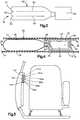
- FIG. 6 and 7A third embodiment of the present invention is illustrated in Figs. 6 and 7. Since the embodiment of the invention illustrated in Figs. 6 and 7 is generally similar to the embodiment illustrated in Figs. 1-4, similar numerals are utilized to designate similar components, the suffix letter "b" being associated with the numerals of the embodiment of Figs. 6 and 7 to avoid confusion.
- an air bag portion 210is inflatable into position to restrain the head of the occupant. When inflated, the air bag portion 210 extends across a B-pillar 240 of the vehicle as shown in Fig. 6.
- the air bag portion 210defines a chamber 212 which communicates through a plurality of passages 220 with the chamber 61b of the air bag portion 51b. Inflation fluid flows from the chamber 61b through the passages 220 into the chamber 212 when the air bag portion 51b is inflated and the torso of the occupant moves into the air bag portion 51b.
- the flow area of the passages 220controls the pressure in the chamber 61b. Also, a portion of the inflation fluid which flows into the chamber 212 may be inflation fluid vented from the chamber 61b. Suitable valves or blow-out patches (not shown) could be located in passages 220 which open at a predetermined pressure in the chamber 61b to then direct gas into the air bag portion 210 to inflate the air bag portion 210. Thus, the air bag portion 210 inflates into position to restrain the head of the occupant after the air bag portion 51b has been inflated. Typically, the air bag portion 210 is inflated about 10 to 20 milliseconds after the air bag 51b is inflated.
- the air bag portion 210When inflated, the air bag portion 210 protects the head of the occupant from striking an object intruding into the path of movement of the head, including the door window ledge and the B pillar 240 of the vehicle.
- the inflated air bag portion 210is located adjacent the head of the occupant to resist movement of the head of the occupant when the head of the occupant engages the inflated air bag portion 210.
- the torso of an occupantmay move laterally in the vehicle first and the head of the occupant may then rotate down toward the shoulder closest to the side of the vehicle which is impacted due to the torso movement.
- the air bag portion 210inflate after the air bag portion 51b has been inflated, the head of the occupant is restrained by the air bag portion 210 during its delayed movement relative to the torso down toward the shoulder.
- the head of the occupantis optimally protected against injury.
- FIG. 8A fourth embodiment of the present invention is illustrated in Fig. 8. Since the embodiment of the invention illustrated in Fig. 8 is generally similar to the embodiment illustrated in Figs. 6 and 7, similar numerals are utilized to designate similar components, the suffix letter "c" being associated with the numerals of the embodiment of Fig. 8 to avoid confusion.
- a vent valve 301is associated with the air bag portion 51c.
- a vent valve 302is associated with the air bag portion 52c.
- a vent valve 303is associated with the air bag portion 53c.
- the vent valve 301opens when the pressure in the chamber 61c of the air bag portion 51c reaches a first predetermined pressure.
- the vent valve 302opens when the pressure in the chamber 62c of the air bag portion 52c reaches a second predetermined pressure which is less than the first predetermined pressure.
- the vent valve 303opens when the pressure in the chamber 63c of the air bag portion 53c reaches a third predetermined pressure which is less than the second predetermined pressure in chamber 62c.
- the air bag chamber 61chas a greater pressure than the air bag chambers 62c, 63c and, thus, the air bag portion 51c can restrain the shoulder of the occupant with relatively high force.
- the air bag portions 52c, 53ccan apply a relatively low force against the rib areas of the occupant they engage since the pressures in the chambers 62c, 63c are both lower than the pressure in the chamber 61c.
- different pressurescan be provided in the air bag chambers 61c, 62c, 63c by providing each air bag portion with a vent of a different area.
- inflation fluid in the embodiment of Fig. 8is directed from the chamber 61c of the air bag portion 51c through the passages 220c to the chamber 212c of the air bag portion 210c after the air bag portion 51c has been inflated.
- the air bag portion 210cthereby protects the occupant's head due to head movement which occurs in a side impact against the vehicle after the torso moves.
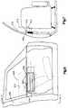
- FIG. 9A fifth embodiment of the present invention is illustrated in Figs. 9 and 10. Since the embodiment of the invention illustrated in Figs. 9 and 10 is generally similar to the embodiment illustrated in Figs. 1-4, similar numerals are utilized to designate similar components, the suffix letter "d" being associated with the numerals of the embodiment of Figs. 9 and 10 to avoid confusion.
- each of the air bag portions 51d, 52d, 53d of the air bag 50dhas an extra long length.
- the extra long length of the air bag portions 51d, 52d, 53dform an inflatable flap portion 400 which extends from the air bag portions 51d, 52d, 53d.
- the flap portion 400is folded over in a manner as best shown in Fig. 10. The flap portion 400 is folded over so that the air bag 50d including the flap portion 400 can fit into the air bag compartment 36d in the vehicle door 16d.
- the flap portion 400pivots from the compartment 36d and extends into the region adjoining the B-pillar area 440 (Fig. 9) of the vehicle. If the seat 12d is adjusted to a rearward position as shown in Fig. 9 and the flap portion 400 extends into the region adjoining the B-pillar area 440 upon a side impact against the vehicle, the occupant and the B-pillar area 440 are prevented from violently contacting each other.
- FIG. 11 and 12A sixth embodiment of the present invention is illustrated in Figs. 11 and 12. Since the embodiment of the invention illustrated in Figs. 11 and 12 is generally similar to the embodiment illustrated in Figs. 1-4, similar numerals are utilized to designate similar components, the suffix letter "e" being associated with the numerals of the embodiment of Figs. 11 and 12 to avoid confusion.
- the air bag portions 51e, 52e, 53emay be connected at locations 521, 522, 523, respectively to the cover panel 34e using, for example, a suitable adhesive material or the like.
- the cover panel 34emay define the passenger compartment of the vehicle.
- a first folded tether strap 500is connected between the inner door panel 17e and an upper end portion 510 of the cover panel 34e.
- a second folded tether strap 502is connected between the inner door panel 17e and the cover panel 34e at a lower end portion 512 of the cover panel 34e.
- the air bag portions 51e, 52e, 53eexpand into the vehicle occupant compartment to protect the occupant. Since the cover panel 34e is connected to the air bag portions 51e, 52e, 53e, the cover panel 34e also moves into the vehicle occupant compartment.
- the first and second tether straps 500, 502unfold as the air bag portions 51e, 52e, 53e expand and the cover panel 34e moves into the vehicle occupant compartment.
- the first and second tether straps 500, 502limit the travel of the air bag 50e and the cover panel 34e into the vehicle occupant compartment.
- first and second tether straps 500, 502hold the cover panel 34e from moving away from the air bag portions 51e, 52e, 53e as the air bag portions 51e, 52e, 53e are expanding and the cover panel 34e is moving into the vehicle occupant compartment.
- the cover panel 34eacts as a pad to cushion and may spread the contact forces acting between the air bag portions 51e, 52e, 53e and the occupant.
- the inflator 32eprovides inflation fluid flow in the rearward direction of travel of the vehicle, the portion of the pad 34e toward the front of the vehicle has a tendency to be pressurized faster than the portion of the pad 34e toward the rear of the vehicle. This difference in pressurization of the pad 34e would cause the force of deployment of the pad 34e acting against an out of position occupant, e.g. an occupant leaning forward and toward the vehicle door 16e, to be attenuated.
Landscapes
- Engineering & Computer Science (AREA)
- Mechanical Engineering (AREA)
- Air Bags (AREA)
Description
- The present invention relates to a method andapparatus for protecting an occupant of a vehicle upon acollision or the like, and is particularly directed to amethod and apparatus for restraining an occupant of avehicle upon a side impact against the vehicle.
- A vehicle occupant restraint for protecting anoccupant of a vehicle upon a side impact against thevehicle is known. Typically, such a vehicle occupantrestraint includes an inflatable air bag and a source ofinflation fluid for inflating the air bag, both of whichare mounted on a vehicle door. When a side impact againstthe vehicle occurs, the source of inflation fluid providesinflation fluid to inflate the air bag. The inflated airbag restrains movement of the occupant and prevents theoccupant from violently striking parts of the vehicleduring a side impact against the vehicle.
- A one-piece side impact air bag is known fromJP-A-51 62598. This document discloses an airbag having ahorizontal portion and a vertical portion.
- An alternative vehicle occupant restraint is disclosedin FR-A-2,675,098 corresponding to the preamble of
claims 1 and 4comprising a plurality of airbags. - DE-A-4,119,788 discloses a vehicle occupant restraintlocated on the side of a vehicle.
- DE-A-2,222,621 discloses an airbag comprising aplurality of compartments.
- In accordance with one aspect of the presentinvention, a vehicle occupant shoulder restraint means islocated on a vehicle side, such as on the vehicle door, andis inflatable from a stored condition to an inflatedcondition between the vehicle side and the shoulder area ofan occupant of the vehicle. When inflated, the vehicleoccupant shoulder restraint means engages the shoulder ofthe occupant. A vehicle occupant upper rib restraint meansseparate from the shoulder restraint means is also locatedon the vehicle side and is inflatable from a storedcondition to an inflated condition between the vehicle sideand the upper rib area of the occupant. When inflated, thevehicle occupant upper rib restraint means engages theupper rib area of the occupant.
- Sensor means is provided for sensing a side impactagainst the vehicle. Means is provided for directinginflation fluid into the vehicle occupant shoulderrestraint means and the vehicle occupant upper ribrestraint means when a side impact against the vehicle issensed by the sensor means.
- The occupant shoulder restraint means has an innermostoccupant contact point in the passenger compartment whichlies in a first vertical plane extending in the forward andrearward directions of travel of the vehicle when theoccupant shoulder restraint means is inflated. Theoccupant upper rib restraint means has an innermost occupant contact point in the passenger compartment whichlies in a second vertical plane extending in the forwardand rearward directions of travel of the vehicle when theoccupant upper rib restraint means is inflated. The firstand second vertical planes lie parallel with a centralvertical plane which extends in the forward and rearwarddirections of travel of the vehicle and divides the vehiclein half in the forward and rearward directions of travel ofthe vehicle. The first vertical plane lies closer indistance to the central vertical plane than the secondvertical plane. Thus, the innermost occupant contact pointof the occupant shoulder restraint means is closer to theoccupant than the innermost occupant contact point of theoccupant upper rib restraint means when the occupantshoulder restraint means and the occupant upper ribrestraint means are inflated.
- In accordance with a second aspect of the invention,an apparatus for use in a vehicle having a passengercompartment and a vehicle front, rear, and side, and acentral vertical plane extending in the forward andrearward directions of travel of the vehicle and dividingthe vehicle in half in said forward and rearward directionsof travel, comprises:
- vehicle occupant shoulder restraint means located onthe vehicle side and inflatable from a stored condition toan inflated condition between the vehicle side and theshoulder area of an occupant of the vehicle and for, when inflated, engaging the shoulder area of the occupant;
- vehicle occupant upper rib restraint means other thansaid shoulder restraint means located on the vehicle sideand inflatable from a stored condition to an inflatedcondition between the vehicle side and the upper rib areaof an occupant of the vehicle and for, when inflated,engaging the upper rib area of the occupant;
- sensor means for sensing a side impact against thevehicle, and
- means for directing inflation fluid into said vehicleoccupant shoulder restraint means and said vehicle occupantrib restraint means when a side impact against the vehicleis sensed by said sensor means;
and is characterised in that: - pad means are associated with said occupant shoulderrestraint means and said occupant upper rib restraint meansfor acting between said occupant shoulder restraint meansand said occupant upper rib restraint means and theoccupant, wherein at least one tether strap is provided forinterconnecting the vehicle side and said pad means and forlimiting movement of said pad means, said occupant shoulderrestraint means and said occupant rib restraint means intothe vehicle passenger compartment when said occupantshoulder restraint means and said occupant rib restraintmeans are inflated, said pad means in the region of saidoccupant shoulder restraint means having an innermostoccupant contact point in the passenger compartment whensaid occupant shoulder restraint means is inflated lying closer in distance to said central plane than an innermostoccupant contact point in the passenger compartment of saidpad means in the region of said occupant rib restraintmeans when said occupant rib restraint means is inflated.
- Since the innermost occupant contact point of theoccupant shoulder restraint means is closer to the occupantthan the innermost occupant contact point of the occupantupper rib restraint means, as the occupant shoulderrestraint means and the occupant upper rib restraint meansare inflating, the probability of the shoulder of theoccupant engaging the occupant shoulder restraint meansbefore the upper rib area of the occupant engages theoccupant upper rib restraint means is higher thanotherwise. Thus, the shoulder of the occupant is morelikely to be restrained by the inflating occupant shoulder restraint means before the upper rib area of the occupantis restrained by the inflating occupant upper rib restraintmeans.
- It is known that the shoulder structure of a human canwithstand higher loads and deflections than the upper ribarea of a human. Also, it is known that the upper rib areacan withstand higher loads and deflections than the lowestrib area (abdominal ribs) of a human. It is also knownthat the lowest rib area is more prone to injury than theupper rib area which, in turn, is more prone to injury thanthe shoulder structure of a human.
- By restraining the shoulder of the occupant beforerestraining the upper rib area of the occupant inaccordance with the present invention, the probability ofinjury to the upper rib area of the occupant is minimized.Moreover, the lowest rib area of the occupant is notsignificantly loaded by the present invention. Thus, inaccordance with the present invention, there is a highpotential for applying a larger amount of restraint to theshoulder of the occupant than to the upper rib area of theoccupant and a low potential for injury to the rib area ofthe occupant. The vehicle occupant restraint means may also include aninflatable portion for, when inflated, engaging the head ofthe occupant. Preferably, the time at which the head ofthe occupant is engaged is delayed relative to the time atwhich the shoulder of the occupant is engaged by theinflating occupant shoulder restraint means.
- An advantage results from restraining the head of anoccupant by an occupant restraint means later than when theshoulder of the occupant is restrained. Specifically,during a side impact against the vehicle, the torso maymove out from under the head, causing the head to rotatetoward the side of the vehicle which was impacted. Bydelaying the time at which the head of the occupant isengaged and restrained by a third portion of the vehicleoccupant restraint means relative to the time at which theshoulder of the occupant is engaged by a first portion ofthe vehicle occupant restraint means, the occupant isoptimally protected against injury to the head as well asthe torso.
- The foregoing and other features of the presentinvention will become apparent to one skilled in the art towhich the present invention relates upon consideration ofthe following description of the invention with referenceto the accompanying drawings, wherein:
- Fig. 1 is a schematic illustration of a vehicleembodying an inflatable vehicle occupant restraint systemconstructed in accordance with the present invention;
- Fig. 2 is a schematic view in the direction of line 2-2of Fig. 1;
- Fig. 2A is an enlarged view of portion of Fig. 2;
- Fig. 3 is an enlarged view of a portion of Fig. 2, asviewed in the direction of line 3-3 of Fig. 2;
- Fig. 4 is an enlarged sectional view of a portion ofFig. 1, as viewed in the direction of line 4-4 of Fig. 1;
- Fig. 5 is a view, similar to Fig. 2, showing a secondembodiment of the present invention;
- Fig. 6 is a view, similar to Fig. 1, showing a thirdembodiment of the present invention;
- Fig. 7 is a view in the direction of line 7-7 of Fig.6; and
- Fig. 8 is a view, similar to Fig. 7, showing a fourthembodiment of the present invention;
- Fig. 9 is a view, similar to Fig. 1, showing a fifthembodiment of the present invention;
- Fig. 10 is an enlarged schematic sectional view of aportion of Fig. 9, as viewed in the direction of line 10-10of Fig. 9;
- Fig. 11 is a schematic end view of an air bag assemblyshowing a sixth embodiment of the present invention; and
- Fig. 12 is a view similar to Fig. 11 but showing partsin different positions.
- The present invention is directed to an inflatablevehicle occupant restraint apparatus to restrain movementof an occupant of a vehicle upon a side impact against thevehicle. The specific construction of the occupantrestraint apparatus may vary. By way of example, aninflatable vehicle
occupant restraint apparatus 10 isillustrated in Fig. 1. The vehicleoccupant restraintapparatus 10 is in a vehicle which has a forward directionof travel indicated by an arrow A and a rearward directionof travel indicated by an arrow B. - Referring to Figs. 1 and 2, the vehicle includes a
vehicle seat 12 located in the passenger compartment of thevehicle and mounted on aseat track 14. Avehicle door 16is located on the side of the vehicle beside theseat 12.Thedoor 16 allows for ingress of an occupant to thepassenger compartment and egress of an occupant from thepassenger compartment. - An impact sensor 18 of any suitable known constructionis mounted on the
door 16, for example, or any other portion of the vehicle. When a side impact of at least apredetermined magnitude against the vehicle occurs, theimpact sensor 18 provides a signal indicative of theimpact. - An
air bag assembly 26 is mounted to aninner doorpanel 17 of thevehicle door 16. Theair bag assembly 26includes aninflatable air bag 50 which, when inflated,protects an occupant in theseat 12. As shown in Figs. 1-4,theair bag 50 is disposed in anair bag compartment 36in the side of the vehicle, and in particular, in thevehicle door 16, when theair bag 50 is in a storedcondition (illustrated in solid lines in Figs. 1 and 4).Theair bag 50 is inflatable from its stored condition toan inflated condition ( best illustrated in dashed lines inFig. 2A). A cover panel 34 (Fig. 4) is attached to aninterior compartment panel 19 on thevehicle door 16 andcovers theair bag 50 from view when theair bag 50 is inits stored condition. - The
air bag assembly 26 also includes a diffuser 32(Fig. 4) made of aflat plate 29 and a dishedplate 31connected to theflat plate 29. The dishedplate 31 has anannular projection 33 to which aneck area 35 of theairbag 50 is sealingly engaged. Theflat plate 29 and thedishedplate 31 define a generallyrectangular chamber 43which communicates through an opening 45 in theprojection 33 to the interior of theair bag 50. Theflat plate 29and the dishedplate 31 define anannular flange 39 which is fixed to theinner door panel 17 of thevehicle door 16to fix thediffuser 32 to theinner door panel 17 of thevehicle door 16. - The
air bag assembly 26 further includes anactuatableinflator 30 which actuates in response to receiving anignition signal from the impact sensor 18 indicative of theoccurrence of a side impact against thevehicle 10. A sideimpact against the vehicle occurs when the vehicleexperiences a substantial force or force component actingtransverse to the forward and rearward directions of travelof the vehicle. - The inflator 30 contains a source of inflation fluid,preferably inert gas, such as a pyrotechnic gas generatingmaterial or a quantity of stored gas or a combination ofstored gas and gas generating material. When actuated, the
inflator 30 directs gas to thechamber 43 of thediffuser 32. The gas is directed fromchamber 43 through theopening 45 into the interior of theair bag 50 to inflatetheair bag 50. The inflator 30 is oriented so that theflow of gas from the inflator 30 is directed along thedoor 16 and causes theair bag 50 to inflate along thedoor 16in the rearward direction of travel of the vehicle. Theair bag compartment 36 is confined so that theair bag 50also breaks away thecover panel 34 and expands into thepassenger compartment of thevehicle 10 as theair bag 50inflates. - When the
air bag 50 expands to its inflated condition,it restrains movement of an occupant in theseat 12 andprevents the occupant from violently striking parts of thedoor 16. Theair bag 50 then quickly collapses so that theoccupant is free to exit from the vehicle. To permit theair bag 50 to collapse, theair bag 50 may be formed of aporous material and/or may have vents which enable the gasto flow out of theair bag 50 or may have some otherstructure to permit it to collapse. - In accordance with the present invention, the
air bag 50 comprises three inflatableair bag portions air bag portions air bag portions air bag portions chambers chambers neck area 35 of theair bag 50. Thechambers locations air bag 50, as best shown in Fig. 3. Stitches atlocation 55 are sewn in the material of theair bag 50 todefine in part theair bag portion 51 and theair bagportion 52. Stitches atlocation 56 are sewn in thematerial of theair bag 50 to define in part theair bag portion 52 and theair bag portion 53. Thestitches air bag 50 spaced fromthediffuser 32. Thus, the threechambers - The
air bag 50 may be constructed in a number ofdifferent ways. For example, a panel may be sewn into theair bag at the location of each of thestitches - Each of the
air bag portions vehicle door 16 to aninflated condition between thedoor 16 and the occupant ofthe vehicle. More specifically, theair bag portion 51 isinflatable from a stored condition on thedoor 16 to aninflated condition between thedoor 16 and the shoulderarea of the occupant. When inflated, theair bag portion 51 engages the shoulder area of the occupant. The inflatedair bag portion 51 is located adjacent the shoulder area ofthe occupant to engage the shoulder area of the occupant toresist movement of the shoulder area of the occupant towardthedoor 16 when the occupant engages the inflatedair bagportion 51. - The
air bag portion 52 is inflatable from a storedcondition on thevehicle door 16 to an inflated conditionbetween thedoor 16 and the upper rib area of the occupant.When inflated, theair bag portion 52 engages the upper rib area of the occupant. The inflatedair bag portion 52 islocated adjacent the upper rib area of the occupant toengage the upper rib area of the occupant to resistmovement of the upper rib area of the occupant toward thedoor 16 when the occupant engages the inflatedair bagportion 52. - The
air bag portion 53 is inflatable from a storedcondition on thevehicle door 16 to an inflated conditionbetween thedoor 16 and a rib area of the occupant lowerthan the rib area engaged byair bag portion 52. Wheninflated, the inflatedair bag portion 53 engages the lowerrib area of the occupant above the abdominal ribs so thatthe abdominal ribs are not significantly loaded. Theinflatedair bag portion 53 is located adjacent the lowerrib area of the occupant to engage the lower rib area ofthe occupant to resist movement of the lower rib area ofthe occupant when the occupant engages the inflatedair bagportion 53. - Referring to Fig. 2, the inflated
air bag portion 51has an innermost occupant contact point X in the passengercompartment. The contact point X lies in a first verticalplane R which extends in the forward and rearwarddirections of travel of the vehicle. The inflatedair bagportion 52 has an innermost occupant contact point Y in thepassenger compartment which lies in a second vertical planeS extending in the forward and rearward directions oftravel of the vehicle. Similarly, the inflatedair bag portion 53 has an innermost occupant contact point Z in thepassenger compartment which lies in a third vertical planeT extending in the forward and rearward directions oftravel of the vehicle. - A central vertical plane P extends in the forward andrearward directions of travel of the vehicle and dividesthe vehicle in half in the forward and rearward directionsof travel of the vehicle. The first, second, and thirdvertical planes R, S, T lie parallel with the centralvertical plane P. The first vertical plane R lies closerin distance to the central vertical plane P than the secondvertical plane S. The second vertical plane S lies closerin distance to the central vertical plane P than the thirdvertical plane T. Thus, the innermost occupant contactpoint X lies closer to the central vertical plane P thanthe innermost occupant contact point Y which, in turn, liescloser in distance to the central vertical plane P than theinnermost occupant contact point Z.
- Since contact point X is closer to the centralvertical plane P than contact points Y, Z, as the
air bagportions air bag 50 first and is able to withstand moreforce than the upper and lower rib areas of the occupant,theair bag 50 restrains the vehicle occupant and has theadvantage of minimizing the possibility of injury to therib area of the occupant. - When the
air bag 50 is inflated, the pressure in thechambers air bag 50 may differ from the pressure in another region of theair bag 50. For example, at a given instant, the pressurein thechamber 61 could be higher than the pressure in thechambers air bag portion 51 could berestraining the occupant to a greater extent than theairbag portions - A second embodiment of the present invention isillustrated in Fig. 5. Since the embodiment of theinvention illustrated in Fig. 5 is generally similar to theembodiment illustrated in Figs. 1-4, similar numerals areutilized to designate similar components, the suffix letter"a" being associated with the numerals of the embodiment ofFig. 5 to avoid confusion.
- As shown in Fig. 5, a
vent valve 101 is associatedwith theair bag portion 51a. Avent valve 102 isassociated with theair bag portion 52a. Similarly, avent valve 103 is associated with theair bag portion 53a. Thevent valve 101 opens when the pressure in thechamber 61aof theair bag portion 51a reaches a first predeterminedpressure. Thevent valve 102 opens when the pressure inthechamber 62a of theair bag portion 52a reaches a secondpredetermined pressure which is less than the firstpredetermined pressure. Thevent valve 103 opens when thepressure in thechamber 63a of theair bag portion 53areaches a third predetermined pressure which is less thanthe first predetermined pressure inchamber 61a and furtheris less than the second predetermined pressure inchamber 62a. - When a vent valve opens, inflation fluid is releasedfrom the respective chamber to control the pressure in thatchamber. Since the
chamber 61a of theair bag portion 51ais vented at a pressure which is greater than the pressureat which thechamber 62a of theair bag portion 52a isvented and the pressure at which thechamber 63a of theairbag portion 53a is vented, theair bag chamber 61a has arelatively higher pressure thanair bag chambers air bag portion 51a may restrain theshoulder of the occupant with a relatively high force.Each of theair bag chambers air bag chamber 61a and, thus, theair bag portions air bag chambers - A third embodiment of the present invention isillustrated in Figs. 6 and 7. Since the embodiment of theinvention illustrated in Figs. 6 and 7 is generally similarto the embodiment illustrated in Figs. 1-4, similarnumerals are utilized to designate similar components, thesuffix letter "b" being associated with the numerals of theembodiment of Figs. 6 and 7 to avoid confusion.
- As shown in Figs. 6 and 7, an
air bag portion 210 isinflatable into position to restrain the head of theoccupant. When inflated, theair bag portion 210 extendsacross a B-pillar 240 of the vehicle as shown in Fig. 6.Theair bag portion 210 defines achamber 212 whichcommunicates through a plurality ofpassages 220 with thechamber 61b of theair bag portion 51b. Inflation fluidflows from thechamber 61b through thepassages 220 intothechamber 212 when theair bag portion 51b is inflatedand the torso of the occupant moves into theair bagportion 51b. - The flow area of the
passages 220 controls thepressure in thechamber 61b. Also, a portion of theinflation fluid which flows into thechamber 212 may beinflation fluid vented from thechamber 61b. Suitablevalves or blow-out patches (not shown) could be located inpassages 220 which open at a predetermined pressure in thechamber 61b to then direct gas into theair bag portion 210to inflate theair bag portion 210. Thus, theair bagportion 210 inflates into position to restrain the head ofthe occupant after theair bag portion 51b has beeninflated. Typically, theair bag portion 210 is inflatedabout 10 to 20 milliseconds after theair bag 51b isinflated. - When inflated, the
air bag portion 210 protects thehead of the occupant from striking an object intruding intothe path of movement of the head, including the door windowledge and theB pillar 240 of the vehicle. The inflatedair bag portion 210 is located adjacent the head of theoccupant to resist movement of the head of the occupantwhen the head of the occupant engages the inflatedair bagportion 210. - During a side impact against a vehicle, the torso ofan occupant may move laterally in the vehicle first and thehead of the occupant may then rotate down toward theshoulder closest to the side of the vehicle which isimpacted due to the torso movement. By having the
air bagportion 210 inflate after theair bag portion 51b has beeninflated, the head of the occupant is restrained by theairbag portion 210 during its delayed movement relative to thetorso down toward the shoulder. Thus, the head of theoccupant is optimally protected against injury. - A fourth embodiment of the present invention isillustrated in Fig. 8. Since the embodiment of theinvention illustrated in Fig. 8 is generally similar to theembodiment illustrated in Figs. 6 and 7, similar numeralsare utilized to designate similar components, the suffixletter "c" being associated with the numerals of theembodiment of Fig. 8 to avoid confusion.
- As shown in Fig. 8, a
vent valve 301 is associatedwith theair bag portion 51c. Avent valve 302 isassociated with theair bag portion 52c. Similarly, aventvalve 303 is associated with theair bag portion 53c. Thevent valve 301 opens when the pressure in thechamber 61cof theair bag portion 51c reaches a first predeterminedpressure. Thevent valve 302 opens when the pressure inthechamber 62c of theair bag portion 52c reaches a secondpredetermined pressure which is less than the firstpredetermined pressure. Thevent valve 303 opens when thepressure in thechamber 63c of theair bag portion 53creaches a third predetermined pressure which is less thanthe second predetermined pressure inchamber 62c. - When a vent valve opens, inflation fluid is releasedfrom the respective chamber to control the pressure in thatchamber. Since the
chamber 61c of theair bag portion 51cis vented at a pressure which is greater than the pressureat which thechamber 62c of theair bag portion 52c isvented and the pressure at which thechamber 63c of theairbag portion 53c is vented, theair bag chamber 61c has a greater pressure than theair bag chambers air bag portion 51c can restrain the shoulder ofthe occupant with relatively high force. Theair bagportions chambers chamber 61c. Alternatively, differentpressures can be provided in theair bag chambers - Like the third embodiment shown in Figs. 6 and 7 asalready described hereinabove, inflation fluid in theembodiment of Fig. 8 is directed from the
chamber 61c oftheair bag portion 51c through thepassages 220c to thechamber 212c of theair bag portion 210c after theair bagportion 51c has been inflated. Theair bag portion 210cthereby protects the occupant's head due to head movementwhich occurs in a side impact against the vehicle after thetorso moves. - A fifth embodiment of the present invention isillustrated in Figs. 9 and 10. Since the embodiment of theinvention illustrated in Figs. 9 and 10 is generallysimilar to the embodiment illustrated in Figs. 1-4, similarnumerals are utilized to designate similar components, thesuffix letter "d" being associated with the numerals of theembodiment of Figs. 9 and 10 to avoid confusion.
- As shown in Figs. 9 and 10, each of the
air bagportions air bag 50d has an extra longlength. The extra long length of theair bag portions inflatable flap portion 400 which extendsfrom theair bag portions air bag 50d is in its stored condition (illustrated in solid linesin Figs. 9 and 10), theflap portion 400 is folded over ina manner as best shown in Fig. 10. Theflap portion 400 isfolded over so that theair bag 50d including theflapportion 400 can fit into theair bag compartment 36d in thevehicle door 16d. - When the
air bag 50d is inflated (illustrated indashed lines in Fig. 9), theflap portion 400 pivots fromthecompartment 36d and extends into the region adjoiningthe B-pillar area 440 (Fig. 9) of the vehicle. If theseat 12d is adjusted to a rearward position as shown in Fig. 9and theflap portion 400 extends into the region adjoiningthe B-pillar area 440 upon a side impact against thevehicle, the occupant and the B-pillar area 440 areprevented from violently contacting each other. - A sixth embodiment of the present invention isillustrated in Figs. 11 and 12. Since the embodiment ofthe invention illustrated in Figs. 11 and 12 is generallysimilar to the embodiment illustrated in Figs. 1-4, similarnumerals are utilized to designate similar components, thesuffix letter "e" being associated with the numerals of theembodiment of Figs. 11 and 12 to avoid confusion.
- As shown in Fig. 11, the
air bag portions locations cover panel 34e using, for example, asuitable adhesive material or the like. Thecover panel 34e may define the passenger compartment of the vehicle. Afirst foldedtether strap 500 is connected between theinner door panel 17e and anupper end portion 510 of thecover panel 34e. A second foldedtether strap 502 isconnected between theinner door panel 17e and thecoverpanel 34e at alower end portion 512 of thecover panel 34e. - When the
air bag 50e is inflated from its storedcondition shown in Fig. 11 to an inflated condition shownin Fig. 12, theair bag portions cover panel 34e is connected to theair bagportions cover panel 34e also moves intothe vehicle occupant compartment. The first and secondtether straps 500, 502 unfold as theair bag portions cover panel 34e moves into thevehicle occupant compartment. The first and second tetherstraps 500, 502 limit the travel of theair bag 50e and thecover panel 34e into the vehicle occupant compartment.Also, the first and second tether straps 500, 502 hold thecover panel 34e from moving away from theair bag portions air bag portions cover panel 34e is moving into the vehicle occupant compartment. Thecover panel 34e acts asa pad to cushion and may spread the contact forces actingbetween theair bag portions inflator 32e provides inflationfluid flow in the rearward direction of travel of thevehicle, the portion of thepad 34e toward the front of thevehicle has a tendency to be pressurized faster than theportion of thepad 34e toward the rear of the vehicle.This difference in pressurization of thepad 34e wouldcause the force of deployment of thepad 34e acting againstan out of position occupant, e.g. an occupant leaningforward and toward the vehicle door 16e, to be attenuated. - From the above description of the invention, thoseskilled in the art will perceive improvements, changes andmodifications. Such improvements, changes andmodifications within the skill of the art are intended tobe covered by the appended claims.
Claims (8)
- An apparatus for use in a vehicle having apassenger compartment and a vehicle front, rear, and side,said apparatus comprising, vehicle occupant shoulderrestraint (51, 51a, 51b, 51c, 51d, 51e) means located onthe vehicle side and inflatable from a stored condition toan inflated condition between the vehicle side and theshoulder area of an occupant of the vehicle and for, wheninflated, engaging the shoulder area of the occupant,vehicle occupant upper rib restraint means (52, 52a, 52b,52c, 52d, 52e) other than said shoulder restraint meanslocated on the vehicle side and inflatable from a storedcondition to an inflated condition between the vehicle sideand the upper rib area of the occupant and for, wheninflated, engaging the upper rib area of the occupant,sensor means (18) for sensing a side impact against thevehicle, means (32) for directing inflation fluid into saidvehicle occupant shoulder restraint means and said vehicleoccupant rib restraint means when a side impact against thevehicle is sensed by said sensor means, characterized inthat said occupant shoulder restraint means has aninnermost occupant contact point (X) in the passengercompartment which lies in a first vertical plane (R)extending in the forward and rearward directions (A, B) oftravel of the vehicle when said occupant shoulder restraint means is inflated, and in that said occupant upper ribrestraint means has an innermost occupant contact point (Y)in the passenger compartment which lies in a secondvertical plane (S) extending in the forward and rearwarddirections of travel of the vehicle when said occupantupper rib restraint means is inflated, said first andsecond vertical planes (R, S) lying parallel with a centralvertical plane (P) which extends in the forward andrearward directions (A, B) of travel of the vehicle anddivides the vehicle in half in the forward and rearwarddirections (A, B) of travel of the vehicle, said firstvertical plane (R) lying closer in distance to said centralvertical plane (P) than said second vertical plane (S).
- An apparatus according to claim 1 characterizedin that an actuatable inflator (30) is provided for, whenactuated, releasing inflation fluid to be directed intosaid occupant shoulder restraint means (51, 51a, 51b, 51c,51d, 51e) and said occupant upper rib restraint means (52,52a, 52b, 52c, 52d, 52e), wherein (i) said occupantshoulder restraint means (51, 51a, 51b, 51c, 51d, 51e)includes a first inflatable portion defining a firstchamber (61, 61a, 61b, 61c, 61d, 61e) into which inflationfluid from said inflator flows to inflate said firstportion when a side impact against the vehicle occurs, and(ii) said occupant upper rib restraint (52, 52a, 52b, 52c,52d, 52e) includes a second inflatable portion defining a second chamber (62, 62a, 62b, 62c, 62d, 62e) into whichinflation fluid from said inflator flows to inflate saidsecond portion when a side impact against the vehicleoccurs.
- An apparatus according to claim 2 characterizedin that (i) said first portion of said occupant shoulderrestraint means (51, 51a, 51b, 51c, 51d, 51e) is locatedadjacent the shoulder area of the occupant to resistmovement of the shoulder area of the occupant when saidfirst portion is inflated and the shoulder area of theoccupant engages said first portion, and (ii) said secondportion of said occupant upper rib restraint means (52,52a, 52b, 52c, 52d, 52e) is located adjacent the upper ribarea of the occupant to resist movement of the rib area ofthe occupant when said second portion is inflated and theupper rib area of the occupant engages said second portion,and wherein each of said first and second portions of saidoccupant shoulder restraint means (51, 51a, 51b, 51c, 51d,51e) and said occupant upper restraint means (52, 52a, 52b,52c, 52d, 52e), when inflated, is tubular in shape and hasits longitudinal central axis extending along the forwardand rearward directions (A, B) of travel of the vehicle.
- An apparatus for use in a vehicle having a passengercompartment and a vehicle front, rear, and side, and acentral vertical plane (P) extending in the forward andrearward directions (A, B) of travel of the vehicle anddividing the vehicle in half in said forward and rearwarddirections (A, B) of travel, said apparatus comprising:vehicle occupant shoulder restraint means (51e) located onthe vehicle side and inflatable from a stored condition toan inflated condition between the vehicle side and theshoulder area of an occupant of the vehicle and for, wheninflated, engaging the shoulder area of the occupant,vehicle occupant upper rib restraint means (52e) other thansaid shoulder restraint means (51e) located on the vehicleside and inflatable from a stored condition to an inflatedcondition between the vehicle side and the upper rib areaof an occupant of the vehicle and for, when inflated,engaging the upper rib area of the occupant,sensor means (18) for sensing a side impact against thevehicle, andmeans (32) for directing inflation fluid into said vehicleoccupant shoulder restraint means (51e) and said vehicleoccupant rib restraint means (52e) when a side impactagainst the vehicle is sensed by said sensor means (18);
characterised in that:pad means (34e) are associated with said occupant shoulderrestraint means (51e) and said occupant upper rib restraintmeans (52e) for acting between said occupant shoulderrestraint means (51e) and said occupant upper rib restraintmeans (52e) and the occupant, wherein at least one tetherstrap (500, 502) is provided for interconnecting the vehicle side and said pad means (34e) and for limitingmovement of said pad means, said occupant shoulderrestraint means (51e) and said occupant rib restraintmeans (52e) into the vehicle passenger compartment whensaid occupant shoulder restraint means (51e) and saidoccupant rib restraint means (52e) are inflated, said padmeans (34e) in the region of said occupant shoulderrestraint means (51e) having an innermost occupant contactpoint in the passenger compartment when said occupantshoulder restraint means (51e) is inflated lying closer indistance to said central plane (P) than an innermostoccupant contact point in the passenger compartment of saidpad means (34e) in the region of said occupant ribrestraint means (52e) when said occupant rib restraintmeans (52e) is inflated. - An apparatus as claimed in claim 1 or claim 4characterised in that each of said first and secondportions includes vent valve means (101, 102, 301, 302) forreleasing inflation fluid from the chamber of therespective portion to control the pressure in the chamberof the respective portion.
- An apparatus as claimed in claim 5 characterised inthat (i) said vent valve means (101, 301) of said firstportion opens when the pressure in said first chamberreaches a first predetermined pressure, and (ii) said ventvalve means (102, 302) of said second portion opens whenthe pressure in said second chamber reaches a secondpredetermined pressure which is lower than said firstpredetermined pressure.
- An apparatus according to claim 1 or claim 2characterized in that vehicle occupant head restraint means(210, 210c) is located on the vehicle side and isinflatable from a stored condition on the vehicle side toan inflated condition between the vehicle side and the head of the occupant for, when inflated, engaging the head ofthe occupant.
- An apparatus according to claim 7 when dependent onclaim 2 characterized in that said occupant head restraintmeans (210, 210c) includes a third inflatable portiondefining a third chamber (212, 212c) into which inflationfluid from said first chamber (61, 61c) of said firstportion flows to inflate said third portion after saidfirst portion has been inflated, and in that said thirdportion of said occupant head restraint means (210, 210c)is located adjacent the head of the occupant to protect thehead of the occupant against forcibly striking an objectwhen said third portion is inflated.
Priority Applications (1)
| Application Number | Priority Date | Filing Date | Title |
|---|---|---|---|
| EP97200503AEP0775616A3 (en) | 1993-11-15 | 1994-11-01 | Method and apparatus for restraining an occupant of a vehicle upon a side impact against the vehicle |
Applications Claiming Priority (2)
| Application Number | Priority Date | Filing Date | Title |
|---|---|---|---|
| US08/153,074US5524924A (en) | 1993-11-15 | 1993-11-15 | Method and apparatus for restraining an occupant of a vehicle upon a side impact against the vehicle |
| US153074 | 1993-11-15 |
Related Child Applications (1)
| Application Number | Title | Priority Date | Filing Date |
|---|---|---|---|
| EP97200503ADivisionEP0775616A3 (en) | 1993-11-15 | 1994-11-01 | Method and apparatus for restraining an occupant of a vehicle upon a side impact against the vehicle |
Publications (3)
| Publication Number | Publication Date |
|---|---|
| EP0653335A2 EP0653335A2 (en) | 1995-05-17 |
| EP0653335A3 EP0653335A3 (en) | 1996-03-20 |
| EP0653335B1true EP0653335B1 (en) | 1999-06-23 |
Family
ID=22545668
Family Applications (2)
| Application Number | Title | Priority Date | Filing Date |
|---|---|---|---|
| EP94308039AExpired - LifetimeEP0653335B1 (en) | 1993-11-15 | 1994-11-01 | Apparatus for restraining an occupant of a vehicle upon a side impact against the vehicle |
| EP97200503AWithdrawnEP0775616A3 (en) | 1993-11-15 | 1994-11-01 | Method and apparatus for restraining an occupant of a vehicle upon a side impact against the vehicle |
Family Applications After (1)
| Application Number | Title | Priority Date | Filing Date |
|---|---|---|---|
| EP97200503AWithdrawnEP0775616A3 (en) | 1993-11-15 | 1994-11-01 | Method and apparatus for restraining an occupant of a vehicle upon a side impact against the vehicle |
Country Status (6)
| Country | Link |
|---|---|
| US (1) | US5524924A (en) |
| EP (2) | EP0653335B1 (en) |
| JP (1) | JP2780937B2 (en) |
| KR (1) | KR0147435B1 (en) |
| CA (1) | CA2134414C (en) |
| DE (1) | DE69419230T2 (en) |
Cited By (1)
| Publication number | Priority date | Publication date | Assignee | Title |
|---|---|---|---|---|
| US6851706B2 (en) | 2002-03-21 | 2005-02-08 | Autoliv Asp, Inc. | Side-impact, variable thickness vehicular airbag |
Families Citing this family (62)
| Publication number | Priority date | Publication date | Assignee | Title |
|---|---|---|---|---|
| US7338069B2 (en)* | 2004-04-02 | 2008-03-04 | Automotive Technologies International, Inc. | Airbags with internal valves |
| US20060202452A1 (en)* | 1994-05-23 | 2006-09-14 | Automotive Technologies International, Inc. | Side curtain and multi-compartment vehicular airbags |
| DE4434036A1 (en)* | 1994-09-23 | 1996-03-28 | Pars Passive Rueckhaltesysteme | Airbag module |
| US5570900A (en)* | 1995-05-23 | 1996-11-05 | Trw Vehicle Safety Systems Inc. | Side impact head air bag |
| US5566977A (en)* | 1995-06-01 | 1996-10-22 | Trw Vehicle Safety Systems Inc. | Air bag including restraint |
| US5586782A (en)* | 1995-06-26 | 1996-12-24 | Alliedsignal Inc. | Dual pressure side impact air bag |
| DE19529829C1 (en)* | 1995-08-14 | 1996-10-31 | Pars Passive Rueckhaltesysteme | Head and thorax protection air bag for vehicles |
| WO1997014586A1 (en)* | 1995-10-16 | 1997-04-24 | Breed Automotive Technology, Inc. | Side impact air bag |
| DE19538657A1 (en)* | 1995-10-17 | 1997-04-24 | Trw Repa Gmbh | Airbag side impact protection device |
| DE29517372U1 (en)* | 1995-11-02 | 1996-02-01 | Trw Repa Gmbh | Airbag side impact protection device |
| US7744122B2 (en)* | 1995-12-12 | 2010-06-29 | Automotive Technologies International, Inc. | Driver side aspirated airbags |
| US5718450A (en)* | 1996-01-19 | 1998-02-17 | Takata, Inc. | Inflatable restraint system having a head/thorax cushion for side impact protection |
| US5913536A (en)* | 1996-02-07 | 1999-06-22 | Trw Vehicle Safety System Inc. | Air bag module |
| JPH09323605A (en)* | 1996-03-27 | 1997-12-16 | Morton Internatl Inc | How to protect occupants in the passenger compartment of a car and how to fold an airbag cushion |
| JP3397041B2 (en)* | 1996-03-28 | 2003-04-14 | 豊田合成株式会社 | Side collision airbag |
| JP2894274B2 (en)* | 1996-04-08 | 1999-05-24 | 三菱自動車工業株式会社 | Airbag for side impact |
| JP2962225B2 (en)* | 1996-04-08 | 1999-10-12 | 三菱自動車工業株式会社 | Airbag for side impact |
| US5697641A (en)* | 1996-05-14 | 1997-12-16 | Trw Vehicle Safety Systems Inc. | Inflatable vehicle occupant protection device and method of inflating the device |
| US5647609A (en)* | 1996-08-16 | 1997-07-15 | General Motors Corporation | Inflatable restraint cushion |
| CA2265688A1 (en)* | 1996-09-21 | 1998-03-26 | Breed Automotive Technology, Inc. | Apparatus for protecting a vehicle occupant |
| JP3430835B2 (en)* | 1996-09-26 | 2003-07-28 | 三菱自動車工業株式会社 | Air bag device |
| DE29616904U1 (en) | 1996-09-27 | 1997-01-30 | Trw Repa Gmbh | Protection device for vehicle occupants |
| JP3147172B2 (en)* | 1996-11-07 | 2001-03-19 | トヨタ自動車株式会社 | Installation structure of vehicle occupant protection system |
| DE19652019A1 (en)* | 1996-12-13 | 1998-06-18 | Takata Europ Gmbh | Airbag for a side airbag |
| DE29710745U1 (en)* | 1997-06-19 | 1997-10-16 | Trw Repa Gmbh | Knee restraint for vehicles |
| US6042141A (en)* | 1997-08-26 | 2000-03-28 | General Motors Corporation | Side restraint assembly |
| US6457740B1 (en) | 1998-06-19 | 2002-10-01 | Trw Vehicle Safety Systems Inc. | Vehicle occupant safety apparatus |
| US6367836B1 (en) | 1998-08-05 | 2002-04-09 | Toyoda Gosei Co., Ltd. | Airbag for head protecting airbag system |
| JP3347071B2 (en)* | 1998-09-10 | 2002-11-20 | 日本電気株式会社 | Occupant detection system |
| DE29822159U1 (en)* | 1998-12-11 | 1999-05-12 | Trw Repa Gmbh | Airbag side impact protection device |
| US6234516B1 (en) | 1999-06-07 | 2001-05-22 | Trw Vehicle Safety System Inc. | Inflatable curtain |
| DE19930157B4 (en)* | 1999-06-30 | 2012-10-31 | TAKATA Aktiengesellschaft | Airbag for a motor vehicle |
| DE19937151B4 (en)* | 1999-08-06 | 2006-11-02 | Daimlerchrysler Ag | Active occupant restraint system with ring and / or stitch-shaped ignition bus cable |
| US6250667B1 (en)* | 2000-01-03 | 2001-06-26 | Trw Vehicle Safety Systems Inc. | Inflatable side curtain |
| US6431590B1 (en) | 2000-09-28 | 2002-08-13 | Trw Vehicle Safety Systems Inc. | Inflatable side curtain |
| US6851707B2 (en) | 2000-03-17 | 2005-02-08 | Trw Vehicle Safety Systems Inc. | Inflatable side curtain |
| US6471240B2 (en) | 2000-03-17 | 2002-10-29 | Trw Vehicle Safety Systems Inc. | Inflatable side curtain |
| US6527296B2 (en) | 2000-03-17 | 2003-03-04 | Trw Vehicle Safety Systems Inc. | Inflatable side curtain |
| US7828321B2 (en)* | 2000-09-28 | 2010-11-09 | Trw Vehicle Safety Systems, Inc. | Inflatable side curtain that moves occupant's head away from vehicle side structure |
| US6508486B1 (en)* | 2001-06-06 | 2003-01-21 | Delphi Technologies, Inc. | Door mounted side restraint |
| JP3822475B2 (en) | 2001-09-14 | 2006-09-20 | 三菱電機株式会社 | Power system management method and power system management system |
| US6991254B2 (en)* | 2001-10-02 | 2006-01-31 | Honda Giken Kogyo Kabushiki Kaisha | Airbag system |
| US6517104B1 (en)* | 2002-01-28 | 2003-02-11 | Ford Global Technologies, Inc. | Air bag for third row vehicle passengers |
| JP4618271B2 (en)* | 2002-03-11 | 2011-01-26 | 豊田合成株式会社 | Side airbag device |
| US20030168836A1 (en)* | 2002-03-11 | 2003-09-11 | Eiji Sato | Side airbag apparatus |
| DE10257249A1 (en)* | 2002-12-07 | 2004-07-08 | Dr.Ing.H.C. F. Porsche Ag | Safety device for occupants of a motor vehicle |
| US7384062B2 (en)* | 2004-01-28 | 2008-06-10 | Nihon Plast Co., Ltd. | Airbag system |
| US20060022439A1 (en)* | 2004-07-30 | 2006-02-02 | Trw Vehicle Safety Systems Inc. | Inflatable vehicle occupant protection device with differentially pressurized chambers |
| WO2006132990A1 (en)* | 2005-06-03 | 2006-12-14 | Abc Group, Inc. | Active bolster |
| DE102005050935B4 (en)* | 2005-10-21 | 2011-03-24 | Autoliv Development Ab | Side impact protection device |
| US7980589B2 (en)* | 2005-11-17 | 2011-07-19 | Salflex Polymers Ltd. | Inflatable bolster |
| DE202006010878U1 (en)* | 2006-07-11 | 2006-09-21 | Takata-Petri Ag | Airbag arrangement for vehicle occupant restraint system has chamber section that extends forward when airbag inflated to protect occupant including for forward occupant movements at angle by catching associated occupant body regions |
| US7690682B2 (en)* | 2008-06-27 | 2010-04-06 | Autoliv Asp, Inc. | Folding method for door mounted inflatable curtain |
| DE102009033181B3 (en)* | 2009-07-13 | 2010-12-30 | Autoliv Development Ab | Vehicle seat, side airbag device and safety device |
| US8459689B2 (en)* | 2009-12-24 | 2013-06-11 | Salflex Polymers Ltd. | Passenger side active knee bolster |
| WO2011137517A1 (en) | 2010-05-05 | 2011-11-10 | Salflex Polymers Ltd. | Injection molded inflatable active bolster |
| US8579325B2 (en) | 2010-11-09 | 2013-11-12 | Salflex Polymers Ltd. | Active bolster |
| KR101241159B1 (en)* | 2010-12-08 | 2013-03-13 | 현대자동차주식회사 | Integrated air bag device of automible |
| WO2012109122A1 (en) | 2011-02-07 | 2012-08-16 | Salflex Polymers Limited | Active bolster assembly |
| JP6428141B2 (en)* | 2014-10-17 | 2018-11-28 | 三菱自動車工業株式会社 | Side airbag device |
| US10501043B2 (en)* | 2018-02-19 | 2019-12-10 | Ford Global Technologies, Llc | Assembly and method using an inflatable device within a vehicle having a detachable door |
| US11173863B1 (en)* | 2020-10-12 | 2021-11-16 | Ford Global Technologies, Llc | Restraint system |
Family Cites Families (22)
| Publication number | Priority date | Publication date | Assignee | Title |
|---|---|---|---|---|
| US3582107A (en)* | 1968-04-01 | 1971-06-01 | Eaton Yale & Towne | Inflatable vehicle confinement |
| US3642303A (en)* | 1970-02-13 | 1972-02-15 | Gen Motors Corp | Vehicle occupant restraint system |
| US3802719A (en)* | 1971-01-18 | 1974-04-09 | Eaton Yale & Towne | Inflatable safety apparatus for vehicle occupant |
| US3731949A (en)* | 1971-05-12 | 1973-05-08 | Allied Chem | Flat bag made of tubular sections |
| US3733091A (en)* | 1971-05-12 | 1973-05-15 | Gec Detroit | Occupant restraint cushion |
| DE3741637C2 (en)* | 1987-12-09 | 1994-06-09 | Keiper Recaro Gmbh Co | Vehicle seat, in particular motor vehicle seat |
| GB2225660A (en)* | 1988-12-05 | 1990-06-06 | Autoliv Dev | A trigger circuit arrangement for a vehicle safety device, eg a crash bag |
| JP2987153B2 (en)* | 1989-03-24 | 1999-12-06 | マツダ株式会社 | Energy absorption structure on the side of the vehicle |
| US4966388A (en)* | 1989-05-25 | 1990-10-30 | Collision Safety Engineering Inc. | Inflatable structures for side impact crash protection |
| JP2963948B2 (en)* | 1990-06-13 | 1999-10-18 | マツダ株式会社 | Energy absorption device on the side of the vehicle |
| JP2889644B2 (en)* | 1990-03-24 | 1999-05-10 | マツダ株式会社 | Device for absorbing collision energy to the side of the vehicle body |
| JP3107383B2 (en)* | 1990-03-26 | 2000-11-06 | マツダ株式会社 | Energy absorption structure on the side of the vehicle |
| JP2895578B2 (en)* | 1990-06-13 | 1999-05-24 | マツダ株式会社 | Energy absorption device on the side of the vehicle |
| DE4210562A1 (en)* | 1991-04-15 | 1992-10-22 | Volkswagen Ag | PASSENGER PROTECTION DEVICE ON ONE SIDE OF A VEHICLE SEAT |
| DE4119788A1 (en)* | 1991-06-15 | 1992-07-23 | Daimler Benz Ag | SIDE IMPACT PROTECTION DEVICE |
| JPH0542002U (en)* | 1991-11-13 | 1993-06-08 | 株式会社東海理化電機製作所 | Air bag device |
| JPH0544713U (en)* | 1991-11-25 | 1993-06-15 | 株式会社東海理化電機製作所 | Air bag device |
| JPH05162598A (en)* | 1991-12-13 | 1993-06-29 | Toyota Motor Corp | Side air bag device |
| US5333899A (en)* | 1992-02-25 | 1994-08-02 | Volkswagen Ag | Side airbag safety arrangement for vehicle occupants |
| DE4307175C2 (en)* | 1992-03-18 | 2002-02-28 | Volkswagen Ag | Passenger side protection for a motor vehicle |
| US5324072A (en)* | 1992-09-23 | 1994-06-28 | Morton International, Inc. | Side impact air bag |
| JPH06227348A (en)* | 1993-02-05 | 1994-08-16 | Toyota Motor Corp | Side airbag device |
- 1993
- 1993-11-15USUS08/153,074patent/US5524924A/ennot_activeExpired - Lifetime
- 1994
- 1994-10-26CACA002134414Apatent/CA2134414C/ennot_activeExpired - Fee Related
- 1994-11-01EPEP94308039Apatent/EP0653335B1/ennot_activeExpired - Lifetime
- 1994-11-01EPEP97200503Apatent/EP0775616A3/ennot_activeWithdrawn
- 1994-11-01DEDE69419230Tpatent/DE69419230T2/ennot_activeExpired - Fee Related
- 1994-11-04KRKR1019940028846Apatent/KR0147435B1/ennot_activeExpired - Fee Related
- 1994-11-15JPJP6280870Apatent/JP2780937B2/ennot_activeExpired - Lifetime
Cited By (1)
| Publication number | Priority date | Publication date | Assignee | Title |
|---|---|---|---|---|
| US6851706B2 (en) | 2002-03-21 | 2005-02-08 | Autoliv Asp, Inc. | Side-impact, variable thickness vehicular airbag |
Also Published As
| Publication number | Publication date |
|---|---|
| DE69419230T2 (en) | 2000-01-27 |
| EP0653335A3 (en) | 1996-03-20 |
| KR0147435B1 (en) | 1998-11-02 |
| EP0775616A2 (en) | 1997-05-28 |
| JP2780937B2 (en) | 1998-07-30 |
| KR950013844A (en) | 1995-06-15 |
| CA2134414C (en) | 1998-04-14 |
| DE69419230D1 (en) | 1999-07-29 |
| JPH07164996A (en) | 1995-06-27 |
| CA2134414A1 (en) | 1995-05-16 |
| EP0653335A2 (en) | 1995-05-17 |
| US5524924A (en) | 1996-06-11 |
| EP0775616A3 (en) | 1998-06-03 |
Similar Documents
| Publication | Publication Date | Title |
|---|---|---|
| EP0653335B1 (en) | Apparatus for restraining an occupant of a vehicle upon a side impact against the vehicle | |
| US11305720B2 (en) | Self-conforming rearseat air bag | |
| US10336282B2 (en) | Self-conforming rearseat air bag | |
| US7347444B2 (en) | Inflatable airbag with overlapping chamber | |
| US5913536A (en) | Air bag module | |
| US10730472B2 (en) | Airbag and method for protecting an occupant of a vehicle | |
| US6176515B1 (en) | Inflatable curtain with positioning device | |
| US5224732A (en) | Inflatable restraint system for side impact crash protection | |
| US6260877B1 (en) | Soft shell air bag | |
| WO2019168580A1 (en) | Roof-mounted occupant restraint system | |
| US20050029781A1 (en) | Dual cushion passenger airbag | |
| EP3470273B1 (en) | Self-conforming rearseat air bag | |
| EP2617607B1 (en) | Airbag arrangement | |
| US11628791B2 (en) | Driver airbag | |
| US5895069A (en) | Knee restraint means | |
| CN114763120A (en) | Occupant restraint system | |
| EP1452406A1 (en) | Child seat | |
| US11752970B1 (en) | One-way multiple chambers and cushions airbag | |
| US11498513B2 (en) | Airbag with passive and active vents | |
| US11724663B2 (en) | Air bag for oblique crash protection | |
| GB2317370A (en) | Two chamber airbag | |
| US11772595B2 (en) | Airbag with reinforced tether |
Legal Events
| Date | Code | Title | Description |
|---|---|---|---|
| PUAI | Public reference made under article 153(3) epc to a published international application that has entered the european phase | Free format text:ORIGINAL CODE: 0009012 | |
| AK | Designated contracting states | Kind code of ref document:A2 Designated state(s):BE DE ES FR GB IT NL SE | |
| PUAL | Search report despatched | Free format text:ORIGINAL CODE: 0009013 | |
| AK | Designated contracting states | Kind code of ref document:A3 Designated state(s):BE DE ES FR GB IT NL SE | |
| 17P | Request for examination filed | Effective date:19960304 | |
| 17Q | First examination report despatched | Effective date:19961106 | |
| GRAG | Despatch of communication of intention to grant | Free format text:ORIGINAL CODE: EPIDOS AGRA | |
| GRAG | Despatch of communication of intention to grant | Free format text:ORIGINAL CODE: EPIDOS AGRA | |
| GRAH | Despatch of communication of intention to grant a patent | Free format text:ORIGINAL CODE: EPIDOS IGRA | |
| GRAH | Despatch of communication of intention to grant a patent | Free format text:ORIGINAL CODE: EPIDOS IGRA | |
| GRAA | (expected) grant | Free format text:ORIGINAL CODE: 0009210 | |
| DX | Miscellaneous (deleted) | ||
| AK | Designated contracting states | Kind code of ref document:B1 Designated state(s):BE DE ES FR GB IT NL SE | |
| PG25 | Lapsed in a contracting state [announced via postgrant information from national office to epo] | Ref country code:SE Free format text:THE PATENT HAS BEEN ANNULLED BY A DECISION OF A NATIONAL AUTHORITY Effective date:19990623 Ref country code:NL Free format text:LAPSE BECAUSE OF FAILURE TO SUBMIT A TRANSLATION OF THE DESCRIPTION OR TO PAY THE FEE WITHIN THE PRESCRIBED TIME-LIMIT Effective date:19990623 Ref country code:ES Free format text:THE PATENT HAS BEEN ANNULLED BY A DECISION OF A NATIONAL AUTHORITY Effective date:19990623 Ref country code:BE Free format text:LAPSE BECAUSE OF FAILURE TO SUBMIT A TRANSLATION OF THE DESCRIPTION OR TO PAY THE FEE WITHIN THE PRESCRIBED TIME-LIMIT Effective date:19990623 | |
| REF | Corresponds to: | Ref document number:69419230 Country of ref document:DE Date of ref document:19990729 | |
| ET | Fr: translation filed | ||
| NLV1 | Nl: lapsed or annulled due to failure to fulfill the requirements of art. 29p and 29m of the patents act | ||
| PLBE | No opposition filed within time limit | Free format text:ORIGINAL CODE: 0009261 | |
| STAA | Information on the status of an ep patent application or granted ep patent | Free format text:STATUS: NO OPPOSITION FILED WITHIN TIME LIMIT | |
| 26N | No opposition filed | ||
| PGFP | Annual fee paid to national office [announced via postgrant information from national office to epo] | Ref country code:GB Payment date:20001004 Year of fee payment:7 | |
| PGFP | Annual fee paid to national office [announced via postgrant information from national office to epo] | Ref country code:FR Payment date:20001107 Year of fee payment:7 | |
| PG25 | Lapsed in a contracting state [announced via postgrant information from national office to epo] | Ref country code:GB Free format text:LAPSE BECAUSE OF NON-PAYMENT OF DUE FEES Effective date:20011101 | |
| REG | Reference to a national code | Ref country code:GB Ref legal event code:IF02 | |
| GBPC | Gb: european patent ceased through non-payment of renewal fee | Effective date:20011101 | |
| PG25 | Lapsed in a contracting state [announced via postgrant information from national office to epo] | Ref country code:FR Free format text:LAPSE BECAUSE OF NON-PAYMENT OF DUE FEES Effective date:20020730 | |
| REG | Reference to a national code | Ref country code:FR Ref legal event code:ST | |
| REG | Reference to a national code | Ref country code:FR Ref legal event code:ST | |
| PG25 | Lapsed in a contracting state [announced via postgrant information from national office to epo] | Ref country code:IT Free format text:LAPSE BECAUSE OF NON-PAYMENT OF DUE FEES Effective date:20051101 | |
| PGFP | Annual fee paid to national office [announced via postgrant information from national office to epo] | Ref country code:DE Payment date:20081128 Year of fee payment:15 | |
| PG25 | Lapsed in a contracting state [announced via postgrant information from national office to epo] | Ref country code:DE Free format text:LAPSE BECAUSE OF NON-PAYMENT OF DUE FEES Effective date:20100601 |