EP0653192B1 - High frequence surgical device to cut and/or coagulate biological tissues - Google Patents
High frequence surgical device to cut and/or coagulate biological tissuesDownload PDFInfo
- Publication number
- EP0653192B1 EP0653192B1EP95100278AEP95100278AEP0653192B1EP 0653192 B1EP0653192 B1EP 0653192B1EP 95100278 AEP95100278 AEP 95100278AEP 95100278 AEP95100278 AEP 95100278AEP 0653192 B1EP0653192 B1EP 0653192B1
- Authority
- EP
- European Patent Office
- Prior art keywords
- signal
- frequency
- surgical device
- voltage
- output voltage
- Prior art date
- Legal status (The legal status is an assumption and is not a legal conclusion. Google has not performed a legal analysis and makes no representation as to the accuracy of the status listed.)
- Expired - Lifetime
Links
- 230000003287optical effectEffects0.000claimsdescription3
- 238000002955isolationMethods0.000claims1
- 238000005345coagulationMethods0.000description45
- 230000015271coagulationEffects0.000description45
- 238000005520cutting processMethods0.000description43
- 238000000034methodMethods0.000description19
- 230000008569processEffects0.000description19
- 210000001519tissueAnatomy0.000description19
- 230000001112coagulating effectEffects0.000description9
- 238000010586diagramMethods0.000description7
- 230000001105regulatory effectEffects0.000description6
- 230000000694effectsEffects0.000description4
- 230000008901benefitEffects0.000description3
- 239000003990capacitorSubstances0.000description3
- 230000001419dependent effectEffects0.000description3
- 230000004913activationEffects0.000description2
- 238000010891electric arcMethods0.000description2
- 238000010292electrical insulationMethods0.000description2
- 238000001839endoscopyMethods0.000description2
- 230000007794irritationEffects0.000description2
- 210000003205muscleAnatomy0.000description2
- 210000005036nerveAnatomy0.000description2
- 230000007935neutral effectEffects0.000description2
- 238000001356surgical procedureMethods0.000description2
- 230000003213activating effectEffects0.000description1
- 230000008859changeEffects0.000description1
- 238000011161developmentMethods0.000description1
- 230000018109developmental processEffects0.000description1
- 230000005684electric fieldEffects0.000description1
- 239000004744fabricSubstances0.000description1
- 238000012544monitoring processMethods0.000description1
- 230000000704physical effectEffects0.000description1
- 238000005293physical lawMethods0.000description1
- 230000004044responseEffects0.000description1
- 230000000630rising effectEffects0.000description1
- 239000004065semiconductorSubstances0.000description1
- 230000001052transient effectEffects0.000description1
Images

Classifications
- A—HUMAN NECESSITIES
- A61—MEDICAL OR VETERINARY SCIENCE; HYGIENE
- A61B—DIAGNOSIS; SURGERY; IDENTIFICATION
- A61B18/00—Surgical instruments, devices or methods for transferring non-mechanical forms of energy to or from the body
- A61B18/04—Surgical instruments, devices or methods for transferring non-mechanical forms of energy to or from the body by heating
- A61B18/12—Surgical instruments, devices or methods for transferring non-mechanical forms of energy to or from the body by heating by passing a current through the tissue to be heated, e.g. high-frequency current
- A61B18/1206—Generators therefor
- A—HUMAN NECESSITIES
- A61—MEDICAL OR VETERINARY SCIENCE; HYGIENE
- A61B—DIAGNOSIS; SURGERY; IDENTIFICATION
- A61B18/00—Surgical instruments, devices or methods for transferring non-mechanical forms of energy to or from the body
- A61B2018/00636—Sensing and controlling the application of energy
- A61B2018/00773—Sensed parameters
- A61B2018/00892—Voltage
- H—ELECTRICITY
- H01—ELECTRIC ELEMENTS
- H01F—MAGNETS; INDUCTANCES; TRANSFORMERS; SELECTION OF MATERIALS FOR THEIR MAGNETIC PROPERTIES
- H01F19/00—Fixed transformers or mutual inductances of the signal type
- H01F19/04—Transformers or mutual inductances suitable for handling frequencies considerably beyond the audio range
- H01F19/08—Transformers having magnetic bias, e.g. for handling pulses
- H01F2019/085—Transformer for galvanic isolation
- Y—GENERAL TAGGING OF NEW TECHNOLOGICAL DEVELOPMENTS; GENERAL TAGGING OF CROSS-SECTIONAL TECHNOLOGIES SPANNING OVER SEVERAL SECTIONS OF THE IPC; TECHNICAL SUBJECTS COVERED BY FORMER USPC CROSS-REFERENCE ART COLLECTIONS [XRACs] AND DIGESTS
- Y10—TECHNICAL SUBJECTS COVERED BY FORMER USPC
- Y10S—TECHNICAL SUBJECTS COVERED BY FORMER USPC CROSS-REFERENCE ART COLLECTIONS [XRACs] AND DIGESTS
- Y10S128/00—Surgery
- Y10S128/908—Patient protection from electric shock
Definitions
- the inventionrelates to a High frequency surgical device for cutting and / or coagulating biological tissue using high-frequency electrical Current according to the preamble of claim 1.
- High-frequency surgical devices for cutting and / or coagulating biological tissue by means of high-frequency electrical alternating currenthave been known for over 50 years and have been used to equip surgical workplaces for many years surgical departments.
- high-frequency generatorswhich are the high-frequency ones required for cutting and / or coagulating generate electrical alternating currents.
- the frequency of the alternating currentshould be at least 300 kHz.
- the Nominal output power of high-frequency surgical devicesaveraged over one second, Do not exceed 400 watts.
- High-frequency surgical devicesare equipped with setting elements for the output power.
- high-frequency surgical devicesbe equipped with setting elements with which the output power to not more than 5% of the nominal output power or can be reduced to 10 watts, whichever is smaller.
- a filterwhich is at least one frequency of that of the electric arc generated non-harmonic frequencies of the fundamental frequency of the high-frequency oscillator from the electrical voltage or from the passes electrical current in the output. It can take turns Setpoint generator for the intensity of the cutting power or a setpoint generator switched on for the intensity of the coagulation power become. Furthermore, the output power of the power amplifier is determined by the output signal of the control amplifier by means of an amplitude modulator controlled so that the intensity of the arc to the set point of the setpoint generator concerned is regulated (EP-A-219 568).
- the diagrams abovehelp the surgeon at best when making a selection a high-frequency surgical device suitable for its special application. During use, especially when using the same high-frequency surgical equipment used for various operations, these diagrams help the surgeon Not.
- the power required during cutting and / or coagulationis not constant, as is often wrongly assumed, but by many various parameters, such as depth and speed of the cut, Size of the effective contact area between the coagulation electrode and tissue, Temperature of the coagulating tissue and physical properties of the tissue cutting and / or coagulating tissue, depending. In practice, neither the power required for the respective cutting and / or coagulation process still each of the high-frequency surgical device at any time of the cutting and / or Coagulation process delivered performance constant. This fact complicates the use of high-frequency surgery in that the reproducibility of the Cutting and / or coagulation effects to achieve constant quality of these effects is very difficult.
- the detectorwhich is the actual value of the output voltage to determine, consists of a coil 132 which is connected to the magnetic Circuit 34 of the resonant circuit of the oscillator is coupled.
- a Proportionality between the output voltage of the generator at the output sockets 122 and the output signal of this detectoris only so far insufficient than the voltage drop across that in high-frequency surgical devices common capacitor 118 in the application circuit, what low-frequency currents and the possible irritation of nerves and muscles and which should prevent according to the international Standard IEC 601 Part 2-2 must not be greater than 5000 pF, not is taken into account.
- Such a capacitorhas, for example 500 kHz 63.7 ohms and at 300 Hz for example 106 ohms resistance.
- the parameters listed abovewhich are those for cutting and / or Coagulation processes affect required performance as much as possible are automatically taken into account, so the quality of the cuts as well as the coagulation becomes independent of these parameters.
- the high frequency surgical equipment with display devicesequip the surgeon before and during cutting and / or Coagulate reliably relevant, determined by the high-frequency surgical device Show parameters that match the quality of the cut and / or the Correlate coagulation.
- the high-frequency surgical devicesare to be made possible to be equipped with safety devices which compliance with the relevant for cutting and / or coagulation processes Monitor parameters and deviations from setpoints of these parameters signal.
- the inventionis based on the knowledge that for cutting and / or coagulating biological tissue by means of high-frequency electrical alternating current required, the necessary for this, from cut to cut, from coagulation to coagulation and more or less during each cutting and / or coagulation process however, fluctuating performance with conventional high-frequency surgical devices neither optimally preset nor during individual cutting and / or coagulation processes optimally in accordance with the existing power requirement at any time can be delivered.
- the inventionis also based on the knowledge that a minimum voltage of approximately 150 V rms is required for cutting biological tissue by means of high-frequency electrical alternating current in order to achieve the electrical field strength required to ignite and maintain electrical arcs between the cutting electrode and tissue. It is also important in this context to observe that even small increases in the output voltage above the minimum voltage significantly change the cut quality, in such a way that the intensity of the electric arcs becomes significantly greater and thus the degree of coagulation of the cut surfaces during cutting. It is particularly important in this context to observe that the cutting quality becomes largely independent of the cutting speed and depth of the cut if the output voltage is kept constant.
- the solution to the above problemdiffers from that Known solution cited above in that the output voltage directly to the Output sockets are automatically checked and automatically connected to a setpoint device adjustable level is regulated. Control and automatic would be even better Regulation of the electrical voltage directly between the active electrode and the neutral electrode or even the biological tissue near the cutting and / or Coagulation processes or directly on the poles of bipolar electrodes.
- the inventionparticularly takes into account the problem of definitive voltage regulation is only possible if the shape of the voltage or its proportion is more harmonious and / or non-harmonic frequencies during all relevant operating conditions remains constant, otherwise the ratio of peak value to effective value or the RMS value would not be constant at any mean value of the voltage.
- the high-frequency surgical device according to the inventioncan therefore be further improved by equipping it with a high frequency generator that is one of constant voltage form independent of all relevant operating conditions, preferably a pure sinusoidal shape.
- the high-frequency surgical devicenot only offers the advantage of being reproducible and constant quality of cutting and / or coagulation processes, but also the advantage that the output voltage before and during Cutting and / or coagulation processes automatically controlled and on an electronic Display device can be displayed. So the actual value of the output voltage with the arbitrarily modulated in amplitude Setpoint of the output voltage are automatically compared and generates optical and / or acoustic signals at any selectable tolerance limits as soon as the selected tolerance limits are exceeded. An over or Falling below any selectable tolerance limits for the deviation of the actual value from the setpoint the output voltage can also be used to automatically switch off the high-frequency generator be used.
- the display of the actual value and / or the setpoint the output voltageallows both a pre-setting of the output voltage the use of the device for cutting and / or coagulating as well as a control the output voltage during cutting and / or coagulation processes.
- high-frequency surgical devicescan be used can be equipped with several setpoint devices that deliver different setpoints.
- different cutting and / or coagulation qualitiescan be pre-programmed and depending on the need via different buttons on the electrode handle, different Pedals or, for example, using buttons on the front panel of the high-frequency surgical device be retrieved.
- this designoffer integrated Semiconductor circuits and microprocessors easily realizable possibilities.
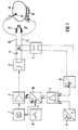
- Figure 1shows, shown as a block diagram, the most important components of a high-frequency surgical device.
- the output voltage at the output sockets 10, 11is not purely sinusoidal, but contains a non-negligible proportion of harmonic and / or nonharmonic frequencies of the fundamental frequency and / or the output voltage U a is modulated in amplitude and these deviations from the pure sinusoidal form are also not constant, but depending on the operating conditions, it must be checked whether the electrical signal a should be proportional to the peak value, the effective value or a mean value of the output voltage U a .
- the isolating transformer 5is required in order to ensure a sufficient electrical insulation gap between the application circuit 17 and the internal operating voltages of the high-frequency surgical device on the one hand and earth potential on the other hand.
- This required electrical insulationcan, however, also be realized with other components, such as by means of optocouplers, for example, a light bulb being connected to the output voltage U a and the light of which is supplied, for example, to a photo element, a photo transistor or a photo resistor, so that brightness fluctuations in the light bulb lead to proportional electrical signals at the photo element, photo transistor or photo resistor due to fluctuations in the output voltage U a .
- a voltage converterwould deliver an electrical signal proportional to the effective value of U a .
- the setpoint generator 8is designed in such a way that it either supplies a signal b modulated in amplitude over time. Depending on how large or small the control time constant of the entire control loop is, the output voltage U a follows the setpoint signal b more or less proportionally.
- FIG. 1also shows an oscillator 1, which is activated by means of a button or pedal 9, and schematically biological tissue 14, as well as an active 13 and a neutral electrode 15 and, alternatively, a bipolar electrode 12.
- the signal af (U a ) should be proportional to the effective value of the output voltage U a be.
- a photoelectric voltage converteras already described above, is suitable for this.
- the dependence of the proportionality of the electrical signal a on the shape of the output voltage U acan be avoided by using a high-frequency generator which supplies a sinusoidal output voltage U a to the output sockets 10, 11 under all relevant operating conditions, that is to say is free from harmonic and / or non-harmonic frequencies of the fundamental frequency.
- An advantageous embodiment of the high-frequency surgical deviceis therefore the combination with a high-frequency generator which, if possible, only generates the fundamental frequency, that is to say as far as possible no harmonic and / or non-harmonic frequencies of the fundamental frequency.
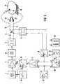
- An embodiment of a high-frequency surgical device, which is equipped with a high-frequency generator that supplies a pure, sinusoidal output voltage U ais shown in the form of a block diagram in FIG.
- the output of the high-frequency generatorconsisting of an oscillator 1, an amplifier 2 and an output transformer 3, is routed via a low-pass filter 18, so that only the fundamental frequency of the oscillator 1 is present at the output sockets 10, 11 .
- the automatic regulation of the output voltage U aoffers the advantage over known high-frequency surgical devices in which the output voltage is either insufficiently or not automatically regulated that the output voltage U a is automatically monitored in a simple manner and displayed on an electronic display device can. Since the level of the output voltage U a is an important parameter for coagulation and / or cutting processes, it is not only advantageous to regulate this constantly during coagulation and / or cutting processes, but it is reproducible even before the coagulation and / or cutting processes begin and to be able to adjust them sufficiently precisely.
- positive and / or negative deviationscan be signaled, the maximum permissible positive and / or negative deviations being able to be determined independently of one another and either triggering only the positive or the negative deviations or both optical 20 and / or acoustic 21 signals.
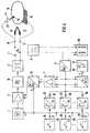
- FIG. 3Another advantageous embodiment of the high-frequency surgical device shown schematically in FIG. 3 offers the equipment with several, independent from each other adjustable setpoints 22, 23 ..., each setpoint using separate buttons 24.25 ... of an electrode handle or via separate pedals 24.25 ... can be activated.
- the individual setpoint devicescan also be operated using buttons on the front panel of the High-frequency surgical device selected and a finger button on the electrode handle or a pedal can be activated.
- FIG. 4schematically shows a further embodiment of the exemplary embodiment described with reference to FIG. 3 in the form of a block diagram.
- This exemplary embodiment shown in FIG. 4is equipped with a plurality of setpoint transmitters 22, 23 ... n which can be set independently of one another and which are each activated via separate buttons on the electrode handle and / or pedals 24, 25 ... n. 1 to 3, the setpoint generator may continuously supply a setpoint signal b, in the case of several setpoint generators according to FIG. 4, care must be taken to ensure that the respectively selected setpoint b1 or b2 etc. is only sent to the control amplifier 7 it is delivered how the respective setpoint device 22, 23 ... n is activated by means of buttons or pedal 24, 25 ... n.
- the various setpoint transmitterscan also be selected, for example, using buttons on the front plate of the high-frequency surgical device and activated using only one button 30 on the electrode handle 27 or by pedal.
- the outputs of the individual setpoint transmittersare decoupled from one another via diodes 28.
- the activation signal e of the various keys 24, 25 ... nis summarized via the diodes 29.
- the activation signalis supplied not only to the oscillator 1, but also to the electronically controlled power supply unit 16, so that this power supply unit only supplies operating voltage U B when a button or pedal 24, 25 ... n is actuated.
Landscapes
- Health & Medical Sciences (AREA)
- Surgery (AREA)
- Engineering & Computer Science (AREA)
- Life Sciences & Earth Sciences (AREA)
- Biomedical Technology (AREA)
- Otolaryngology (AREA)
- Nuclear Medicine, Radiotherapy & Molecular Imaging (AREA)
- Plasma & Fusion (AREA)
- Physics & Mathematics (AREA)
- Heart & Thoracic Surgery (AREA)
- Medical Informatics (AREA)
- Molecular Biology (AREA)
- Animal Behavior & Ethology (AREA)
- General Health & Medical Sciences (AREA)
- Public Health (AREA)
- Veterinary Medicine (AREA)
- Surgical Instruments (AREA)
Description
Translated fromGermanDie Erfindung betrifft einHochfrequenz Chirurgiegerät zum Schneiden und/oder Koagulierenbiologischer Gewebe mittels hochfrequenten elektrischenStromes gemäß Oberbegriff des Patentanspruches 1.The invention relates to aHigh frequency surgical device for cutting and / or coagulatingbiological tissue using high-frequency electricalCurrent according to the preamble of claim 1.
Hochfrequenz-Chirurgiegeräte zum Schneiden und/oder Koagulieren biologischer Gewebemittels hochfrequenten elektrischen Wechselstromes sind seit über 50 Jahren bekanntund gehören seit vielen Jahren zur Ausrüstung chirurgischer Arbeitsplätze verschiedenerchirurgischer Fachbereiche.High-frequency surgical devices for cutting and / or coagulating biological tissueby means of high-frequency electrical alternating current have been known for over 50 yearsand have been used to equip surgical workplaces for many yearssurgical departments.
Die Eigenschaften von sowie die Anforderungen an Hochfrequenz-Chirurgiegeräte sind innationalen und internationalen Normen, Insbesondere in DIN/IEC 601 Teil 2-2, AusgabeSept. 1984, definiert und festgelegt.The properties of and the requirements for high-frequency surgical devices are innational and international standards, especially in DIN / IEC 601 part 2-2, editionSept. 1984, defined and determined.
Wesentlicher Bestandteil aller Hochfrequenz-Chirurgiegeräte sind Hochfrequenzgeneratoren,welche die zum Schneiden und/oder Koagulieren erforderlichen hochfrequentenelektrischen Wechselströme generieren. Um elektrische Reizung von Nerven undMuskeln zu verhindern, soll die Frequenz des Wechselstromes mindestens 300 kHz betragen.Mit Rücksicht auf die Sicherheit des Patienten sowie der Operateure darf dieNenn-Ausgangsleistung von Hochfrequenz-Chirurgiegeräten, gemittelt über eine Sekunde,400 Watt nicht überschreiten.An essential component of all high-frequency surgical devices are high-frequency generators,which are the high-frequency ones required for cutting and / or coagulatinggenerate electrical alternating currents. To electrical irritation of nerves andTo prevent muscles, the frequency of the alternating current should be at least 300 kHz.In consideration of the safety of the patient and the surgeons, theNominal output power of high-frequency surgical devices, averaged over one second,Do not exceed 400 watts.
Je nach Fachbereich und individuellem Anwendungafall sind zum Schneiden und/oderKoagulieren mehr oder weniger hohe Leistungen erforderlich. Deswegen sind bekannteHochfrequenz-Chirurgiegeräte mit Einstellelementen für die Ausgangsleistung ausgestattet.Entsprechend DIN/IEC 601 Teil 2-2 müssen Hochfrequenz-Chirurgiegerätemit Einstellelementen ausgestattet sein, mit denen die Ausgangsleistung auf nichtmehr als 5 % der Nenn-Ausgangsleistung oder auf 10 Watt abgesenkt werden kann,je nachdem, was kleiner ist.Depending on the specialist area and individual application, there are cutting and / orCoagulation requires more or less high performance. That is why they are knownHigh-frequency surgical devices are equipped with setting elements for the output power.According to DIN / IEC 601 Part 2-2, high-frequency surgical devicesbe equipped with setting elements with which the output power to notmore than 5% of the nominal output power or can be reduced to 10 watts,whichever is smaller.
Bei einem bekannten Hochfrequenz-Chirurgiegerät der eingangs genanntenArt mit automatischer Regelung der Intensität der elektrischen Lichtbogenzwischen der aktiven Elektrode und dem zu schneidenden oder zu koagulierendenGewebe, wird zur Feststellung des Ausmaßes der Lichtbogenein davon abhängiges elektrisches Signal über ein Filter abgeleitet,welches mindestens eine Frequenz der von den elektrischen Lichtbogenerzeugten nichtharmonischen Frequenzen der Grundfrequenz des Hochfrequenz-Oszillatorsaus der elektrischen Spannung oder aus demelektrischen Strom im Ausgang durchläßt. Dabei kann abwechselnd einSollwertgeber für die Intensität der Schneideleistung oder ein Sollwertgeberfür die Intensität der Koagulationsleistung eingeschaltetwerden. Ferner wird die Ausgangsleistung des Leistungsverstärkers durchdas Ausgangssignal des Regelverstärkers mittels eines Amplitudenmodulatorsso gesteuert, daß die Intensität der Lichtbogen auf den Sollwertdes betreffenden Sollwertgebers geregelt wird (EP-A- 219 568).In a known high-frequency surgical device of the type mentionedKind with automatic regulation of the intensity of the electric arcbetween the active electrode and the one to be cut or coagulatedTissue is used to determine the extent of the arcderives an electrical signal dependent on it via a filter,which is at least one frequency of that of the electric arcgenerated non-harmonic frequencies of the fundamental frequency of the high-frequency oscillatorfrom the electrical voltage or from thepasses electrical current in the output. It can take turnsSetpoint generator for the intensity of the cutting power or a setpoint generatorswitched on for the intensity of the coagulation powerbecome. Furthermore, the output power of the power amplifier is determined bythe output signal of the control amplifier by means of an amplitude modulatorcontrolled so that the intensity of the arc to the set pointof the setpoint generator concerned is regulated (EP-A-219 568).
Es ist seit der Einführung der Hochfrequenzchirurgie vor über 50 Jahren bekannt,daß die Leistung, welche Hochfrequenz-Chirurgiegeräte im biologischen Gewebe erzeugen,von verschiedenen Parametern abhängig ist. Die wichtigsten leistungsbestimmendenParameter sind die Leerlaufspannung und der Innenwiderstand des jeweiligenHochfrequenzgenerators sowie der elektrische Widerstand des biologischen Gewebes beziehungsweise der Lastwiderstand. Um den Operateuren die Abhängigkeitder vom Hochfrequenz-Chirurgiegerät abgegebenen Leistung vom Lastwiderstanddeutlich zu machen, müssen Hersteller von Hochfrequenz-Chirurgiegeräten entsprechendArtikel 6.8.3 DIN/IEC 601 Teil 2-2 In der technischen Beschreibung derGeräte Diagramme angeben, die die abgegebene Leistung bei voller und halber Einstellungdes Leistungsstellers über dem Lastwiderstandsbereich von 50 bis 2000 Ohmdarstellen, und zwar jeweils für alle Betriebsarten, wie Schneiden, Koagulieren undkoagulierender Schnitt. Außerdem müssen auch Diagramme angegeben werden, diedie abgegebene Leistung als Funktion der Position des Leistungsstellers für einenanzugebenden Lastwiderstand im Bereich von 50 bis 2000 Ohm für die oben aufgeführtenBetriebsarten darstellen.It has been known since the advent of radio frequency surgery over 50 years agothat the performance that high frequency surgical devices produce in biological tissuedepends on various parameters. The main performance determiningThe parameters are the open circuit voltage and the internal resistance of the respectiveHigh frequency generator as well as the electrical resistance of the biologicalFabric or the load resistance. Dependency for the surgeonsthe power output by the high-frequency surgical device from the load resistanceTo make it clear, manufacturers of high-frequency surgical equipment must do soArticle 6.8.3 DIN / IEC 601 part 2-2 in the technical description of theDevice charts indicate the power output at full and half settingof the power controller over the load resistance range of 50 to 2000 ohmsrepresent, and that for all operating modes such as cutting, coagulating andcoagulating cut. In addition, diagrams must also be specified thatthe output as a function of the position of the power controller for onespecified load resistance in the range of 50 to 2000 ohms for the aboveDisplay operating modes.
Dem Operateur helfen die oben genannten Diagramme bestenfalls bei der Auswahleines für seine spezielle Anwendung geeigneten Hochfrequenz-Chirurgiegerätes.Während der Anwendung, insbesondere wenn dasselbe Hochfrequenz-Chirurgiegerätefür verschiedene Operationen eingesetzt wird, helfen diese Diagramme dem Operateurnicht. Die während des Schneidens und/oder Koagullerens erforderliche Leistungist nicht, wie oft fälschlich angenommen wird, konstant, sondern von vielenverschiedenen Parametern, wie beispielsweise Tiefe und Geschwindigkeit des Schnittes,Größe der effektiven Kontaktfläche zwischen Koagulationselektrode und Gewebe,Temperatur des koagulierenden Gewebes und physikalische Eigenschaften des zuschneidenden und/oder zu koagulierenden Gewebes, abhängig. In der Praxis ist wederdie für den jeweiligen Schneide- und/oder Koagulationsvorgang erforderliche Leistungnoch die jeweils vom Hochfrequenz-Chirurgiegerät In jedem Zeitpunkt des Schneide- und/oderKoagulationsvorganges gelieferte Leistung konstant. Dieser Umstand erschwertdie Anwendung der Hochfrequenzchirurgie insofern, als die Reproduzierbarkeit derSchneide- und/oder Koagulationseffekte zur Erzielung konstanter Qualität dieser Effektesehr schwierig ist.The diagrams above help the surgeon at best when making a selectiona high-frequency surgical device suitable for its special application.During use, especially when using the same high-frequency surgical equipmentused for various operations, these diagrams help the surgeonNot. The power required during cutting and / or coagulationis not constant, as is often wrongly assumed, but by manyvarious parameters, such as depth and speed of the cut,Size of the effective contact area between the coagulation electrode and tissue,Temperature of the coagulating tissue and physical properties of the tissuecutting and / or coagulating tissue, depending. In practice, neitherthe power required for the respective cutting and / or coagulation processstill each of the high-frequency surgical device at any time of the cutting and / orCoagulation process delivered performance constant. This fact complicatesthe use of high-frequency surgery in that the reproducibility of theCutting and / or coagulation effects to achieve constant quality of these effectsis very difficult.
Trotz dieser Problematik sind seit mehreren Jahren mehr und mehr Hochfrequenz-Chirurgiegerätebekannt geworden, die mit digitalen Ziffernanzeigen ausgestattetsind, welche Leistungen anzeigen, wobei jedoch nicht die jeweils vom Hochfrequenz-Chirurgiegerätabgegebene Leistung, sondern meistens die theoretisch bei Leistungsanpassungmögliche Leistung angezeigt wird. Eine derartige Anzeige nützt demOperateur jedoch nicht mehr und nicht weniger als eine dimensionslose Skala amLeistungseinsteller, weswegen DIN/IEC 601 Teil 2-2 diesbezüglich auch vorschreibt,daß der Leistungseinsteller für die Ausgangsleistung mit einer Skala oder Anzeigevorrichtungausgestattet sein muß, die die abgegebene Hochfrequenzleistung in relativen Einheiten anzeigt. Eine Einteilung der Skala für die Ausgangsleistung in10 Hauptintervallen wird hierin außerdem empfohlen.Despite these problems, there have been more and more high-frequency surgical devices for several yearsbecome known who equipped with digital numerical displaysare, which indicate services, but not those of the high-frequency surgical deviceoutput, but mostly that theoretically when adjusting performancepossible performance is displayed. Such an ad is usefulHowever, surgeon no more and no less than a dimensionless scale on thePower adjuster, which is why DIN / IEC 601 Part 2-2 also prescribes in this regard,that the power adjuster for the output power with a scale or display devicemust be equipped, which in the delivered high-frequency powerrelative units. A division of the output power scale into10 main intervals are also recommended here.
Die Problematik der Leistung bei Hochfrequenz-Chirurgiegeräten wird ausführlichbeschrieben in FARIN, G.: Möglichkeiten und Probleme der Standardisierung derHochfrequenzleistung, in: Hochfrequenzdiathermie in der Endoskopie, herausgegebenvon G. Lux und K. Semm, Springer-Verlag, Berlin, Heidelberg, 1987.The performance issue with high frequency surgical equipment becomes detaileddescribed in FARIN, G .: Possibilities and Problems of Standardizing theHigh-frequency power, in: High-frequency diathermy in endoscopy, publishedby G. Lux and K. Semm, Springer-Verlag, Berlin, Heidelberg, 1987.
Da bei konventionellen Hochfrequenz-Chirurgiegeräten eine optimale Übereinstimmungder von Schnitt zu Schnitt beziehungsweise von Koagulation zu Koagulationund auch während jedes einzelnen Schneide- und/oder Koagulationsvorganges erforderlichenLeistung und der vom Gerät gelieferten Leistung fast nie erreicht wird,schwankt die Qualität der Schnitte und/oder Koagulationen mehr oder weniger stark.Because there is an optimal match in conventional high-frequency surgical devicesthat from cut to cut or from coagulation to coagulationand also required during each individual cutting and / or coagulation processPerformance and the power delivered by the device is almost never achieved,the quality of the cuts and / or coagulations fluctuates more or less.
Aus der deutschen Offenlegungsschrift DE 3531576 A ist ein Elektrochirurgiegeneratorbekannt, welcher einige der oben dargestellten Probleme dadurch lösen soll, daßdie Ausgangsleistung dieses Generators in einem mehr oder weniger großen Lastwiderstandsbereichautomatisch auf eine einstellbare Sollausgangsleistung konstant geregeltwird. Diese Lösung widerspricht der praktischen Erfahrung, daß die währendSchneide- und/oder Koagulationsvorgängen erforderliche Leistung nicht konstant, sondernvon verschiedenen, bereits oben aufgeführten Parametern abhängig ist.From the German patent application DE 3531576 A is an electrosurgery generatorKnown which should solve some of the problems outlined above in thatthe output power of this generator in a more or less large load resistance rangeautomatically regulated to an adjustable target output power constantbecomes. This solution contradicts the practical experience that the duringCutting and / or coagulation processes do not constantly require the required power, but insteaddepends on various parameters already listed above.
Aus dieser Problematik resultiert zusätzlich das Problem, daß eine automatischeÜberwachung, ob das Hochfrequenz-Chirurgiegerät mehr oder weniger Leistungliefert, als für den jeweiligen Zweck erforderlich, nicht möglich ist. Das hat in derPraxis zur Folge, daß mehr Gewebe thermisch geschädigt wird als notwendig, oderdaß der gewünschte Effekt ausbleibt. Bei kritischen Operationen, wie beispielsweiseim Bereich der operativen Endoskopie, kann dies, wie die Erfahrung zeigt, zu schwerenKomplikationen führen.This problem also results in the problem that an automaticMonitoring whether the high-frequency surgical device has more or less powerdelivers than is necessary for the respective purpose, is not possible. That has in thePractice that more tissue is thermally damaged than necessary, orthat the desired effect is missing. For critical operations such asIn the field of surgical endoscopy, as experience shows, this can be too seriousComplications.
Aus der amerikanischen Patentschrift US 4,092,986 ist ein Hochfrequenz-Chirurglegerätbekannt, bei welchem ein Rückkoppelungskreis vom Ausgang zum Eingang desOszillators vorhanden ist, um die gewählte Ausgangsspannung unabhängig vom Lastwiderstandauf einen konstanten Pegel zu halten. Hierfür wird ein automatischerRegelkreis in an sich bekannter Wirkungsweise vorgestellt, bestehend aus einemGenerator, dessen Istwert der Ausgangsspannung mittels eines Detektors ermitteltund mit einem Sollwert verglichen wird, wobei Abweichungen des Istwertes vomSollwert so auf den Generator einwirken, daß diese Abweichung möglichst klein ist.From the American patent US 4,092,986 is a high-frequency surgical deviceknown in which a feedback circuit from the output to the input ofOscillator is present to the selected output voltage regardless of the load resistanceto keep it at a constant level. For this, an automaticControl loop presented in a mode of operation known per se, consisting of aGenerator, the actual value of the output voltage determined by means of a detectorand compared with a target value, with deviations of the actual value fromAct the setpoint on the generator so that this deviation is as small as possible.
Diese Aufgabe wird mit der in US-A-4 092 986 beschriebenen Einrichtung jedochnur unzureichend gelöst. Der Detektor, welcher den Istwert der Ausgangsspannungermitteln soll, besteht aus einer Spule 132, welche an den magnetischenKreis 34 des Resonanzkreises des Oszillators angekoppelt ist. EineProportionalität zwischen der Ausgangsspannung des Generators an den Ausgangsbuchsen122 und dem Ausgangssignal dieses Detektors ist insofern nurunzureichend vorhanden, als der Spannungsabfall an dem bei Hochfrequenz-Chirurgiegerätenallgemein üblichen Kondensator 118 im Anwendungsstromkreis,welcher niederfrequente Ströme und die hierdurch möglichen Reizungenvon Nerven und Muskeln verhindern soll und welcher nach der internationalenNorm IEC 601 Teil 2-2 nicht größer als 5000 pF sein darf, nichtberücksichtigt wird. Ein derartiger Kondensator hat beispielsweise bei500 kHz 63,7 Ohm und bei 300 Hz beispielsweise 106 Ohm Widerstand.However, this task is accomplished with the device described in US-A-4,092,986insufficiently solved. The detector, which is the actual value of the output voltageto determine, consists of a coil 132 which is connected to the magneticCircuit 34 of the resonant circuit of the oscillator is coupled. AProportionality between the output voltage of the generator at the output sockets122 and the output signal of this detector is only so farinsufficient than the voltage drop across that in high-frequency surgical devicescommon capacitor 118 in the application circuit,what low-frequency currents and the possible irritationof nerves and muscles and which should prevent according to the internationalStandard IEC 601 Part 2-2 must not be greater than 5000 pF, notis taken into account. Such a capacitor has, for example500 kHz 63.7 ohms and at 300 Hz for example 106 ohms resistance.
Da bei Schneide- und Koagulationsvorgängen Stromstärken von einigen mAbis zu etwa 2000 mA vorkommen, ergeben sich Schwankungen der Ausgangsspannungbis zu etwa 200 Volt. Bei speziellen Anwendungen, bei denen, wennauch kurzzeitig, noch größere Stromstärken entstehen, schwankt die Ausgangsspannungentsprechend stärker. Hierdurch wird die gewünschte Reproduzierbarkeitder Schneide- und/oder Koagulationsqualität nicht erreicht.Since currents of a few mA. During cutting and coagulation processesup to about 2000 mA occur, there are fluctuations in the output voltageup to about 200 volts. For special applications wherethe output voltage fluctuates even briefly, even greater currents are generatedcorrespondingly stronger. This makes the desired reproducibilitythe cutting and / or coagulation quality is not achieved.
Es ist Aufgabe der Erfindung, Hochfrequenz-Chirurgiegeräte derart zu gestalten,daß die automatische Regelung der HF-Ausgangsspannung im Vergleichzu der aus US-A-4 092 986 bekannten Regeleinrichtung verbessert wird.Ferner sollen die oben aufgeführten Parameter, welche die für Schneide- und/oderKoagulationsvorgänge erforderliche Leistung beeinflussen, weitestgehendautomatisch berücksichtigt werden, so daß die Qualität der Schnittesowie der Koagulationen unabhängig wird von dieses Parametern. Ferner sollermöglicht werden, die Hochfrequenz-Chirurgiegeräte mit Anzeigeeinrichtungenauszustatten, welche dem Operateur vor und während des Schneidens und/oderKoagulierens zuverlässig relevante, vom Hochfrequenz-Chirurgiegerät bestimmteParameter anzeigen, die mit der Qualität des Schnittes und/oder derKoagulation korrelieren. Ferner soll ermöglicht werden, die Hochfrequenz-Chirurgiegerätemit Sicherheitseinrichtungen auszustatten, welchedie Einhaltung der für Schneide- und/oder Koagulagionsvorgänge relevantenParameter überwachen und Abweichungen von Sollwerten dieser Parametersignalisieren.It is an object of the invention to design high-frequency surgical devices in such a way thatthat the automatic regulation of the RF output voltage in comparisonto the control device known from US-A-4 092 986.Furthermore, the parameters listed above, which are those for cutting and / orCoagulation processes affect required performance as much as possibleare automatically taken into account, so the quality of the cutsas well as the coagulation becomes independent of these parameters. Furthermore shouldbe made possible the high frequency surgical equipment with display devicesequip the surgeon before and during cutting and / orCoagulate reliably relevant, determined by the high-frequency surgical deviceShow parameters that match the quality of the cut and / or theCorrelate coagulation. Furthermore, the high-frequency surgical devices are to be made possibleto be equipped with safety devices whichcompliance with the relevant for cutting and / or coagulation processesMonitor parameters and deviations from setpoints of these parameterssignal.
Diese Aufgabe wird erfindungsgemäß durch den Gegenstand des Patentanspruchs 1gelöst. Vorteilhafte Weiterbildungen der Erfindung sind Gegenstand derabhängigen weiteren Ansprüche.This object is achieved by the subject matter of patent claim 1solved. Advantageous developments of the invention are the subject ofdependent further claims.
Die Erfindung geht von der Erkenntnis aus, daß zum Schneiden und/oder Koagulierenbiologischer Gewebe mittels hochfrequenten elektrischen Wechselstromes zwar Leistungerforderlich, die hierfür erforderliche, von Schnitt zu Schnitt, von Koagulation zu Koagulationund während jedes Schneide- und/oder Koagulationsvorganges mehr oder wenigerschwankende Leistung jedoch bei konventionellen Hochfrequenz-Chirurglegerätenweder optimal voreingestellt noch während einzelner Schneide- und/oder Koagulationsvorgängeoptimal dem zu jedem Zeitpunkt bestehenden Leistungsbedarf entsprechendgeliefert werden kann.The invention is based on the knowledge that for cutting and / or coagulatingbiological tissue by means of high-frequency electrical alternating currentrequired, the necessary for this, from cut to cut, from coagulation to coagulationand more or less during each cutting and / or coagulation processhowever, fluctuating performance with conventional high-frequency surgical devicesneither optimally preset nor during individual cutting and / or coagulation processesoptimally in accordance with the existing power requirement at any timecan be delivered.
Die oben aufgeführten Probleme, welche aus der Diskrepanz zwischen für Schneide- und/oderKoagulationsvorgänge erforderlichen und der von konventionellen Hochfrequenz-Chirurgiegerätengelieferten Leistung resultieren, werden bei dem erfindungsgemäßenHochfrequenz-Chirurgiegerät vermieden, indem bei diesem Gerät nicht die Leistung,sondern die Ausgangsspannung als Kriterium für Schneide- und/oder Koagulationseffekteeingestellt, kontrolliert und angezeigt wird. Voraussetzung hierfür ist jedoch, daß dieAusgangsspannung des Hochfrequenz-Chirurgiegerätes für Schneide- und/oder Koagulationsvorgängedefinitiv eingestellt werden kann und daß die eingestellte Ausgangsspannungbei allen relevanten Lastwiderständen automatisch und ausreichend schnellauf den eingestellten Pegel geregelt wird.The problems listed above, which result from the discrepancy between for cutting and / orCoagulation processes required and that of conventional high-frequency surgical devicesdelivered performance will result in the inventionAvoided high-frequency surgical device by not using the performance,but the output voltage as a criterion for cutting and / or coagulation effectsis set, checked and displayed. The prerequisite for this, however, is that theOutput voltage of the high-frequency surgical device for cutting and / or coagulation processescan definitely be set and that the set output voltagewith all relevant load resistances automatically and sufficiently quicklyis regulated to the set level.
Die Erfindung geht außerdem von der Erkenntnis aus, daß zum Schneiden biologischerGewebe mittels hochfrequenten elektrischen Wechselstromes eine Mindestspannung vonetwa 150 Veff erforderlich ist, um die zum Zünden und Aufrechterhalten elektrischerLichtbogen zwischen Schneideelektrode und Gewebe erforderliche elektrische Feldstärkezu erreichen. Wichtig in diesem Zusammenhang ist auch die Beobachtung, daß bereitsgeringe Erhöhungen der Ausgangsspannung über die Mindestspannung hinaus deutlichdie Schnittqualität ändern, und zwar in der Weise, daß die intensität der elektrischenLichtbogen deutlich größer wird und damit auch der Koagulationsgrad der Schnittflächenwährend des Schneidens. Wichtig in diesem Zusammenhang ist insbesondereauch die Beobachtung, daß die Schnittqualität weitgehend unabhängig von der Schnittgeschwindigkeitund Tiefe des Schnittes wird, wenn die Ausgangsspannung konstantgehalten wird. Bei Kaagulationen mit typischen Koagulationselektroden, wie beispielsweiseKugel- oder Plattenelektroden, konnte beobachtet werden, daß die Koagulationsvorgängeund Koagulationsqualität weitgehend unabhängig von der Kontaktfläche zwischender jeweiligen Koagulationselektrode und dem biologischen Gewebe ist, wenn dieAusgangsspannung konstant gehalten wird. Aber auch hierbei ergeben bereits kleine Änderungen der Ausgangsspannung infolge der physikalischen Gesetzmäßigkeit, daß dieLeistung dem Quadrat der Spannung proportional ist, relativ große Änderungen der Koagulationsqualität.The invention is also based on the knowledge that a minimum voltage of approximately 150 Vrms is required for cutting biological tissue by means of high-frequency electrical alternating current in order to achieve the electrical field strength required to ignite and maintain electrical arcs between the cutting electrode and tissue. It is also important in this context to observe that even small increases in the output voltage above the minimum voltage significantly change the cut quality, in such a way that the intensity of the electric arcs becomes significantly greater and thus the degree of coagulation of the cut surfaces during cutting. It is particularly important in this context to observe that the cutting quality becomes largely independent of the cutting speed and depth of the cut if the output voltage is kept constant. In the case of kaagulations with typical coagulation electrodes, such as spherical or plate electrodes, it was observed that the coagulation processes and coagulation quality are largely independent of the contact area between the respective coagulation electrode and the biological tissue if the output voltage is kept constant. But even here, small changes in the output voltage due to the physical law that the power is proportional to the square of the voltage result in relatively large changes in the quality of the coagulation.
Die Lösung der oben genannten Aufgabe unterscheidet sich von deroben zitierten bekannten Lösung dadurch, daß die Ausgangsspannung direkt an denAusgangsbuchsen automatisch kontrolliert und automatisch auf den an einem Sollwertgebereinstellbaren Pegel geregelt wird. Noch besser wäre die Kontrolle und automatischeRegelung der elektrischen Spannung direkt zwischen der aktiven Elektrode undder neutralen Elektrode oder gar dem biologischen Gewebe in der Nähe der Schneide- und/oderKoagulationsvorgänge bzw. direkt an den Polen von bipolaren Elektroden.Die Erfindung berücksichtigt insbesondere das Problem, daß eine definitive Spannungsregelungnur dann möglich ist, wenn die Form der Spannung bzw. deren Anteil harmonischerund/oder nichtharmonischer Frequenzen während aller relevanten Betriebsbedingungenkonstant bleibt, da andernfalls das Verhältnis von Spitzenwert zu Effektivwertoder Effektivwert zu einem beliebigen Mttelwert der Spannung nicht konstant wäre.Das erfindungsgemäße Hochfrequenz-Chirurgiegerät kann deswegen weiter verbessertwerden, indem es mit einem Hochfrequenzgenerator ausgestattet wird, der eine vonallen relevanten Betriebsbedingungen unabhängige konstante Spannungsform, vorzugsweiseeine reine Sinusform, erzeugt.The solution to the above problem differs from thatKnown solution cited above in that the output voltage directly to theOutput sockets are automatically checked and automatically connected to a setpoint deviceadjustable level is regulated. Control and automatic would be even betterRegulation of the electrical voltage directly between the active electrode andthe neutral electrode or even the biological tissue near the cutting and / orCoagulation processes or directly on the poles of bipolar electrodes.The invention particularly takes into account the problem of definitive voltage regulationis only possible if the shape of the voltage or its proportion is more harmoniousand / or non-harmonic frequencies during all relevant operating conditionsremains constant, otherwise the ratio of peak value to effective valueor the RMS value would not be constant at any mean value of the voltage.The high-frequency surgical device according to the invention can therefore be further improvedby equipping it with a high frequency generator that is one ofconstant voltage form independent of all relevant operating conditions, preferablya pure sinusoidal shape.
Das erfindungsgemäße Hochfrequenz-Chirurgiegerät bietet nicht nur den Vorteil reproduzierbarerund konstanter Qualität von Schneide- und/oder Koagulationsvorgängen,sondern darüber hinaus auch den Vorteil, daß die Ausgangsspannung vor und währendSchneide- und/oder Koagulationsvorgängen automatisch kontrolliert und auf einer elektronischenAnzeigeeinrichtung angezeigt werden kann. So kann der Istwert der Ausgangsspannungmit dembeliebig in der Amplitude moduliertenSollwert der Ausgangsspannung automatisch verglichen werden undbei beliebig wählbaren Toleranzgrenzen optische und/oder akustische Signale erzeugtwerden sobald die gewählten Toleranzgrenzen überschritten werden. Ein Über-oderUnterschreiten beliebig wählbarer Toleranzgrenzen der Abweichung des Istwertesvom Sollwert der Ausgangsspanng kann auch zur automatischen Abschaltung der Hochfrequenzgeneratorsverwendet werden. Die Anzeige des Istwertes und/oder des Sollwertesder Ausgangsspannung ermöglicht sowohl eine Voreinstellung der Ausgangsspannung vordem Einsatz des Gerätes zum Schneiden und/oder Koagulieren als auch eine Kontrolleder Ausgangsspannung während Schneide- und/oder Koagulationsvorgängen.The high-frequency surgical device according to the invention not only offers the advantage of being reproducibleand constant quality of cutting and / or coagulation processes,but also the advantage that the output voltage before and duringCutting and / or coagulation processes automatically controlled and on an electronicDisplay device can be displayed. So the actual value of the output voltagewith thearbitrarily modulated in amplitudeSetpoint of the output voltage are automatically compared andgenerates optical and / or acoustic signals at any selectable tolerance limitsas soon as the selected tolerance limits are exceeded. An over orFalling below any selectable tolerance limits for the deviation of the actual valuefrom the setpoint the output voltage can also be used to automatically switch off the high-frequency generatorbe used. The display of the actual value and / or the setpointthe output voltage allows both a pre-setting of the output voltagethe use of the device for cutting and / or coagulating as well as a controlthe output voltage during cutting and / or coagulation processes.
In weiterer Ausgestaltung der Erfindung können Hochfrequenz-Chirurgiegeräte mitmehreren Sollwertgebern ausgestattet werden, welche verschiedene Sollwerte liefern.Auf diese Weise können verschiedene Schneide- und/oder Koagulationsqualitäten vorprogrammiertund je nach Bedarf über verschiedene Tasten am Elektrodengriff, verschiedenePedale oder beispielsweise über Tasten auf der Frontplatte des Hochfrequenz-Chirurgiegerätesabgerufen werden. Für diese Ausgestaltung bieten integrierteHalbleiterschaltungen und Mikroprozessoren einfach realisierbare Möglichkeiten.In a further embodiment of the invention, high-frequency surgical devices can be usedcan be equipped with several setpoint devices that deliver different setpoints.In this way, different cutting and / or coagulation qualities can be pre-programmedand depending on the need via different buttons on the electrode handle, differentPedals or, for example, using buttons on the front panel of the high-frequency surgical devicebe retrieved. For this design offer integratedSemiconductor circuits and microprocessors easily realizable possibilities.
Anhand schematischer Zeichnungen werden Ausführungsbeispiele des Hochfrequenz-Chirurgiegerätesnäher beschrieben. Es zeigen:
Figur 1 zeigt, als Blockscheme dargestellt, die wesentlichsten Bestandteile einesHochfrequenz-Chirurgiegerätes. Die an den Ausgangsbuchsen 10,11 anliegendeAusgangsspannung Ua wird über einen Trenntransformator 5 einem Spannungswandler6 zugeführt, welcher ein der Ausgangsspannung Ua proportionales elektrischesSignal a = f(Ua) liefert. Ist die Ausgangsspannung an den Ausgangsbuchsen 10,11 nichtrein sinusförmig, sondern enthält sie einen nicht vernachlässigbaren Anteil harmonischerund/oder nichtharmonischer Frequenzen der Grundfrequenz und/oder ist die AusgangsspannungUa in der Amplitude moduliert und sind diese Abweichungen von der reinenSinusform außerdem nicht konstant, sondern abhängig von den Betriebsbedingungen, somuß geprüft werden, ob das elektrische Signal a dem Spitzenwert, dem Effektivwertoder einem Mittelwert der Ausgangsspannung Ua proportional sein soll. Dementsprechendmuß der Spannungswandler 6 gewählt werden. Geeignete Spannungswandler, welcheein dem Spitzenwert, dem Effektivwert oder ein einem Mittelwert der AusgangsspannungUa proportionales Signal a = f(Ua) liefern, sind jedem Fachmann bekannt und werdendeswegen hier nicht detaillierter beschrieben.Figure 1 shows, shown as a block diagram, the most important components of a high-frequency surgical device. The output voltage Ua present at the
Der Trenntransformator 5 ist erforderlich um eine ausreichende elektrische Isolationsstreckezwischen Anwendungsstromkreis17 sowie interner Betriebsspannungen des Hochfrequenz-Chirurgiegeräteseinerseits und Erdpotential andererseits zu gewährleisten.The isolating
Diese erforderliche elektrische Isolation kann jedoch auch mit anderen Bauelementen,wie beispielsweise mittels Optokopplern, realisiert werden, wobei beispielsweiseeine Glühbirne an die Ausgangsspannung Ua angeschlossen wird und deren Licht beispielsweiseeinem Fotoelement, einem Fototransistor oder einem Fotowiderstand zugeführtwird, so daß Helligkeitsschwankungen der Glühbirne infolge Schwankungen derAusgagngsspannung Ua zu proportionalen elektrischen Signalen am Fotoelement, Fototransistoroder Fotowiderstand führen. Ein derartiger Spannungswandler würde ein demEffektivwert von Ua proportionales elektrisches Signal liefern.This required electrical insulation can, however, also be realized with other components, such as by means of optocouplers, for example, a light bulb being connected to the output voltage Ua and the light of which is supplied, for example, to a photo element, a photo transistor or a photo resistor, so that brightness fluctuations in the light bulb lead to proportional electrical signals at the photo element, photo transistor or photo resistor due to fluctuations in the output voltage Ua . Such a voltage converter would deliver an electrical signal proportional to the effective value of Ua .
Das elektrische Signal a = f(Ua) wird in ansich bekannter Weise einem Regelverstärker7 zugeführt, dem auch ein elektrisches Signal b zugeführt wird, welches den Sollwertder Ausgangsspannung Ua bestimmt. Der Sollwertgeber 8 ist so gestaltet, daßer entweder ein über der Zeitbeliebig in der Amplitude moduliertes Signal b liefert. Je nachdem, wie groß oder kleindie Regelzeitkonstante des gesamten Regelkreises ist, folgt die Ausgangsspannung Uadem Sollwertsignal b mehr oder weniger proportional. Das Ausgangssignal c = f(b-a)des Regelverstärkers 7 wirdeinem elektronisch gesteuerten Netzteil (16), welches denVertärker 2 versorgt, zugeführt, wo es die Betriebsspannung UB des Verstärkers 2in der Weise steuert, daß die Ausgangsspannung Ua dem Signal b des Sollwertgebers 8proportional ist.The electrical signal a = f (Ua ) is supplied in a manner known per se to a control amplifier 7, to which an electrical signal b is also supplied, which determines the target value of the output voltage Ua . The setpoint generator 8 is designed in such a way that it either supplies a signal b modulated in amplitude over time. Depending on how large or small the control time constant of the entire control loop is, the output voltage Ua follows the setpoint signal b more or less proportionally. The output signal c = f (ba) of the control amplifier 7 is fed to an electronically controlled power supply unit (16), which supplies the
Die Rückkopplung eines der Ausgangsspannung Ua an den Ausgangsbuchsen 10, 11 desHochfrequenz-Chirurgiegerätes proportionalen Signales a = f(Ua) zum Zwecke der automatischenRegelung dieser Ausgangsspannung auf den durch das Sollwertsignal b bestimmtenSollwert ist insofern wichtig, als der elektrische Strom im Anwendungsstromkreis17 sowohl bei Koagulations- als auch insbesondere bei Schneidevorgängen sehr stark schwankt,wodurch z.B. am Kondensator 4 mehr oder weniger große Spannungsabfälle, wie bereitsoben dargestellt, entstehen.The feedback of a signal a = f (Ua ) proportional to the output voltage Ua at the
Der Vollständigkeit halber sind in Figur 1 auch ein Oszillator 1, welcher mittels einesTasters oder Pedals 9 aktiviert wird, sowie schematisch biologisches Gewebe 14 sowieeine aktive 13 und eine neutrale Elektrode 15 und alternativ eine bipolare Elektrode 12dargestellt.
Konventionelle Hochfrequenz-Chirurgiegeräte sind in der Regel mit Hochfrequenzgeneratorenausgestattet, welche mit Rücksicht auf einen möglichst hohen Wirkungsgrad Endverstärkerhaben,die in Schalterbetrieb betrieben werden, so daß die Form der AusgangsspannungUa mehr oder weniger von einer reinen Sinusform abweicht. Wenn diese Abweichungvon der reinen Sinusform außerdem auch noch von der Betriebsbedingung desHochfrequenz-Chirurgiegerätes abhängig ist, wird die Definition der Proportionalität des elektrischen Signales a = f(Ua) insofern problematisch, als das Verhältnis der Spitzenspannungvon Ua zum Effektivwert oder einem Mittelwert von Ua nicht konstant ist.Da die Form von Ua bei konventionellen Hochfrequenz-Chirurgiegeräten z.B. vom Lastwiderstandabhängig ist, muß einerseits für Koagulationsvorgänge, bei welchen die Koagulationselektrodewährend des gesamten Koagulationsvorganges das zu koagulierendebiologische Gewebe 14 berührt, und andererseits für Schneidevorgänge, bei welchen dieSchneideelektrode während Schneidevorgängen das biologische Gewebe 14 nicht berührt,sondern der Strom durch elektrische Lichtbogen zwischen Schneideelektrode 13 und biologischemGewebe 14 fließt, definiert werden, wie die Ausgangsspannung Ua bewertetwerden soll. Bei Koagulationsvorgängen, bei denen der Strom direkt ohne Lichtbogenvon der Koagulationselektrode 13 in das zu koagulierende biologische Gewebe 14 fließtund es deswegen nur auf den Effektivwert der Ausgangsspannung Ua ankommt, solltedas Signal a = f(Ua) proportiopal dem Effektivwert der Ausgangsspannung Ua sein.Hierfür eignet sich beispielsweise ein fotoelektrischer Spannungswandler, wie er bereitsoben beschrieben ist.For the sake of completeness, FIG. 1 also shows an oscillator 1, which is activated by means of a button or pedal 9, and schematically
Conventional high-frequency surgical devices are usually equipped with high-frequency generators, which have power amplifiers in consideration of the highest possible efficiency, which are operated in switch mode, so that the shape of the output voltage Ua deviates more or less from a pure sinusoidal shape. If this deviation from the pure sinus shape also depends on the operating condition of the high-frequency surgical device, the definition of the proportionality of the electrical signal a = f (Ua) becomes problematic in that the ratio of the peak voltage of Ua to the effective value or an average value of Ua is not constant. Since the shape of Ua in conventional high-frequency surgical devices is dependent, for example, on the load resistance, on the one hand for coagulation processes in which the coagulation electrode touches the
Die Abhängigkeit der Proportionalität des elektrischen Signales a von der Form derAusgangsspannung Ua kann vermieden werden, indem ein Hochfrequenzgenerator verwendetwird, der bei allen relevanten Betriebsbedingungen eine sinusförmige AusgangsspannungUa an die Ausgangsbuchsen 10, 11 liefert, also frei ist von harmonischenund/oder nichtharmonischen Frequenzen der Grundfrequenz. Eine vorteilhafte Ausgestaltungdes Hochfrequenz-Chirurgiegerätes stellt daher die Kombinationmit einem Hochfrequenzgenerator dar, welcher möglichst nur die Grundfrequenz, alsomöglichst keine harmonischen und/oder nichtharmonischen Frequenzen der Grundfrequenzerzeugt.
Ein Ausführungsbeispiel eines Hochfrequenz-Chirurgiegerätes, welchesmit einem Hochfrequenzgenerator ausgestattet ist, der eine reine , sinusförmige AusgangsspannungUa liefert, ist in Form eines Blockschaltbildes in Figur 2 dargestellt.Zusätzlich zu allen aus Figur 1 bekannten Elementen ist der Ausgang des Hochfrequenzgenerators,bestehend aus einem Oszillator 1, einem Verstärker 2 und einem Ausgangstransformator3, über ein Tiefpaßfilter 18 geführt, so daß an den Ausgangsbuchsen 10, 11nur die Grundfrequenz des Oszillators 1 vorhanden ist.The dependence of the proportionality of the electrical signal a on the shape of the output voltage Ua can be avoided by using a high-frequency generator which supplies a sinusoidal output voltage Ua to the
An embodiment of a high-frequency surgical device, which is equipped with a high-frequency generator that supplies a pure, sinusoidal output voltage Ua , is shown in the form of a block diagram in FIG. In addition to all the elements known from FIG. 1, the output of the high-frequency generator, consisting of an oscillator 1, an
Die automatische Regelung der Ausgangsspannung Ua bietet im Vergleich zu bekanntenHochfrequenz-Chirurgiegeräten, bei denen die Ausgangsspannung entweder nur ungenügendoder gar nicht automatisch geregelt ist, den Vorteil, daß die AusgangsspannungUa in einfacher Weise automatisch überwacht und auf einer elektronischen Anzeigeeinrichtungangezeigt werden kann. Da die Höhe der Ausgangsspannung Ua ein wichtigerParameter für Koagulations- und/oder Schneidevorgänge ist, ist es nicht nur vorteilhaft,diese während Koagulations- und/oder Schneidevorgängen konstant zu regeln, sondern diese bereits vor Beginn der Koagulations- und/oder Schneidevorgänge reproduzierbarund ausreichend genau einstellen zu können.The automatic regulation of the output voltage Ua offers the advantage over known high-frequency surgical devices in which the output voltage is either insufficiently or not automatically regulated that the output voltage Ua is automatically monitored in a simple manner and displayed on an electronic display device can. Since the level of the output voltage Ua is an important parameter for coagulation and / or cutting processes, it is not only advantageous to regulate this constantly during coagulation and / or cutting processes, but it is reproducible even before the coagulation and / or cutting processes begin and to be able to adjust them sufficiently precisely.
In Figur 3 ist eine diesbezüglich weitere Ausgestaltung des in Figur 2 schematisch dargestelltenHochfrequenz-Chirurgiegerätes ebenfall in Form eines Blockschaltbildes dargestellt.Da das elektrische Signal a = f(Ua) proportional der Ausgangsspannung Ua ist,kann dieses Signal a in einfacher Weise mit dem Signal b, weiches den Sollwert vonUa bestimmt, in einem Spannungsvergleicher 19 verglichen werden. Weicht a von bab, so kann diese Abweichung optisch und/oder akustisch signalisiert werden. Hierbeikönnen beispielsweise positive und/oder negative Abweichungen signalisiert werden, wobeidie maximal zulässigen positiven und/oder negativen Abweichungen unabhängig voneinanderfestgelegt werden können und entweder nur die positiven oder die negativenAbweichungen oder beide optische 20 und/oder akustische 21 Signale auslösen.FIG. 3 shows a further embodiment of the high-frequency surgical device shown schematically in FIG. 2 in the form of a block diagram. Since the electrical signal a = f (Ua ) is proportional to the output voltage Ua , this signal a can be compared in a simple manner with the signal b, which determines the desired value of Ua , in a
Außerdem kann das Signal a und/oder das Signal b auf elektronischen Anzeigeeinrichtungen26, beispielsweise mittels sogenannter Bar Graphen, angezeigt werden.In addition, the signal a and / or the signal b on
Eine weitere vorteilhafte Ausgestaltung des in Figur 3 schematisch dargestellten Hochfrequenz-Chirurgiegerätesbietet die Ausstattung mit mehreren, voneinander unabhängigeinstellbaren Sollwertgebern 22,23..., wobei jeder Sollwertgeber über separate Tasten24,25... eines Elektrodengriffes oder über separate Pedale 24,25... aktivierbar sein kann.Die einzelnen Sollwertgeber können auch über Tasten auf der Frontplatte desHochfrequenz-Chirurgiegerätes angewählt und über eine Fingertaste am Elektrodengriffoder einem Pedal aktiviert werden.Another advantageous embodiment of the high-frequency surgical device shown schematically in FIG. 3offers the equipment with several, independent from each other
In Figur 4 ist diesbezüglich eine weitere Ausgestaltung des anhand vonFig. 3 beschriebenen Ausführungsbeispieles in Form eines Blockschaltbildesschematisch dargestellt. Dieses in Fig. 4 dargestellte Ausführungsbeispielist mit mehreren voneinander unabhängig einstellbaren Sollwertgebern22, 23 ... n ausgestattet, weiche jeweils über separate Tasten amElektrodengriff und/oder Pedale 24, 25 ... n aktiviert werden. Währendbei den vorhergehenden Ausführungsbeispielen entsprechend Fig. 1 bisFig. 3 der Sollwertgeber ständig ein Sollwertsignal b liefern darf, muß beimehreren Sollwertgebern entsprechend Fig. 4 darauf geachtet werden, daßder jeweils gewählte Sollwert b1 oder b2 usw. nur solange an den Regelverstärker7 geliefert wird, wie der jeweilige Sollwertgeber 22, 23 ... nmittels Tasten oder Pedal 24, 25 ... n aktiviert ist. Die verschiedenen Sollwertgeber können jedoch beispielsweise auch per Tasten auf der Frontplattedes Hochfrequenz-Chirurgiegerätes angewählt und mittels nur einerTaste 30 am Elektrodengriff 27 oder per Pedal aktiviert werden. Die Ausgängeder einzelnen Sollwertgeber sind über Dioden 28 gegeneinander entkoppelt.Das Aktivierungssignal e der verschiedenen Tasten 24, 25 ... nwird über die Dioden 29 zusammengefaßt. Das Aktivierungssignal wird nichtnur dem Oszillator 1, sondern auch dem elektronisch gesteuerten Netzteil 16zugeführt, so daß dieses Netzteil nur dann Betriebsspannung UB liefert,wenn eine Taste bzw. Pedal 24, 25 ... n betätigt ist.In this regard, FIG. 4 schematically shows a further embodiment of the exemplary embodiment described with reference to FIG. 3 in the form of a block diagram. This exemplary embodiment shown in FIG. 4 is equipped with a plurality of
Bezüglich des Einschwingverhaltens aller Ausführungsbeispiele beimAktivieren des Hochfrequenzgenerators ist je nach Regelzeitkonstante desRegelkreises darauf zu achten, daß in dem Zeitpunkt, in dem das Sollwertsignalb über den Regelverstärker 7 auf den Verstärker 2 oder auf daselektronisch gesteuerte Netzteil 16 einwirkt, während das Signal a nochnicht am Regelverstärker anliegt, die Ausgangsspannung Ua nicht, wennauch nur sehr kurzzeitig, unakzeptabel über den gewünschten Sollwertansteigt. Deswegen ist es beispielsweise zweckmäßig, das elektronisch gesteuerteNetzteil so zu dimensionieren, daß die Anstiegsflanke der BetriebsspannungUB nicht zu steil ist, sondern mit der Regelzeitkonstante desRegelkreises so abgestimmt ist, daß UB so ansteigt, daß Ua im Einschaltmomentinfolge Regelverzögerung nicht unakzeptabel hoch ansteigen kann.Regarding the transient response of all exemplary embodiments when activating the high-frequency generator, depending on the control time constant of the control loop, care should be taken to ensure that at the point in time at which the setpoint signal b acts on the
Claims (11)
- High-frequency surgical device to cut and/or coagulatebiological tissues by means of a high-frequency electricalcurrent, with an HF generator containing an oscillator (1),an amplifier (2) and an output transformer (3), and with acontrol circuit comprising a set-point signaller (8) togenerate a set-point signal (b) and a gain-controlamplifier (7) for the automatic control of the outputvoltage of the HF generator,
characterized in that
at the output sockets (10, 11) for the application circuit(17) or at parts of the application circuit (17)closer tothe electrodes, a voltage transformer (6) combined with anelectrical isolation means (5) is connected, the output ofwhich represents the actual value of the output voltage andis sent as a signal (a = f (Ua)) to the gain-controlamplifier (7), which also receives the set-point signal (b)representing the desired value of the output voltage,and in that the output signal (c) of the gain-controlamplifier (7) is sent to an electronically controlled powersupply (16) that supplies the amplifier (2), in order tocontrol the gain of the amplifier (2) in such a way thatthe output voltage (Ua) at the output sockets (10, 11) orat the places (12, 13, 14, 15) in the application circuit(17) closer to the electrodes corresponds to the desiredvoltage represented by the set-point signal (b), whereinthe set-point signal (b) is a signal the amplitude of whichcan be arbitrarily modulated as a function of time. - High-frequency surgical device according to Claim 1,characterized in that signals corresponding to the set-pointsignal (b) and the actual-value signal (a) are sentto a voltage comparator (19), and that an indicatormechanism (20, 21) is provided so that when the difference(d) between the set-point signal (b) and the actual-valuesignal (a) is above or below predetermined tolerancelimits, an optical and/or acoustical signal is generated.
- High-frequency surgical device according to Claim 1 or 2,characterized in that the set-point signal (b) for the HFoutput voltage (Ua) and the actual-value signal (a = f(Ua)) corresponding to the actual value of the HF outputvoltage are sent to an electronic display apparatus (26) inorder to display the set-point voltage and/or the actualvoltage.
- High-frequency surgical device according to one of thepreceding claims,
characterized in that the high-frequency generator (1, 2,3) is equipped with a low-pass filter (18) so that itprovides a pure sinusoidal voltage (Ua) to the outputsockets (10, 11). - High-frequency surgical device according to one of thepreceding claims,
characterized in that several set-point signallers (22, 23... n) are provided that can be adjusted independently ofone another and can be activated independently of oneanother by means of keys on the electrode handle (27)and/or by pedals (24, 25 ... n). - High-frequency surgical device according to Claim 1 or 2,characterized in that the voltage transformer (6) is soconstructed that it provides an electrical signal (a)proportional to the peak value of the output voltage (Ua).
- High-frequency surgical device according to Claim 1 or 2,characterized in that the voltage transformer (6) is soconstructed that it provides an electrical signal (a)proprtional to the effective value of the output voltage(Ua).
- High-frequency surgical device according to Claim 1 or 3,characterized in that the voltage transformer (6) is soconstructed that it provides an electrical signal (a)proprtional to a mean value of the output voltage (Ua).
- High-frequency surgical device according to Claim 5,characterized in that at least one set-point signallerprovides a set-point signal (b) that is amplitude-modulatedas a function of time.
- High-frequency surgical device according to one of thepreceding claims,
characterized in that a high-frequency generator (1, 2, 3,18) is provided that generates only the fundamentalfrequency without harmonic and/or non-harmonic frequenciesof the fundamental frequency. - High-frequency surgical device according to Claim 3,characterized in that the electronic display apparatus is abar-graph device (26).
Priority Applications (2)
| Application Number | Priority Date | Filing Date | Title |
|---|---|---|---|
| DE3752313TDE3752313D1 (en) | 1987-11-17 | 1987-11-17 | High-frequency surgical device for cutting and / or coagulating biological tissue |
| EP95100278AEP0653192B1 (en) | 1987-11-17 | 1987-11-17 | High frequence surgical device to cut and/or coagulate biological tissues |
Applications Claiming Priority (2)
| Application Number | Priority Date | Filing Date | Title |
|---|---|---|---|
| EP87116954AEP0316469B2 (en) | 1987-11-17 | 1987-11-17 | High frequence surgical device to cut and/or coagulate biological tissues |
| EP95100278AEP0653192B1 (en) | 1987-11-17 | 1987-11-17 | High frequence surgical device to cut and/or coagulate biological tissues |
Related Parent Applications (2)
| Application Number | Title | Priority Date | Filing Date |
|---|---|---|---|
| EP87116954.6Division | 1987-11-17 | ||
| EP87116954ADivisionEP0316469B2 (en) | 1987-11-17 | 1987-11-17 | High frequence surgical device to cut and/or coagulate biological tissues |
Publications (3)
| Publication Number | Publication Date |
|---|---|
| EP0653192A2 EP0653192A2 (en) | 1995-05-17 |
| EP0653192A3 EP0653192A3 (en) | 1995-11-08 |
| EP0653192B1true EP0653192B1 (en) | 2000-04-12 |
Family
ID=8197452
Family Applications (2)
| Application Number | Title | Priority Date | Filing Date |
|---|---|---|---|
| EP95100278AExpired - LifetimeEP0653192B1 (en) | 1987-11-17 | 1987-11-17 | High frequence surgical device to cut and/or coagulate biological tissues |
| EP87116954AExpired - LifetimeEP0316469B2 (en) | 1987-11-17 | 1987-11-17 | High frequence surgical device to cut and/or coagulate biological tissues |
Family Applications After (1)
| Application Number | Title | Priority Date | Filing Date |
|---|---|---|---|
| EP87116954AExpired - LifetimeEP0316469B2 (en) | 1987-11-17 | 1987-11-17 | High frequence surgical device to cut and/or coagulate biological tissues |
Country Status (3)
| Country | Link |
|---|---|
| US (1) | US4969885A (en) |
| EP (2) | EP0653192B1 (en) |
| DE (1) | DE3751452D1 (en) |
Cited By (11)
| Publication number | Priority date | Publication date | Assignee | Title |
|---|---|---|---|---|
| US6056746A (en) | 1995-06-23 | 2000-05-02 | Gyrus Medical Limited | Electrosurgical instrument |
| US6090106A (en) | 1996-01-09 | 2000-07-18 | Gyrus Medical Limited | Electrosurgical instrument |
| US6093186A (en) | 1996-12-20 | 2000-07-25 | Gyrus Medical Limited | Electrosurgical generator and system |
| US6174308B1 (en) | 1995-06-23 | 2001-01-16 | Gyrus Medical Limited | Electrosurgical instrument |
| US6210405B1 (en) | 1996-06-20 | 2001-04-03 | Gyrus Medical Limited | Under water treatment |
| US6234178B1 (en) | 1996-01-09 | 2001-05-22 | Gyrus Medical Limited | Electrosurgical instrument |
| US6261286B1 (en) | 1995-06-23 | 2001-07-17 | Gyrus Medical Limited | Electrosurgical generator and system |
| US6277114B1 (en) | 1998-04-03 | 2001-08-21 | Gyrus Medical Limited | Electrode assembly for an electrosurical instrument |
| US6565561B1 (en) | 1996-06-20 | 2003-05-20 | Cyrus Medical Limited | Electrosurgical instrument |
| US6780180B1 (en) | 1995-06-23 | 2004-08-24 | Gyrus Medical Limited | Electrosurgical instrument |
| DE102008004241A1 (en) | 2008-01-14 | 2009-07-16 | Erbe Elektromedizin Gmbh | Method for controlling an electrosurgical HF generator and electrosurgical unit |
Families Citing this family (186)
| Publication number | Priority date | Publication date | Assignee | Title |
|---|---|---|---|---|
| DE3911416A1 (en)* | 1989-04-07 | 1990-10-11 | Delma Elektro Med App | ELECTRO-SURGICAL HIGH-FREQUENCY DEVICE |
| DE4009819C2 (en)* | 1990-03-27 | 1994-10-06 | Siemens Ag | HF surgery device |
| US5160317A (en)* | 1991-01-03 | 1992-11-03 | Costin John A | Computer controlled smart phacoemulsification method and apparatus |
| US5279547A (en)* | 1991-01-03 | 1994-01-18 | Alcon Surgical Inc. | Computer controlled smart phacoemulsification method and apparatus |
| US5633578A (en)* | 1991-06-07 | 1997-05-27 | Hemostatic Surgery Corporation | Electrosurgical generator adaptors |
| US5330471A (en)* | 1991-06-07 | 1994-07-19 | Hemostatic Surgery Corporation | Bi-polar electrosurgical endoscopic instruments and methods of use |
| US5472443A (en)* | 1991-06-07 | 1995-12-05 | Hemostatic Surgery Corporation | Electrosurgical apparatus employing constant voltage and methods of use |
| US5484436A (en)* | 1991-06-07 | 1996-01-16 | Hemostatic Surgery Corporation | Bi-polar electrosurgical instruments and methods of making |
| US5713896A (en)* | 1991-11-01 | 1998-02-03 | Medical Scientific, Inc. | Impedance feedback electrosurgical system |
| US5207691A (en)* | 1991-11-01 | 1993-05-04 | Medical Scientific, Inc. | Electrosurgical clip applicator |
| US7429262B2 (en) | 1992-01-07 | 2008-09-30 | Arthrocare Corporation | Apparatus and methods for electrosurgical ablation and resection of target tissue |
| US5902272A (en)* | 1992-01-07 | 1999-05-11 | Arthrocare Corporation | Planar ablation probe and method for electrosurgical cutting and ablation |
| US5683366A (en)* | 1992-01-07 | 1997-11-04 | Arthrocare Corporation | System and method for electrosurgical tissue canalization |
| US5318564A (en)* | 1992-05-01 | 1994-06-07 | Hemostatic Surgery Corporation | Bipolar surgical snare and methods of use |
| US5352868A (en)* | 1992-05-01 | 1994-10-04 | Hemostatic Surgery Corporation | Resistance feedback controlled power supply |
| US5445635A (en)* | 1992-05-01 | 1995-08-29 | Hemostatic Surgery Corporation | Regulated-current power supply and methods for resistively-heated surgical instruments |
| ATE234047T1 (en)* | 1993-04-30 | 2003-03-15 | Medical Scient Inc | ELECTROSURGICAL IMPEDANCE FEEDBACK SYSTEM |
| US5422567A (en)* | 1993-12-27 | 1995-06-06 | Valleylab Inc. | High frequency power measurement |
| US6464701B1 (en) | 1995-03-07 | 2002-10-15 | Enable Medical Corporation | Bipolar electrosurgical scissors |
| US6179837B1 (en) | 1995-03-07 | 2001-01-30 | Enable Medical Corporation | Bipolar electrosurgical scissors |
| US5766166A (en)* | 1995-03-07 | 1998-06-16 | Enable Medical Corporation | Bipolar Electrosurgical scissors |
| US6391029B1 (en) | 1995-03-07 | 2002-05-21 | Enable Medical Corporation | Bipolar electrosurgical scissors |
| WO1996037156A1 (en)* | 1995-05-22 | 1996-11-28 | Issa Muta M | Resectoscope electrode assembly with simultaneous cutting and coagulation |
| US5993445A (en)* | 1995-05-22 | 1999-11-30 | Advanced Closure Systems, Inc. | Resectoscope electrode assembly with simultaneous cutting and coagulation |
| US5658280A (en)* | 1995-05-22 | 1997-08-19 | Issa; Muta M. | Resectoscope electrode assembly with simultaneous cutting and coagulation |
| US5628745A (en)* | 1995-06-06 | 1997-05-13 | Bek; Robin B. | Exit spark control for an electrosurgical generator |
| US5720744A (en)* | 1995-06-06 | 1998-02-24 | Valleylab Inc | Control system for neurosurgery |
| US5693045A (en)* | 1995-06-07 | 1997-12-02 | Hemostatic Surgery Corporation | Electrosurgical generator cable |
| GB9604770D0 (en)* | 1995-06-23 | 1996-05-08 | Gyrus Medical Ltd | An electrosurgical generator and system |
| US6015406A (en) | 1996-01-09 | 2000-01-18 | Gyrus Medical Limited | Electrosurgical instrument |
| DE19542417B4 (en)* | 1995-11-14 | 2006-01-19 | Karl Storz Gmbh & Co. Kg | Method for controlling a high-frequency generator for low-coagulation cutting in high-frequency surgery |
| US5700261A (en)* | 1996-03-29 | 1997-12-23 | Ethicon Endo-Surgery, Inc. | Bipolar Scissors |
| DE19623840A1 (en)* | 1996-06-14 | 1997-12-18 | Berchtold Gmbh & Co Geb | High frequency electrosurgical generator |
| GB2314274A (en) | 1996-06-20 | 1997-12-24 | Gyrus Medical Ltd | Electrode construction for an electrosurgical instrument |
| US5931836A (en)* | 1996-07-29 | 1999-08-03 | Olympus Optical Co., Ltd. | Electrosurgery apparatus and medical apparatus combined with the same |
| US6033399A (en) | 1997-04-09 | 2000-03-07 | Valleylab, Inc. | Electrosurgical generator with adaptive power control |
| US5817091A (en)* | 1997-05-20 | 1998-10-06 | Medical Scientific, Inc. | Electrosurgical device having a visible indicator |
| US6007532A (en)* | 1997-08-29 | 1999-12-28 | 3M Innovative Properties Company | Method and apparatus for detecting loss of contact of biomedical electrodes with patient skin |
| US5807253A (en)* | 1997-10-06 | 1998-09-15 | General Electrical Company | Patient electrical isolation system |
| US20040167508A1 (en) | 2002-02-11 | 2004-08-26 | Robert Wham | Vessel sealing system |
| US6796981B2 (en) | 1999-09-30 | 2004-09-28 | Sherwood Services Ag | Vessel sealing system |
| US7137980B2 (en) | 1998-10-23 | 2006-11-21 | Sherwood Services Ag | Method and system for controlling output of RF medical generator |
| US7901400B2 (en) | 1998-10-23 | 2011-03-08 | Covidien Ag | Method and system for controlling output of RF medical generator |
| US7364577B2 (en) | 2002-02-11 | 2008-04-29 | Sherwood Services Ag | Vessel sealing system |
| US6398779B1 (en)* | 1998-10-23 | 2002-06-04 | Sherwood Services Ag | Vessel sealing system |
| US6464696B1 (en)* | 1999-02-26 | 2002-10-15 | Olympus Optical Co., Ltd. | Electrical surgical operating apparatus |
| DE19943792C2 (en)* | 1999-09-13 | 2003-07-31 | Erbe Elektromedizin | High frequency surgical device and high frequency surgery arrangement |
| US6773432B1 (en) | 1999-10-14 | 2004-08-10 | Applied Medical Resources Corporation | Electrosurgical snare |
| ATE551955T1 (en) | 2001-04-20 | 2012-04-15 | Tyco Healthcare | SURGICAL DEVICE HAVING BIPOLAR OR ULTRASONIC FEATURES |
| US6913579B2 (en) | 2001-05-01 | 2005-07-05 | Surgrx, Inc. | Electrosurgical working end and method for obtaining tissue samples for biopsy |
| AU2002303942B2 (en) | 2001-06-01 | 2006-06-22 | Covidien Ag | Return pad cable connector |
| US6630139B2 (en)* | 2001-08-24 | 2003-10-07 | Academia Sinica | Fibrinogenolytic proteases with thrombolytic and antihypertensive activities: medical application and novel process of expression and production |
| US6802843B2 (en) | 2001-09-13 | 2004-10-12 | Csaba Truckai | Electrosurgical working end with resistive gradient electrodes |
| US6773409B2 (en) | 2001-09-19 | 2004-08-10 | Surgrx Llc | Surgical system for applying ultrasonic energy to tissue |
| US6929644B2 (en) | 2001-10-22 | 2005-08-16 | Surgrx Inc. | Electrosurgical jaw structure for controlled energy delivery |
| US7070597B2 (en) | 2001-10-18 | 2006-07-04 | Surgrx, Inc. | Electrosurgical working end for controlled energy delivery |
| US6905497B2 (en) | 2001-10-22 | 2005-06-14 | Surgrx, Inc. | Jaw structure for electrosurgical instrument |
| US6926716B2 (en) | 2001-11-09 | 2005-08-09 | Surgrx Inc. | Electrosurgical instrument |
| US7354440B2 (en) | 2001-10-22 | 2008-04-08 | Surgrx, Inc. | Electrosurgical instrument and method of use |
| US8075558B2 (en) | 2002-04-30 | 2011-12-13 | Surgrx, Inc. | Electrosurgical instrument and method |
| US7517349B2 (en) | 2001-10-22 | 2009-04-14 | Vnus Medical Technologies, Inc. | Electrosurgical instrument and method |
| US7083619B2 (en) | 2001-10-22 | 2006-08-01 | Surgrx, Inc. | Electrosurgical instrument and method of use |
| US7041102B2 (en) | 2001-10-22 | 2006-05-09 | Surgrx, Inc. | Electrosurgical working end with replaceable cartridges |
| US7189233B2 (en) | 2001-10-22 | 2007-03-13 | Surgrx, Inc. | Electrosurgical instrument |
| US7011657B2 (en) | 2001-10-22 | 2006-03-14 | Surgrx, Inc. | Jaw structure for electrosurgical instrument and method of use |
| AU2003205316A1 (en) | 2002-01-22 | 2003-09-02 | Sciogen Llc | Electrosurgical instrument and method of use |
| ES2289307T3 (en) | 2002-05-06 | 2008-02-01 | Covidien Ag | BLOOD DETECTOR TO CONTROL AN ELECTROCHIRURGICAL UNIT. |
| JP2005533607A (en) | 2002-07-25 | 2005-11-10 | シャーウッド・サービシーズ・アクチェンゲゼルシャフト | Electrosurgical pencil with drag detection |
| US6860881B2 (en) | 2002-09-25 | 2005-03-01 | Sherwood Services Ag | Multiple RF return pad contact detection system |
| US7087054B2 (en) | 2002-10-01 | 2006-08-08 | Surgrx, Inc. | Electrosurgical instrument and method of use |
| US7244257B2 (en) | 2002-11-05 | 2007-07-17 | Sherwood Services Ag | Electrosurgical pencil having a single button variable control |
| US7044948B2 (en) | 2002-12-10 | 2006-05-16 | Sherwood Services Ag | Circuit for controlling arc energy from an electrosurgical generator |
| US7255694B2 (en) | 2002-12-10 | 2007-08-14 | Sherwood Services Ag | Variable output crest factor electrosurgical generator |
| US7169146B2 (en) | 2003-02-14 | 2007-01-30 | Surgrx, Inc. | Electrosurgical probe and method of use |
| AU2004212990B2 (en) | 2003-02-20 | 2009-12-10 | Covidien Ag | Motion detector for controlling electrosurgical output |
| AU2004235739B2 (en) | 2003-05-01 | 2010-06-17 | Covidien Ag | Method and system for programming and controlling an electrosurgical generator system |
| CA2542849C (en) | 2003-10-23 | 2013-08-20 | Sherwood Services Ag | Redundant temperature monitoring in electrosurgical systems for safety mitigation |
| WO2005050151A1 (en) | 2003-10-23 | 2005-06-02 | Sherwood Services Ag | Thermocouple measurement circuit |
| US7396336B2 (en) | 2003-10-30 | 2008-07-08 | Sherwood Services Ag | Switched resonant ultrasonic power amplifier system |
| US7241294B2 (en) | 2003-11-19 | 2007-07-10 | Sherwood Services Ag | Pistol grip electrosurgical pencil with manual aspirator/irrigator and methods of using the same |
| US7309849B2 (en) | 2003-11-19 | 2007-12-18 | Surgrx, Inc. | Polymer compositions exhibiting a PTC property and methods of fabrication |
| US7503917B2 (en) | 2003-11-20 | 2009-03-17 | Covidien Ag | Electrosurgical pencil with improved controls |
| US7156842B2 (en) | 2003-11-20 | 2007-01-02 | Sherwood Services Ag | Electrosurgical pencil with improved controls |
| US7156844B2 (en) | 2003-11-20 | 2007-01-02 | Sherwood Services Ag | Electrosurgical pencil with improved controls |
| US7879033B2 (en) | 2003-11-20 | 2011-02-01 | Covidien Ag | Electrosurgical pencil with advanced ES controls |
| US7131860B2 (en) | 2003-11-20 | 2006-11-07 | Sherwood Services Ag | Connector systems for electrosurgical generator |
| US7300435B2 (en) | 2003-11-21 | 2007-11-27 | Sherwood Services Ag | Automatic control system for an electrosurgical generator |
| US7632269B2 (en) | 2004-01-16 | 2009-12-15 | Ethicon Endo-Surgery, Inc. | Electrosurgical instrument with replaceable cartridge |
| US7766905B2 (en) | 2004-02-12 | 2010-08-03 | Covidien Ag | Method and system for continuity testing of medical electrodes |
| US7780662B2 (en) | 2004-03-02 | 2010-08-24 | Covidien Ag | Vessel sealing system using capacitive RF dielectric heating |
| US7955331B2 (en) | 2004-03-12 | 2011-06-07 | Ethicon Endo-Surgery, Inc. | Electrosurgical instrument and method of use |
| US7811255B2 (en)* | 2004-03-22 | 2010-10-12 | Alcon, Inc. | Method of controlling a surgical system based on a rate of change of an operating parameter |
| US7645255B2 (en)* | 2004-03-22 | 2010-01-12 | Alcon, Inc. | Method of controlling a surgical system based on irrigation flow |
| US7625388B2 (en) | 2004-03-22 | 2009-12-01 | Alcon, Inc. | Method of controlling a surgical system based on a load on the cutting tip of a handpiece |
| US7297137B2 (en)* | 2004-03-22 | 2007-11-20 | Alcon, Inc. | Method of detecting surgical events |
| US7651490B2 (en)* | 2004-08-12 | 2010-01-26 | Alcon, Inc. | Ultrasonic handpiece |
| US7645256B2 (en)* | 2004-08-12 | 2010-01-12 | Alcon, Inc. | Ultrasound handpiece |
| US7572242B2 (en)* | 2004-03-22 | 2009-08-11 | Alcon, Inc. | Method of operating an ultrasound handpiece |
| US7704249B2 (en)* | 2004-05-07 | 2010-04-27 | Arthrocare Corporation | Apparatus and methods for electrosurgical ablation and resection of target tissue |
| US7628786B2 (en) | 2004-10-13 | 2009-12-08 | Covidien Ag | Universal foot switch contact port |
| US9474564B2 (en) | 2005-03-31 | 2016-10-25 | Covidien Ag | Method and system for compensating for external impedance of an energy carrying component when controlling an electrosurgical generator |
| CA2541037A1 (en) | 2005-03-31 | 2006-09-30 | Sherwood Services Ag | Temperature regulating patient return electrode and return electrode monitoring system |
| US7500974B2 (en) | 2005-06-28 | 2009-03-10 | Covidien Ag | Electrode with rotatably deployable sheath |
| US7828794B2 (en) | 2005-08-25 | 2010-11-09 | Covidien Ag | Handheld electrosurgical apparatus for controlling operating room equipment |
| US8734438B2 (en) | 2005-10-21 | 2014-05-27 | Covidien Ag | Circuit and method for reducing stored energy in an electrosurgical generator |
| US7947039B2 (en) | 2005-12-12 | 2011-05-24 | Covidien Ag | Laparoscopic apparatus for performing electrosurgical procedures |
| US7736359B2 (en) | 2006-01-12 | 2010-06-15 | Covidien Ag | RF return pad current detection system |
| US8216223B2 (en) | 2006-01-24 | 2012-07-10 | Covidien Ag | System and method for tissue sealing |
| CA2574934C (en) | 2006-01-24 | 2015-12-29 | Sherwood Services Ag | System and method for closed loop monitoring of monopolar electrosurgical apparatus |
| CA2574935A1 (en) | 2006-01-24 | 2007-07-24 | Sherwood Services Ag | A method and system for controlling an output of a radio-frequency medical generator having an impedance based control algorithm |
| US8147485B2 (en) | 2006-01-24 | 2012-04-03 | Covidien Ag | System and method for tissue sealing |
| US9186200B2 (en) | 2006-01-24 | 2015-11-17 | Covidien Ag | System and method for tissue sealing |
| US7513896B2 (en) | 2006-01-24 | 2009-04-07 | Covidien Ag | Dual synchro-resonant electrosurgical apparatus with bi-directional magnetic coupling |
| AU2007200299B2 (en) | 2006-01-24 | 2012-11-15 | Covidien Ag | System and method for tissue sealing |
| US8685016B2 (en) | 2006-01-24 | 2014-04-01 | Covidien Ag | System and method for tissue sealing |
| DE102006010145A1 (en)* | 2006-01-27 | 2007-08-09 | Erbe Elektromedizin Gmbh | Optocoupler device and method for manufacturing the same |
| US7252088B1 (en)* | 2006-02-21 | 2007-08-07 | Nieves-Ramirez Ismael | Methods of powering medical equipment for the treatment of sleep apnea |
| US7651493B2 (en) | 2006-03-03 | 2010-01-26 | Covidien Ag | System and method for controlling electrosurgical snares |
| US7648499B2 (en) | 2006-03-21 | 2010-01-19 | Covidien Ag | System and method for generating radio frequency energy |
| US7651492B2 (en) | 2006-04-24 | 2010-01-26 | Covidien Ag | Arc based adaptive control system for an electrosurgical unit |
| US20070260240A1 (en) | 2006-05-05 | 2007-11-08 | Sherwood Services Ag | Soft tissue RF transection and resection device |
| US8753334B2 (en) | 2006-05-10 | 2014-06-17 | Covidien Ag | System and method for reducing leakage current in an electrosurgical generator |
| US8034049B2 (en) | 2006-08-08 | 2011-10-11 | Covidien Ag | System and method for measuring initial tissue impedance |
| US7731717B2 (en) | 2006-08-08 | 2010-06-08 | Covidien Ag | System and method for controlling RF output during tissue sealing |
| US7637907B2 (en) | 2006-09-19 | 2009-12-29 | Covidien Ag | System and method for return electrode monitoring |
| US7722603B2 (en) | 2006-09-28 | 2010-05-25 | Covidien Ag | Smart return electrode pad |
| US7794457B2 (en)* | 2006-09-28 | 2010-09-14 | Covidien Ag | Transformer for RF voltage sensing |
| US7927329B2 (en) | 2006-09-28 | 2011-04-19 | Covidien Ag | Temperature sensing return electrode pad |
| US20080172076A1 (en)* | 2006-11-01 | 2008-07-17 | Alcon, Inc. | Ultrasound apparatus and method of use |
| US8083735B2 (en)* | 2006-11-17 | 2011-12-27 | Genii, Inc. | Compact electrosurgery apparatuses |
| US8579929B2 (en)* | 2006-12-08 | 2013-11-12 | Alcon Research, Ltd. | Torsional ultrasound hand piece that eliminates chatter |
| USD574323S1 (en) | 2007-02-12 | 2008-08-05 | Tyco Healthcare Group Lp | Generator |
| US8021360B2 (en) | 2007-04-03 | 2011-09-20 | Tyco Healthcare Group Lp | System and method for providing even heat distribution and cooling return pads |
| US8777940B2 (en) | 2007-04-03 | 2014-07-15 | Covidien Lp | System and method for providing even heat distribution and cooling return pads |
| US8080007B2 (en) | 2007-05-07 | 2011-12-20 | Tyco Healthcare Group Lp | Capacitive electrosurgical return pad with contact quality monitoring |
| US8303530B2 (en)* | 2007-05-10 | 2012-11-06 | Novartis Ag | Method of operating an ultrasound handpiece |
| US8777941B2 (en) | 2007-05-10 | 2014-07-15 | Covidien Lp | Adjustable impedance electrosurgical electrodes |
| US8231614B2 (en) | 2007-05-11 | 2012-07-31 | Tyco Healthcare Group Lp | Temperature monitoring return electrode |
| US8388612B2 (en) | 2007-05-11 | 2013-03-05 | Covidien Lp | Temperature monitoring return electrode |
| US7834484B2 (en) | 2007-07-16 | 2010-11-16 | Tyco Healthcare Group Lp | Connection cable and method for activating a voltage-controlled generator |
| US8801703B2 (en) | 2007-08-01 | 2014-08-12 | Covidien Lp | System and method for return electrode monitoring |
| US8100898B2 (en) | 2007-08-01 | 2012-01-24 | Tyco Healthcare Group Lp | System and method for return electrode monitoring |
| US8506565B2 (en) | 2007-08-23 | 2013-08-13 | Covidien Lp | Electrosurgical device with LED adapter |
| US8216220B2 (en) | 2007-09-07 | 2012-07-10 | Tyco Healthcare Group Lp | System and method for transmission of combined data stream |
| US8512332B2 (en) | 2007-09-21 | 2013-08-20 | Covidien Lp | Real-time arc control in electrosurgical generators |
| US8235987B2 (en) | 2007-12-05 | 2012-08-07 | Tyco Healthcare Group Lp | Thermal penetration and arc length controllable electrosurgical pencil |
| US8636733B2 (en) | 2008-03-31 | 2014-01-28 | Covidien Lp | Electrosurgical pencil including improved controls |
| ES2442241T3 (en) | 2008-03-31 | 2014-02-10 | Applied Medical Resources Corporation | Electrosurgical system with a switching mechanism |
| US8663218B2 (en) | 2008-03-31 | 2014-03-04 | Covidien Lp | Electrosurgical pencil including improved controls |
| US8597292B2 (en) | 2008-03-31 | 2013-12-03 | Covidien Lp | Electrosurgical pencil including improved controls |
| US8226639B2 (en) | 2008-06-10 | 2012-07-24 | Tyco Healthcare Group Lp | System and method for output control of electrosurgical generator |
| US8162937B2 (en) | 2008-06-27 | 2012-04-24 | Tyco Healthcare Group Lp | High volume fluid seal for electrosurgical handpiece |
| US20100036256A1 (en)* | 2008-08-08 | 2010-02-11 | Mikhail Boukhny | Offset ultrasonic hand piece |
| US20100094321A1 (en)* | 2008-10-10 | 2010-04-15 | Takayuki Akahoshi | Ultrasound Handpiece |
| US8262652B2 (en) | 2009-01-12 | 2012-09-11 | Tyco Healthcare Group Lp | Imaginary impedance process monitoring and intelligent shut-off |
| US8231620B2 (en) | 2009-02-10 | 2012-07-31 | Tyco Healthcare Group Lp | Extension cutting blade |
| US8623040B2 (en) | 2009-07-01 | 2014-01-07 | Alcon Research, Ltd. | Phacoemulsification hook tip |
| US8790335B2 (en)* | 2009-08-28 | 2014-07-29 | Covidien Lp | Electrosurgical generator |
| US8070711B2 (en) | 2009-12-09 | 2011-12-06 | Alcon Research, Ltd. | Thermal management algorithm for phacoemulsification system |
| US8784357B2 (en) | 2010-09-15 | 2014-07-22 | Alcon Research, Ltd. | Phacoemulsification hand piece with two independent transducers |
| US10258505B2 (en) | 2010-09-17 | 2019-04-16 | Alcon Research, Ltd. | Balanced phacoemulsification tip |
| AU2011308509B8 (en) | 2010-10-01 | 2015-04-02 | Applied Medical Resources Corporation | Electrosurgical instrument |
| US9028481B2 (en)* | 2011-01-05 | 2015-05-12 | Covidien Lp | System and method for measuring current of an electrosurgical generator |
| PL2520240T3 (en)* | 2011-05-03 | 2017-05-31 | Erbe Elektromedizin Gmbh | Device for tissue fusion or coagulation by means of electric force with negative source impedance |
| US8414605B2 (en) | 2011-07-08 | 2013-04-09 | Alcon Research, Ltd. | Vacuum level control of power for phacoemulsification hand piece |
| DE112013001594B4 (en) | 2012-03-21 | 2019-10-17 | Günter Farin | Apparatus and method for measuring and controlling thermal effects in high frequency surgery |
| MX367291B (en) | 2013-04-24 | 2019-08-13 | Medovex Corp | Minimally invasive methods for spinal facet therapy to alleviate pain and associated surgical tools, kits and instructional media. |
| US9872719B2 (en) | 2013-07-24 | 2018-01-23 | Covidien Lp | Systems and methods for generating electrosurgical energy using a multistage power converter |
| US9655670B2 (en) | 2013-07-29 | 2017-05-23 | Covidien Lp | Systems and methods for measuring tissue impedance through an electrosurgical cable |
| DE102013223561A1 (en)* | 2013-11-19 | 2015-05-21 | Olympus Winter & Ibe Gmbh | High-frequency surgical device and method for operating such |
| WO2015176074A2 (en) | 2014-05-16 | 2015-11-19 | Applied Medical Resources Corporation | Electrosurgical system |
| JP6735272B2 (en) | 2014-05-30 | 2020-08-05 | アプライド メディカル リソーシーズ コーポレイション | Electrosurgical sealing and incision system |
| EP3148451B1 (en) | 2014-07-30 | 2018-06-06 | Medovex Corp. | Surgical tools for spinal facet therapy to alleviate pain |
| US10398494B2 (en) | 2014-07-30 | 2019-09-03 | Medovex Corp. | Surgical tools for spinal facet therapy to alleviate pain and related methods |
| WO2016094653A1 (en) | 2014-12-12 | 2016-06-16 | Medovex Corp. | Surgical tools with positional components |
| KR102545505B1 (en) | 2014-12-23 | 2023-06-20 | 어플라이드 메디컬 리소시스 코포레이션 | Bipolar Electrosurgical Sealers and Dividers |
| USD748259S1 (en) | 2014-12-29 | 2016-01-26 | Applied Medical Resources Corporation | Electrosurgical instrument |
| JP7495778B2 (en) | 2015-10-07 | 2024-06-05 | メイヨ・ファウンデーション・フォー・メディカル・エデュケーション・アンド・リサーチ | Electroporation for the treatment of obesity or diabetes |
| USD810290S1 (en) | 2016-01-29 | 2018-02-13 | Medovex Corp. | Surgical portal driver |
| CZ308109B6 (en)* | 2018-07-31 | 2020-01-08 | Univerzita Hradec Králové | Power supply of mobile devices for electrocoagulation, especially blood electrocoagulation |
| JP7610777B2 (en) | 2018-09-05 | 2025-01-09 | アプライド メディカル リソーシーズ コーポレイション | Electrosurgical Generator Control System |
| US11696796B2 (en) | 2018-11-16 | 2023-07-11 | Applied Medical Resources Corporation | Electrosurgical system |
| US12220349B2 (en) | 2019-02-06 | 2025-02-11 | Alcon Inc. | Ultrasonic handpiece with floating horn |
| EP4048179A1 (en) | 2019-10-21 | 2022-08-31 | Endogenex, Inc. | Devices, systems, and methods for pulsed electric field treatment of the duodenum |
| US11564732B2 (en) | 2019-12-05 | 2023-01-31 | Covidien Lp | Tensioning mechanism for bipolar pencil |
| US12226143B2 (en) | 2020-06-22 | 2025-02-18 | Covidien Lp | Universal surgical footswitch toggling |
Family Cites Families (16)
| Publication number | Priority date | Publication date | Assignee | Title |
|---|---|---|---|---|
| US3601126A (en)* | 1969-01-08 | 1971-08-24 | Electro Medical Systems Inc | High frequency electrosurgical apparatus |
| JPS5241593B2 (en)* | 1972-12-29 | 1977-10-19 | ||
| DE2504280C3 (en)* | 1975-02-01 | 1980-08-28 | Hans Heinrich Prof. Dr. 8035 Gauting Meinke | Device for cutting and / or coagulating human tissue with high frequency current |
| JPS5275882A (en)* | 1975-12-20 | 1977-06-25 | Olympus Optical Co | High frequency electric knife |
| US4092986A (en)* | 1976-06-14 | 1978-06-06 | Ipco Hospital Supply Corporation (Whaledent International Division) | Constant output electrosurgical unit |
| US4126137A (en)* | 1977-01-21 | 1978-11-21 | Minnesota Mining And Manufacturing Company | Electrosurgical unit |
| FR2391588A1 (en)* | 1977-05-18 | 1978-12-15 | Satelec Soc | HIGH FREQUENCY VOLTAGE GENERATOR |
| DE2801833C2 (en)* | 1978-01-17 | 1979-11-29 | Aesculap-Werke Ag Vormals Jetter & Scheerer, 7200 Tuttlingen | Electrosurgical cutting device |
| US4658819A (en)* | 1983-09-13 | 1987-04-21 | Valleylab, Inc. | Electrosurgical generator |
| US4727874A (en)* | 1984-09-10 | 1988-03-01 | C. R. Bard, Inc. | Electrosurgical generator with high-frequency pulse width modulated feedback power control |
| DE3511107A1 (en)* | 1985-03-27 | 1986-10-02 | Fischer MET GmbH, 7800 Freiburg | DEVICE FOR BIPOLAR HIGH-FREQUENCY COAGULATION OF BIOLOGICAL TISSUE |
| DE3523871C3 (en)* | 1985-07-04 | 1994-07-28 | Erbe Elektromedizin | High frequency surgical device |
| US4716897A (en)* | 1985-07-15 | 1988-01-05 | Olympus Optical Co., Ltd. | Electrosurgical apparatus |
| DE3573525D1 (en)* | 1985-10-23 | 1989-11-16 | Erbe Elektromedizin | High-frequency surgical apparatus |
| DE3600990A1 (en)* | 1986-01-15 | 1987-07-16 | Siemens Ag | HF SURGERY DEVICE WITH POWER CONTROL FROM THE SURGICAL HANDLE |
| DE3878477D1 (en)* | 1987-04-10 | 1993-03-25 | Siemens Ag | MONITORING CIRCUIT FOR AN HF SURGERY DEVICE. |
- 1987
- 1987-11-17EPEP95100278Apatent/EP0653192B1/ennot_activeExpired - Lifetime
- 1987-11-17DEDE3751452Tpatent/DE3751452D1/ennot_activeExpired - Lifetime
- 1987-11-17EPEP87116954Apatent/EP0316469B2/ennot_activeExpired - Lifetime
- 1990
- 1990-02-07USUS07/477,117patent/US4969885A/ennot_activeExpired - Lifetime
Cited By (15)
| Publication number | Priority date | Publication date | Assignee | Title |
|---|---|---|---|---|
| US6261286B1 (en) | 1995-06-23 | 2001-07-17 | Gyrus Medical Limited | Electrosurgical generator and system |
| US6056746A (en) | 1995-06-23 | 2000-05-02 | Gyrus Medical Limited | Electrosurgical instrument |
| US6780180B1 (en) | 1995-06-23 | 2004-08-24 | Gyrus Medical Limited | Electrosurgical instrument |
| US6174308B1 (en) | 1995-06-23 | 2001-01-16 | Gyrus Medical Limited | Electrosurgical instrument |
| US6416509B1 (en) | 1995-06-23 | 2002-07-09 | Gyrus Medical Limited | Electrosurgical generator and system |
| US6364877B1 (en) | 1995-06-23 | 2002-04-02 | Gyrus Medical Limited | Electrosurgical generator and system |
| US6234178B1 (en) | 1996-01-09 | 2001-05-22 | Gyrus Medical Limited | Electrosurgical instrument |
| US6090106A (en) | 1996-01-09 | 2000-07-18 | Gyrus Medical Limited | Electrosurgical instrument |
| US6482202B1 (en) | 1996-06-20 | 2002-11-19 | Gyrus Medical Limited | Under water treatment |
| US6210405B1 (en) | 1996-06-20 | 2001-04-03 | Gyrus Medical Limited | Under water treatment |
| US6565561B1 (en) | 1996-06-20 | 2003-05-20 | Cyrus Medical Limited | Electrosurgical instrument |
| US6093186A (en) | 1996-12-20 | 2000-07-25 | Gyrus Medical Limited | Electrosurgical generator and system |
| US6277114B1 (en) | 1998-04-03 | 2001-08-21 | Gyrus Medical Limited | Electrode assembly for an electrosurical instrument |
| DE102008004241A1 (en) | 2008-01-14 | 2009-07-16 | Erbe Elektromedizin Gmbh | Method for controlling an electrosurgical HF generator and electrosurgical unit |
| EP2878277A1 (en) | 2008-01-14 | 2015-06-03 | ERBE Elektromedizin GmbH | Method for controlling an electrosurgical HF generators |
Also Published As
| Publication number | Publication date |
|---|---|
| EP0316469B1 (en) | 1995-08-09 |
| US4969885A (en) | 1990-11-13 |
| EP0316469A1 (en) | 1989-05-24 |
| DE3751452D1 (en) | 1995-09-14 |
| EP0316469B2 (en) | 1998-11-25 |
| EP0653192A2 (en) | 1995-05-17 |
| EP0653192A3 (en) | 1995-11-08 |
Similar Documents
| Publication | Publication Date | Title |
|---|---|---|
| EP0653192B1 (en) | High frequence surgical device to cut and/or coagulate biological tissues | |
| EP0253012B1 (en) | High-frequency surgical apparatus for thermally coagulating biological tissues | |
| DE3904558C2 (en) | Automatically power-controlled high-frequency generator for high-frequency surgery | |
| DE4009819C2 (en) | HF surgery device | |
| EP0237795B1 (en) | Hf generator provided with an automatic power control for high-frequency electrosurgery | |
| EP0495140B1 (en) | H.F. electrosurgical unit | |
| DE69534437T2 (en) | Electro-surgical instrument impedance feedback monitor | |
| EP0341446B1 (en) | High frequency generator to cut and coagulate the tissues in high frequency surgery | |
| EP0390937B1 (en) | Device for the surveillance of the adherence of neutral electrodes in high-frequency surgery | |
| EP1499253B1 (en) | High-frequency surgery generator | |
| DE3510586C2 (en) | ||
| DE2801833C2 (en) | Electrosurgical cutting device | |
| WO1993003680A1 (en) | Arrangement for cutting biological tissues with high-frequency current | |
| EP0812576A1 (en) | High frequency generator for electrosurgery | |
| EP0391233A2 (en) | HF electrosurgical apparatus | |
| EP0709065A1 (en) | Electrosurgical unit and process for its use | |
| DE3502193A1 (en) | ELECTROSURGICAL DEVICE | |
| EP0219568A1 (en) | High-frequency surgical apparatus | |
| EP0598778A1 (en) | Surgical high-frequency generator for controlled cutting and coagulation | |
| WO2018069533A1 (en) | High-frequency generator for connecting an instrument for treating body tissue | |
| EP3334359B1 (en) | Method and device for controlling the energy supply to a medical instrument | |
| EP4458300A1 (en) | Electrosurgical system and method of operation | |
| WO2017005665A1 (en) | High-frequency generator for connecting electrosurgical instruments | |
| DE2535278A1 (en) | ELECTROSURGERY EQUIPMENT | |
| DE3420339A1 (en) | Method for controlling a high-frequency surgical coagulation device and a high-frequency surgical coagulation device for carrying out the method |
Legal Events
| Date | Code | Title | Description |
|---|---|---|---|
| PUAI | Public reference made under article 153(3) epc to a published international application that has entered the european phase | Free format text:ORIGINAL CODE: 0009012 | |
| AC | Divisional application: reference to earlier application | Ref document number:316469 Country of ref document:EP | |
| AK | Designated contracting states | Kind code of ref document:A2 Designated state(s):DE FR GB IT NL | |
| PUAL | Search report despatched | Free format text:ORIGINAL CODE: 0009013 | |
| AK | Designated contracting states | Kind code of ref document:A3 Designated state(s):DE FR GB IT NL | |
| 17P | Request for examination filed | Effective date:19960415 | |
| 17Q | First examination report despatched | Effective date:19981109 | |
| GRAG | Despatch of communication of intention to grant | Free format text:ORIGINAL CODE: EPIDOS AGRA | |
| GRAG | Despatch of communication of intention to grant | Free format text:ORIGINAL CODE: EPIDOS AGRA | |
| GRAH | Despatch of communication of intention to grant a patent | Free format text:ORIGINAL CODE: EPIDOS IGRA | |
| GRAH | Despatch of communication of intention to grant a patent | Free format text:ORIGINAL CODE: EPIDOS IGRA | |
| GRAA | (expected) grant | Free format text:ORIGINAL CODE: 0009210 | |
| AC | Divisional application: reference to earlier application | Ref document number:316469 Country of ref document:EP | |
| AK | Designated contracting states | Kind code of ref document:B1 Designated state(s):DE FR GB IT NL | |
| RIC1 | Information provided on ipc code assigned before grant | Free format text:7A 61B 18/12 A | |
| GBT | Gb: translation of ep patent filed (gb section 77(6)(a)/1977) | Effective date:20000413 | |
| REF | Corresponds to: | Ref document number:3752313 Country of ref document:DE Date of ref document:20000518 | |
| ITF | It: translation for a ep patent filed | ||
| ET | Fr: translation filed | ||
| PLBI | Opposition filed | Free format text:ORIGINAL CODE: 0009260 | |
| PLBF | Reply of patent proprietor to notice(s) of opposition | Free format text:ORIGINAL CODE: EPIDOS OBSO | |
| 26 | Opposition filed | Opponent name:DR. MUENICH, WILHELM Effective date:20010112 | |
| NLR1 | Nl: opposition has been filed with the epo | Opponent name:DR. MUENICH, WILHELM | |
| PLBF | Reply of patent proprietor to notice(s) of opposition | Free format text:ORIGINAL CODE: EPIDOS OBSO | |
| REG | Reference to a national code | Ref country code:GB Ref legal event code:IF02 | |
| PLBO | Opposition rejected | Free format text:ORIGINAL CODE: EPIDOS REJO | |
| PLBN | Opposition rejected | Free format text:ORIGINAL CODE: 0009273 | |
| STAA | Information on the status of an ep patent application or granted ep patent | Free format text:STATUS: OPPOSITION REJECTED | |
| 27O | Opposition rejected | Effective date:20020304 | |
| NLR2 | Nl: decision of opposition | ||
| PGFP | Annual fee paid to national office [announced via postgrant information from national office to epo] | Ref country code:NL Payment date:20061128 Year of fee payment:20 Ref country code:FR Payment date:20061128 Year of fee payment:20 | |
| PGFP | Annual fee paid to national office [announced via postgrant information from national office to epo] | Ref country code:IT Payment date:20061130 Year of fee payment:20 Ref country code:GB Payment date:20061130 Year of fee payment:20 | |
| PGFP | Annual fee paid to national office [announced via postgrant information from national office to epo] | Ref country code:DE Payment date:20070130 Year of fee payment:20 | |
| REG | Reference to a national code | Ref country code:GB Ref legal event code:PE20 | |
| NLV7 | Nl: ceased due to reaching the maximum lifetime of a patent | Effective date:20071117 | |
| PG25 | Lapsed in a contracting state [announced via postgrant information from national office to epo] | Ref country code:NL Free format text:LAPSE BECAUSE OF EXPIRATION OF PROTECTION Effective date:20071117 | |
| PG25 | Lapsed in a contracting state [announced via postgrant information from national office to epo] | Ref country code:GB Free format text:LAPSE BECAUSE OF EXPIRATION OF PROTECTION Effective date:20071116 |