EP0646025B1 - Catheterization system - Google Patents
Catheterization systemDownload PDFInfo
- Publication number
- EP0646025B1 EP0646025B1EP93916613AEP93916613AEP0646025B1EP 0646025 B1EP0646025 B1EP 0646025B1EP 93916613 AEP93916613 AEP 93916613AEP 93916613 AEP93916613 AEP 93916613AEP 0646025 B1EP0646025 B1EP 0646025B1
- Authority
- EP
- European Patent Office
- Prior art keywords
- needle
- guide wire
- catheter
- blood
- flashback
- Prior art date
- Legal status (The legal status is an assumption and is not a legal conclusion. Google has not performed a legal analysis and makes no representation as to the accuracy of the status listed.)
- Expired - Lifetime
Links
- 239000008280bloodSubstances0.000claimsabstractdescription35
- 210000004369bloodAnatomy0.000claimsabstractdescription35
- 210000004204blood vesselAnatomy0.000claimsabstractdescription31
- 230000017531blood circulationEffects0.000claimsabstractdescription23
- 238000012800visualizationMethods0.000claimsabstractdescription13
- 238000003780insertionMethods0.000claimsabstractdescription9
- 230000037431insertionEffects0.000claimsabstractdescription9
- 238000005192partitionMethods0.000claimsdescription12
- 238000004891communicationMethods0.000claimsdescription2
- 238000013022ventingMethods0.000claims2
- 230000037361pathwayEffects0.000claims1
- 206010016754FlashbackDiseases0.000abstractdescription71
- 230000035515penetrationEffects0.000abstractdescription3
- 238000013461designMethods0.000description7
- 230000007246mechanismEffects0.000description6
- 238000000034methodMethods0.000description6
- 210000003811fingerAnatomy0.000description5
- 230000000087stabilizing effectEffects0.000description4
- 238000010276constructionMethods0.000description3
- 238000004519manufacturing processMethods0.000description3
- 239000012530fluidSubstances0.000description2
- 238000002347injectionMethods0.000description2
- 239000007924injectionSubstances0.000description2
- 239000002184metalSubstances0.000description2
- 230000036961partial effectEffects0.000description2
- 229920002635polyurethanePolymers0.000description2
- 239000004814polyurethaneSubstances0.000description2
- 230000001681protective effectEffects0.000description2
- 230000001954sterilising effectEffects0.000description2
- 238000004659sterilization and disinfectionMethods0.000description2
- 210000003462veinAnatomy0.000description2
- 239000010963304 stainless steelSubstances0.000description1
- 229910000589SAE 304 stainless steelInorganic materials0.000description1
- 239000000853adhesiveSubstances0.000description1
- 230000001070adhesive effectEffects0.000description1
- 238000012790confirmationMethods0.000description1
- 230000003247decreasing effectEffects0.000description1
- 230000000881depressing effectEffects0.000description1
- 238000001514detection methodMethods0.000description1
- 239000000945fillerSubstances0.000description1
- 210000005224forefingerAnatomy0.000description1
- 238000007689inspectionMethods0.000description1
- 230000002452interceptive effectEffects0.000description1
- 230000000670limiting effectEffects0.000description1
- 230000014759maintenance of locationEffects0.000description1
- 239000000463materialSubstances0.000description1
- 238000012986modificationMethods0.000description1
- 230000004048modificationEffects0.000description1
- 238000004806packaging method and processMethods0.000description1
- 239000004033plasticSubstances0.000description1
- 229920003023plasticPolymers0.000description1
- -1principallySubstances0.000description1
- 238000010926purgeMethods0.000description1
- 238000000926separation methodMethods0.000description1
- 230000006641stabilisationEffects0.000description1
- 238000011105stabilizationMethods0.000description1
- 238000012360testing methodMethods0.000description1
- 239000012815thermoplastic materialSubstances0.000description1
- 210000003813thumbAnatomy0.000description1
- 239000012780transparent materialSubstances0.000description1
- 230000000007visual effectEffects0.000description1
- 238000003466weldingMethods0.000description1
Images


Classifications
- A—HUMAN NECESSITIES
- A61—MEDICAL OR VETERINARY SCIENCE; HYGIENE
- A61M—DEVICES FOR INTRODUCING MEDIA INTO, OR ONTO, THE BODY; DEVICES FOR TRANSDUCING BODY MEDIA OR FOR TAKING MEDIA FROM THE BODY; DEVICES FOR PRODUCING OR ENDING SLEEP OR STUPOR
- A61M25/00—Catheters; Hollow probes
- A61M25/01—Introducing, guiding, advancing, emplacing or holding catheters
- A61M25/06—Body-piercing guide needles or the like
- A61M25/0693—Flashback chambers
- A—HUMAN NECESSITIES
- A61—MEDICAL OR VETERINARY SCIENCE; HYGIENE
- A61M—DEVICES FOR INTRODUCING MEDIA INTO, OR ONTO, THE BODY; DEVICES FOR TRANSDUCING BODY MEDIA OR FOR TAKING MEDIA FROM THE BODY; DEVICES FOR PRODUCING OR ENDING SLEEP OR STUPOR
- A61M5/00—Devices for bringing media into the body in a subcutaneous, intra-vascular or intramuscular way; Accessories therefor, e.g. filling or cleaning devices, arm-rests
- A61M5/14—Infusion devices, e.g. infusing by gravity; Blood infusion; Accessories therefor
- A61M5/158—Needles for infusions; Accessories therefor, e.g. for inserting infusion needles, or for holding them on the body
Definitions
- This inventionrelates to improved catheterization systems and, more particularly, to a compact and bloodless system for introducing an over-the-needle catheter into a blood vessel utilizing a wire guide.
- U.S. Patent No. 4,417,886 entitled “Catheter Introduction Set”(“the '886 Patent”), which discloses a catheter introduction set for the introduction of an over-the-needle catheter into a relatively small diameter blood vessel.
- the setincludes a hollow needle, an over-the-needle catheter, and a wire guide with the needle and wire guide contained in a single unit.
- the catheteris carried on the hollow needle and the wire guide is located within the hollow needle.
- blood flashbackis visualized in the clear hub of the introducer needle (to provide a positive indication that the needle is actually within the vessel) and the wire guide is then advanced through the hollow needle and into the blood vessel.
- the over-the-needle catheteris then advanced off of the needle, onto the wire guide and into the vessel, after which the inserter unit (the introducer needle and the wire guide) is removed from the inserted catheter and may be thrown away.
- the placed catheteris connected to a stop cock, injection cap or to an appropriate connecting tubing.
- the hollow needleis connected to the annular flashback chamber by an access port formed in the needle near the distal tip of the catheter such that, upon penetration of the vessel by the needle, there will be rapid visualization of flashback of blood into the annular flashback chamber.
- a guide wireis positioned within the hollow needle. After flashback blood enters the annular flashback chamber via the access port, the wire guide is advanced into the vessel and the over-the-needle catheter is then moved off the needle and along the guide wire into the blood vessel. Advancement of the wire guide into the vessel serves to obstruct the access port, thereby limiting the free flow of flashback blood into the annular chamber.
- the inserter unitwhich includes the syringe, the introducer needle and the guide wire, is separated from the placed catheter at which point the catheter may be appropriately connected for its intended purpose.
- FIG. 1One such system is identified as the Arrow EID Catheter which includes a self-contained J-spring wire guide which is inserted through a thin wall introducer needle to assist advancement and accurate placement of the catheter in any central vein.
- flashbackis visualized by the flow of flashback blood through the introducer needle and about the J-shaped spring wire guide to an aspiration syringe.
- the wire guideis initially in its retracted position. The vessel is punctured by the introducer needle, and blood flashback indicates successful entry into the vein. After stabilization of the introducer needle, the spring wire guide is advanced as required into the vessel and the catheter is moved forward along the spring wire into the vessel.
- a system for introducing an over-the-needle catheter into a blood vesselcomprising a body, a hollow needle body having a proximal end connected to said body and formed with a distal needle tip and at least one port close to said needle tip, a catheter body having a lumen terminating at a distal catheter tip, said catheter body adapted to be carried on said needle body and being dimensioned in relation to said needle body such that, upon placement of said catheter body over said needle body, said catheter body and said needle body cooperating to form a first flashback chamber therebetween, said first chamber being in communication with the interior of said needle body through said port, and said catheter body being at least partially translucent to enable the visualization of blood flow into said first chamber upon insertion of said needle tip into a blood vessel, whereby a guide wire having a distal end, is slidably mounted in said body and within said needle body and dimensioned in relation to said needle body to provide a blood flow passage therebetween, said guide wire being movable between a
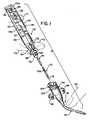
- FIG. 1shows the catheterization system 10 with its two major components (the inserter unit 12 and catheter assembly 18) separated from one another for purposes of illustration.
- the inserter unit 12(which is preferably disposable after use) is made up of a needle assembly 14, a guide wire 16 having an actuator 20 connected to the proximal end thereof and a body 22.
- the needle assembly 14is connected to the body 22, which body 22 also carries the actuator 20 of the guide wire 16.
- the actuator 20is movable along the length of the body 22 to advance the guide wire 16 from its normal retracted position to an extended position as described in detail hereinbelow.
- the actuating lever 20is located such that it may be manipulated by the thumb F1 of the person placing the catheter while the inserter unit 12 is grasped between the forefinger F2 and index finger F3 thereby facilitating one-handed operation of the system 10. Further, there is illustrated a finger F4 placed on the flexible portion of the catheter assembly 18 for the purposes of pinching off blood flow (after the catheter assembly 18 has been inserted into a vessel) to enable attachment of an appropriate stop cock or the like.
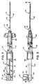
- FIGS. 2-4Prior to use, the catheterization system 10 is in the assembled position shown in FIGS. 2-4, inclusive, in which the inserter unit 12 removably carries the catheter assembly 18 on the needle assembly 14 in an over-the-needle position.
- FIGS. 2-4show the actuator 20 in its normal retracted position at the proximal end of the inserter unit 12. In this retracted position, the distal end of the guide wire 16 is located within the needle assembly 14 as shown in FIG. 8B.
- the needle assembly 14is of a length in relation to the catheter assembly 18 such that when the catheter assembly 18 is on the needle assembly 14 the distal end of the needle assembly 14 (shown to the right in FIGS. 2-4 & 8B) extends beyond the distal end of the catheter assembly 18.
- FIGS. 6A-6DThe catheterization system 10 is constructed from four basic parts which are separately shown in FIGS. 6A-6D prior to assembly of the system 10.
- FIG. 6Ashows the guide wire 16 and its actuator 20.
- the proximal end 16a of the guide wire 16is physically attached to the actuator 20 while the distal end 16b is formed with a rounded (e.g., semi-spherical) tip (See FIG. 8B).
- FIG. 6Bshows the body 22 of the inserter unit 12 which body receives the guide wire 16 and slidably carries its actuator 20.
- Body 22is connected to the needle assembly 14, as shown in FIG. 6C.
- the needle assembly 14,in turn, carries the over-the-needle catheter assembly 18 shown in FIG. 6D.
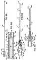
- the body 22, shown in the enlarged cross-section of FIG. 5,includes spaced side walls 24, 26 which, for convenience and ease of handling are slightly rounded or outwardly bowed (see FIGS. 1 and 5), an interconnecting top wall 28 which has a medial and longitudinally extending slot 30 and an interconnecting bottom wall 32. Additionally, the body 22 is formed with internal dividing walls 34, 36 which are appropriately shaped to form two spaced channels 38, 40 which constitute the second or main flashback chamber located within the unit body 22. Specifically, the walls 24, 34 and the contiguous portions of the walls 28, 32 form the elongated channel 38 extending along side wall 24 and visible therethrough, with the channel 40 being similarly formed and likewise being visible through its contiguous external wall 26.
- divider walls 34, 36are shaped along with the top and bottom walls 28, 32 to provide a longitudinally extending medial track 42 which, as seen in FIG. 5, is open through top wall 28 of the body 22 through slot 30 which is substantially coextensive with the track 42.
- the body 22has a proximal end 22a and a distal end 22b. Opening through the proximal end 22a of the unit body 22 are the spaced open proximal ends of the channels 38, 40 designated respectively as 38a, 40a, and the proximal open end 42a of the track 42.
- the proximal ends 38a, 40a of the channels 38, 40are closed against blood flow by porous plugs 44, 46 which enable the purging of air.
- the channels 38, 40communicate with the internal cavity 50, created by the projecting wall 48. Internal cavity 50 receives the proximal end of the needle assembly 14, as will be subsequently described, to complete paths from the distal tip 14b of the needle assembly 14 to the proximal ends 38b, 40b of the channels 38, 40.
- a transverse partition 52Disposed between the distal ends 38b, 40b of the channels 38, 40 and closing off the distal end 42b of the track 42 is a transverse partition 52 which is formed with a guide wire receiving opening 54 through which the guide wire 16 is passed for longitudinal movement relative to the inserter unit 12.
- the fit between the guide wire 16, which has uniform diameter, and the opening 54is such as not to interfere with easy sliding movement thereof but, at the same time, to preclude the flow of blood therethrough and into the track 42 (see FIG. 7).
- track 42is open at its proximal end 42a and along its top as a result of the provision of the longitudinally extending and medially disposed slot 30 in the top wall 28 of the body 22.
- the distal or foremost circular face 52a of the partition 52will, as will subsequently be described, divert the flow of flashback blood into the contiguous distal ends 38b, 40b of the channels 38, 40.
- a relatively short strokee.g. the length of the track 42.
- the guide wire actuator 20includes an upstanding actuating lever 56 which projects above the top wall 28 of the body 22 and is in a position which is readily accessible to the user (see FIG. 1).
- the guide wire actuator 20includes laterally extending stabilizing feet 58, 60 which ride along the flat upper surface 28a of the top wall 28 of the body 22. Projecting downwardly from the stabilizing feet 58,60 is a connecting web 62 which, in turn, carries a cylindrical slide member 64 which is attached to the proximal end 16a of the guide wire 16 for advancing and retracting the guide wire 16 as a result of the movement of the actuator 20 between limit positions.
- the actuator 20is disposed in a fully retracted position shown in FIGS. 2 and 3 and contiguous to the proximal end 22a of the body 22.
- the actuator 20is releasably held in this retracted position by an appropriate detent mechanism 66 located on the connecting web 62 of the actuator 20 and on the upstanding walls of the slot 30.
- the detent mechanism 66may take a variety of forms and here includes outwardly extending projections formed on the opposite upstanding walls of the connecting web 62 which are respectively located between paired positioning projections formed on the upstanding walls of the slot 30 contiguous to the proximal end 22a of the body 22.
- the projectionscoact with each other to hold the actuator 20 in the retracted position at the proximal end 22a of the inserter unit 12.
- the rounded distal tip 16b of the guide wire 16is proximal of the distal tip 14b of the needle assembly 14 and optimally in a clearance position with respect to the most distal port 70d (see FIG. 8B), so as not to inhibit the proper functioning of the system, particularly with respect to early visualization of flashback.
- the entire sub-assembly of the actuator 20 and the guide wire 16may be withdrawn (against the minimal resistance of the detent mechanism 66) from the proximal end 42a of the guideway 42 so that the guide wire 16 and actuator 20 may be separated from the system 10 for use independently of the system.
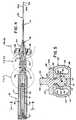
- FIG. 6in conjunction with FIGS. 4 and 7 for an explanation of the needle assembly 14 and the manner in which it is connected to the body 22.
- the needle assembly 14includes an elongated needle body 70 of an appropriate gauge typically in the range of 16-24.
- the needle body 70is mounted at its proximal end 70a on the needle hub 72 and is formed with a bevelled distal tip 70b.
- the needle body 70includes a needle bore 70c of uniform cross-section which receives, with appropriate clearance and as will subsequently be described, the wire guide 16.
- the operative orientation of the needle body 70is with the bevel 70b up.
- the blood ports 70d, along with the catheter assembly 18,provide a first flashback chamber.
- the ports 70d in the needle body 70are spaced proximally of the bevelled tip 70b to provide an intermediate section of the needle body 70 which will cooperate with the catheter 18 to provide an early or first flashback chamber, located between the outside wall of the needle body 70 and inside wall of the catheter assembly 18.
- the spacing of the most distal port 70dis such that only a relatively short path for blood flow exists from the bevelled distal tip 70b of the needle body 70 through the needle bore 70c and into such first of the series of flashback ports 70d.
- the needle hub 72includes a hub body 74 having a proximal end 74a and a distal end 74b. At its distal end 74b, the needle body 74 is formed with a male luer slip or cylindrical supporting plug 76 which is sized for releasable but fluid tight (but not air tight) connection to a female luer lock connector or hub, to be described, on the proximal end of the catheter assembly 18. Contiguous to its proximal end 74a, the hub body 74 is formed with a male needle mounting hub 78 which is sized to be received within the projecting cylindrical wall 48 of the body 22.
- the hub body 74includes a step 80 which is sized to fit into and close off the cavity 50 in the distal end 22b of the body 22, as seen best in FIGS. 4 and 7.
- the hub body 74is provided with an internal cavity 82 which, at its distal end, communicates with the needle bore 70c and, at its proximal end, is formed with ports 84, 86 which establish lateral openings at either side of the partition 52 of the body 22 such that the flashback blood diverted by the surface 52a may flow into the adjacent distal ends 38b, 40b of the channels 38, 40 (See FIG. 7).
- the needle hub body 74is formed with four radially extending finger pieces 88 at 90° circumferential spacings which are appropriately contoured at their outermost edges to provide gripping or finger receiving notches or depressions 90 (see, in particular, FIG.
- the catheter assembly 18is seen to include an elongated catheter body 92 having proximal and distal ends 92a, 92b and an internal lumen or bore 92c.
- the end of the catheter body 92 contiguous to the distal tip 92bis formed with a progressively decreasing cross section or tapered tip to facilitate insertion into the blood vessel.
- the catheter body 92is supported at its proximal end by a catheter hub 94 which is illustrated as having laterally projecting suture wings 96, 98, although it is understood that the catheter hub 94 may be provided with other means (or no means) for the retention of the catheter assembly 18 on the patient after placement.
- the catheter hub 94is formed with an integral female luer lock or connector 100.
- the proximal end of the hub body 74is formed with an orienting key or lug 102 (see FIG. 1) which is received within an appropriately oriented keyway or orienting notch 104 formed in the proximal end of the luer lock or connector 100.
- the disposable inserter unit 12must be fabricated, at least as to those walls which will provide visualization of the content of the channels 38, 40, of a transparent material, typically of a moldable thermoplastic material having the requisite properties to withstand sterilization.
- the needle body 70is formed of an appropriate metal, typically 304 Stainless Steel (S.S.), such that the port 70d, provided for visualization of flashback blood, as will be described, may be ground into the upper surface of the needle body 70.
- the guide wire 16may be fabricated of metal, plastic, or a combination thereof and is constructed to provide its spherical or rounded soft distal tip 16b.
- the catheter body 92includes at least some clear or translucent elongated circumferentially extending sections and may be fabricated from a striped single lumen catheter blank which includes circumferentially extending sectors of clear polyurethane separated by longitudinally extending circumferential filler sections of a radiopacque polyurethane. Any appropriate technique may be utilized for the manufacture of the catheter body or blank to enable visualization of flashback blood in the first or early visualization flashback chamber, as will now be described.
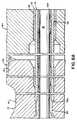
- FIGS. 8A, 8B, 9 and 10for a description of closed-ended annular first or early visualization flashback chamber, generally designated by the reference numeral 106 formed between the catheter body 92 and the needle body 70 when the catheter assembly 18 is carried on the needle assembly 14 in the over-the-needle position.
- the interior of the catheter body 92is provided with a relatively shallow longitudinally extending well 92d having its distal portion 92e located distally of the first flashback port 70d and its proximal end 92f located proximally of the last of the flashback ports 70d formed in the uppermost surface of the needle body 70.
- the wire guide 16when the wire guide 16 is in the retracted position its spherical distal tip 16b is disposed in a non-obstructing or clearance position in relation to the most distal or first blood flashback port 70d encountered by the initial blood flow from the needle bore 70c.
- Various non-obstructing positionscan be established for the wire guide 16 in relation to the first flashback port 70d.
- the distal tip 16b of the wire guide 16is shown substantially intermediate the distal and proximal ends of the first flashback port 70d which is adequate to provide an unobstructed blood path to the first flashback port 70d, with the spherical tip 16b serving as a diverter of the blood flow.
- the specific orientation of the distal tip 16b of the wire guide 16 relative to the needle assembly 14represents a design compromise.
- the design objectiveis to provide a compact and foreshortened system, which requires that the distal tip 16b of the wire guide 16 be as close as practical to the distal end 14b of the needle assembly 14 without interfering with entry of blood into the first flashback chamber 106.
- Flashback visualizationwill occur throughout the length of the first flashback chamber 106 due to the provision of the multiple flashback ports 70d (see FIG. 6).
- the diameter of the wire guide 16is selected in relation to the diameter of the needle bore 70c to provide an annular blood flow passage 108 therebetween which communicates with the first flashback chamber 106 through the spaced ports 70d.
- two flow pathsare established for flashback blood, namely, a first path through the multiple flashback ports 70d and into the first flashback chamber 106 and a second path via the annular blood flow passage 108 extending along the longitudinal extent of the wire guide 16 from its distal tip 16b, into the cavity 82 of the hub body 72, through the lateral ports or windows 84, 86, into the cavity 50 formed at the distal end 22b of the body 22, and thence into the distal ends 38b, 40b of the channels 38, 40 of the second flashback chamber.
- the disposable inserter unit 12is initially assembled by connecting the needle assembly 14 to the body 22, with the step 80 of the needle hub 72 closing off the distal end 22b of the body 22 and with the male needle mounting hub 76 received within the projecting cylindrical wall 48 of the body 22.
- the guide wire 16 and its actuator 20is then assembled on the body 22.
- the guide wire 16is threaded through the partition opening 54 aided by the funnel formed at the distal end 42b of the track 42.
- the guide wire 16is then advanced through the cavity 82 and into the needle bore 70c until the distal tip 16b of the guide wire 16 is spaced proximally of the tip 14b of the needle assembly 14 in its flow diverting position in relation to the first of the ports 70d in the needle body 70 (see FIG 8B).
- the well 92d formed in the interior of the catheter body 92cooperates with the needle body 70 to form the first flashback chamber 106.
- Orientation of the catheter assembly 18 in relation to the needle assembly 14is accomplished by the key 102 entering the orienting notch 104; and, in this position, the distal catheter tip 92b is disposed proximal to the distal needle tip 70b and in the appropriate position in relation to the several ports to form the first flashback chamber 106.
- the actuator 20when the guide wire 16 is in its retracted position the actuator 20 is at the proximal end 22a of the body 22 and is held in this position for packaging, sterilization and shipment by the detent mechanism 66 (see FIG. 1 in which the actuator 20 is in a dotted line position slightly forward of the proper retracted position to generally show the detent mechanism 66).
- the userprepares the puncture site in the usual manner and then peels open the sterilized and sealed package to remove the system 10.
- the system 10is sold with a protective shield (not shown) disposed over the catheter body 92 and the projecting distal tip of the needle assembly 14 and this protective shield is removed.
- the usermay try out the advancement and retracting of the spring wire guide 16 through the needle assembly 14 to ensure proper feeding.
- the usermay make the election of whether or not to utilize the suture wings 96, 98 since, typically, the suture wings can be removed from the catheter hub 94 such that the user may use a different procedure for securing the catheter assembly 18 to the skin of the patient after placement.
- the actuating lever 20is moved to its fully retracted position at the proximal end 22a of the body 22 to properly position the distal tip 16b of the guide wire 16 as shown in FIG. 8B.
- Successful entry into the blood vesselwill be immediately visualized by the appearance of flashback blood initially in the first or early visualization flashback chamber 106 and then in the channels 38, 40 forming the second flashback chamber in the body 22.
- the usermust take care not to inadvertently puncture both vessel walls incident to the introduction of the needle assembly 14 into the blood vessel since this, in turn, could result in the inadvertent sub-arterial placement of the wire guide 16.
- the guide wire 16After stabilizing the position of the needle assembly 14 and careful advancement of the wire guide 16 via the actuating lever 20 (moving through its relatively short forward stroke), the guide wire 16 will be located within the blood vessel for a length predetermined by the permitted stroke of the actuator lever 20. If resistance is encountered while advancing the wire guide 16, the user should not force such feed and should not retract the wire guide 16 while in the blood vessel since this could inadvertently damage the wire guide 16. Rather, the entire system 10 should be withdrawn from the vessel and a new puncture attempted.
- the userAfter the wire guide 16 is positioned, the user firmly grips the body 22 or the needle hub 72 (e.g., at the depressions 90) and then advances the catheter assembly 18 forwardly along and off the needle assembly 14.
- the distal end 92b of the catheter assembly 18tracks the wire guide 16 into the vessel. If difficulty is encountered during catheter advancement, a slight rotation of the catheter hub 94 might be helpful. Thereupon, the user holds the catheter 18 in place and removes the inserter unit 12, at which point the physician attaches the desired stopcock, injection cap or connecting tube to the liner connector 100 of the catheter hub 94.
- the final stepis to secure the catheter to the patient in a preferred method, for example, by using the wings 96, 98 and to cover the puncture site with a suitable dressing.
Landscapes
- Health & Medical Sciences (AREA)
- Life Sciences & Earth Sciences (AREA)
- Public Health (AREA)
- Veterinary Medicine (AREA)
- Biomedical Technology (AREA)
- Heart & Thoracic Surgery (AREA)
- Hematology (AREA)
- Engineering & Computer Science (AREA)
- Animal Behavior & Ethology (AREA)
- General Health & Medical Sciences (AREA)
- Anesthesiology (AREA)
- Vascular Medicine (AREA)
- Biophysics (AREA)
- Pulmonology (AREA)
- Infusion, Injection, And Reservoir Apparatuses (AREA)
- Media Introduction/Drainage Providing Device (AREA)
- Vehicle Body Suspensions (AREA)
- Surgical Instruments (AREA)
- Fluid-Damping Devices (AREA)
- Chair Legs, Seat Parts, And Backrests (AREA)
Abstract
Description
Claims (15)
- A system for introducing an over-the-needlecatheter into a blood vessel comprisinga body (22),a hollow needle body (70) having a proximal end (70a)connected to said body and formed with a distal needle tip(70b) and at least one port (70d) close to said needle tip,a catheter body (92) having a lumen (92c) terminatingat a distal catheter tip (92b), said catheter body adaptedto be carried on said needle body and being dimensioned inrelation to said needle body such that, upon placement ofsaid catheter body over said needle body, said catheterbody and said needle body cooperating to form a firstflashback chamber (106) therebetween, said first chamberbeing in communication with the interior of said needlebody through said port, said catheter body being atleast partially translucent to enable the visualization ofblood flow into said first chamber upon insertion of saidneedle tip into a blood vessel, anda guide wire (16) having adistal end (16b), is slidably mounted in said body andwithin said needle body,characterized in that the guide wire (16) isdimensioned in relation to saidneedle body to provide a blood flow passage therebetween,said guide wire being movable between a first position inwhich its distal end is wholly within said needle body anda second position in which said distal end extends beyondsaid needle tip, and wherein a second flashback chamber(38, 40) is formed in said body and connected to said needle body to receive blood flow upon insertion of saidneedle tip into a blood vessel.
- A system as claimed in Claim 1 wherein when saidguide wire is in said first position, said distal end is ina clearance position with respect to said port.
- A system as claimed in Claim 1 wherein said secondchamber includes venting means (44, 46) to allow air toescape from said second chamber but not blood.
- A system as claimed in Claim 1 wherein said body(22) includes mounting means for slidably receiving saidguide wire including a partition (52) having a guide wireopening (54 ), said guide wire being disposed through saidguide wire opening with a sliding fit which precludes bloodflow therethrough.
- A system as claimed in Claim 4 wherein saidpartition extends in a direction substantially transverseto the path of movement of said guide wire.
- A system as claimed in Claim 5 wherein saidpartition is arranged to divert the flow of flashback bloodfrom said needle body to said second chamber.
- A system as claimed in Claim 4 wherein said bodyincludes a track (42) formed therein and terminating at oneend in said partition, said guide wire having a proximalend (16a) extending into said track and connected to anactuator (20) slidably mounted in said track.
- A system as claimed in Claim 7 in which saidactuator includes a lever which extends external to saidbody for moving said guide wire.
- A system as claimed in Claim 1 whereinsaid catheter body (92) is removably carried on saidneedle body (70);andan inserter unit (12) includes said body (22) havinga blood flashback chamber, (38, 40),said guide wire (16) havingmeans (20) on said body for mounting said guide wirethereon for movement between said retracted position in whichsaid guide wire distal tip is within said needle body andsaid extended position in which said guide wire distal tipextends beyond said needle tip.
- A system as claimed in Claim 9 wherein said meanson said body for mounting said guide wire includes a track(42) formed in said body and an actuator (20) slidablymounted in said track and operatively connected to saidguide wire.
- A system as claimed in Claim 10 wherein said trackhas proximal and distal track ends (42a, 42b) and said bodyincludes a partition closing said distal end of said track, said partition being formed with a partition openingthrough which said guide wire extends, said partitionopening being dimensioned to provide a sliding fit withsaid guide wire whereby said track is effectively blockedfrom receiving flashback blood flowing through into saidflashback chamber.
- A system as claimed in Claim 11 wherein saidproximal track end is opened such that said actuator andguide wire may be removed from said body.
- A system as claimed in Claim 12 including detentmeans (66) on said body and said actuator for releasablyretaining said actuator against movement in said track andretaining said guide wire in said retracted position.
- A system as claimed in Claim 1 wherein a needleassembly (14) includes said hollow needle body (70), said hollow needlebody defining a needle bore (70c) terminating at thedistal needle tip (70b),a catheter assembly (18) includes said catheter body(92),the distal end ofsaid guide wire (16) being, in said retracted position,substantially clear of said port (70d) and contiguous to said needle tip (70b),said needle assembly connected to the body (22),an actuator (20)mounted in said body for movement and operatively connectedto said guide wire for moving said guide wire between itsretracted position and its extended position,pathwaymeans in said body for establishing a blood flow path fromsaid needle bore to said second flashback chamber, saidbody being separable from said catheter assembly after saidcatheter assembly is placed in a blood vessel.
- A system as claimed in Claim 14 wherein saidsecond flashback chamber includes venting means to vent airfrom said second flashback chamber to the atmosphere andretain flashback blood in said second flashback chamber.
Applications Claiming Priority (3)
| Application Number | Priority Date | Filing Date | Title |
|---|---|---|---|
| US07/899,785US5246426A (en) | 1992-06-17 | 1992-06-17 | Catheterization system |
| US899785 | 1992-06-17 | ||
| PCT/US1993/005849WO1993025253A1 (en) | 1992-06-17 | 1993-06-17 | Catheterization system |
Publications (3)
| Publication Number | Publication Date |
|---|---|
| EP0646025A1 EP0646025A1 (en) | 1995-04-05 |
| EP0646025A4 EP0646025A4 (en) | 1995-05-24 |
| EP0646025B1true EP0646025B1 (en) | 1998-04-08 |
Family
ID=25411562
Family Applications (1)
| Application Number | Title | Priority Date | Filing Date |
|---|---|---|---|
| EP93916613AExpired - LifetimeEP0646025B1 (en) | 1992-06-17 | 1993-06-17 | Catheterization system |
Country Status (11)
| Country | Link |
|---|---|
| US (1) | US5246426A (en) |
| EP (1) | EP0646025B1 (en) |
| JP (1) | JPH07507945A (en) |
| AT (1) | ATE164770T1 (en) |
| AU (1) | AU663455B2 (en) |
| CA (1) | CA2134547C (en) |
| DE (1) | DE69317889T2 (en) |
| DK (1) | DK0646025T3 (en) |
| ES (1) | ES2117712T3 (en) |
| WO (1) | WO1993025253A1 (en) |
| ZA (1) | ZA934323B (en) |
Families Citing this family (116)
| Publication number | Priority date | Publication date | Assignee | Title |
|---|---|---|---|---|
| WO1993019679A1 (en)* | 1992-04-07 | 1993-10-14 | The Johns Hopkins University | A percutaneous mechanical fragmentation catheter system |
| ES2105330T3 (en)* | 1992-11-24 | 1997-10-16 | Braun Melsungen Ag | CATHETERIZATION INSTRUMENTAL. |
| US5267971A (en)* | 1993-03-17 | 1993-12-07 | Becton, Dickinson And Company | Catheter introducer with notched needle |
| US5520657A (en)* | 1993-08-09 | 1996-05-28 | Sellers; Jackie | Method and device for vessel location cannulation utilizing a unique needle and syringe device |
| US5366441A (en)* | 1993-09-28 | 1994-11-22 | Becton, Dickinson And Company | Catheter introducer assembly with guidewire |
| USD395501S (en) | 1995-12-07 | 1998-06-23 | Becton Dickinson And Company | Winged catheter |
| US5704914A (en)* | 1996-02-23 | 1998-01-06 | Stocking; John E. | Catheter placement assembly |
| CA2197415A1 (en)* | 1996-02-29 | 1997-08-29 | Kenneth C. Musgrave | Catheter with improved tape down wing |
| US5830190A (en)* | 1996-06-11 | 1998-11-03 | Becton Dickinson And Company | Protected needle catheter placement device having needle placement visualization features and method for its use |
| JP3819491B2 (en)* | 1996-08-20 | 2006-09-06 | 東郷メディキット株式会社 | Puncture needle for catheter introduction |
| DE19731878A1 (en)* | 1997-07-24 | 1999-02-18 | Yilmaz Levent Dipl Ing | Catheterising syringe for blood vessels |
| US6475189B1 (en)* | 1999-12-21 | 2002-11-05 | Ethicon, Inc. | Apparatus and method for a self-blunting safety catheter |
| US6905489B2 (en) | 2001-04-24 | 2005-06-14 | Northgate Technologies, Inc. | Laparoscopic insertion device |
| AU2012200018B9 (en)* | 2001-12-26 | 2014-03-13 | Yale University | Vascular access device |
| DE60235574D1 (en)* | 2001-12-26 | 2010-04-15 | Univ Yale | VESSEL shunt device |
| US20050096594A1 (en)* | 2002-04-30 | 2005-05-05 | Doctor's Research Group, Incorporated | Cannula arrangements |
| EP1440656A3 (en)* | 2003-01-14 | 2004-10-06 | Radi Medical Systems Ab | Device for visually indicating a blood pressure |
| US10413211B2 (en) | 2003-02-21 | 2019-09-17 | 3Dt Holdings, Llc | Systems, devices, and methods for mapping organ profiles |
| US7818053B2 (en) | 2003-02-21 | 2010-10-19 | Dtherapeutics, Llc | Devices, systems and methods for plaque type determination |
| US8078274B2 (en) | 2003-02-21 | 2011-12-13 | Dtherapeutics, Llc | Device, system and method for measuring cross-sectional areas in luminal organs |
| US10172538B2 (en) | 2003-02-21 | 2019-01-08 | 3Dt Holdings, Llc | Body lumen junction localization |
| US7270649B2 (en)* | 2004-07-14 | 2007-09-18 | P. Rowan Smith, Jr. | Intravenous catheter device |
| EP1876972A4 (en)* | 2005-03-30 | 2009-04-01 | Access Scientific Inc | Vascular access |
| EP1907042B1 (en) | 2005-07-06 | 2009-03-11 | Vascular Pathways Inc. | Intravenous catheter insertion device and method of use |
| WO2008005618A2 (en)* | 2006-07-06 | 2008-01-10 | Vascular Pathways, Inc. | Intravenous catheter insertion device and method of use |
| US8784336B2 (en) | 2005-08-24 | 2014-07-22 | C. R. Bard, Inc. | Stylet apparatuses and methods of manufacture |
| US7766937B2 (en)* | 2006-03-13 | 2010-08-03 | Mini-Lap Technologies, Inc. | Minimally invasive surgical assembly and methods |
| JP4925716B2 (en)* | 2006-04-28 | 2012-05-09 | メディキット株式会社 | Indwelling needle assembly |
| US7794407B2 (en) | 2006-10-23 | 2010-09-14 | Bard Access Systems, Inc. | Method of locating the tip of a central venous catheter |
| US8388546B2 (en) | 2006-10-23 | 2013-03-05 | Bard Access Systems, Inc. | Method of locating the tip of a central venous catheter |
| US7922696B2 (en)* | 2007-01-24 | 2011-04-12 | Access Scientific, Inc. | Access device |
| EP3093038B1 (en) | 2007-04-18 | 2019-05-22 | Access Scientific, Inc. | Access device |
| EP2150187A2 (en)* | 2007-04-18 | 2010-02-10 | Access Scientific, Inc. | Access device |
| EP2150304B1 (en)* | 2007-05-07 | 2010-12-01 | Vascular Pathways Inc. | Intravenous catheter insertion and blood sample devices and method of use |
| USD620107S1 (en)* | 2007-09-17 | 2010-07-20 | Q Park Medical Limited | Endoscope sheath assembly |
| EP2200677A1 (en) | 2007-09-17 | 2010-06-30 | ICU Medical, Inc. | Insertion devices for infusion devices |
| US8781555B2 (en) | 2007-11-26 | 2014-07-15 | C. R. Bard, Inc. | System for placement of a catheter including a signal-generating stylet |
| US9521961B2 (en) | 2007-11-26 | 2016-12-20 | C. R. Bard, Inc. | Systems and methods for guiding a medical instrument |
| US10524691B2 (en) | 2007-11-26 | 2020-01-07 | C. R. Bard, Inc. | Needle assembly including an aligned magnetic element |
| US10449330B2 (en) | 2007-11-26 | 2019-10-22 | C. R. Bard, Inc. | Magnetic element-equipped needle assemblies |
| US9649048B2 (en) | 2007-11-26 | 2017-05-16 | C. R. Bard, Inc. | Systems and methods for breaching a sterile field for intravascular placement of a catheter |
| US10751509B2 (en) | 2007-11-26 | 2020-08-25 | C. R. Bard, Inc. | Iconic representations for guidance of an indwelling medical device |
| ES2465915T3 (en) | 2007-11-26 | 2014-06-09 | C.R. Bard, Inc. | Integrated system for intravascular catheter placement |
| US8849382B2 (en) | 2007-11-26 | 2014-09-30 | C. R. Bard, Inc. | Apparatus and display methods relating to intravascular placement of a catheter |
| US9636031B2 (en) | 2007-11-26 | 2017-05-02 | C.R. Bard, Inc. | Stylets for use with apparatus for intravascular placement of a catheter |
| EP2319576A1 (en)* | 2008-03-14 | 2011-05-11 | Access Scientific, Inc. | Access device |
| USD615201S1 (en) | 2008-03-14 | 2010-05-04 | Access Scientific, Inc. | Combined guide wire cap and track |
| US8202251B2 (en) | 2008-03-14 | 2012-06-19 | Access Scientific, Inc. | Access device |
| USD594981S1 (en) | 2008-03-14 | 2009-06-23 | Access Scientific, Inc. | Needle hub |
| USD601242S1 (en) | 2008-03-14 | 2009-09-29 | Access Scientific, Inc. | Access device |
| US9901714B2 (en) | 2008-08-22 | 2018-02-27 | C. R. Bard, Inc. | Catheter assembly including ECG sensor and magnetic assemblies |
| USD601243S1 (en) | 2008-09-10 | 2009-09-29 | Access Scientific, Inc. | Access device |
| USD600793S1 (en) | 2008-09-10 | 2009-09-22 | Access Scientific, Inc. | Access device |
| US8437833B2 (en) | 2008-10-07 | 2013-05-07 | Bard Access Systems, Inc. | Percutaneous magnetic gastrostomy |
| CA2743578A1 (en)* | 2008-11-12 | 2010-05-20 | Access Scientific, Inc. | Access device |
| CN102802720B (en)* | 2009-05-12 | 2015-11-25 | 埃克赛斯科技有限公司 | With the access to plant of valve |
| US9532724B2 (en) | 2009-06-12 | 2017-01-03 | Bard Access Systems, Inc. | Apparatus and method for catheter navigation using endovascular energy mapping |
| JP5795576B2 (en) | 2009-06-12 | 2015-10-14 | バード・アクセス・システムズ,インコーポレーテッド | Method of operating a computer-based medical device that uses an electrocardiogram (ECG) signal to position an intravascular device in or near the heart |
| EP2464407A4 (en) | 2009-08-10 | 2014-04-02 | Bard Access Systems Inc | Devices and methods for endovascular electrography |
| US9326757B2 (en) | 2009-12-31 | 2016-05-03 | Teleflex Medical Incorporated | Surgical instruments for laparoscopic aspiration and retraction |
| US8641677B2 (en) | 2010-01-21 | 2014-02-04 | James T. Rawls | Low-profile intravenous catheter device |
| WO2011097312A1 (en) | 2010-02-02 | 2011-08-11 | C.R. Bard, Inc. | Apparatus and method for catheter navigation and tip location |
| AU2011213558A1 (en) | 2010-02-08 | 2012-09-27 | Access Scientific, Inc. | Access device |
| US10384039B2 (en) | 2010-05-14 | 2019-08-20 | C. R. Bard, Inc. | Catheter insertion device including top-mounted advancement components |
| US8932258B2 (en) | 2010-05-14 | 2015-01-13 | C. R. Bard, Inc. | Catheter placement device and method |
| US11925779B2 (en)* | 2010-05-14 | 2024-03-12 | C. R. Bard, Inc. | Catheter insertion device including top-mounted advancement components |
| US9950139B2 (en) | 2010-05-14 | 2018-04-24 | C. R. Bard, Inc. | Catheter placement device including guidewire and catheter control elements |
| US9872971B2 (en) | 2010-05-14 | 2018-01-23 | C. R. Bard, Inc. | Guidewire extension system for a catheter placement device |
| EP2912999B1 (en) | 2010-05-28 | 2022-06-29 | C. R. Bard, Inc. | Apparatus for use with needle insertion guidance system |
| EP4122385A1 (en) | 2010-05-28 | 2023-01-25 | C. R. Bard, Inc. | Insertion guidance system for needles and medical components |
| BR112013002431B1 (en) | 2010-08-20 | 2021-06-29 | C.R. Bard, Inc | SYSTEM FOR RECONFIRMING THE POSITION OF A CATHETER INSIDE A PATIENT |
| US8801693B2 (en) | 2010-10-29 | 2014-08-12 | C. R. Bard, Inc. | Bioimpedance-assisted placement of a medical device |
| US8690833B2 (en) | 2011-01-31 | 2014-04-08 | Vascular Pathways, Inc. | Intravenous catheter and insertion device with reduced blood spatter |
| ES2835652T3 (en) | 2011-02-25 | 2021-06-22 | Bard Inc C R | Medical component insertion device including a retractable needle |
| USD903101S1 (en) | 2011-05-13 | 2020-11-24 | C. R. Bard, Inc. | Catheter |
| RU2609203C2 (en) | 2011-07-06 | 2017-01-30 | Си.Ар. Бард, Инк. | Determination and calibration of needle length for needle guidance system |
| US8676301B2 (en)* | 2011-07-14 | 2014-03-18 | Med Works Limited | Guide wire incorporating a handle |
| EP2744557B1 (en) | 2011-08-17 | 2021-11-10 | Smiths Medical ASD, Inc. | Access device with valve |
| US10159531B2 (en) | 2012-04-05 | 2018-12-25 | C. R. Bard, Inc. | Apparatus and methods relating to intravascular positioning of distal end of catheter |
| JP2015516846A (en) | 2012-04-05 | 2015-06-18 | バード・アクセス・システムズ,インコーポレーテッド | Device and system for navigating and positioning a central venous catheter within a patient |
| US11759268B2 (en) | 2012-04-05 | 2023-09-19 | C. R. Bard, Inc. | Apparatus and methods relating to intravascular positioning of distal end of catheter |
| WO2014120741A1 (en) | 2013-01-30 | 2014-08-07 | Vascular Pathways, Inc. | Systems and methods for venipuncture and catheter placement |
| US9566087B2 (en) | 2013-03-15 | 2017-02-14 | Access Scientific, Llc | Vascular access device |
| IN2013DE03088A (en)* | 2013-10-17 | 2015-04-24 | Poly Medicure Ltd | |
| EP3071282B1 (en)* | 2013-10-22 | 2021-04-21 | Bernd Tietze | Catheter puncture device |
| USD751195S1 (en) | 2013-10-26 | 2016-03-08 | Medtronic Vascular, Inc. | Guidewire introducer apparatus |
| WO2015120256A2 (en) | 2014-02-06 | 2015-08-13 | C.R. Bard, Inc. | Systems and methods for guidance and placement of an intravascular device |
| WO2016037127A1 (en) | 2014-09-05 | 2016-03-10 | C.R. Bard, Inc. | Catheter insertion device including retractable needle |
| CN104323784A (en)* | 2014-11-19 | 2015-02-04 | 广州健恩医疗设备有限公司 | Y-type blood-return cavity device and artery puncture needle comprising same |
| US10973584B2 (en) | 2015-01-19 | 2021-04-13 | Bard Access Systems, Inc. | Device and method for vascular access |
| US11027099B2 (en) | 2015-04-30 | 2021-06-08 | Smiths Medical Asd, Inc. | Vascular access device |
| USD903100S1 (en) | 2015-05-01 | 2020-11-24 | C. R. Bard, Inc. | Catheter placement device |
| CN113350614A (en)* | 2015-05-15 | 2021-09-07 | C·R·巴德股份有限公司 | Catheter placement device including extendable needle safety feature |
| WO2016210325A1 (en) | 2015-06-26 | 2016-12-29 | C.R. Bard, Inc. | Connector interface for ecg-based catheter positioning system |
| US11000207B2 (en) | 2016-01-29 | 2021-05-11 | C. R. Bard, Inc. | Multiple coil system for tracking a medical device |
| US10493262B2 (en) | 2016-09-12 | 2019-12-03 | C. R. Bard, Inc. | Blood control for a catheter insertion device |
| WO2018089274A1 (en)* | 2016-11-08 | 2018-05-17 | Redsmith, Inc. | Slotted guidewire protector and advancing device and method |
| EP3585471B1 (en) | 2017-03-01 | 2025-01-01 | C. R. Bard, Inc. | Catheter insertion device |
| WO2018191547A1 (en) | 2017-04-14 | 2018-10-18 | Access Scientific, Llc | Vascular access device |
| US10569059B2 (en) | 2018-03-01 | 2020-02-25 | Asspv, Llc | Guidewire retention device |
| ES2980192T3 (en)* | 2018-03-07 | 2024-09-30 | Bard Access Systems Inc | Guidewire advancement and blood reflux systems for a medical device insertion system |
| US11338113B2 (en)* | 2018-06-07 | 2022-05-24 | Becton, Dickinson And Company | Needle position indicator |
| USD921884S1 (en) | 2018-07-27 | 2021-06-08 | Bard Access Systems, Inc. | Catheter insertion device |
| US10992079B2 (en) | 2018-10-16 | 2021-04-27 | Bard Access Systems, Inc. | Safety-equipped connection systems and methods thereof for establishing electrical connections |
| US11351354B2 (en) | 2019-02-20 | 2022-06-07 | Becton, Dickinson And Company | Extension tube clamp providing positive displacement |
| WO2020181229A1 (en)* | 2019-03-07 | 2020-09-10 | Smiths Medical Asd, Inc. | Catheter insertion device with improved flashback response |
| EP3877032A4 (en)* | 2019-04-12 | 2022-01-19 | Teleflex Medical Incorporated | Catheter insertion apparatus with continuous visible flashback |
| CA3151126A1 (en) | 2019-08-19 | 2021-02-25 | Becton, Dickinson And Company | Midline catheter placement device |
| US11559666B2 (en)* | 2019-09-17 | 2023-01-24 | Becton, Dickinson And Company | Blood collection devices, systems, and methods facilitating blood flashback |
| JP2021053173A (en) | 2019-09-30 | 2021-04-08 | 日立金属株式会社 | Braided tube |
| WO2021183436A1 (en)* | 2020-03-10 | 2021-09-16 | Merit Medical Systems, Inc. | Arterial access needle with proximal port |
| US12377248B2 (en)* | 2020-03-23 | 2025-08-05 | Becton, Dickinson And Company | Vascular access device assembly facilitating single-handed probe advancement with a support member |
| BR112022020323A2 (en)* | 2020-04-20 | 2022-12-13 | Bard Access Systems Inc | QUICK-INSERTION CENTRAL CATHETERS INCLUDING CATHETER SETS AND METHODS THEREOF |
| US11903663B2 (en) | 2021-08-24 | 2024-02-20 | Hyperion Surgical, Inc. | Robotic systems, devices, and methods for vascular access |
| US11678944B1 (en) | 2022-08-23 | 2023-06-20 | Hyperion Surgical, Inc. | Manipulators and cartridges for robotic-assisted vascular access |
| WO2025063062A1 (en)* | 2023-09-19 | 2025-03-27 | テルモ株式会社 | Shape holding device |
Family Cites Families (11)
| Publication number | Priority date | Publication date | Assignee | Title |
|---|---|---|---|---|
| US4317445A (en)* | 1980-03-31 | 1982-03-02 | Baxter Travenol Laboratories, Inc. | Catheter insertion unit with separate flashback indication for the cannula |
| US4417886A (en)* | 1981-11-05 | 1983-11-29 | Arrow International, Inc. | Catheter introduction set |
| ES533509A1 (en)* | 1983-07-18 | 1985-09-01 | Abbott Lab | Catheter flashback indicator. |
| US4525157A (en)* | 1983-07-28 | 1985-06-25 | Manresa, Inc. | Closed system catheter with guide wire |
| US4655750A (en)* | 1985-11-22 | 1987-04-07 | Manresa, Inc. | Closed system catheter with guide wire |
| US4772264A (en)* | 1986-06-23 | 1988-09-20 | Regents Of The University Of Minnesota | Catheter introduction set |
| US4863431A (en)* | 1988-03-03 | 1989-09-05 | Vaillancourt Vincent L | Catheter assembly |
| US4952207A (en)* | 1988-07-11 | 1990-08-28 | Critikon, Inc. | I.V. catheter with self-locating needle guard |
| US4894052A (en)* | 1988-08-22 | 1990-01-16 | Becton, Dickinson And Company | Flash detection in an over the needle catheter with a restricted needle bore |
| US4961729A (en)* | 1988-12-13 | 1990-10-09 | Vaillancourt Vincent L | Catheter insertion assembly |
| US5120319A (en)* | 1991-06-26 | 1992-06-09 | Critikon, Inc. | Flash tube for intravenous catheter |
- 1992
- 1992-06-17USUS07/899,785patent/US5246426A/ennot_activeExpired - Lifetime
- 1993
- 1993-06-17ZAZA934323Apatent/ZA934323B/enunknown
- 1993-06-17ESES93916613Tpatent/ES2117712T3/ennot_activeExpired - Lifetime
- 1993-06-17JPJP6501825Apatent/JPH07507945A/enactivePending
- 1993-06-17AUAU46407/93Apatent/AU663455B2/ennot_activeCeased
- 1993-06-17EPEP93916613Apatent/EP0646025B1/ennot_activeExpired - Lifetime
- 1993-06-17WOPCT/US1993/005849patent/WO1993025253A1/enactiveIP Right Grant
- 1993-06-17ATAT93916613Tpatent/ATE164770T1/ennot_activeIP Right Cessation
- 1993-06-17CACA002134547Apatent/CA2134547C/ennot_activeExpired - Lifetime
- 1993-06-17DEDE69317889Tpatent/DE69317889T2/ennot_activeExpired - Lifetime
- 1993-06-17DKDK93916613Tpatent/DK0646025T3/enactive
Also Published As
| Publication number | Publication date |
|---|---|
| ATE164770T1 (en) | 1998-04-15 |
| JPH07507945A (en) | 1995-09-07 |
| EP0646025A4 (en) | 1995-05-24 |
| ZA934323B (en) | 1996-02-16 |
| AU663455B2 (en) | 1995-10-05 |
| DE69317889D1 (en) | 1998-05-14 |
| DK0646025T3 (en) | 1999-01-18 |
| AU4640793A (en) | 1994-01-04 |
| DE69317889T2 (en) | 1998-09-03 |
| ES2117712T3 (en) | 1998-08-16 |
| US5246426A (en) | 1993-09-21 |
| EP0646025A1 (en) | 1995-04-05 |
| CA2134547C (en) | 1998-07-14 |
| WO1993025253A1 (en) | 1993-12-23 |
| CA2134547A1 (en) | 1993-12-23 |
Similar Documents
| Publication | Publication Date | Title |
|---|---|---|
| EP0646025B1 (en) | Catheterization system | |
| CN113348010B (en) | Continuous visible flashback catheterization apparatus | |
| US20210008347A1 (en) | Catheter assembly with segmented stabilization system | |
| US4655750A (en) | Closed system catheter with guide wire | |
| US11260204B2 (en) | Spring retract IV catheter | |
| JP5166239B2 (en) | Vascular access | |
| US5935110A (en) | Control forward/flashback forward one hand introducer needle and catheter assembly | |
| US5695479A (en) | Instrument, system, kit and method for catheterization procedures | |
| US5512052A (en) | Catheterization set | |
| US4525157A (en) | Closed system catheter with guide wire | |
| US20200197682A1 (en) | Access device with guidewire and related methods | |
| US4894052A (en) | Flash detection in an over the needle catheter with a restricted needle bore | |
| EP0440479B1 (en) | Catheter with controlled valve | |
| US4826492A (en) | Medical probe | |
| EP1331956B1 (en) | Safety introducer apparatus and method therefor | |
| US6623456B1 (en) | Needle member with off-set flash chamber and/or display member | |
| US6974423B2 (en) | Needle assembly | |
| EP0331318A1 (en) | A catheter assembly | |
| WO2006027923A1 (en) | Indwelling needle assembly | |
| KR20040093373A (en) | Combined needle and dilator device for central venous and arterial catheterization | |
| US12280225B2 (en) | Catheter with threading flash confirmation | |
| US3685513A (en) | Indwelling catheter with breakaway needle and lanyard advancing means | |
| CA2097659A1 (en) | Catheter with needle guard and extended flash chamber | |
| WO2024249259A1 (en) | Cutting device and related systems and methods |
Legal Events
| Date | Code | Title | Description |
|---|---|---|---|
| PUAI | Public reference made under article 153(3) epc to a published international application that has entered the european phase | Free format text:ORIGINAL CODE: 0009012 | |
| 17P | Request for examination filed | Effective date:19941028 | |
| AK | Designated contracting states | Kind code of ref document:A1 Designated state(s):AT BE CH DE DK ES FR GB GR IE IT LI LU MC NL PT SE | |
| A4 | Supplementary search report drawn up and despatched | Effective date:19950406 | |
| AK | Designated contracting states | Kind code of ref document:A4 Designated state(s):AT BE CH DE DK ES FR GB GR IE IT LI LU MC NL PT SE | |
| 17Q | First examination report despatched | Effective date:19960709 | |
| GRAG | Despatch of communication of intention to grant | Free format text:ORIGINAL CODE: EPIDOS AGRA | |
| GRAG | Despatch of communication of intention to grant | Free format text:ORIGINAL CODE: EPIDOS AGRA | |
| GRAH | Despatch of communication of intention to grant a patent | Free format text:ORIGINAL CODE: EPIDOS IGRA | |
| GRAH | Despatch of communication of intention to grant a patent | Free format text:ORIGINAL CODE: EPIDOS IGRA | |
| RAP1 | Party data changed (applicant data changed or rights of an application transferred) | Owner name:ARROW INTERNATIONAL INVESTMENT CORP. | |
| GRAA | (expected) grant | Free format text:ORIGINAL CODE: 0009210 | |
| PGFP | Annual fee paid to national office [announced via postgrant information from national office to epo] | Ref country code:SE Payment date:19980407 Year of fee payment:6 | |
| AK | Designated contracting states | Kind code of ref document:B1 Designated state(s):AT BE CH DE DK ES FR GB GR IE IT LI LU MC NL PT SE | |
| REF | Corresponds to: | Ref document number:164770 Country of ref document:AT Date of ref document:19980415 Kind code of ref document:T | |
| REG | Reference to a national code | Ref country code:CH Ref legal event code:NV Representative=s name:MICHELI & CIE INGENIEURS-CONSEILS Ref country code:CH Ref legal event code:EP | |
| PGFP | Annual fee paid to national office [announced via postgrant information from national office to epo] | Ref country code:LU Payment date:19980427 Year of fee payment:6 | |
| PGFP | Annual fee paid to national office [announced via postgrant information from national office to epo] | Ref country code:AT Payment date:19980428 Year of fee payment:6 | |
| PGFP | Annual fee paid to national office [announced via postgrant information from national office to epo] | Ref country code:MC Payment date:19980506 Year of fee payment:6 | |
| ET | Fr: translation filed | ||
| PGFP | Annual fee paid to national office [announced via postgrant information from national office to epo] | Ref country code:BE Payment date:19980512 Year of fee payment:6 | |
| REF | Corresponds to: | Ref document number:69317889 Country of ref document:DE Date of ref document:19980514 | |
| PGFP | Annual fee paid to national office [announced via postgrant information from national office to epo] | Ref country code:DK Payment date:19980525 Year of fee payment:6 | |
| PGFP | Annual fee paid to national office [announced via postgrant information from national office to epo] | Ref country code:IE Payment date:19980526 Year of fee payment:6 Ref country code:CH Payment date:19980526 Year of fee payment:6 | |
| PGFP | Annual fee paid to national office [announced via postgrant information from national office to epo] | Ref country code:PT Payment date:19980605 Year of fee payment:6 | |
| ITF | It: translation for a ep patent filed | ||
| REG | Reference to a national code | Ref country code:IE Ref legal event code:FG4D Free format text:79709 | |
| REG | Reference to a national code | Ref country code:PT Ref legal event code:SC4A Free format text:AVAILABILITY OF NATIONAL TRANSLATION Effective date:19980422 | |
| REG | Reference to a national code | Ref country code:ES Ref legal event code:FG2A Ref document number:2117712 Country of ref document:ES Kind code of ref document:T3 | |
| REG | Reference to a national code | Ref country code:DK Ref legal event code:T3 | |
| PLBE | No opposition filed within time limit | Free format text:ORIGINAL CODE: 0009261 | |
| STAA | Information on the status of an ep patent application or granted ep patent | Free format text:STATUS: NO OPPOSITION FILED WITHIN TIME LIMIT | |
| 26N | No opposition filed | ||
| PG25 | Lapsed in a contracting state [announced via postgrant information from national office to epo] | Ref country code:LU Free format text:LAPSE BECAUSE OF NON-PAYMENT OF DUE FEES Effective date:19990617 Ref country code:IE Free format text:LAPSE BECAUSE OF NON-PAYMENT OF DUE FEES Effective date:19990617 Ref country code:AT Free format text:LAPSE BECAUSE OF NON-PAYMENT OF DUE FEES Effective date:19990617 | |
| PG25 | Lapsed in a contracting state [announced via postgrant information from national office to epo] | Ref country code:SE Free format text:THE PATENT HAS BEEN ANNULLED BY A DECISION OF A NATIONAL AUTHORITY Effective date:19990629 | |
| PG25 | Lapsed in a contracting state [announced via postgrant information from national office to epo] | Ref country code:LI Free format text:LAPSE BECAUSE OF NON-PAYMENT OF DUE FEES Effective date:19990630 Ref country code:DK Free format text:LAPSE BECAUSE OF NON-PAYMENT OF DUE FEES Effective date:19990630 Ref country code:CH Free format text:LAPSE BECAUSE OF NON-PAYMENT OF DUE FEES Effective date:19990630 Ref country code:BE Free format text:LAPSE BECAUSE OF NON-PAYMENT OF DUE FEES Effective date:19990630 | |
| BERE | Be: lapsed | Owner name:ARROW INTERNATIONAL INVESTMENT CORP. Effective date:19990630 | |
| PG25 | Lapsed in a contracting state [announced via postgrant information from national office to epo] | Ref country code:PT Free format text:LAPSE BECAUSE OF NON-PAYMENT OF DUE FEES Effective date:19991231 Ref country code:MC Free format text:LAPSE BECAUSE OF NON-PAYMENT OF DUE FEES Effective date:19991231 | |
| REG | Reference to a national code | Ref country code:CH Ref legal event code:PL | |
| EUG | Se: european patent has lapsed | Ref document number:93916613.8 | |
| REG | Reference to a national code | Ref country code:DK Ref legal event code:EBP | |
| REG | Reference to a national code | Ref country code:PT Ref legal event code:MM4A Free format text:LAPSE DUE TO NON-PAYMENT OF FEES Effective date:19991231 | |
| REG | Reference to a national code | Ref country code:IE Ref legal event code:MM4A | |
| REG | Reference to a national code | Ref country code:GB Ref legal event code:IF02 | |
| PGFP | Annual fee paid to national office [announced via postgrant information from national office to epo] | Ref country code:ES Payment date:20100628 Year of fee payment:18 | |
| PGFP | Annual fee paid to national office [announced via postgrant information from national office to epo] | Ref country code:NL Payment date:20100624 Year of fee payment:18 | |
| PGFP | Annual fee paid to national office [announced via postgrant information from national office to epo] | Ref country code:GR Payment date:20100628 Year of fee payment:18 | |
| REG | Reference to a national code | Ref country code:NL Ref legal event code:V1 Effective date:20120101 | |
| REG | Reference to a national code | Ref country code:GR Ref legal event code:ML Ref document number:980401019 Country of ref document:GR Effective date:20120105 | |
| PG25 | Lapsed in a contracting state [announced via postgrant information from national office to epo] | Ref country code:GR Free format text:LAPSE BECAUSE OF NON-PAYMENT OF DUE FEES Effective date:20120105 Ref country code:NL Free format text:LAPSE BECAUSE OF NON-PAYMENT OF DUE FEES Effective date:20120101 | |
| PGFP | Annual fee paid to national office [announced via postgrant information from national office to epo] | Ref country code:DE Payment date:20120627 Year of fee payment:20 | |
| PGFP | Annual fee paid to national office [announced via postgrant information from national office to epo] | Ref country code:GB Payment date:20120625 Year of fee payment:20 Ref country code:FR Payment date:20120705 Year of fee payment:20 | |
| PGFP | Annual fee paid to national office [announced via postgrant information from national office to epo] | Ref country code:IT Payment date:20120622 Year of fee payment:20 | |
| REG | Reference to a national code | Ref country code:ES Ref legal event code:FD2A Effective date:20121116 | |
| PG25 | Lapsed in a contracting state [announced via postgrant information from national office to epo] | Ref country code:ES Free format text:LAPSE BECAUSE OF NON-PAYMENT OF DUE FEES Effective date:20110618 | |
| REG | Reference to a national code | Ref country code:DE Ref legal event code:R071 Ref document number:69317889 Country of ref document:DE | |
| REG | Reference to a national code | Ref country code:GB Ref legal event code:PE20 Expiry date:20130616 | |
| PG25 | Lapsed in a contracting state [announced via postgrant information from national office to epo] | Ref country code:GB Free format text:LAPSE BECAUSE OF EXPIRATION OF PROTECTION Effective date:20130616 Ref country code:DE Free format text:LAPSE BECAUSE OF EXPIRATION OF PROTECTION Effective date:20130618 |