EP0642328B1 - Joint prosthesis - Google Patents
Joint prosthesisDownload PDFInfo
- Publication number
- EP0642328B1 EP0642328B1EP93910530AEP93910530AEP0642328B1EP 0642328 B1EP0642328 B1EP 0642328B1EP 93910530 AEP93910530 AEP 93910530AEP 93910530 AEP93910530 AEP 93910530AEP 0642328 B1EP0642328 B1EP 0642328B1
- Authority
- EP
- European Patent Office
- Prior art keywords
- joint
- fixture
- joint prosthesis
- plate
- screw
- Prior art date
- Legal status (The legal status is an assumption and is not a legal conclusion. Google has not performed a legal analysis and makes no representation as to the accuracy of the status listed.)
- Expired - Lifetime
Links
- 210000000629knee jointAnatomy0.000claimsabstractdescription23
- 210000000988bone and boneAnatomy0.000claimsdescription55
- 238000004873anchoringMethods0.000claimsdescription10
- 239000000463materialSubstances0.000claimsdescription10
- RTAQQCXQSZGOHL-UHFFFAOYSA-NTitaniumChemical compound[Ti]RTAQQCXQSZGOHL-UHFFFAOYSA-N0.000claimsdescription4
- 239000010936titaniumSubstances0.000claimsdescription4
- 229910052719titaniumInorganic materials0.000claimsdescription4
- VYZAMTAEIAYCRO-UHFFFAOYSA-NChromiumChemical compound[Cr]VYZAMTAEIAYCRO-UHFFFAOYSA-N0.000claimsdescription3
- 229910000531Co alloyInorganic materials0.000claimsdescription3
- 229910000599Cr alloyInorganic materials0.000claimsdescription3
- 239000004699Ultra-high molecular weight polyethyleneSubstances0.000claimsdescription3
- 239000011651chromiumSubstances0.000claimsdescription3
- 239000010941cobaltSubstances0.000claimsdescription3
- GUTLYIVDDKVIGB-UHFFFAOYSA-Ncobalt atomChemical compound[Co]GUTLYIVDDKVIGB-UHFFFAOYSA-N0.000claimsdescription3
- 238000010079rubber tappingMethods0.000claimsdescription3
- 229920000785ultra high molecular weight polyethylenePolymers0.000claimsdescription3
- 229910001182Mo alloyInorganic materials0.000claimsdescription2
- 239000000919ceramicSubstances0.000claimsdescription2
- 239000000788chromium alloySubstances0.000claims1
- 229910017052cobaltInorganic materials0.000claims1
- 230000000295complement effectEffects0.000claims1
- 238000006073displacement reactionMethods0.000claims1
- 238000002513implantationMethods0.000claims1
- 238000002271resectionMethods0.000claims1
- 210000002303tibiaAnatomy0.000abstractdescription29
- 238000001356surgical procedureMethods0.000abstractdescription2
- 238000005520cutting processMethods0.000description20
- 238000000034methodMethods0.000description14
- 238000010883osseointegrationMethods0.000description12
- 238000005553drillingMethods0.000description8
- 210000000689upper legAnatomy0.000description7
- 238000003780insertionMethods0.000description5
- 230000037431insertionEffects0.000description5
- 230000035876healingEffects0.000description4
- 230000010354integrationEffects0.000description4
- 210000003127kneeAnatomy0.000description4
- 210000002414legAnatomy0.000description3
- 210000003041ligamentAnatomy0.000description3
- 210000004417patellaAnatomy0.000description3
- 238000002360preparation methodMethods0.000description3
- 238000003466weldingMethods0.000description3
- 230000001054cortical effectEffects0.000description2
- 230000001627detrimental effectEffects0.000description2
- 239000007943implantSubstances0.000description2
- 239000004033plasticSubstances0.000description2
- 229920003023plasticPolymers0.000description2
- 208000006386Bone ResorptionDiseases0.000description1
- 235000010627Phaseolus vulgarisNutrition0.000description1
- 244000046052Phaseolus vulgarisSpecies0.000description1
- 210000003423ankleAnatomy0.000description1
- 210000001264anterior cruciate ligamentAnatomy0.000description1
- 230000024279bone resorptionEffects0.000description1
- 229910052804chromiumInorganic materials0.000description1
- 230000001419dependent effectEffects0.000description1
- 238000009826distributionMethods0.000description1
- 230000000694effectsEffects0.000description1
- 210000002683footAnatomy0.000description1
- 230000002452interceptive effectEffects0.000description1
- 238000004519manufacturing processMethods0.000description1
- 238000005259measurementMethods0.000description1
- 230000005499meniscusEffects0.000description1
- 229910052751metalInorganic materials0.000description1
- 239000002184metalSubstances0.000description1
- 210000005036nerveAnatomy0.000description1
- 210000001519tissueAnatomy0.000description1
Images


Classifications
- A—HUMAN NECESSITIES
- A61—MEDICAL OR VETERINARY SCIENCE; HYGIENE
- A61B—DIAGNOSIS; SURGERY; IDENTIFICATION
- A61B17/00—Surgical instruments, devices or methods
- A61B17/56—Surgical instruments or methods for treatment of bones or joints; Devices specially adapted therefor
- A61B17/58—Surgical instruments or methods for treatment of bones or joints; Devices specially adapted therefor for osteosynthesis, e.g. bone plates, screws or setting implements
- A61B17/68—Internal fixation devices, including fasteners and spinal fixators, even if a part thereof projects from the skin
- A61B17/84—Fasteners therefor or fasteners being internal fixation devices
- A61B17/86—Pins or screws or threaded wires; nuts therefor
- A61B17/8605—Heads, i.e. proximal ends projecting from bone
- A—HUMAN NECESSITIES
- A61—MEDICAL OR VETERINARY SCIENCE; HYGIENE
- A61B—DIAGNOSIS; SURGERY; IDENTIFICATION
- A61B17/00—Surgical instruments, devices or methods
- A61B17/56—Surgical instruments or methods for treatment of bones or joints; Devices specially adapted therefor
- A61B17/58—Surgical instruments or methods for treatment of bones or joints; Devices specially adapted therefor for osteosynthesis, e.g. bone plates, screws or setting implements
- A61B17/68—Internal fixation devices, including fasteners and spinal fixators, even if a part thereof projects from the skin
- A61B17/84—Fasteners therefor or fasteners being internal fixation devices
- A61B17/86—Pins or screws or threaded wires; nuts therefor
- A61B17/8625—Shanks, i.e. parts contacting bone tissue
- A—HUMAN NECESSITIES
- A61—MEDICAL OR VETERINARY SCIENCE; HYGIENE
- A61F—FILTERS IMPLANTABLE INTO BLOOD VESSELS; PROSTHESES; DEVICES PROVIDING PATENCY TO, OR PREVENTING COLLAPSING OF, TUBULAR STRUCTURES OF THE BODY, e.g. STENTS; ORTHOPAEDIC, NURSING OR CONTRACEPTIVE DEVICES; FOMENTATION; TREATMENT OR PROTECTION OF EYES OR EARS; BANDAGES, DRESSINGS OR ABSORBENT PADS; FIRST-AID KITS
- A61F2/00—Filters implantable into blood vessels; Prostheses, i.e. artificial substitutes or replacements for parts of the body; Appliances for connecting them with the body; Devices providing patency to, or preventing collapsing of, tubular structures of the body, e.g. stents
- A61F2/02—Prostheses implantable into the body
- A61F2/30—Joints
- A61F2/38—Joints for elbows or knees
- A61F2/3868—Joints for elbows or knees with sliding tibial bearing
- A—HUMAN NECESSITIES
- A61—MEDICAL OR VETERINARY SCIENCE; HYGIENE
- A61F—FILTERS IMPLANTABLE INTO BLOOD VESSELS; PROSTHESES; DEVICES PROVIDING PATENCY TO, OR PREVENTING COLLAPSING OF, TUBULAR STRUCTURES OF THE BODY, e.g. STENTS; ORTHOPAEDIC, NURSING OR CONTRACEPTIVE DEVICES; FOMENTATION; TREATMENT OR PROTECTION OF EYES OR EARS; BANDAGES, DRESSINGS OR ABSORBENT PADS; FIRST-AID KITS
- A61F2/00—Filters implantable into blood vessels; Prostheses, i.e. artificial substitutes or replacements for parts of the body; Appliances for connecting them with the body; Devices providing patency to, or preventing collapsing of, tubular structures of the body, e.g. stents
- A61F2/02—Prostheses implantable into the body
- A61F2/30—Joints
- A61F2/30767—Special external or bone-contacting surface, e.g. coating for improving bone ingrowth
- A61F2/30771—Special external or bone-contacting surface, e.g. coating for improving bone ingrowth applied in original prostheses, e.g. holes or grooves
- A61F2002/30878—Special external or bone-contacting surface, e.g. coating for improving bone ingrowth applied in original prostheses, e.g. holes or grooves with non-sharp protrusions, for instance contacting the bone for anchoring, e.g. keels, pegs, pins, posts, shanks, stems, struts
- A61F2002/30891—Plurality of protrusions
- A61F2002/30892—Plurality of protrusions parallel
- A—HUMAN NECESSITIES
- A61—MEDICAL OR VETERINARY SCIENCE; HYGIENE
- A61F—FILTERS IMPLANTABLE INTO BLOOD VESSELS; PROSTHESES; DEVICES PROVIDING PATENCY TO, OR PREVENTING COLLAPSING OF, TUBULAR STRUCTURES OF THE BODY, e.g. STENTS; ORTHOPAEDIC, NURSING OR CONTRACEPTIVE DEVICES; FOMENTATION; TREATMENT OR PROTECTION OF EYES OR EARS; BANDAGES, DRESSINGS OR ABSORBENT PADS; FIRST-AID KITS
- A61F2/00—Filters implantable into blood vessels; Prostheses, i.e. artificial substitutes or replacements for parts of the body; Appliances for connecting them with the body; Devices providing patency to, or preventing collapsing of, tubular structures of the body, e.g. stents
- A61F2/02—Prostheses implantable into the body
- A61F2/30—Joints
- A61F2/38—Joints for elbows or knees
- A61F2002/3895—Joints for elbows or knees unicompartimental
Definitions
- the inventionrelates to a joint prosthesis for permanent anchorage in the bone tissue of one of the articulatory parts of a joint in the human body, in particular the tibia side of a knee joint, wherein the prosthesis comprises a flat, plate-like element having an elongate fixture portion.
- a knee joint prosthesis having the pre-characterising features of claim 1is found in FR-A-2630640.
- the elongate fixtures of this prosthesis when implantedare oriented parallel to the main articulation plane of the knee joint. This is also the case for the elongate fixtures of the knee joint prosthesis made known in US-A-4919671.
- the present inventionprovides a solution to these drawbacks by providing a joint prosthesis, the essential features of which are defined in claim 1.
- Figs 1 - 14 of the accompanying drawingsrelate to the fitting of uni-condylar and bi-condylar knee joint prostheses having the features of the pre-characterising part of claim 1.
- the elongate fixture(s) of these prosthesesare oriented parallel to the sagittal plane during normal articulation movements of the knee joint in contrast to the elongate fixture(s) of a knee joint prosthesis in accordance with the invention which will be oriented at an angle to the sagittal plane during normal articulation movements of the knee joint, as in the embodiments of the invention described hereinafter with reference to Figs 15 - 19 of the accompanying drawings.
- the prostheses described with reference to Figs 1 - 14serve to illustrate a fitting procedure which may be adapted to fit a prosthesis of the invention as well as various features thereof.
- the patientPrior to performing the fitting operation, the patient will have already undergone a pre-operational X-ray study and planning phase, during which the required measurements and parameters for the prosthesis will have been determined.
- the parametersarrived at allow the correct selection of dimensions for the prosthesis elements which are of course manufactured prior to the surgical operation.
- Fig.1depicts a typical tibia bone 1 from a human leg to which a prosthesis is to be fitted. It should be understood that the bone preparation and prosthesis fitting steps described hereinafter are all carried out during one and the same surgical operation.
- the tibiamust be prepared before fitting of the prosthesis is possible.
- the first step in the operationis to drill a hole 2 all the way through the tibia starting at the front of the bone. Whilst the choice of hole bore dimension is to some extent optional within limits, a hole with approximately 8mm diameter has been found to be satisfactory. However, the actual hole diameter chosen must be such that the hole bore closely corresponds to the diameter of the elongate fixture portion of the prosthesis replacement chosen.
- the hole 2 to be drilled in the bonewill be in an area of healthy bone such that good osseointegration will take place.
- Prior methodshave meant that part of the fixture portion has often been in a portion of the bone which is not healthy.
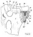
- the next step in the operationis to remove a uni-condylar quadrant 3 as shown in Fig.1.
- the resulting bone appearanceis depicted in Figs.2 and 3 which show respectively plan and side views of a thus-prepared tibia.
- the quadrant 3can be removed by several methods but, to provide accurate guidance and to ensure that the surfaces 3' and 3'' are orthogonal to each other, it is preferred to use the apparatus shown in Fig.4 which comprises an L-shaped block 4, having vertical and horizontal slots 5,6 therein which act as true guiding surfaces for the saw elements 7 and 8 which are used to saw out the quadrant of uni-condylar bone 3.
- the block 4is of course mounted slidably on a guide 9 and clamped by a clamp 4' in position.
- the clampalso allows a pivotal movement of the guide rod 9 such that the lower open positioning portion 9' can be secured against the ankle part of the patient's leg. This pivotal and longitudinal freedom allows the same apparatus to be used for different leg widths and sizes.
- a further guiding devicein the form of a cylindrical projection 10, formed integrally with the L-shaped block and which is a good fit in the hole 2 previously drilled in the tibia.
- the cuts made by the saware fairly accurate, but to provide a smooth surface to which the prosthesis is to be secured, the surfaces 3' and 3'' must first be filed flat. This is performed using the file 11 shown in Fig.5(a) which has its elongate cylindrical portion inserted into a guide element 12 placed, for this purpose, in the hole 2 already made in the tibia.
- the file 11is replaced by a further file 13, as shown in Fig.5(b), the file having a planar lower surface provided however with spline-cutting or serration-cutting file elements 14. It is noted here for information that the splines or serrations might also be referred to as "rifling". Additionally, the file 13 is foreseen with further splines or serrations 15 attached to a vertically extending plate or flange portion.
- the spline-cutting or serration-cutting surfaces 14 and 15 of the fileare so arranged that the splines or serrations are cut to the required depth by a single movement of the file across the bone surfaces, such that the trailing edges of the file pass across the whole bone surface.
- the lower surface of the file 13is foreseen with a series of cutting elements arranged along each of the spline-cutting surfaces 14, 15.
- the cutting elementswill have a negative angle (i.e. they slope top-to-bottom towards the cutting direction) and will increase in depth along each of the elements 14 and 15.
- the height of the first cutting elements at the leading edge of the filewill be minimal and the height of the cutting elements will increase successively towards the trailing edge, up to a height corresponding to the desired final spline channel depth.
- a further file 16is now inserted via its tubular portion into the hole 2.
- the cutting portions 17 on this filesimilar to those on the previous file 13 are then slowly worked into the hole 2 surface whilst the horizontal and vertical plate portions of the file 16 lie against the cut surfaces 3' and 3'' in order to act as guiding elements. In this manner horizontal spline channels or serrations are made in the surface of the drilled hole 2.
- a double operation drilling sequenceis now required to allow insertion of the screw fixture 20 shown in position in Fig.6 .
- This screw fixturehas the purpose of providing a threaded bore for a screw 21 which is inserted into the horizontal plate-like element of the prosthesis via a hole which has been countersunk from the top of the plate and thereby holds in position the plate like element of the prosthesis.
- a small diameter holeis first drilled to receive the lower threaded portion 20'' of the fixing screw 20. Then, in a second operation, a larger diameter drilling is made to receive upper threaded portion 20' of the fixture 20.
- the first drilling operationpasses through both the soft part of the bone (cancellous bone) and the hard exterior surface (cortical bone) such that the screw fixture 20 passes all the way through the outer surface.
- a sloping surfaceis normally provided between the upper 20' and lower 20'' sections of the drilling.
- the tibiais now ready for insertion of the screw fixture 20, into the hole foreseen therefor.
- the screw fixtureis normally constructed from commercially-pure titanium and is self-tapping, the cutting surfaces of this fixture being visible for example on the thinner end of the fixture, just protruding through the cortical bone.
- the end 20''' of the fixture 20is rounded, as are also at least the lower exposed threads. This ensures that, once fitted, no damage will occur to the surrounding tissue due to a sharp surface of the screw fixture which extends all the way through the outside of the bone such that the threaded portion of the fixture is visible.
- the screw 21can then be inserted through the countersunk hole and into the screw fixture.
- the screwis then tightened to hold the plate/fixture 30, 31 of the prosthesis in position.
- the countersunk holewill have been drilled, prior to the operation, in either an area of the plate-like element not having splines or serrations or one which does have splines or serrations. The most preferred form would however be one where the hole is in an area without serrations or splines.
- tube-like fixture element (31)Whilst the tube-like fixture element (31) is depicted as being directly attached to the plate-like element it would also be possible to connect the two elements 30 and 31 via a continuous rib or series of posts forming a discontinuous rib (as is explained hereinafter with reference to a bi-condylar prosthesis).
- the top of the screw fixtureis substantially flush with the upper surface of the bone (i.e. surface 3'') before insertion of the plate 30 and fixture 31. Whilst this flush relationship can be achieved by using a level surface prior to fitting of the plate/fixture 30, 31, this is only the case if the screw hole in the plate-like element 30 is located in an area where there are no splines or serrations laterally (i.e. in the direction of insertion) of the hole. It is thus preferred that the screw hole will be located in an area of the plate without splines or serrations.
- the screw fixturewill be screwed down into the bone far enough so that its upper surface is below the deepest part of the serrations cut in the surface 3'' of the bone.
- the plate/fixture 30will then be inserted, the splines 34 passing unhindered over the top of the screw fixture and then the screw fixture may be slightly unscrewed, through the hole in the plate 30, to become flush with the upper surface 3'' of the bone.
- the plate-like portion 30, dimensioned with respect to the prepared bone surface for this purposewill be in good frictional engagement with the bone (a type of interference fit) and will cause a minor pretensioning of the bone thereby.
- This fitting relationshipgreatly contributes to the improved stability of the prosthesis.
- the prosthesisAfter insertion, the prosthesis will be a tight fit in the specially prepared tibia, such that the spline or serrated grooves cut for the prosthesis will be in close contact with the corresponding splines 34, 35 and 36 of the prosthesis element, which can best be seen in Figures 7, 8, 9 and 10.
- the upstanding portion or flange 32will then lie against the vertical filed-flat bone surface 3' of the tibia and the lower surface of the plate 30 lies against the horizontally prepared surface 3''.
- the arrangement of the splines/serrations on the various surfacesgives a large increase in the surface area available for osseointegration and, in addition, the provision of the splines 36 on the elongate fixture element has the particular advantage that torsional or rotational forces caused by movement of the plate 30 are possible without loosening of the joint or having a detrimental effect on the osseointegration process, since a large surface area is available for absorbing the force and allowing a large area of the bone tissue to elastically deform.
- the screw 21is added and tightened.
- the next step in the procedureis to fit a bearing plate 40 (see Fig. 10) on to the upper surface of the plate 30.
- the bearing plateprovides a smooth upper surface on which the sliding element 50 (a type of artificial meniscus) can slide, and consequently the bearing plate 40 will normally be made of a material such as Chromium/Cobalt alloy, Chromium/Cobalt/Molybdenum alloy or possibly a ceramics material.
- Chromium/Cobalt alloyChromium/Cobalt/Molybdenum alloy
- possibly a ceramics materialpossibly a ceramics material.
- the choice of materialis of course not limiting.
- the bearing plate 40is held in position on the plate 30 at its front end by means of a smaller projection or flange 33 which will be approximately flush with the top surface of the bearing plate 40 when this is fitted. This is shown in Fig. 10 for example. Laterally, the plate 40 is held in position by the lower part of further projections or possibly flanges 37, the flanges 37 also having the purpose of limiting, but not preventing lateral movement of the sliding element 50 (to be added subsequently).
- the bearing plate 40is arranged to be a snap-fit on the plate 30 in between the upstanding flange elements 32, 33 and 37.
- the aforementioned sliding element 50of a durable plastics material (such as for example ultra high molecular weight polyethylene), is then placed on top of the bearing plate 40. Its position can be seen in Fig. 10 for example.
- the sliding element 50is proportioned such that its dimensions in the horizontal plane (in all directions) are less than the bearing plate 40, thus allowing the sliding element 50 to be able to slide on the surface of plate 40 to allow movement in the medial/latero and anterio/posterio directions (or a combination of both) to occur to a limited extent in the knee.
- the upper surface 51 of the sliding element 50is dished, possibly spherically dished, so as to provide a bearing surface with lateral and longitudinal support for a condyle of the femur.
- the various metal parts of the prosthesis and in particular the main body of the prosthesis including the plate 30, tube-like fixture 31 and flange 32are normally constructed of commercially pure titanium as are also the screw fixture 20 and screw 21.
- This materialis chosen not only for its well-known mechanical properties but also because it has been found to be possibly the best implant material which is well adapted to osseointegration. However it is clear that any material(s) suitable for osseointegration can be used.
- the main body of the prosthesiscan be formed in two sections, the plate portion and the elongate fixture portion which are then attached together normally by welding and often by laser welding. Due to the highly reactive nature of molten titanium an inert atmosphere during welding is then generally required.
- the prosthesis with the spline/serrated connection as describedhas been found to increase the surface area of contact with the bone by some 200% or more, depending on the depth of splines or serrations of course and this is one of the main reasons for improved stability and longevity.
- a set of, for example, five different standard size prosthetic elementscould be made available (i.e. five sets of plates 30 etc. of differing sizes) with the most appropriate elements for each patient being selected after pre-operative (e.g. X-ray) examination.
- Fig. 10for example shows a fitted prosthesis with the plate-like part 30 meeting exactly with the end of the bone, it could be that there will be some minor difference. However, this is not of great importance.
- Figures 11 to 13 and Fig. 14show two different embodiments of a whole-joint or bi-condylar prosthesis. Unless otherwise stated, it will be clear to the reader that the principles and advantages applicable to the uni-condylar prosthesis are valid for the bi-condylar prosthesis. Hence the general principles, for example for filing the spline/serrated grooves and the possible selection of materials, and general element shapes used are the same.
- the reference numerals used for describing the bi-condylar embodimentsare similar to those used for the uni-condylar type except that 100 is added. Hence e.g. 2 becomes 102, 50 becomes 150.
- the preparation and fitting of the prosthesisoccurs, as in the uni-condylar example, during one operation only but the operation requires cutting away the cross ligaments to perform the operation, since they are attached to the section to be removed.
- the bone at the top part of the jointis cut off to be substantially horizontal in normal use when the foot is flat on the ground.
- Similar tools to those used in Fig.5 (a), (b) and (c)are used to file the surfaces flat and to provide the drilled holes and the tibia upper bone surface with the appropriate spline or serrated grooves, although clearly two elongate extensions on each tool would be applied for fitting in the two drilled holes of this embodiment whereas only one elongate extension would be necessary with the embodiment of Fig. 14 for example.
- a further operative processis required however in that the bone upper surface, after having been cut, must be slotted to allow passage of the connecting portions 138 between the spline/serrated elongate fixtures 131 and the plate 130.
- a slot 102' of the type required and an example of a continuous connecting portion 138 like a connecting ribare shown in connection with the single fixture element embodiment in Fig.14.
- the continuous portion 138could also be a series of vertical connection portions, like small posts (i.e. a discontinuous rib connection), if this was desired and this is often thought useful since the bone can grow between the posts and thus this possibility assists osseointegration due to the larger surface area of contact for integration.
- the boneis then drilled vertically through each remaining portion of the condyles, in a two stage process so as to provide holes of different diameters for accepting the screw fixtures 120 which have outer threaded portions 120' and 120'' of differing diameters as in the first example.
- each of the screw fixturesare fitted and project through the hard bone surface in a manner corresponding to the first mentioned example.
- the prepared plate 130 foreseen with two tube-like serrated fixture elements 131is slid into place over the upper surface of the bone until both screw fixture holes line up with the countersunk holes in the plate 130.
- the screws 121are fitted and tightened. It is noted here that, as in the uni-condylar example, each of the screw holes in the plate 130 are normally placed outside the area of the plate 130 which contains the splines/serrations 134 (although they could be inside this area, which would again require a similar operation of unscrewing if one wished to obtain a flush surface of the screw fixture as described in connection with the uni-condylar example).
- the plate 130also differs in that an upstanding keel-fixture 60 (not present in the uni-condylar type) having a prepared threaded hole 63 is integrally formed on its upper surface.
- This keelwould normally be formed centrally but of course could be off-centre as shown in Fig.14 for example.
- the non-symmetrical platewould be more common.
- the upper surface of the plate 130would in any case almost always be asymmetrical.
- the shape of the cross-section of the keel fixturecould be oval as shown, although other shapes are obviously possible.
- the bearing plate 140is snap-fitted or otherwise fitted to the prepared plate upper surface.
- the upper surfacemay of course include flanges, other projections or the like for forming a "lateral" holding means for the bearing plate 140.
- the plate 140also has a cut away portion 141 proximate the mid portion of the plate 140 which fits closely over keel-fixture 60, thus providing additional positional locating means.
- a keel 61 with countersunk hole 62is added over the top and the screw 64 is tightened thus holding the assembly firmly together.
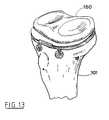
- a sliding element 150 of smaller dimensions than the upper area of the bearing plate 140is fitted over the bearing plate to bear on it from above.
- the sliding element 150is again of a suitable plastics material (e.g. UHMWPE) and has a recess 152 in its lower surface which accommodates the keel 61 with some amount of free play in the horizontal plane (i.e. in the medial/latero and anterio/posterior directions or a combination of both). However movement vertically is not possible. This free play has been shown as "a" in Fig. 11 and allows the sliding element 150 to float over the plate 140 surface by a limited amount, but still constrains it at the limits.
- the sliding element 150also includes a shaped upper surface with two, possibly spherically, dished upper recesses and a raised mid portion 153.
- the femur condyles"fit" into each of these dished parts and of course the contour of the dished surface must be adequately matched to the femur condyles.
- the femurmay not need a prosthetic replacement itself but this possibility is of course totally compatible with either the uni- or bi-condylar type of tibia replacement .
- the sliding element 150 in position on top of the bearing plate 140is shown in Figure 13.
- This Figurealso shows the sliding element in a position where the free play "a" (in Fig. 11) has allowed the sliding element 150 to move in order to leave a gap at the front left hand side (as depicted) of the tibial prosthesis.
- Fig. 14is a more preferred embodiment of the bi-condylar prosthesis, since only one hole 102 and one slot 102' need to be drilled and cut respectively in the sawn-off tibial bone.
- the elongate fixture element 131is clearly shown not central in this drawing and there are more splines on one side than on the other due to this relationship. In particular this is not merely due to the asymmetrical nature of the top of the tibia but also since a fixture which is offset from the plate 131 centre in the medial/latero direction will allow that the drilling and fitting of fixture element 131 will not interfere with the knee cap.
- the plate 130is inserted along with the fixture 131 and joint 138 into position on the prepared bone, having screw fixtures 120 (previously described) already fitted therein.
- a type of interference fitin the order of a few hundredths of a millimetre will occur thus giving a certain pretensioning of the bone surface and ensure a tight fit, which will lead to more rapid integration due to the minimal movement of the prosthesis that is possible.
- Slight vertical movement of the end of the plate 130i.e.
- the bearing plate 140with recessed edge shown at 142 so as to fit flush with the forward flange 133 of the plate 130. Similar recesses or flattened edges can be foreseen in addition or alone at the medial/latero edges of the plate 140 if this is felt necessary, although the keel fitting 60, 61 provides sufficient medial/latero stability in most cases such that such flanges on the plate 130 may not be necessary.
- the screws 121are fitted and the bearing plate 140 fitted into place over the keel fixture 60.
- the keelis consequently fixed in position with the aid of screw 64 and the sliding element 150 fitted.
- a bi-condylar knee joint prosthesis in accordance with the inventionis illustrated in Figs 15 - 19.
- the main difference between knee joint prostheses in accordance with the invention and the other prostheses described hereinaboveis that the elongate fixtures are designed to be oriented at an angle to the sagittal plane when the prosthesis has been implanted in the tibia, whilst the elongate fixtures in the previously described prostheses are designed to be oriented in parallel to the sagittal plane when implanted.
- the prosthesisthus for instance can be provided with splines or not be provided with splines or be provided with one assymmetrically located elongate fixture or two more or less symmetrically located elongate fixtures.
- bearing plate or sliding elements etcmay be similar to the parts used in the prostheses described previously.
- the prosthesis in the embodiment of the invention shown in Figs 15 - 17thus comprises a plate 230 provided with two tube-like, elongate fixtures 231 which are attached to the plate 230 by means of a connecting portion 238.
- the plate 230also is provided with bore-holes 253 for attachment screws 254 going through the connecting parts 238 and the fixtures 231. This location of the holes 253 will allow the bores to be countersunk (at 259) to an extent sufficient to ensure that the head of the screws 254 does not interfere with the upper surface of the plate 230.
- the screws 254are provided with a circumferential groove 255 and the fixtures 231 are provided with a longitudinal, threaded bore 256 extending from one end across one bore 253 to the other bore 253.
- the screws 254can be locked by means of lock screws 257 screwed into the bore 258 into engagement with the groove 255.
- the function of these bore-holes and attachment screwsis to lock the prosthesis against movements, primarily during the healing period.
- the line A - Aindicates the orientation of the sagittal plane when the plate 130 has been slid onto the tibia.
- the longitudinal direction of the fixturesform an angle ⁇ with the line A - A.
- the angle ⁇may vary between 5° and 45°, but preferably is between 15° and 35°, most preferably 20°-30°. In the embodiment illustrated, the angle ⁇ has been chosen to be 20°.
- One important advantageis that the access to the knee joint is greatly facilitated.
- the fact that the fixtures are to be obliquely oriented relative to the sagittal planemeans that all cutting and drilling operations can be performed from the ventral side of the proximal part of the tibia after cutting the anterior cruciate ligament without interfering with the patella since the patella and the ligamentum patellae easily can be pushed aside. Apart from this, the operation is essentially performed in the same way as the operation for implanting the prostheses according to Figs 11 - 14.
- the holes for the attachment screwscan be drilled into the bones through the holes 253 in the plate 230 and the screws 254, which preferably are self-tapping screws, can be screwed into the bone.
- the inner screw 254of course has to be locked by its respective lock screw 254 before the outer screw 254 is inserted.
- the prosthesiswill have a greater stability against movements during the healing period.
- the plate 230will be subjected to forces oriented in the sagittal plane during the normal articulation movements of the knee joint, since these movements mainly will be oriented in the sagittal plane.
- the fixtureswill however largely take up these forces due to their oblique orientation relative to the sagittal plane.
- the attachment screws 254, although useful in some applications,are not strictly necessary.
- the upper, cut surface of the tibiawill also be less disturbed and consequently have a better fit against the under side of the plate 230 since no fixtures (20, 120) for anchoring the plate are necessary. Another consequence is that the contact area between plate and tibia will be larger and that the risk that to much of the load on the plate is taken up by the fixtures is lessened. This in turn will enhance the osseointegration and lessen the risk for bone resorption.
- the further embodiment of the invention shown in Figs 18 and 19differs from the above embodiment in that only one elongate fixture is provided.
- the reference sign 230thus denotes the plate, 231 the elongate fixture, 233 the flange holding the bearing plate 240, 236 denotes splines on the elongate fixture, 201 the tibia and reference signs 61 and 64 the parts holding the bearing plate 240.
Landscapes
- Health & Medical Sciences (AREA)
- Orthopedic Medicine & Surgery (AREA)
- Life Sciences & Earth Sciences (AREA)
- Surgery (AREA)
- Animal Behavior & Ethology (AREA)
- Veterinary Medicine (AREA)
- Public Health (AREA)
- Engineering & Computer Science (AREA)
- Biomedical Technology (AREA)
- Heart & Thoracic Surgery (AREA)
- General Health & Medical Sciences (AREA)
- Neurology (AREA)
- Nuclear Medicine, Radiotherapy & Molecular Imaging (AREA)
- Medical Informatics (AREA)
- Molecular Biology (AREA)
- Vascular Medicine (AREA)
- Transplantation (AREA)
- Oral & Maxillofacial Surgery (AREA)
- Cardiology (AREA)
- Physical Education & Sports Medicine (AREA)
- Prostheses (AREA)
- Materials For Medical Uses (AREA)
Abstract
Description
Claims (20)
- A joint prosthesis for permanent anchorage in the bonetissue at the joint end of a first articulatory part of a joint, especially aknee joint, in the human body, said joint defining a predetermined mainarticulation plane, said joint prosthesis comprising a flat, plate-likeelement (230) having upper and lower major faces, the lower major faceadapted in use to engage with a complementary bone surface whichpresents the joint end or a part of the joint end of the first articulatorypart after resection of the original joint end or a part of the original jointend, and at least one elongate fixture (231) which is offset from andattached to the lower major face of the plate-like element so as to allowthe at least one elongate fixture in use to be located in healthy, relativelyintact bone, characterised in that the at least one elongate fixture is soarranged relative to the plate-like element that on anchorage of the jointprosthesis in the bone tissue at the joint end of the first articulatory partthe at least one elongate fixture is inclined at an angle relative to saidpredetermined main articulation plane.
- A joint prosthesis according to claim 1, characterised in thatthe or each elongate fixture is oriented along a plane forming an angle ofabout 15° to 45° with the predetermined main articulation plane.
- A joint prosthesis according to claim 1, characterised in thatthe or each elongate fixture is oriented along a plane forming an angle ofabout 15° to 35° with the predetermined main articulation plane.
- A joint prosthesis according to claim 1, characterised in thatthe or each elongate fixture is oriented along a plane forming an angle ofabout 20° to 30° with the predetermined main articulation plane.
- A joint prosthesis according to any of claims 1 to 4,characterised in that the at least one elongate fixture is provided withsplines or serrations (236) on the outer surface thereof.
- A joint prosthesis according to any of claims 1 to 5,characterised in that the lower major face of the plate-like elementpresents splines or serrations which extend in a direction substantiallyparallel to the axis of the at least one elongate fixture.
- A joint prosthesis according to any of the preceding claims,characterised in that the plate-like element is provided with one or moreapertures (253) which extend therethrough from the upper major face to thelower major face and are countersunk from the upper major face, whereinthe plate-like element and the at least one elongate fixture constitute amain body component part of the joint prosthesis and the joint prosthesisfurther comprises an anchoring screw (254) for each aperture, the or eachanchoring screw adapted in use to project through the associated apertureto anchor the main body component part to the joint end of the firstarticulatory part of the joint.
- A joint prosthesis according to claim 7 as appendant toclaim 6, characterised in that the or each aperture in the plate-likeelement is positioned so as to open in the lower major face of the plate-likeelement in an area which is free from splines or serrations.
- A joint prosthesis according to claim 7 or 8, characterised inthat the joint prosthesis comprises one or more self-tapping screw fixtureelements for implantation in the bone tissue at the joint end of the firstarticulatory part of the joint and that the or each anchoring screw has athreaded shank which is adapted in use to project through the associatedaperture and be received in a threaded bore presented by the screwfixture element or one of the screw fixture elements.
- A joint prosthesis according to claim 9, characterised in thatthe or each screw fixture element comprises two integral cylindricalportions of different diameter and is provided with a substantially flatupper face in which the threaded bore opens and an external screw threadfor fixing the screw fixture element in the bone tissue at the joint end ofthe first articulatory part of the joint.
- A joint prosthesis according to any of claims 1 to 6,characterised in that the or each elongate fixture is offset from andattached to the lower major face of the plate-like element by one or morerib elements (238), that the plate-like element, rib element or elementsand elongate fixture or fixtures constitute a main body component part ofthe joint prosthesis, that one or more apertures (253) are provided in themain body portion, the or each aperture extending downwardly from theupper major face of the plate-like element through one of the ribelements and the associated elongate fixture and that the joint prosthesisfurther comprises an anchoring screw (254) for each aperture, the or eachanchoring screw receivable in the associated aperture to anchor the main body component part to the bone tissue at the joint end of the firstarticulatory part of the joint.
- A joint prosthesis according to claim 11, characterised inthat the or each elongate fixture is provided with an axial screw threadedbore (256) and the joint prosthesis further comprises one or more lockscrews (257) for location in each axial screw threaded bore, the or eachlock screw adapted in use to act on one of the anchoring screws to lockthe anchoring screw in position.
- A joint prosthesis according to any of the preceding claims,characterised in that the joint prosthesis comprises one elongate fixturewhich is attached to the lower major face of the plate-like elementsubstantially in the mid-portion thereof.
- A joint prosthesis according to any of the preceding claims,characterised in that the plate-like element has a keel-fixture dependingfrom the upper major face thereof, said keel-fixture being approximatelycentrally positioned on the upper major face of the plate-like element.
- A joint prosthesis according to claim 14, characterised inthat the joint prosthesis comprises (i) a flat bearing element (240) havingupper and lower major faces and an aperture which extends therethroughfrom the upper major face to the lower major face to enable the bearingelement to fit over the keel-fixture and the lower major face of thebearing element to sit flat against the upper major face of the plate-likeelement, and (ii) a keel (61) having a rounded upper face and a recessedlower face and which is adapted in use to be fixedly attached to the keel-fixture to secure the bearing element in position on the plate-like elementagainst vertical displacement.
- A joint prosthesis according to claim 15, characterised inthat the joint prosthesis comprises a sliding element adapted in use to siton the upper major face of the bearing element, the sliding elementhaving a dished, for example spherically dished, upper face for co-operationwith the joint end of a second articulatory part of the joint.
- A joint prosthesis according to claim 16, characterised inthat the sliding element is made of ultra high molecular weightpolyethylene.
- A joint prosthesis according to claim 16 or 17, characterisedin that the sliding element is provided with a recess in its lower face forreceiving the keel, said recess being larger than the keel to allow alimited float of the sliding element across the bearing element uppermajor face.
- A joint prosthesis according to any of claims 15 to 18,characterised in that the bearing element is made from aCobalt/Chromium alloy, Cobalt/ Chromium/Molybdenum alloy or aceramics material.
- A joint prosthesis according to claim 19, characterised inthat the other elements of the joint prosthesis are made fromcommercially pure titanium.
Applications Claiming Priority (3)
| Application Number | Priority Date | Filing Date | Title |
|---|---|---|---|
| SE9201557 | 1992-05-18 | ||
| SE9201557ASE9201557D0 (en) | 1992-05-18 | 1992-05-18 | JOINT PROSTHESIS AND APPARATUS FOR PREPARING THE BONE PRIOR TO FITTING OF THE PROSTHESIS |
| PCT/SE1993/000427WO1993022990A1 (en) | 1992-05-18 | 1993-05-14 | Joint prosthesis and apparatus for preparing the bone prior to fitting of the prosthesis |
Publications (2)
| Publication Number | Publication Date |
|---|---|
| EP0642328A1 EP0642328A1 (en) | 1995-03-15 |
| EP0642328B1true EP0642328B1 (en) | 1998-12-30 |
Family
ID=20386270
Family Applications (1)
| Application Number | Title | Priority Date | Filing Date |
|---|---|---|---|
| EP93910530AExpired - LifetimeEP0642328B1 (en) | 1992-05-18 | 1993-05-14 | Joint prosthesis |
Country Status (15)
| Country | Link |
|---|---|
| EP (1) | EP0642328B1 (en) |
| JP (1) | JP3517413B2 (en) |
| AT (1) | ATE175094T1 (en) |
| AU (1) | AU680819B2 (en) |
| CA (1) | CA2136100C (en) |
| DE (1) | DE69322863T2 (en) |
| DK (1) | DK0642328T3 (en) |
| ES (1) | ES2127821T3 (en) |
| FI (1) | FI111803B (en) |
| GR (1) | GR3029808T3 (en) |
| IS (1) | IS4021A (en) |
| NO (1) | NO304482B1 (en) |
| NZ (1) | NZ252360A (en) |
| SE (1) | SE9201557D0 (en) |
| WO (1) | WO1993022990A1 (en) |
Cited By (13)
| Publication number | Priority date | Publication date | Assignee | Title |
|---|---|---|---|---|
| US8568486B2 (en) | 2010-07-24 | 2013-10-29 | Zimmer, Inc. | Asymmetric tibial components for a knee prosthesis |
| US8591594B2 (en) | 2010-09-10 | 2013-11-26 | Zimmer, Inc. | Motion facilitating tibial components for a knee prosthesis |
| US8628580B2 (en) | 2010-07-24 | 2014-01-14 | Zimmer, Inc. | Tibial prosthesis |
| US9308096B2 (en) | 2011-11-21 | 2016-04-12 | Zimmer, Inc. | Tibial baseplate with asymmetric placement of fixation structures |
| US9381090B2 (en) | 2010-07-24 | 2016-07-05 | Zimmer, Inc. | Asymmetric tibial components for a knee prosthesis |
| US10188530B2 (en) | 2010-12-17 | 2019-01-29 | Zimmer, Inc. | Provisional tibial prosthesis system |
| US10278827B2 (en) | 2015-09-21 | 2019-05-07 | Zimmer, Inc. | Prosthesis system including tibial bearing component |
| US10675153B2 (en) | 2017-03-10 | 2020-06-09 | Zimmer, Inc. | Tibial prosthesis with tibial bearing component securing feature |
| US10835380B2 (en) | 2018-04-30 | 2020-11-17 | Zimmer, Inc. | Posterior stabilized prosthesis system |
| US10898337B2 (en) | 2011-11-18 | 2021-01-26 | Zimmer, Inc. | Tibial bearing component for a knee prosthesis with improved articular characteristics |
| US11324599B2 (en) | 2017-05-12 | 2022-05-10 | Zimmer, Inc. | Femoral prostheses with upsizing and downsizing capabilities |
| US11324598B2 (en) | 2013-08-30 | 2022-05-10 | Zimmer, Inc. | Method for optimizing implant designs |
| US11426282B2 (en) | 2017-11-16 | 2022-08-30 | Zimmer, Inc. | Implants for adding joint inclination to a knee arthroplasty |
Families Citing this family (33)
| Publication number | Priority date | Publication date | Assignee | Title |
|---|---|---|---|---|
| FR2720627B1 (en)* | 1994-06-06 | 1996-10-31 | Jacques Hummer | Orthopedic fixation element. |
| US6695848B2 (en) | 1994-09-02 | 2004-02-24 | Hudson Surgical Design, Inc. | Methods for femoral and tibial resection |
| US5755808A (en)* | 1996-06-27 | 1998-05-26 | Joint Medical Products, Corporation | Connector plug for multi-component orthopedic implant |
| SE9804492D0 (en)* | 1998-12-22 | 1998-12-22 | Astra Ab | A prosthesis structure |
| US20050209703A1 (en)* | 1999-04-02 | 2005-09-22 | Fell Barry M | Surgically implantable prosthetic system |
| US7972337B2 (en) | 2005-12-28 | 2011-07-05 | Intrinsic Therapeutics, Inc. | Devices and methods for bone anchoring |
| US8323341B2 (en) | 2007-09-07 | 2012-12-04 | Intrinsic Therapeutics, Inc. | Impaction grafting for vertebral fusion |
| CA2425951C (en) | 1999-08-18 | 2008-09-16 | Intrinsic Therapeutics, Inc. | Devices and method for nucleus pulposus augmentation and retention |
| US7717961B2 (en) | 1999-08-18 | 2010-05-18 | Intrinsic Therapeutics, Inc. | Apparatus delivery in an intervertebral disc |
| GB2360457A (en)* | 2000-03-21 | 2001-09-26 | Biomet Merck Ltd | Knee prosthesis with keel |
| ATE334644T1 (en)* | 2000-10-11 | 2006-08-15 | Michael D Mason | INTEGRATED FUSION DEVICE |
| US8062377B2 (en) | 2001-03-05 | 2011-11-22 | Hudson Surgical Design, Inc. | Methods and apparatus for knee arthroplasty |
| ES2465090T3 (en) | 2002-12-20 | 2014-06-05 | Smith & Nephew, Inc. | High performance knee prostheses |
| US7033397B2 (en)* | 2003-02-03 | 2006-04-25 | Zimmer Technology, Inc. | Mobile bearing unicondylar tibial knee prosthesis |
| CA2542619C (en) | 2003-10-17 | 2011-10-11 | Smith & Nephew, Inc. | High flexion articular insert |
| US9814539B2 (en) | 2004-01-14 | 2017-11-14 | Puget Bioventures Llc | Methods and apparatus for conformable prosthetic implants |
| EP1574185B1 (en) | 2004-03-09 | 2012-05-23 | Zimmer Technology, Inc. | Tibial knee component with a mobile bearing |
| DE102004053075A1 (en)* | 2004-11-03 | 2006-05-11 | Nowakowski, Andrej, Dr. med. Dipl.-Ing.(FH) | Transversal-tibial plateau |
| US7572293B2 (en) | 2005-06-30 | 2009-08-11 | Depuy Products, Inc. | Tibial insert and associated surgical method |
| JP5406022B2 (en)* | 2006-06-12 | 2014-02-05 | スミス アンド ネフュー インコーポレーテッド | Tibial resection system, method and apparatus |
| US8114165B2 (en)* | 2006-06-22 | 2012-02-14 | Depuy Products, Inc. | Tibial insert and method for implanting the same |
| US8163027B2 (en) | 2006-06-22 | 2012-04-24 | Depuy Products, Inc. | Tibial insert having a reinforced keel |
| US8540778B2 (en) | 2006-06-22 | 2013-09-24 | DePuy Synthes Products, LLC | Tibial insert having multiple keels |
| US8764839B2 (en) | 2006-06-22 | 2014-07-01 | DePuy Synthes Products, LLC | Tibial insert having a keel including a bore formed therein |
| CA2656359C (en) | 2006-06-30 | 2016-11-22 | Smith & Nephew, Inc. | Anatomical motion hinged prosthesis |
| US9480511B2 (en) | 2009-12-17 | 2016-11-01 | Engage Medical Holdings, Llc | Blade fixation for ankle fusion and arthroplasty |
| GB201004068D0 (en) | 2010-03-11 | 2010-04-28 | Goodfellow John | Tibial prosthetic component for a partial or unicondylar meniscal bearing knee replacement,method of selecting such a tibial prosthetic component |
| BR112013009069A2 (en)* | 2010-10-14 | 2016-07-19 | Smith & Nephew Inc | patient-attached instrumentation and methods |
| EP2651341B1 (en)* | 2010-12-16 | 2017-01-04 | Engage Medical Holdings, LLC | Arthroplasty systems and methods |
| US9254130B2 (en) | 2011-11-01 | 2016-02-09 | Hyun Bae | Blade anchor systems for bone fusion |
| US10238382B2 (en) | 2012-03-26 | 2019-03-26 | Engage Medical Holdings, Llc | Blade anchor for foot and ankle |
| US10390955B2 (en) | 2016-09-22 | 2019-08-27 | Engage Medical Holdings, Llc | Bone implants |
| US10456272B2 (en) | 2017-03-03 | 2019-10-29 | Engage Uni Llc | Unicompartmental knee arthroplasty |
Family Cites Families (6)
| Publication number | Priority date | Publication date | Assignee | Title |
|---|---|---|---|---|
| SE450336B (en)* | 1984-11-28 | 1987-06-22 | Branemark Per Ingvar | LED PROTES FOR PERMANENT ANCHORING IN THE BONE TISSUE |
| CH671690A5 (en)* | 1987-05-15 | 1989-09-29 | Sulzer Ag | |
| SE468199B (en)* | 1988-04-11 | 1992-11-23 | Astra Ab | KNAELEDSPROTES |
| FR2630640B1 (en) | 1988-04-27 | 1994-04-08 | Lebeguec Pierre | PARTIAL KNEE PROSTHESIS DEVICE |
| SE466937B (en)* | 1989-04-25 | 1992-05-04 | Branemark Per Ingvar | ANCHORING DEVICE FOR BONE WOVEN APPLICABLE PROTESTES, SPEC LED MECHANISMS |
| US5171244A (en)* | 1990-01-08 | 1992-12-15 | Caspari Richard B | Methods and apparatus for arthroscopic prosthetic knee replacement |
- 1992
- 1992-05-18SESE9201557Apatent/SE9201557D0/enunknown
- 1993
- 1993-05-14DEDE69322863Tpatent/DE69322863T2/ennot_activeExpired - Fee Related
- 1993-05-14EPEP93910530Apatent/EP0642328B1/ennot_activeExpired - Lifetime
- 1993-05-14DKDK93910530Tpatent/DK0642328T3/enactive
- 1993-05-14NZNZ252360Apatent/NZ252360A/enunknown
- 1993-05-14ESES93910530Tpatent/ES2127821T3/ennot_activeExpired - Lifetime
- 1993-05-14WOPCT/SE1993/000427patent/WO1993022990A1/enactiveIP Right Grant
- 1993-05-14JPJP52013493Apatent/JP3517413B2/ennot_activeExpired - Fee Related
- 1993-05-14AUAU40990/93Apatent/AU680819B2/ennot_activeCeased
- 1993-05-14ATAT93910530Tpatent/ATE175094T1/ennot_activeIP Right Cessation
- 1993-05-14CACA002136100Apatent/CA2136100C/ennot_activeExpired - Fee Related
- 1993-05-18ISIS4021Apatent/IS4021A/enunknown
- 1994
- 1994-11-15NONO944367Apatent/NO304482B1/enunknown
- 1994-11-18FIFI945428Apatent/FI111803B/ennot_activeIP Right Cessation
- 1999
- 1999-03-26GRGR990400898Tpatent/GR3029808T3/enunknown
Cited By (38)
| Publication number | Priority date | Publication date | Assignee | Title |
|---|---|---|---|---|
| US9295557B2 (en) | 2010-07-24 | 2016-03-29 | Zimmer, Inc. | Asymmetric tibial components for a knee prosthesis |
| US8568486B2 (en) | 2010-07-24 | 2013-10-29 | Zimmer, Inc. | Asymmetric tibial components for a knee prosthesis |
| US10470889B2 (en) | 2010-07-24 | 2019-11-12 | Zimmer, Inc. | Asymmetric tibial components for a knee prosthesis |
| US8613775B2 (en) | 2010-07-24 | 2013-12-24 | Zimmer, Inc. | Asymmetric tibial components for a knee prosthesis |
| US8628580B2 (en) | 2010-07-24 | 2014-01-14 | Zimmer, Inc. | Tibial prosthesis |
| US8764840B2 (en) | 2010-07-24 | 2014-07-01 | Zimmer, Inc. | Tibial prosthesis |
| US9192480B2 (en) | 2010-07-24 | 2015-11-24 | Zimmer, Inc. | Asymmetric tibial components for a knee prosthesis |
| US9283082B2 (en) | 2010-07-24 | 2016-03-15 | Zimmer, Inc. | Methods related to seating of bearing component on tibial tray |
| US8574304B2 (en) | 2010-07-24 | 2013-11-05 | Zimmer, Inc. | Asymmetric tibial components for a knee prosthesis |
| US10195041B2 (en) | 2010-07-24 | 2019-02-05 | Zimmer, Inc. | Asymmetric tibial components for a knee prosthesis |
| US12239540B2 (en) | 2010-07-24 | 2025-03-04 | Zimmer, Inc. | Asymmetric tibial components for a knee prosthesis |
| US9381090B2 (en) | 2010-07-24 | 2016-07-05 | Zimmer, Inc. | Asymmetric tibial components for a knee prosthesis |
| US10543099B2 (en) | 2010-07-24 | 2020-01-28 | Zimmer, Inc. | Tibial prosthesis |
| US11224519B2 (en) | 2010-07-24 | 2022-01-18 | Zimmer, Inc. | Asymmetric tibial components for a knee prosthesis |
| US9763796B2 (en) | 2010-07-24 | 2017-09-19 | Zimmer, Inc. | Asymmetric tibial components for a knee prosthesis |
| US9763794B2 (en) | 2010-07-24 | 2017-09-19 | Zimmer, Inc. | Tibial prosthesis |
| US9861490B2 (en) | 2010-07-24 | 2018-01-09 | Zimmer, Inc. | Asymmetric tibial components for a knee prosthesis |
| US9918844B2 (en) | 2010-07-24 | 2018-03-20 | Zimmer, Inc. | Tibial prosthesis with a fixed bearing component |
| US11471288B2 (en) | 2010-09-10 | 2022-10-18 | Zimmer, Inc. | Motion facilitating tibial components for a knee prosthesis |
| US9763795B2 (en) | 2010-09-10 | 2017-09-19 | Zimmer, Inc. | Motion facilitating tibial components for a knee prosthesis |
| US9314343B2 (en) | 2010-09-10 | 2016-04-19 | Zimmer, Inc. | Motion facilitating tibial components for a knee prosthesis |
| US10413415B2 (en) | 2010-09-10 | 2019-09-17 | Zimmer, Inc. | Motion facilitating tibial components for a knee prosthesis |
| US8591594B2 (en) | 2010-09-10 | 2013-11-26 | Zimmer, Inc. | Motion facilitating tibial components for a knee prosthesis |
| US10188530B2 (en) | 2010-12-17 | 2019-01-29 | Zimmer, Inc. | Provisional tibial prosthesis system |
| US10898337B2 (en) | 2011-11-18 | 2021-01-26 | Zimmer, Inc. | Tibial bearing component for a knee prosthesis with improved articular characteristics |
| US12383407B2 (en) | 2011-11-18 | 2025-08-12 | Zimmer, Inc. | Tibial bearing component for a knee prosthesis with improved articular characteristics |
| US9308096B2 (en) | 2011-11-21 | 2016-04-12 | Zimmer, Inc. | Tibial baseplate with asymmetric placement of fixation structures |
| US9707089B2 (en) | 2011-11-21 | 2017-07-18 | Zimmer, Inc. | Tibial baseplate with asymmetric placement of fixation structures |
| US10265181B2 (en) | 2011-11-21 | 2019-04-23 | Zimmer, Inc. | Tibial baseplate with asymmetric placement of fixation structures |
| US11324598B2 (en) | 2013-08-30 | 2022-05-10 | Zimmer, Inc. | Method for optimizing implant designs |
| US11160659B2 (en) | 2015-09-21 | 2021-11-02 | Zimmer, Inc. | Prosthesis system including tibial bearing component |
| US10278827B2 (en) | 2015-09-21 | 2019-05-07 | Zimmer, Inc. | Prosthesis system including tibial bearing component |
| US10675153B2 (en) | 2017-03-10 | 2020-06-09 | Zimmer, Inc. | Tibial prosthesis with tibial bearing component securing feature |
| US11547571B2 (en) | 2017-03-10 | 2023-01-10 | Zimmer, Inc. | Tibial prosthesis with tibial bearing component securing feature |
| US11324599B2 (en) | 2017-05-12 | 2022-05-10 | Zimmer, Inc. | Femoral prostheses with upsizing and downsizing capabilities |
| US11426282B2 (en) | 2017-11-16 | 2022-08-30 | Zimmer, Inc. | Implants for adding joint inclination to a knee arthroplasty |
| US11911279B2 (en) | 2018-04-30 | 2024-02-27 | Zimmer, Inc. | Posterior stabilized prosthesis system |
| US10835380B2 (en) | 2018-04-30 | 2020-11-17 | Zimmer, Inc. | Posterior stabilized prosthesis system |
Also Published As
| Publication number | Publication date |
|---|---|
| NZ252360A (en) | 1997-03-24 |
| NO304482B1 (en) | 1998-12-28 |
| WO1993022990A1 (en) | 1993-11-25 |
| SE9201557D0 (en) | 1992-05-18 |
| NO944367L (en) | 1994-11-15 |
| CA2136100C (en) | 2002-11-26 |
| AU4099093A (en) | 1993-12-13 |
| ES2127821T3 (en) | 1999-05-01 |
| GR3029808T3 (en) | 1999-06-30 |
| AU680819B2 (en) | 1997-08-14 |
| FI111803B (en) | 2003-09-30 |
| FI945428A0 (en) | 1994-11-18 |
| DK0642328T3 (en) | 1999-08-30 |
| EP0642328A1 (en) | 1995-03-15 |
| JPH07506745A (en) | 1995-07-27 |
| IS4021A (en) | 1993-11-19 |
| JP3517413B2 (en) | 2004-04-12 |
| DE69322863T2 (en) | 1999-07-01 |
| CA2136100A1 (en) | 1993-11-25 |
| NO944367D0 (en) | 1994-11-15 |
| ATE175094T1 (en) | 1999-01-15 |
| DE69322863D1 (en) | 1999-02-11 |
| FI945428L (en) | 1994-11-18 |
Similar Documents
| Publication | Publication Date | Title |
|---|---|---|
| EP0642328B1 (en) | Joint prosthesis | |
| US6102954A (en) | Joint prosthesis and apparatus for preparing the bone prior to fitting of the prosthesis | |
| EP1480582B1 (en) | Patello-femoral joint replacement | |
| JP4610427B2 (en) | Tibial resection instrument | |
| US4822362A (en) | Process and apparatus for tibial plateau compenent | |
| CA2484522C (en) | Femoral components for knee arthroplasty | |
| CA1298436C (en) | Knee prosthesis | |
| EP0510103B1 (en) | Prosthesis | |
| US7615081B2 (en) | Femoral components for knee arthroplasty | |
| US5250050A (en) | Apparatus for knee prosthesis | |
| US5683469A (en) | Tibial trial prosthesis and bone preparation system | |
| EP1574184B1 (en) | Tibial implant with a through post | |
| US4904269A (en) | Hip joint prosthesis | |
| US20060142870A1 (en) | Modular total ankle prosthesis apparatuses, systems and methods, and systems and methods for bone resection and prosthetic implantation | |
| US20070135924A1 (en) | Joint replacement prosthesis, joint replacement mounting stud and method | |
| CA2887742C (en) | Rotary mill | |
| US10568645B2 (en) | Rotary mill | |
| AU2124701A (en) | Tibial resection instrument |
Legal Events
| Date | Code | Title | Description |
|---|---|---|---|
| PUAI | Public reference made under article 153(3) epc to a published international application that has entered the european phase | Free format text:ORIGINAL CODE: 0009012 | |
| 17P | Request for examination filed | Effective date:19941027 | |
| AK | Designated contracting states | Kind code of ref document:A1 Designated state(s):AT BE CH DE DK ES FR GB GR IE IT LI LU MC NL PT SE | |
| 17Q | First examination report despatched | Effective date:19970515 | |
| GRAG | Despatch of communication of intention to grant | Free format text:ORIGINAL CODE: EPIDOS AGRA | |
| GRAG | Despatch of communication of intention to grant | Free format text:ORIGINAL CODE: EPIDOS AGRA | |
| GRAH | Despatch of communication of intention to grant a patent | Free format text:ORIGINAL CODE: EPIDOS IGRA | |
| GRAH | Despatch of communication of intention to grant a patent | Free format text:ORIGINAL CODE: EPIDOS IGRA | |
| GRAA | (expected) grant | Free format text:ORIGINAL CODE: 0009210 | |
| AK | Designated contracting states | Kind code of ref document:B1 Designated state(s):AT BE CH DE DK ES FR GB GR IE IT LI LU MC NL PT SE | |
| REF | Corresponds to: | Ref document number:175094 Country of ref document:AT Date of ref document:19990115 Kind code of ref document:T | |
| REG | Reference to a national code | Ref country code:CH Ref legal event code:EP | |
| ITF | It: translation for a ep patent filed | ||
| REG | Reference to a national code | Ref country code:IE Ref legal event code:FG4D | |
| REF | Corresponds to: | Ref document number:69322863 Country of ref document:DE Date of ref document:19990211 | |
| ET | Fr: translation filed | ||
| REG | Reference to a national code | Ref country code:PT Ref legal event code:SC4A Free format text:AVAILABILITY OF NATIONAL TRANSLATION Effective date:19990127 | |
| REG | Reference to a national code | Ref country code:ES Ref legal event code:FG2A Ref document number:2127821 Country of ref document:ES Kind code of ref document:T3 | |
| PG25 | Lapsed in a contracting state [announced via postgrant information from national office to epo] | Ref country code:LU Free format text:LAPSE BECAUSE OF NON-PAYMENT OF DUE FEES Effective date:19990514 | |
| REG | Reference to a national code | Ref country code:DK Ref legal event code:T3 | |
| PLBE | No opposition filed within time limit | Free format text:ORIGINAL CODE: 0009261 | |
| STAA | Information on the status of an ep patent application or granted ep patent | Free format text:STATUS: NO OPPOSITION FILED WITHIN TIME LIMIT | |
| PG25 | Lapsed in a contracting state [announced via postgrant information from national office to epo] | Ref country code:MC Free format text:LAPSE BECAUSE OF NON-PAYMENT OF DUE FEES Effective date:19991130 | |
| 26N | No opposition filed | ||
| REG | Reference to a national code | Ref country code:GB Ref legal event code:IF02 | |
| PGFP | Annual fee paid to national office [announced via postgrant information from national office to epo] | Ref country code:NL Payment date:20090506 Year of fee payment:17 Ref country code:IE Payment date:20090501 Year of fee payment:17 Ref country code:ES Payment date:20090511 Year of fee payment:17 Ref country code:DK Payment date:20090507 Year of fee payment:17 | |
| PGFP | Annual fee paid to national office [announced via postgrant information from national office to epo] | Ref country code:SE Payment date:20090518 Year of fee payment:17 Ref country code:PT Payment date:20090505 Year of fee payment:17 Ref country code:IT Payment date:20090513 Year of fee payment:17 Ref country code:FR Payment date:20090506 Year of fee payment:17 Ref country code:DE Payment date:20090506 Year of fee payment:17 Ref country code:AT Payment date:20090506 Year of fee payment:17 | |
| PGFP | Annual fee paid to national office [announced via postgrant information from national office to epo] | Ref country code:BE Payment date:20090506 Year of fee payment:17 | |
| PGFP | Annual fee paid to national office [announced via postgrant information from national office to epo] | Ref country code:CH Payment date:20090506 Year of fee payment:17 | |
| PGFP | Annual fee paid to national office [announced via postgrant information from national office to epo] | Ref country code:GR Payment date:20090526 Year of fee payment:17 Ref country code:GB Payment date:20090511 Year of fee payment:17 | |
| REG | Reference to a national code | Ref country code:PT Ref legal event code:MM4A Free format text:LAPSE DUE TO NON-PAYMENT OF FEES Effective date:20101115 | |
| BERE | Be: lapsed | Owner name:*ASTRA A.B. Effective date:20100531 | |
| REG | Reference to a national code | Ref country code:NL Ref legal event code:V1 Effective date:20101201 | |
| REG | Reference to a national code | Ref country code:CH Ref legal event code:PL | |
| REG | Reference to a national code | Ref country code:DK Ref legal event code:EBP | |
| GBPC | Gb: european patent ceased through non-payment of renewal fee | Effective date:20100514 | |
| PG25 | Lapsed in a contracting state [announced via postgrant information from national office to epo] | Ref country code:AT Free format text:LAPSE BECAUSE OF NON-PAYMENT OF DUE FEES Effective date:20100514 | |
| EUG | Se: european patent has lapsed | ||
| REG | Reference to a national code | Ref country code:FR Ref legal event code:ST Effective date:20110131 | |
| PG25 | Lapsed in a contracting state [announced via postgrant information from national office to epo] | Ref country code:PT Free format text:LAPSE BECAUSE OF NON-PAYMENT OF DUE FEES Effective date:20101115 Ref country code:LI Free format text:LAPSE BECAUSE OF NON-PAYMENT OF DUE FEES Effective date:20100531 Ref country code:CH Free format text:LAPSE BECAUSE OF NON-PAYMENT OF DUE FEES Effective date:20100531 | |
| REG | Reference to a national code | Ref country code:IE Ref legal event code:MM4A | |
| PG25 | Lapsed in a contracting state [announced via postgrant information from national office to epo] | Ref country code:SE Free format text:LAPSE BECAUSE OF NON-PAYMENT OF DUE FEES Effective date:20100515 Ref country code:GR Free format text:LAPSE BECAUSE OF NON-PAYMENT OF DUE FEES Effective date:20101202 Ref country code:NL Free format text:LAPSE BECAUSE OF NON-PAYMENT OF DUE FEES Effective date:20101201 Ref country code:IT Free format text:LAPSE BECAUSE OF NON-PAYMENT OF DUE FEES Effective date:20100514 Ref country code:BE Free format text:LAPSE BECAUSE OF NON-PAYMENT OF DUE FEES Effective date:20100531 | |
| PG25 | Lapsed in a contracting state [announced via postgrant information from national office to epo] | Ref country code:IE Free format text:LAPSE BECAUSE OF NON-PAYMENT OF DUE FEES Effective date:20100514 Ref country code:DK Free format text:LAPSE BECAUSE OF NON-PAYMENT OF DUE FEES Effective date:20100531 Ref country code:DE Free format text:LAPSE BECAUSE OF NON-PAYMENT OF DUE FEES Effective date:20101201 | |
| PG25 | Lapsed in a contracting state [announced via postgrant information from national office to epo] | Ref country code:FR Free format text:LAPSE BECAUSE OF NON-PAYMENT OF DUE FEES Effective date:20100531 | |
| REG | Reference to a national code | Ref country code:ES Ref legal event code:FD2A Effective date:20110715 | |
| PG25 | Lapsed in a contracting state [announced via postgrant information from national office to epo] | Ref country code:ES Free format text:LAPSE BECAUSE OF NON-PAYMENT OF DUE FEES Effective date:20110705 Ref country code:GB Free format text:LAPSE BECAUSE OF NON-PAYMENT OF DUE FEES Effective date:20100514 | |
| PG25 | Lapsed in a contracting state [announced via postgrant information from national office to epo] | Ref country code:ES Free format text:LAPSE BECAUSE OF NON-PAYMENT OF DUE FEES Effective date:20100515 |