EP0639953B1 - Ultrasound catheter for removing obstructions from tubular anatomical structures such as blood vessels - Google Patents
Ultrasound catheter for removing obstructions from tubular anatomical structures such as blood vesselsDownload PDFInfo
- Publication number
- EP0639953B1 EP0639953B1EP93911045AEP93911045AEP0639953B1EP 0639953 B1EP0639953 B1EP 0639953B1EP 93911045 AEP93911045 AEP 93911045AEP 93911045 AEP93911045 AEP 93911045AEP 0639953 B1EP0639953 B1EP 0639953B1
- Authority
- EP
- European Patent Office
- Prior art keywords
- transmission member
- proximal
- ultrasound transmission
- catheter
- ultrasound
- Prior art date
- Legal status (The legal status is an assumption and is not a legal conclusion. Google has not performed a legal analysis and makes no representation as to the accuracy of the status listed.)
- Expired - Lifetime
Links
- 238000002604ultrasonographyMethods0.000titleclaimsabstractdescription181
- 210000004204blood vesselAnatomy0.000titleclaimsabstractdescription11
- 210000003484anatomyAnatomy0.000titleclaimsdescription7
- 230000005540biological transmissionEffects0.000claimsabstractdescription117
- 239000011248coating agentSubstances0.000claimsdescription24
- 238000000576coating methodMethods0.000claimsdescription24
- 230000001419dependent effectEffects0.000claimsdescription3
- 230000006835compressionEffects0.000claims16
- 238000007906compressionMethods0.000claims16
- 239000000463materialSubstances0.000abstractdescription15
- 229910001092metal group alloyInorganic materials0.000abstractdescription9
- 230000002829reductive effectEffects0.000abstractdescription6
- 230000003321amplificationEffects0.000abstractdescription4
- 238000003199nucleic acid amplification methodMethods0.000abstractdescription4
- 229910001000nickel titaniumInorganic materials0.000abstractdescription3
- HZEWFHLRYVTOIW-UHFFFAOYSA-N[Ti].[Ni]Chemical compound[Ti].[Ni]HZEWFHLRYVTOIW-UHFFFAOYSA-N0.000abstract1
- 239000012530fluidSubstances0.000description24
- 229920003023plasticPolymers0.000description15
- 239000004033plasticSubstances0.000description15
- 239000000853adhesiveSubstances0.000description12
- 230000001070adhesive effectEffects0.000description12
- 239000007788liquidSubstances0.000description11
- 239000002826coolantSubstances0.000description9
- 230000007704transitionEffects0.000description8
- 238000003780insertionMethods0.000description7
- 230000037431insertionEffects0.000description7
- 238000001802infusionMethods0.000description6
- -1polytetrafluoroethylenePolymers0.000description6
- 210000004351coronary vesselAnatomy0.000description5
- 229910000734martensiteInorganic materials0.000description5
- 239000002184metalSubstances0.000description5
- 229910052751metalInorganic materials0.000description5
- 229910001285shape-memory alloyInorganic materials0.000description5
- 238000013016dampingMethods0.000description4
- 230000000694effectsEffects0.000description4
- 238000000034methodMethods0.000description4
- 238000012986modificationMethods0.000description4
- 230000004048modificationEffects0.000description4
- 230000036961partial effectEffects0.000description4
- 229920001343polytetrafluoroethylenePolymers0.000description4
- 238000007789sealingMethods0.000description4
- PXHVJJICTQNCMI-UHFFFAOYSA-NNickelChemical compound[Ni]PXHVJJICTQNCMI-UHFFFAOYSA-N0.000description3
- 230000000712assemblyEffects0.000description3
- 238000000429assemblyMethods0.000description3
- 229910001566austeniteInorganic materials0.000description3
- 239000007769metal materialSubstances0.000description3
- 239000002904solventSubstances0.000description3
- 239000004677NylonSubstances0.000description2
- 239000004698PolyethyleneSubstances0.000description2
- 238000002679ablationMethods0.000description2
- 239000004676acrylonitrile butadiene styreneSubstances0.000description2
- TZCXTZWJZNENPQ-UHFFFAOYSA-Lbarium sulfateChemical compound[Ba+2].[O-]S([O-])(=O)=OTZCXTZWJZNENPQ-UHFFFAOYSA-L0.000description2
- 239000000919ceramicSubstances0.000description2
- 238000010276constructionMethods0.000description2
- 239000005038ethylene vinyl acetateSubstances0.000description2
- 238000000605extractionMethods0.000description2
- 230000006870functionEffects0.000description2
- 229910052759nickelInorganic materials0.000description2
- 229920001778nylonPolymers0.000description2
- 230000000704physical effectEffects0.000description2
- 229920000573polyethylenePolymers0.000description2
- 239000004810polytetrafluoroethyleneSubstances0.000description2
- 238000003466weldingMethods0.000description2
- 208000037260Atherosclerotic PlaqueDiseases0.000description1
- 235000003801Castanea crenataNutrition0.000description1
- 244000209117Castanea crenataSpecies0.000description1
- 229920001651CyanoacrylatePolymers0.000description1
- 229920001875EbonitePolymers0.000description1
- 241001465754MetazoaSpecies0.000description1
- MWCLLHOVUTZFKS-UHFFFAOYSA-NMethyl cyanoacrylateChemical compoundCOC(=O)C(=C)C#NMWCLLHOVUTZFKS-UHFFFAOYSA-N0.000description1
- 241001645095ParisisSpecies0.000description1
- 239000004743PolypropyleneSubstances0.000description1
- 239000004809TeflonSubstances0.000description1
- 229920006362Teflon®Polymers0.000description1
- XECAHXYUAAWDEL-UHFFFAOYSA-Nacrylonitrile butadiene styreneChemical compoundC=CC=C.C=CC#N.C=CC1=CC=CC=C1XECAHXYUAAWDEL-UHFFFAOYSA-N0.000description1
- 229920000122acrylonitrile butadiene styrenePolymers0.000description1
- 229910045601alloyInorganic materials0.000description1
- 239000000956alloySubstances0.000description1
- 210000002376aorta thoracicAnatomy0.000description1
- 238000013459approachMethods0.000description1
- 210000001367arteryAnatomy0.000description1
- 230000006399behaviorEffects0.000description1
- 229910052797bismuthInorganic materials0.000description1
- JCXGWMGPZLAOME-UHFFFAOYSA-Nbismuth atomChemical compound[Bi]JCXGWMGPZLAOME-UHFFFAOYSA-N0.000description1
- 210000004369bloodAnatomy0.000description1
- 239000008280bloodSubstances0.000description1
- DQXBYHZEEUGOBF-UHFFFAOYSA-Nbut-3-enoic acid;etheneChemical compoundC=C.OC(=O)CC=CDQXBYHZEEUGOBF-UHFFFAOYSA-N0.000description1
- 238000004891communicationMethods0.000description1
- 239000002131composite materialSubstances0.000description1
- 230000003247decreasing effectEffects0.000description1
- 239000006185dispersionSubstances0.000description1
- 239000003814drugSubstances0.000description1
- 229920001971elastomerPolymers0.000description1
- 210000001105femoral arteryAnatomy0.000description1
- 239000000945fillerSubstances0.000description1
- 239000011888foilSubstances0.000description1
- 230000002262irrigationEffects0.000description1
- 238000003973irrigationMethods0.000description1
- 230000000670limiting effectEffects0.000description1
- 238000004021metal weldingMethods0.000description1
- 239000000203mixtureSubstances0.000description1
- 239000002991molded plasticSubstances0.000description1
- 229920003052natural elastomerPolymers0.000description1
- 229920001194natural rubberPolymers0.000description1
- 230000000414obstructive effectEffects0.000description1
- 238000013021overheatingMethods0.000description1
- 210000005259peripheral bloodAnatomy0.000description1
- 239000011886peripheral bloodSubstances0.000description1
- 229920001200poly(ethylene-vinyl acetate)Polymers0.000description1
- 239000002861polymer materialSubstances0.000description1
- 229920000098polyolefinPolymers0.000description1
- 229920001155polypropylenePolymers0.000description1
- 229920002635polyurethanePolymers0.000description1
- 239000004814polyurethaneSubstances0.000description1
- 239000005060rubberSubstances0.000description1
- 239000010935stainless steelSubstances0.000description1
- 229910001220stainless steelInorganic materials0.000description1
- 229920003051synthetic elastomerPolymers0.000description1
- 239000005061synthetic rubberSubstances0.000description1
- 229920001169thermoplasticPolymers0.000description1
- 239000004416thermosoftening plasticSubstances0.000description1
- 230000009424thromboembolic effectEffects0.000description1
- 239000010936titaniumSubstances0.000description1
- 210000005166vasculatureAnatomy0.000description1
Images


Classifications
- A—HUMAN NECESSITIES
- A61—MEDICAL OR VETERINARY SCIENCE; HYGIENE
- A61B—DIAGNOSIS; SURGERY; IDENTIFICATION
- A61B17/00—Surgical instruments, devices or methods
- A61B17/22—Implements for squeezing-off ulcers or the like on inner organs of the body; Implements for scraping-out cavities of body organs, e.g. bones; for invasive removal or destruction of calculus using mechanical vibrations; for removing obstructions in blood vessels, not otherwise provided for
- A61B17/22004—Implements for squeezing-off ulcers or the like on inner organs of the body; Implements for scraping-out cavities of body organs, e.g. bones; for invasive removal or destruction of calculus using mechanical vibrations; for removing obstructions in blood vessels, not otherwise provided for using mechanical vibrations, e.g. ultrasonic shock waves
- A61B17/22012—Implements for squeezing-off ulcers or the like on inner organs of the body; Implements for scraping-out cavities of body organs, e.g. bones; for invasive removal or destruction of calculus using mechanical vibrations; for removing obstructions in blood vessels, not otherwise provided for using mechanical vibrations, e.g. ultrasonic shock waves in direct contact with, or very close to, the obstruction or concrement
- A—HUMAN NECESSITIES
- A61—MEDICAL OR VETERINARY SCIENCE; HYGIENE
- A61B—DIAGNOSIS; SURGERY; IDENTIFICATION
- A61B17/00—Surgical instruments, devices or methods
- A61B17/32—Surgical cutting instruments
- A61B17/3205—Excision instruments
- A61B17/3207—Atherectomy devices working by cutting or abrading; Similar devices specially adapted for non-vascular obstructions
- A61B17/320758—Atherectomy devices working by cutting or abrading; Similar devices specially adapted for non-vascular obstructions with a rotating cutting instrument, e.g. motor driven
- A—HUMAN NECESSITIES
- A61—MEDICAL OR VETERINARY SCIENCE; HYGIENE
- A61B—DIAGNOSIS; SURGERY; IDENTIFICATION
- A61B17/00—Surgical instruments, devices or methods
- A61B2017/00017—Electrical control of surgical instruments
- A61B2017/00022—Sensing or detecting at the treatment site
- A61B2017/00084—Temperature
- A61B2017/00101—Temperature using an array of thermosensors
- A—HUMAN NECESSITIES
- A61—MEDICAL OR VETERINARY SCIENCE; HYGIENE
- A61B—DIAGNOSIS; SURGERY; IDENTIFICATION
- A61B17/00—Surgical instruments, devices or methods
- A61B2017/00477—Coupling
- A—HUMAN NECESSITIES
- A61—MEDICAL OR VETERINARY SCIENCE; HYGIENE
- A61B—DIAGNOSIS; SURGERY; IDENTIFICATION
- A61B17/00—Surgical instruments, devices or methods
- A61B2017/00831—Material properties
- A61B2017/0084—Material properties low friction
- A61B2017/00849—Material properties low friction with respect to tissue, e.g. hollow organs
- A—HUMAN NECESSITIES
- A61—MEDICAL OR VETERINARY SCIENCE; HYGIENE
- A61B—DIAGNOSIS; SURGERY; IDENTIFICATION
- A61B17/00—Surgical instruments, devices or methods
- A61B2017/00831—Material properties
- A61B2017/00867—Material properties shape memory effect
- A—HUMAN NECESSITIES
- A61—MEDICAL OR VETERINARY SCIENCE; HYGIENE
- A61B—DIAGNOSIS; SURGERY; IDENTIFICATION
- A61B17/00—Surgical instruments, devices or methods
- A61B17/22—Implements for squeezing-off ulcers or the like on inner organs of the body; Implements for scraping-out cavities of body organs, e.g. bones; for invasive removal or destruction of calculus using mechanical vibrations; for removing obstructions in blood vessels, not otherwise provided for
- A61B17/22004—Implements for squeezing-off ulcers or the like on inner organs of the body; Implements for scraping-out cavities of body organs, e.g. bones; for invasive removal or destruction of calculus using mechanical vibrations; for removing obstructions in blood vessels, not otherwise provided for using mechanical vibrations, e.g. ultrasonic shock waves
- A61B17/22012—Implements for squeezing-off ulcers or the like on inner organs of the body; Implements for scraping-out cavities of body organs, e.g. bones; for invasive removal or destruction of calculus using mechanical vibrations; for removing obstructions in blood vessels, not otherwise provided for using mechanical vibrations, e.g. ultrasonic shock waves in direct contact with, or very close to, the obstruction or concrement
- A61B2017/22014—Implements for squeezing-off ulcers or the like on inner organs of the body; Implements for scraping-out cavities of body organs, e.g. bones; for invasive removal or destruction of calculus using mechanical vibrations; for removing obstructions in blood vessels, not otherwise provided for using mechanical vibrations, e.g. ultrasonic shock waves in direct contact with, or very close to, the obstruction or concrement the ultrasound transducer being outside patient's body; with an ultrasound transmission member; with a wave guide; with a vibrated guide wire
- A61B2017/22015—Implements for squeezing-off ulcers or the like on inner organs of the body; Implements for scraping-out cavities of body organs, e.g. bones; for invasive removal or destruction of calculus using mechanical vibrations; for removing obstructions in blood vessels, not otherwise provided for using mechanical vibrations, e.g. ultrasonic shock waves in direct contact with, or very close to, the obstruction or concrement the ultrasound transducer being outside patient's body; with an ultrasound transmission member; with a wave guide; with a vibrated guide wire with details of the transmission member
- A61B2017/22018—Implements for squeezing-off ulcers or the like on inner organs of the body; Implements for scraping-out cavities of body organs, e.g. bones; for invasive removal or destruction of calculus using mechanical vibrations; for removing obstructions in blood vessels, not otherwise provided for using mechanical vibrations, e.g. ultrasonic shock waves in direct contact with, or very close to, the obstruction or concrement the ultrasound transducer being outside patient's body; with an ultrasound transmission member; with a wave guide; with a vibrated guide wire with details of the transmission member segmented along its length
- A—HUMAN NECESSITIES
- A61—MEDICAL OR VETERINARY SCIENCE; HYGIENE
- A61B—DIAGNOSIS; SURGERY; IDENTIFICATION
- A61B17/00—Surgical instruments, devices or methods
- A61B17/22—Implements for squeezing-off ulcers or the like on inner organs of the body; Implements for scraping-out cavities of body organs, e.g. bones; for invasive removal or destruction of calculus using mechanical vibrations; for removing obstructions in blood vessels, not otherwise provided for
- A61B2017/22038—Implements for squeezing-off ulcers or the like on inner organs of the body; Implements for scraping-out cavities of body organs, e.g. bones; for invasive removal or destruction of calculus using mechanical vibrations; for removing obstructions in blood vessels, not otherwise provided for with a guide wire
- A61B2017/22039—Implements for squeezing-off ulcers or the like on inner organs of the body; Implements for scraping-out cavities of body organs, e.g. bones; for invasive removal or destruction of calculus using mechanical vibrations; for removing obstructions in blood vessels, not otherwise provided for with a guide wire eccentric
- A—HUMAN NECESSITIES
- A61—MEDICAL OR VETERINARY SCIENCE; HYGIENE
- A61B—DIAGNOSIS; SURGERY; IDENTIFICATION
- A61B17/00—Surgical instruments, devices or methods
- A61B17/22—Implements for squeezing-off ulcers or the like on inner organs of the body; Implements for scraping-out cavities of body organs, e.g. bones; for invasive removal or destruction of calculus using mechanical vibrations; for removing obstructions in blood vessels, not otherwise provided for
- A61B2017/22038—Implements for squeezing-off ulcers or the like on inner organs of the body; Implements for scraping-out cavities of body organs, e.g. bones; for invasive removal or destruction of calculus using mechanical vibrations; for removing obstructions in blood vessels, not otherwise provided for with a guide wire
- A61B2017/22041—Implements for squeezing-off ulcers or the like on inner organs of the body; Implements for scraping-out cavities of body organs, e.g. bones; for invasive removal or destruction of calculus using mechanical vibrations; for removing obstructions in blood vessels, not otherwise provided for with a guide wire outside the catheter
- A—HUMAN NECESSITIES
- A61—MEDICAL OR VETERINARY SCIENCE; HYGIENE
- A61B—DIAGNOSIS; SURGERY; IDENTIFICATION
- A61B17/00—Surgical instruments, devices or methods
- A61B17/32—Surgical cutting instruments
- A61B17/320068—Surgical cutting instruments using mechanical vibrations, e.g. ultrasonic
- A61B2017/320072—Working tips with special features, e.g. extending parts
- A61B2017/320073—Working tips with special features, e.g. extending parts probe
- A—HUMAN NECESSITIES
- A61—MEDICAL OR VETERINARY SCIENCE; HYGIENE
- A61B—DIAGNOSIS; SURGERY; IDENTIFICATION
- A61B17/00—Surgical instruments, devices or methods
- A61B17/32—Surgical cutting instruments
- A61B17/320068—Surgical cutting instruments using mechanical vibrations, e.g. ultrasonic
- A61B2017/320088—Surgical cutting instruments using mechanical vibrations, e.g. ultrasonic with acoustic insulation, e.g. elements for damping vibrations between horn and surrounding sheath
- A—HUMAN NECESSITIES
- A61—MEDICAL OR VETERINARY SCIENCE; HYGIENE
- A61B—DIAGNOSIS; SURGERY; IDENTIFICATION
- A61B18/00—Surgical instruments, devices or methods for transferring non-mechanical forms of energy to or from the body
- A61B2018/00005—Cooling or heating of the probe or tissue immediately surrounding the probe
- A61B2018/00011—Cooling or heating of the probe or tissue immediately surrounding the probe with fluids
- A61B2018/00029—Cooling or heating of the probe or tissue immediately surrounding the probe with fluids open
- A—HUMAN NECESSITIES
- A61—MEDICAL OR VETERINARY SCIENCE; HYGIENE
- A61B—DIAGNOSIS; SURGERY; IDENTIFICATION
- A61B2217/00—General characteristics of surgical instruments
- A61B2217/002—Auxiliary appliance
- A61B2217/005—Auxiliary appliance with suction drainage system
- A—HUMAN NECESSITIES
- A61—MEDICAL OR VETERINARY SCIENCE; HYGIENE
- A61B—DIAGNOSIS; SURGERY; IDENTIFICATION
- A61B2217/00—General characteristics of surgical instruments
- A61B2217/002—Auxiliary appliance
- A61B2217/007—Auxiliary appliance with irrigation system
- A—HUMAN NECESSITIES
- A61—MEDICAL OR VETERINARY SCIENCE; HYGIENE
- A61B—DIAGNOSIS; SURGERY; IDENTIFICATION
- A61B90/00—Instruments, implements or accessories specially adapted for surgery or diagnosis and not covered by any of the groups A61B1/00 - A61B50/00, e.g. for luxation treatment or for protecting wound edges
- A61B90/39—Markers, e.g. radio-opaque or breast lesions markers
- A—HUMAN NECESSITIES
- A61—MEDICAL OR VETERINARY SCIENCE; HYGIENE
- A61F—FILTERS IMPLANTABLE INTO BLOOD VESSELS; PROSTHESES; DEVICES PROVIDING PATENCY TO, OR PREVENTING COLLAPSING OF, TUBULAR STRUCTURES OF THE BODY, e.g. STENTS; ORTHOPAEDIC, NURSING OR CONTRACEPTIVE DEVICES; FOMENTATION; TREATMENT OR PROTECTION OF EYES OR EARS; BANDAGES, DRESSINGS OR ABSORBENT PADS; FIRST-AID KITS
- A61F2/00—Filters implantable into blood vessels; Prostheses, i.e. artificial substitutes or replacements for parts of the body; Appliances for connecting them with the body; Devices providing patency to, or preventing collapsing of, tubular structures of the body, e.g. stents
- A61F2/02—Prostheses implantable into the body
- A61F2/30—Joints
- A61F2002/30001—Additional features of subject-matter classified in A61F2/28, A61F2/30 and subgroups thereof
- A61F2002/30003—Material related properties of the prosthesis or of a coating on the prosthesis
- A61F2002/3006—Properties of materials and coating materials
- A61F2002/30092—Properties of materials and coating materials using shape memory or superelastic materials, e.g. nitinol
- A—HUMAN NECESSITIES
- A61—MEDICAL OR VETERINARY SCIENCE; HYGIENE
- A61F—FILTERS IMPLANTABLE INTO BLOOD VESSELS; PROSTHESES; DEVICES PROVIDING PATENCY TO, OR PREVENTING COLLAPSING OF, TUBULAR STRUCTURES OF THE BODY, e.g. STENTS; ORTHOPAEDIC, NURSING OR CONTRACEPTIVE DEVICES; FOMENTATION; TREATMENT OR PROTECTION OF EYES OR EARS; BANDAGES, DRESSINGS OR ABSORBENT PADS; FIRST-AID KITS
- A61F2210/00—Particular material properties of prostheses classified in groups A61F2/00 - A61F2/26 or A61F2/82 or A61F9/00 or A61F11/00 or subgroups thereof
- A61F2210/0014—Particular material properties of prostheses classified in groups A61F2/00 - A61F2/26 or A61F2/82 or A61F9/00 or A61F11/00 or subgroups thereof using shape memory or superelastic materials, e.g. nitinol
- A61F2210/0019—Particular material properties of prostheses classified in groups A61F2/00 - A61F2/26 or A61F2/82 or A61F9/00 or A61F11/00 or subgroups thereof using shape memory or superelastic materials, e.g. nitinol operated at only one temperature whilst inside or touching the human body, e.g. constrained in a non-operative shape during surgery, another temperature only occurring before the operation
- A—HUMAN NECESSITIES
- A61—MEDICAL OR VETERINARY SCIENCE; HYGIENE
- A61F—FILTERS IMPLANTABLE INTO BLOOD VESSELS; PROSTHESES; DEVICES PROVIDING PATENCY TO, OR PREVENTING COLLAPSING OF, TUBULAR STRUCTURES OF THE BODY, e.g. STENTS; ORTHOPAEDIC, NURSING OR CONTRACEPTIVE DEVICES; FOMENTATION; TREATMENT OR PROTECTION OF EYES OR EARS; BANDAGES, DRESSINGS OR ABSORBENT PADS; FIRST-AID KITS
- A61F2210/00—Particular material properties of prostheses classified in groups A61F2/00 - A61F2/26 or A61F2/82 or A61F9/00 or A61F11/00 or subgroups thereof
- A61F2210/0014—Particular material properties of prostheses classified in groups A61F2/00 - A61F2/26 or A61F2/82 or A61F9/00 or A61F11/00 or subgroups thereof using shape memory or superelastic materials, e.g. nitinol
- A61F2210/0023—Particular material properties of prostheses classified in groups A61F2/00 - A61F2/26 or A61F2/82 or A61F9/00 or A61F11/00 or subgroups thereof using shape memory or superelastic materials, e.g. nitinol operated at different temperatures whilst inside or touching the human body, heated or cooled by external energy source or cold supply
- A61F2210/0042—Particular material properties of prostheses classified in groups A61F2/00 - A61F2/26 or A61F2/82 or A61F9/00 or A61F11/00 or subgroups thereof using shape memory or superelastic materials, e.g. nitinol operated at different temperatures whilst inside or touching the human body, heated or cooled by external energy source or cold supply using a fluid, e.g. circulating
- A—HUMAN NECESSITIES
- A61—MEDICAL OR VETERINARY SCIENCE; HYGIENE
- A61M—DEVICES FOR INTRODUCING MEDIA INTO, OR ONTO, THE BODY; DEVICES FOR TRANSDUCING BODY MEDIA OR FOR TAKING MEDIA FROM THE BODY; DEVICES FOR PRODUCING OR ENDING SLEEP OR STUPOR
- A61M25/00—Catheters; Hollow probes
- A61M25/01—Introducing, guiding, advancing, emplacing or holding catheters
- A61M2025/0183—Rapid exchange or monorail catheters
- A—HUMAN NECESSITIES
- A61—MEDICAL OR VETERINARY SCIENCE; HYGIENE
- A61M—DEVICES FOR INTRODUCING MEDIA INTO, OR ONTO, THE BODY; DEVICES FOR TRANSDUCING BODY MEDIA OR FOR TAKING MEDIA FROM THE BODY; DEVICES FOR PRODUCING OR ENDING SLEEP OR STUPOR
- A61M3/00—Medical syringes, e.g. enemata; Irrigators
- A61M3/02—Enemata; Irrigators
- A61M3/0279—Cannula; Nozzles; Tips; their connection means
Definitions
- the present inventionpertains to medical equipment and more particularly an ultrasonic catheter for ablating obstructions within tubular anatomical structures such as blood vessels.
- ultrasonic deviceshave heretofore been proposed for use in ablating or removing obstructive material from blood vessels.
- Examples of ultrasonic ablation devices in related apparatus purported to be useable in removing obstructions from blood vesselsinclude those described in United States Patent Nos.
- Ultrasound transmitting cathetershave been utilized to successfully ablate various types of obstructions from blood vessels of humans and animals. Particular success has been observed in ablation of atherosclerotic plaque or thromboembolic obstructions from peripheral blood vessels such as the femoral arteries. Successful applications of ultrasonic energy to smaller blood vessels, such as the coronary arteries, necessitates the use of ultrasound transmitting catheters which are sufficiently small and flexible to permit transluminal advancement of such catheter through the tortuous vasculature of the aortic arch and coronary tree. Accordingly, the safety and efficacy of removing obstructions from coronary arteries by way of ultrasound is largely dependent upon the size and flexibility of the ultrasound transmitting catheter(s) employed.
- the present inventionprovides catheters as in claims 1 and 2.
- the pre-ambles of these claimsare based on WO-A-90/1300.
- an ultrasound catheter devicecomprising an elongate flexible catheter body having at least one lumen extending longitudinally therethrough.
- An elongate ultrasound transmission memberextends through the catheter body and is connected, at its distal end, to a distal head. The entire distal head, or a portion thereof, may protrude out of and beyond the distal end of the catheter body. The distal head is secured or affixed to the catheter body.
- the ultrasound transmission member extending longitudinally through the catheteris formed of one or more superelastic materials, such as certain superelastic metal alloys, which exhibit superelastic properties within the range of temperatures undergone by the ultrasound transmission member during operation of the device.
- the ultrasound transmission memberhas a proximal portion of a first cross-sectional dimension or diameter and a distal portion of a second cross-sectional dimension or diameter less than said first cross-sectional dimension or diameter.
- Such lessening of the cross-sectional dimension or diameter of the distal portion of the ultrasound transmission memberresults in more flexibility and less rigidity of the ultrasound transmission member within such region thereof. Additionally, such lessening of the cross-sectional dimension or diameter of the distal portion of the ultrasound transmission member results in an amplification of ultrasound transmitted through such transmission member.
- a guidewire passage lumenextends longitudinally through the catheter to permit the catheter to be utilized in accordance with over-the-wire (OTW) insertion techniques.
- OWover-the-wire
- a guidewire guide or memberextends laterally outboard of the catheter in at least one position thereon.
- Such guidewire guide or support memberis provided with at least one guidewire passage aperture extending longitudinally therethrough to permit a guidewire to be passed therethrough, thereby permitting the ultrasound catheter to be utilized in accordance with monorail guidewire insertion techniques.
- a distal guidewire lumenextending longitudinally through only a distal portion of the catheter.
- Such distal guidewire passage lumencomprises an elongate tube or passageway having a distal end and a proximal end.
- the distal end of the elongate tube or passagewayopens through a distal end aperture and the proximal end of the elongate tube or passageway opens through a guidewire entry/re-entry aperture formed at a point in the sidewall of the catheter.
- a guidewiremay be proximally or distally advanced through said distal guidewire lumen within the distal portion of the catheter body while a remaining proximal portion of the guidewire resides outside of and next to the catheter body.
- proximal end connector assemblieswhich operate to connect the proximal end of an ultrasound transmission catheter to an ultrasound transducer.
- the proximal end connector assembliespreferably comprise generally tubular members having at least one longitudinal bore through which the ultrasound transmission member of the catheter may extend and at least one connector apparatus for connecting the ultrasound transmission member to an attendant ultrasound transducer.
- the sonic connectorcomprises a compressible gripping ferrule which may be tightened to grip and firmly hold the ultrasound transmission member in place to provide a damping effect to prevent undesirable transverse movement.
- the sonic connectorcomprises a plurality of compressible plugs which are also tightened to grip and firmly hold the ultrasound transmission member to achieve the required damping effect, as well as to secure the ultrasound transmission member to the sonic connector.
- the sonic connectorcomprises both a plurality of compressible plugs and a gripping ferrule.
- a polymeric coatingmay be applied to the various connections between the ultrasound transmission member and the sonic connector, either in conjunction with the gripping ferrule and/or the compressible plugs or independent of the ferrule and plugs, to secure these connections.
- proximal end connector assemblies of catheters of the present inventionmay preferably be provided with one or more fluid infusion sidearms for infusing coolant liquid or other fluid through the bore of the proximal connector and through a lumen of the catheter body.
- a guidewire passage sidearmmay be positioned on the proximal connector assembly to permit insertion and/or extraction of a guidewire through the proximal connector assembly and through the body of the catheter.
- One or more guidewire diverting memberssuch as an angled tubular member, may be positioned within the proximal connector assembly to divert a proximally advancing guidewire out of a guidewire sidearm positioned thereon.
- said ultrasound transmission memberhas a friction-reducing coating or outer jacket formed thereon.
- Such friction reducing coating or outer jacketmay comprise a layer of low friction polymeric material such as polytetrafluoroethylene (ptfe) (teflonTM Dupont, Inc., Wilmington, Delaware) or polyethylene.
- ptfepolytetrafluoroethylene
- Such friction reducing coating or jacketmay be disposed over the entire outer surface of the ultrasound transmission member or may be confined to a specific region or regions thereof.
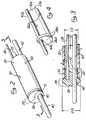
- Figure 1is a perspective view of a first embodiment of an over-the-wire ultrasound catheter of the present invention.
- Figure 2is partial enlarged perspective view of the distal end of a first embodiment of an over-the-wire ultrasound catheter of the present invention.
- Figure 2ais a partial cut-away perspective view of an ultrasound transmission member positionable in an ultrasound catheter and having a friction reducing coating or jacket disposed thereon.
- Figure 3is a longitudinal sectional view through Line 3-3 of Figure 2.
- Figure 4is an enlarged perspective view of the distal portion of an embodiment of a monorail ultrasound catheter of the present invention.
- Figure 5is a perspective view of the distal portion of an embodiment of an ultrasound catheter of the present invention having a region of enlarged diameter and a partial guidewire lumen running through a distal portion of the catheter body.
- Figure 5ais a perspective view of the distal portion of an embodiment of an ultrasound catheter of the present invention having a partial guidewire lumen running through a distal portion of the catheter body.
- Figure 6is a longitudinal sectional view of the embodiment of the ultrasound catheter shown in Figure 5.
- Figure 6ais an exploded view of a distal tip of the ultrasound catheter embodiments shown in Figures 5 and 5a.
- Figure 6bis an enlarged view of the distal end of the longitudinal sectional view of Figure 6.
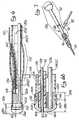
- Figure 7is a perspective view of a proximal end connector end apparatus positionable on the proximal end of an ultrasound catheter for connecting the catheter to an ultrasound transducer.
- Figure 8is a perspective view of an alternative proximal end connector assembly positionable on the proximal end of an ultrasound catheter having an internal guidewire lumen for attaching the ultrasound catheter to an ultrasound transducer.
- Figure 9is a longitudinal sectional view of the proximal end connector assembly shown in Figure 5.
- Figure 10is a perspective view of the guidewire diverter apparatus and a first embodiment of a sonic connector positioned within the proximal end connector assembly shown in Figures 5 and 6.
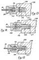
- Figure 11is an enlarged perspective view of a second embodiment of a sonic connector positioned within the proximal end connector assembly of Figure 10.
- Figure 12is a cross-sectional view of the sonic connector of Figure 11 taken along Line 12-12 in Figure 11.
- Figure 13is an enlarged perspective view of a third embodiment of a sonic connector positioned within the proximal end connector assembly of Figure 10.
- Figure 14is an enlarged perspective view of a fourth embodiment of a sonic connector positioned within the proximal end connector assembly of Figure 10.
- Figure 15is an enlarged perspective view of a fifth embodiment of a sonic connector positioned within the proximal end connector assembly of Figure 10.
- the ultrasound catheters of the present inventioninclude both "over-the-wire” configurations and “monorail” configuration.
- the term “over-the-wire”shall refer to an ultrasound catheter which has a guidewire passage lumen formed within the body of the catheter such that a flexible guidewire may be advanced through the body of the catheter and out of a guidewire passage aperture formed in the distal end of the catheter.
- the term “monorail”shall refer to an ultrasound catheter which has a guidewire supporting structure at or near the distal tip of the catheter and extending laterally outboard of the outer surface of the catheter body such that a flexible guidewire may reside next to the catheter body with the distal end of such guidewire extending through and/or being held by the guidewire supporting structure formed on or near the distal end of the catheter body.
- Figure 1is a perspective showing of an over-the-wire ultrasound catheter 10 of the present invention having a proximal end connector assembly 12 mounted on the proximal end thereof.
- An ultrasound transducer 14is connected to the proximal end of the proximal connector assembly 12.
- An ultrasound generator 16having a foot actuated on/off switch 18 is operatively connected to the ultrasound generator 14 so as to send ultrasonic energy through the ultrasound catheter 10, when desired.
- an over-the-wire ultrasound catheter 10 of the present inventionis shown in Figures 2 and 3.
- one embodiment of an over-the-wire ultrasound catheter 10 of the present inventioncomprises a flexible tubular catheter body 20 having a hollow lumen 22 extending longitudinally therethrough.
- This over-the-wire catheter bodypreferably has an outside diameter of 0.5 mm - 5.0 mm.
- the outer diameter of the catheter body 20be 0.25 mm - 2.5 mm.
- a monorail ultrasound catheter 10a of the present inventioncomprises a flexible tubular catheter body 20a having a hollow lumen 22a extending longitudinally therethrough.
- the outside diameter of the catheter body 20a of the monorail catheter 10abe 0.5 mm - 5.0 mm.
- the outer diameter of the catheter bodybe 0.25 mm - 2.0 mm and it is further specifically preferable that the width of the distal head 26a be, at its widest point, no greater than 3.0 mm such that the entire distal head 26a and the catheter body 20a may be inserted into an anatomical passageway of approximately 3.0 mm diameter, (e.g. the coronary artery).
- an ultrasound transmission member 24 or wave guideextends longitudinally through the lumen 22 of the catheter body 20 to transmit ultrasonic energy from an ultrasound transducer 14 connected to the proximal end of the catheter 10 to the distal end thereof.
- a distal head 26is mounted on the distal end of the ultrasound transmission member 24.
- the distal head 26comprises generally round, conical, or disc-shaped distal portion 28 and a reduced diameter neck or proximal portion 30.
- the outer diameter OD of the proximal portion 30 of the distal head 26is approximately the same as or slightly less than the inner diameter ID of the catheter lumen 22 such that the proximal portion 30 of the distal head 26 may be inserted into the distal end of the lumen 22, to a point where the distal tip of the catheter body 20 abuts against the proximal aspect of the distal portion 28 of the distal head 26, as shown.
- the ultrasound transmission member 24may be formed of any material capable of effectively transmitting the ultrasonic energy from the ultrasound transducer 14 to the distal end of the catheter body 20, including but not necessary limited to metal, plastic, hard rubber, ceramic and/or composites thereof.
- all or a portion of the ultrasound transmission member 24may be formed of one or more materials which exhibit superelasticity. Such material(s) should preferably exhibit superelasticity consistently within the range of temperatures normally encountered by the ultrasound transmission member 24 during operation of the device 10.
- all or part of the ultrasound transmission member 24may be formed of one or more metal alloys known as "shape memory alloys".
- one presently preferred superelastic metal alloy of which the ultrasound transmission member 24 may be formedis a nickel-titanium alloy wire made up of 55.8 weight percent nickel (NiTi containing 55.8% weight % Ni balance Ti). Such material is commercially available as TinelTM Wire from Raychem Corporation, Menlo Park, California.
- the ultrasound transmission member 24may be tapered, narrowed or otherwise reduced in cross-sectional dimension within a distal portion of the catheter so as to decrease the rigidity of the ultrasound transmission member 24 within such distal portion of the device and also to cause amplification of the ultrasound transmitted to the distal head 26.
- such tapering or narrowing of the ultrasound transmission memberdivides the ultrasound transmission member into a proximal portion 24p and a distal portion 24d.
- An angular tapered or narrowing region 154embodies the transition zone between the larger proximal portion 24p and the smaller distal portion 24d.
- the distal portion 24d of the ultrasound transmission memberis of smaller cross-sectional diameter and less mass, it is more flexible and less rigid than the proximal portion 24p thereof.
- Such configuration of the ultrasound member 24enables the relatively large sized proximal portion 24p to transmit more ultrasonic energy than if the entire length of the ultrasound transmission member 24 were to be of the relatively small cross-sectional size of the distal portion 24d thereof. Additionally, such decrease in the cross-sectional size of the distal portion 24d of the ultrasound transmission member 24 results in an amplification of the ultrasound transmitted through such distal portion 24d thereof.
- the proximal portion 24p of the ultrasound transmission memberis rendered capable of transmitting a greater amount of ultrasonic energy to the distal end of the catheter than would otherwise be possible, while the reduced cross-sectional size of the distal portion of the ultrasound transmission member 24 additionally serves to amplify the ultrasound reaching the distal head 26 of the device.
- the taper 154 of the ultrasound transmission member 24bbe positioned at the distal end of the bulge or enlarged region 152 so as to result in that portion of the catheter lying distal to the distal end of the enlarged region 152 being more flexible and less rigid than the remainder of said catheter, due to the decreased diameter of the ultrasound transmission member 24d extending through such portion.
- the tapered region 154 of the ultrasound transmission member 24may be formed at any point desired such that portion of the catheter lying distal to the tapered region 154 will, as a result, exhibit less rigidity and greater flexibility than the remainder of the catheter body.
- An optional improvement to the ultrasound transmission member 24 of any ultrasound transmitting cathetercomprises the disposition of a low friction coating or jacket 25 on the outer surface of all or a portion of the ultrasound transmission member 24.
- the low friction coating or jacket 25may be disposed on the outer surface of the ultrasound transmission member 24 so as to completely cover the ultrasound transmission member 24 along its entire length, or along a discrete region or regions thereof.
- Such coating or jacket 25may comprise a layer of low friction polymer material such as polytetrafluoroethylene (ptfe) (teflonTM Dupont, Inc., Wilmington, Delaware) or other plastic materials such as polyethylene.
- the coating or jacket 25may be applied as a liquid and subsequently allowed to cure or harden on the surface of the ultrasound transmission member 24.
- the coating jacket 25may be in the form of an elongate tube slideably disposable over the outer surface of the ultrasound transmission member 24.
- Such coating or jacket 25serves to prevent or diminish friction between the outer surface of the ultrasound transmission member 24 and the adjacent structures of the catheter 10 or proximal end connector assembly 12 through which the ultrasound transmission member 24 extends.
- the distal head 26is firmly bonded, attached, or connected to the catheter body 20 such that the distal head is prevented from undergoing longitudinal or transverse movement separate from or relative to the catheter body.
- Such non-moveable affixation of the distal head 26 to the catheter bodyprevents longitudinal or transverse movement of the distal head 26 apart from the catheter body 20.
- affixation of the distal head to the catheter bodyincreases the conveyance of ultrasound energy into the distal portion of the catheter body 20, thereby resulting in enhanced cavitation effects created by the distal portion of the catheter body.
- Such bonding connection or attachment of the distal head 26 to the catheter body 20may be accomplished by any suitable means.
- One means of attaching the distal head 26 to the catheter body 20is through the use of adhesive 32.
- the adhesive 32is applied to the proximal portion 30 of the distal head 26 prior to insertion thereof into the distal end of the lumen 22 of the catheter body 20.
- the adhesive 32may comprise any suitable adhesive, such as cyanoacrylate (eg. LoctiteTM, Loctite Corp., Ontario, CANADA. or Dron AlphaTM, Borden, Inc., Columbus, Ohio) or polyurethane (eg. DymaxTM, Dymax Engineering Adhesive, Torrington, CT.) to firmly bond and attach the distal head 26 to the catheter body 20.
- the distal head 26may be formed of any suitable rigid material such as metal or plastic. In devices wherein the distal head is formed of plastic, the surrounding plastic catheter body 20 may be thoroughly welded, heat sealed or solvent welded to the plastic distal head 26, in accordance with the types of plastics employed.
- various mechanical or frictional connectorssuch as screw threads, lugs or other surface modifications formed on the proximal portion 30 of the distal head 26, may be utilized to hold the distal head 26 in a fixed position relative to the catheter body 20.
- corresponding grooves, detents or surface modificationsmay also be formed in the surrounding inner wall of the catheter body 20 so as to cooperate with any such threads, lugs or other surface modifications formed on the opposing surface of the distal head 26.
- Such threads, lugs or other surface modificationswill be configured and constructed so as to mechanically or frictionally hold the distal head 26 in fixed position relative to the catheter body 20.
- the distal head 26is preferably formed of radiodense material so as to be easily discernabie by radiographic means. Accordingly, the distal head 26 may preferably be formed of metal or, alternatively, may be formed of plastic, ceramic or rubber materials, optionally having one or more radiodense markers affixed thereto or formed therein.
- the distal head 26may be molded of plastic such as acrylonitrile-butadiene-styrene (ABS) and one or more metallic foil strips or other radio opaque markers may be affixed to such plastic distal head 26 in order to impart sufficient radiodensity to permit the distal head 26 to be readily located by radiographic means.
- ABSacrylonitrile-butadiene-styrene
- a quantity of radiodense fillersuch as powdered bismuth or BaSO 4 may be disposed within the plastic or other non-metallic material of which the distal head 26 is formed so as to impart enhanced radiodensity to the distal head 26.
- An optional guidewire passage aperture 40may extend longitudinally through the distal head 26.
- Such guidewire passage aperture 40may be formed through the distal head at a location inboard of the catheter body 20 such that a guidewire 42 may be advanced through a lumen 22 of the catheter body and through guidewire passage aperture 40.
- Such embodiments of the ultrasound catheter 10 wherein the guidewire 42 passes through a lumen formed within the catheter body 20 and out of the catheter passage aperture 40constitute an "over-the-wire" embodiment of the invention.
- the distal head 26amay be formed such that a portion of the distal head extends laterally outboard of the outer surface of the catheter body 20a and the guidewire passage aperture 40a may be, likewise, positioned outboard of the outer surface of the catheter body 20a thereby forming a guidewire alongside the catheter body 20a and through the guidewire passage aperture 40a.
- the guidewire 42ais passed outboard of the outer surface of the catheter body 20a and through the catheter passage aperture 40a are referred to sometimes herein as "monorail" embodiments.
- the ultrasound catheter of the present inventionmay also be formed in embodiments which constitute combinations or hybrids of such over-the-wire and monorail embodiments, as shown in Figures 5, 5a and 6.
- such embodiments of the inventioncomprise an ultrasound catheter having a guidewire passage lumen formed through a distal portion of the catheter body only, with a guidewire entry/re-entry aperture 160 being formed through a sidewall of the catheter to permit passage of the guidewire 42 from the distal guidewire lumen of the catheter to a position outside the catheter body.
- the catheter body 20bmay be provided with a distal guidewire passage tube 156 positioned within the inner bore or lumen 22b of the catheter body 20b and extending from a guidewire re-entry aperture 160 to the guidewire passage aperture 40b formed in the distal head 26b of the device.
- the proximal end of a pre-inserted guidewiremay be inserted into the distal end of the catheter body 20b through guidewire passage aperture 40b and subsequently advanced in a proximal direction through the guidewire lumen 158 to a point where the proximal end of the guidewire 42 emerges out of guidewire entry/re-entry aperture 160.
- the proximal portion of the guidewire 42may extend and/or reside adjacent the outer surface of the proximal portion of the catheter body 20b as shown.
- the catheter body 20b and the guidewire 42may then be distally and/or proximally repositioned, relative to one another, during the procedure.
- the guidewire 42may be fully withdrawn and extracted by pulling the guidewire in a proximal direction such that the distal tip of the guidewire is pulled out of the guidewire entry/re-entry aperture 160 and the guidewire 42 is subsequently fully withdrawn out of the body, leaving only the ultrasound catheter in place.
- distal head 26is shown in the embodiments of Figures 5, 5a, 6, 6a and 6b.
- the distal head 26b, 26cis secured to the distal end of the catheter body 20b, 20c by way of an annular ring member 150 and a quantity of adhesive ADH.
- this embodiment of the distal head 26bcomprises a distal portion 28b and a reduced diameter proximal portion 30b which is insertable into the distal end of the lumen 22b of the catheter body 20b.
- the distal portion 28b of the distal head 26bhas a grooved detent or annular shoulder 148 formed therein.
- the proximal portion 30b of the distal head 26bis inserted into the distal end of the lumen 20b of the catheter body and may be secured thereto by way of a quantity of adhesive.
- An annular ring member 150is then passed in a proximal direction over the catheter body 20b and advanced to a point where the annular ring member 150 abuts against shoulder 148.
- a quantity of adhesive ADHis then applied to secure the annular ring member 150 around the distal tip of the catheter body 20b and the part of the distal portion 28b of the distal head 26b.
- the adhesive ADHmay be tapered or smoothed to form a constant angular transition from the distal portion 28b of the distal head 26b to the outer surface of the catheter body 20b as shown.
- the distal head 26b and annular ring member 150may be formed of any suitable rigid material such as metal or plastic. In embodiments where metal materials are employed, metal bonding or metal welding may be utilized as an alternative to or in addition to the use of adhesives for bonding the assembly to the distal end of the catheter body 20b. In embodiments wherein the distal head 26b and annular ring member 150 are formed of plastic, thermal welding, heat fusing or solvent welding techniques may be used as an alternative or in addition to the use of adhesives for such purpose.
- the outer diameter of the annular ring member 150be approximately the same as the largest outer diameter of the extreme distal portion 28b of the distal head 26b such that a smooth transition is formed from the distal head 26b to the outer surface of the catheter body 20b.
- one or more fluid outflow aperture(s) 50are formed at or near the distal end of the catheter body 20 to permit fluid to flow out of a lumen 22 of the catheter 10.
- the provision of such fluid outflow aperture(s) 50 near the distal end of the catheter 10facilitates continual or intermittent passage of coolant liquid into the proximal end of the lumen 22, distally through the lumen 22, and out of fluid outflow aperture(s) 50.
- the lumen 22 of the catheter 10 into which the fluid outflow aperture(s) communicateswill be the same lumen wherein the ultrasound transmission member 24 is located such that coolant liquid may be infused into the proximal end of such lumen 22, distally therethrough and out of fluid outflow aperture(s) 50 in a manner that will bathe and cool the body of the ultrasound transmission member 24, thereby preventing the ultrasound transmission member 24 from overheating during use.
- one or more fluid outflow aperture(s) 51may be formed through the distal head 26 to permit fluid to flow directly out of the distal end of the catheter 10.
- a guidewire aperture 40 formed through the distal head 26such guidewire aperture may be slightly larger than the outer diameter of the guidewire 42 to be passed therethrough so as to permit fluid to be infused through the guidewire lumen and to pass out of the guidewire aperture 40, even when a guidewire 42 is extending therethrough.
- the guidewire aperture 40may, in some embodiments, preclude the necessity for and/or perform the function of a separate dedicated fluid outflow aperture 51 extending through the distal head 26.
- one or more separate lumens having separate outflow apertures formed at or near the distal tip of the cathetermay be formed for infusion of oxygenated perfusate, medicaments or other fluids into the blood vessel or other anatomical structure in which the catheter is positioned.
- proximal end connector apparatus 12may be positioned on the proximal end of the catheter body to facilitate operative connection of the ultrasound transmission member 24 to an ultrasound transducer 14 and ultrasound generation device 16. Examples of embodiments of such proximal end connector apparatus 12 are shown in Figures 7-10.
- Figure 7shows a relatively simple proximal end connector apparatus 12a configured for use in connection with catheters which do not incorporate internal guidewire passage lumens.
- Figure 8shows a more complex proximal end connector 12b configured for use in connection with catheters having internal guidewire passage lumens.
- the embodiment of the proximal end connector 12a shown in Figure 7comprises a rear portion 92 and a mid-portion 90.
- a gripping member 96 formed on the proximal end of the mid-portion 90operates to attach the proximal end connector 12a to the proximal end of the catheter 20.
- the mid-portion 90comprises an elongate tubular body 80 having a tubular fluid infusion sidearm 82 extending outwardly therefrom to permit infusion of coolant fluid or other liquid into the inner lumen 81 of the proximal end connector 12a.
- the more complex embodiment of the proximal end connector 12b shown in Figure 8comprises the same rear portion 92 and mid-portion 90 as the simpler embodiment 12a shown in Figure 7.
- the more complex embodiment 12b of Figure 8further comprises a frontal portion 88 which is configured and constructed to facilitate insertion and/or extraction of a guidewire 42 through a lumen or passageway formed internally within the catheter 20.
- the proximal end connector apparatus 12comprises an elongate rigid body 80 having a hollow bore 81 extending longitudinally therethrough.
- the elongate body of the proximal end connector 12is actually constructed of a frontal portion 88, a mid-portion 90 and a rear portion 92.
- the frontal portion 88 of the elongate body 80is firmly connected to the proximal end of the catheter body 20 by way of a threaded gripping member 94.
- a sleeve 21 having an annular flange 23 formed on the proximal end thereofis positioned on the proximal end of the catheter body 20 to engage gripping member 94 as shown.
- the proximal end of the frontal portion 88is connected to the distal end of the mid-portion 90 of the elongate body 80 by way of a second gripping member 96. Accordingly, to facilitate such construction, threads 98, 100 are formed on the opposite ends of the frontal portion 88 of the elongate body 80.
- Threads 102are also formed on the proximal end of the mid-portion 90 of the elongate body 80 such that the mid-portion 90 may be threadably mounted within a correspondingly threaded bore formed in the distal end of the rear portion 92 of the elongate body 80.
- An O-ring 104is positioned at the bottom of the threaded bore formed in the distal end of the rear portion 92 such that, when the rear portion 92 is tightened over the threads 102 of the mid-portion 90, the proximal end 108 of the mid-portion 90 will abut against and compress O-ring 104 against ledge 105, thereby causing O-ring 104 to exert inward pressure against tube 110.
- Tube 110extends longitudinally through the hollow bore 81 within the rear portion 92 of the proximal connector apparatus 12.
- the ultrasound transmission member 24 or wave guideextends longitudinally through the entire catheter body 20 and through the proximal end connector 12.
- the ultrasound transmission member 24 or wave guideis inserted into and engaged by threaded proximal connector 112.
- Threaded proximal connector 112is positioned within a cylindrical recess 114 formed in the proximal end of the proximal connector apparatus 12.
- a suitable ultrasound transducer 14may be screwed onto and threadably connected to the threaded proximal connector 112 to accomplish passage of ultrasonic energy through the ultrasound transmission member 24 in a distal direction to the distal head 26 of the device.
- the extreme proximal end of the proximal connector 12is provided with a sonic connector assembly or apparatus configured to effect operative attachment of the proximal end of the ultrasound transmission member 24 to the horn of an ultrasound transducer 14.
- the sonic connector assembly or apparatusis preferably configured and constructed to permit passage of ultrasound energy through the ultrasound transmission member or wave guide 24 with minimal lateral side-to-side movement of the ultrasound transmission member 24 while, at the same time, permitting unrestricted longitudinal forward/backward vibration or movement of the ultrasound transmission member 24.
- a distal portion of the body of the threaded proximal connector 112is configured to receive therein a compressible gripping ferrule 116.
- Compressible gripping ferrule 116has a small central aperture formed therethrough through which the ultrasound transmission member 24 passes, as shown.
- a frontal member 118is threadably tightened within the frontal portion of the body of proximal connector member 112 so as to compress gripping ferrule 116, thereby causing gripping ferrule 116 to firmly grip and hold the ultrasound transmission member 24 in place within the body of the proximal connector member 112.
- the proximal connector member 112may then be compressed or crimped inwardly so as to be additionally crimp connected or crimp fit to the proximal end of the ultrasound transmission member 24, thereby providing further gripping and attachment of the sonic connector assembly to the proximal end of the ultrasound transmission member.
- a series of threadsare formed on the outer surface of the proximal connector member 112 to permit the distal end of an ultrasound transducer horn to be threadably screwed onto and releasably attached to the sonic connector assembly.
- the frontal member 118, gripping ferrule 116, and proximal connector member 112combine to form a sonic connector assembly to which the horn of an ultrasound transducer may be attached and through which the ultrasonic energy may be transmitted into the ultrasound transmission member, with the gripping ferrule 116 acting to dampen transverse movement of the ultrasound transmission member 24.
- a frontal member 218is positionable on the ultrasound transmission member 24, and has a stem 220 with threads 222 provided thereon for threadable engagement with threads 221 provided in an opening of a proximal connector 212.
- a plurality of compressible plugs 224are configured to fit within the opening of the proximal connector 212 perpendicular to the axis of the ultrasound transmission member 24. In the preferred embodiment, four compressible plugs 224 are provided, but it will be appreciated by those skilled in the art that any number of compressible plugs 224 may be distributed about the circumference of the ultrasound transmission member 24.
- the proximal connector 212is also positionable on the ultrasound transmission member 24 and also has a stem 214 with threads 216 provided thereon for threadable engagement with threads 217 provided on a cavity 226 of a horn 228 of the ultrasound transducer 14. Again, a plurality of compressible plugs 224 are configured to fit within the cavity 226 of the ultrasound transducer horn 228 perpendicular to the axis of the ultrasound transmission member 24. The proximal-most end of the ultrasound transmission member 24 terminates at the promixal-most end of the stem 214 within the cavity 226.
- the stem 214 and the ultrasound transmission member 24may be crimped as shown at 230 to provide a more stable connection between the sonic connector assembly and the ultrasound transmission member 24.
- the frontal member 218 and the proximal connector 212are preferably made from stainless steel.
- the compressible plugs 224are preferably disposed along the threads 216, 217, 221 and 222 so that when the frontal member 218 is threadably screwed onto the proximal connector 212 and the proximal connector 212 is in turn threadably screwed onto the ultrasound transducer horn 228, the threads 216, 217, 221 and 222 exert an inward force against the plugs 224 provided thereat, thereby forcing the plugs 224 against the ultrasound transmission member 24 to provide a firm grip to minimize transverse movement of the ultrasound transmission member 24.
- the compressible plugs 224are preferably made from any compliant material such as plastic, nylon, teflon, ABS, polypropylene, polyolefins, natural and synthetic rubbers and ethylene vinyl acetate (EVA).
- the compliance of the plugs 224also secures the threaded connection between the frontal member 218 and the proximal connector 212 so that this connection does not become loosened, which would otherwise cause the ultrasound transmission member 24 to become disengaged.
- the plugs 224may be provided at the threads 221 and 222 only, or at the threads 216 and 217 only, at both sets of threads 216 and 217 and 221 and 222, or elsewhere along the stems 214 and 220.
- a gripping ferrule 116is positioned between the threaded connection between the frontal member 218 and the proximal connector 212.
- a plurality of compressible plugs 224are positioned between the threaded connection between the proximal connector 212 and the transducer horn 228.
- the embodiment of Figure 13utilizes both the gripping ferrule and the compressible plugs to achieve the damping of transverse movement by the ultrasound transmission member 24, and to secure the ultrasound transmission member 24 to the sonic connector.
- a polymeric coatingmay be applied to the threads 216, 217, 221 and 222.
- the coatingcreates friction which functions to secure the threaded connections and prevent the threaded connections from becoming loose.
- This polymeric coatingmay be made by PVC dispersions using a solvent release approach, or by thermal application of various thermoplastics such as polyethelene, EVA, and nylon, among others. It will be appreciated by those skilled in the art that the polymeric coating may be applied independent of the compressible plugs 224, or in conjunction with the compressible plugs 224. The polymeric coating may also be applied to the threaded regions of the first embodiment of the sonic connector assembly described in connection with Figure 10.
- the polymeric coatingmay also be applied between the threaded connection between the proximal connector 212 and the transducer horn 228, with compressible plugs 224 or a gripping ferrule 116 provided between the threaded connection between the frontal member 218 and the proximal connector 212.
- the embodiment of Figure 14has a polymeric coating 250 provided between the transducer horn 228 and the proximal connector 212, with compressible plugs 224 provided between the frontal member 218 and the proximal connector 212.
- the embodiment of Figure 15has a polymeric coating 250 provided between the transducer horn 228 and the proximal connector 212, with a gripping ferrule 116 provided between the frontal member 218 and the proximal connector 212.
- the elongate tube 110 which extends through the rear portion 92 of the proximal connector apparatus 12is specifically sized such that the lumen 120 of the tube 110 is large enough to permit the ultrasound transmission member 142 to pass therethrough with a small amount of space remaining between the outer surface of the ultrasound transmission member 24 and the inner luminal surface of the tube 110.
- a fluid inlet sidearm 82is formed on the rigid body 80 of the proximal end connector apparatus 12.
- Such fluid inlet sidearm 82has a hollow bore 122 which extends therethrough and is in fluid communication with the longitudinal bore 81 of the proximal end connector 12.
- pressurized fluidsuch as a coolant liquid
- a coolant liquidmay be infused through sidearm 82, through bore 81 and through the lumen 22 of the catheter body 20 to a point where such liquid flows out of fluid outflow apertures 50.
- the temperature and flow rate of such coolant liquidmay be specifically controlled to maintain the temperature of the ultrasound transmission member 24 at a desired temperature within its optimal working range.
- the ultrasound transmission member 24is formed of a metal alloy which exhibits optimal physical properties (e.g. super elasticity) within a specific range of temperatures
- the temperature and flow rate of coolant liquid infused through fluid infusion sidearm 82may be specifically controlled to maintain the temperature of the ultrasound transmission member within the range of temperatures at which it demonstrates its most desirable physical properties.
- the ultrasound transmission member 24is formed of a shape memory alloy which exhibits super elasticity when in its martensite state, but which loses super elasticity as it transitions to an austenite state
- the temperature at which such shape memory alloys transition from a martensite state to an austenite stateis known as the "martensite transition temperature" (M s ) of the material.
- M smartensite transition temperature
- the fluid infused through sidearm 82will be at such temperature, and will be infused at such rate, as to maintain the shape memory alloy of the ultrasound transmission member 24 below its martensite transition temperature (M s ).
- a guidewire insertion sidearm 84may also be formed on the elongate body 80 of the proximal end connector apparatus 12. Such guidewire passage sidearm 84 has a hollow lumen 130 extending therethrough and communicating with the longitudinal bore 81 of the proximal end connector 12.
- a guidewire gripping/sealing apparatus 132may be mounted on guidewire passage sidearm 84 to grasp and hold the guidewire 42 in fixed longitudinal position relative to the catheter 10 and to provide a seal to prevent backflow of blood through the catheter 10. Examples of guidewire gripping/sealing apparatus 132 which may be utilized in this application include those which are which are available commercially as Product Nos. 1905017A and 1905014A from Medical Disposables International, West Conshocken, PA.
- Such commercially available guidewire gripping/valving apparatus 132may be modified by inserting a segment of plastic tubing 134 into the bore of such device to permit such device 132 to grip and seal against a guidewire 42 which is smaller in diameter than the existing diameter of the seal provided in such commercially available MDI sealing/valving apparatus 132.
- Other sealing/valving apparatusmay also be employed.
- an angled guidewire diverter tube 140is positioned within the bore 130 of the guidewire passage sidearm 84 and a portion of the longitudinal bore 81 of the body 80 of the proximal end connector apparatus 12.
- Such guidewire diverter tube 140comprises an obtuse angular bend B having an aperture 142 formed at the outer apex of such angular bend B.
- the aperture 142is sufficiently large to permit the ultrasound transmission member 24 to pass longitudinally therethrough without damping or interference from the body of the tube 140.
- the aperture 142is sufficiently large to allow irrigation/coolant liquid to flow therethrough when the ultrasound transmission member 24 is positioned within the aperture 142.
- the guidewire diverter tube 140is configured and constructed such that, as the proximal end of guidewire 42 is advanced in a proximal direction through the longitudinal bore 81 of the elongate body 80 of the proximal end connector 12, it will impinge against the wall of guidewire diverter tube 140 and will thus be diverted outwardly through the guidewire passage sidearm 84.
Landscapes
- Health & Medical Sciences (AREA)
- Surgery (AREA)
- Engineering & Computer Science (AREA)
- Life Sciences & Earth Sciences (AREA)
- Biomedical Technology (AREA)
- Molecular Biology (AREA)
- Vascular Medicine (AREA)
- Orthopedic Medicine & Surgery (AREA)
- Mechanical Engineering (AREA)
- Heart & Thoracic Surgery (AREA)
- Medical Informatics (AREA)
- Nuclear Medicine, Radiotherapy & Molecular Imaging (AREA)
- Animal Behavior & Ethology (AREA)
- General Health & Medical Sciences (AREA)
- Public Health (AREA)
- Veterinary Medicine (AREA)
- Ultra Sonic Daignosis Equipment (AREA)
- Surgical Instruments (AREA)
Abstract
Description
Claims (13)
- An ultrasonic catheter (10) for removing obstructions from tubularanatomical structures such as blood vessels, said ultrasonic cathetercomprising:an elongated flexible catheter body (20) having a proximal end, adistal end and at least one lumen (22) extending longitudinally therethrough;an ultrasound transmission member (24) extending longitudinallythrough said lumen of said catheter, said ultrasound transmission memberhaving a proximal end connectable to a separate ultrasound generatingdevice (14,16) and a distal end terminating adjacent the distal end of saidcatheter body;
characterised by a sonic connector assembly (112-118; 212-224)positioned on the proximal end of the ultrasound transmission member tofacilitate connection of the ultrasound transmission member (24) to aseparate ultrasound transducer (14), the sonic connector assemblycomprising:(i) a frontal member (118,218) positionable on the ultrasoundtransmission member (24) and having a threaded region (222) formedthereon;(ii) a proximal member (112,212) positioned on the ultrasoundtransmission member (24) and having a first threaded region (221) formedthereon and rotatably engageable with the threaded region (222) of thefrontal member (18,218), a series of threads (216) formed on a stem (214)of the proximal member thereby forming a second threaded region of theproximal member for receiving a correspondingly threaded portion (226) ofthe horn (228) of a separate ultrasound transducer (14), thereby establishinga releasable screw connection between the ultrasonic catheter (10) and theseparate transducer horn (228); and(iii) a compression means (116,224) providedeither for positioning between the frontal member and the proximalmember for gripping and holding the ultrasound transmission member, thecompression means being sized, configured and constructed such that, whenthe compression means is positioned between said members, it will becomeinwardly compressed against the ultrasound transmission member when themembers are connected to one another by rotatable threaded connection;wherein the compression means does not comprise a ferrule;or for positioning between the proximal member and the transducerhorn for gripping and holding the ultrasound transmission member, thecompression means being sized, configured and constructed such that, whenthe compression means is positioned between the proximal member and thetransducer horn, it will become inwardly compressed against the ultrasoundtransmission member when the proximal member and transducer horn areconnected to one another by rotatable threaded connection. - An ultrasonic catheter (10) for removing obstructions from tubularanatomical structures such as blood vessels, said ultrasonic cathetercomprising:an elongated flexible catheter body (20) having a proximal end, adistal end and at least one lumen (22) extending longitudinally therethrough;an ultrasound transmission member (24) extending longitudinallythrough said lumen of said catheter, said ultrasound transmission memberhaving a proximal end connected to a separate ultrasound generatingdevice (14,16) and a distal end terminating adjacent the distal end of saidcatheter body;
characterised by a sonic connector assembly (112-118;212-224)positioned on the proximal end of said ultrasound transmission memberand connecting said ultrasound transmission member (24) to the ultrasoundtransducer (14), said sonic connector assembly comprising:(i) a frontal member (118,218) positioned on said ultrasound transmission member (24) and having a threaded region (222) formedthereon;(ii) a proximal member (112,212) positioned on said ultrasoundtransmission member (24) and having a first threaded region (221) formedthereon and rotatably engaged with the threaded region (222) of saidfrontal member (118,218);(iii) a compression means (116,224) for gripping and holding theultrasound transmission member (24) positioned between said frontalmember (118,218) and said proximal member (112,212);
said compression means being sized, configured and constructedrelative to said frontal member and said proximal member such that, whenthe compression means is positioned between said members, it will becomeinwardly compressed against said ultrasound transmission member when saidfrontal member and said proximal member are connected to one another byrotatable threaded connection;(iv) a series of threads (216) formed on a stem (214) of theproximal member thereby forming a second threaded region of the proximalmember for receiving a correspondingly threaded portion (226) of the horn(228) of a separate ultrasound transducer (14), thereby establishing areleasable screw connection between the ultrasonic catheter (10) and theseparate transducer horn (228); and(v) a second compression means (116,214) for gripping andholding the ultrasound transmission member (24) positioned between theproximal member and the threaded portion (226) of the transducer horn(228) such that the second compression means will become inwardlycompressed against the ultrasonic transmission member when the proximalmember and the transducer horn are connected to one another by rotatablethreaded connection. - The ultrasonic catheter of Claim 2, wherein the first compression means comprises a gripping ferrule (116).
- The ultrasonic catheter of Claim 1 or 2, wherein the or the firstcompression means comprises a plurality of compressible plugs (224).
- The ultrasonic catheter of Claim 4 wherein said plurality of plugs arepositioned on said threaded region (222) of said frontal member (218).
- The ultrasonic catheter of Claim 2 or any preceding claim whendependent from Claim 2, wherein the second compression means comprisesa plurality of compressible plugs (224).
- The ultrasonic catheter of Claim 6 wherein said plurality of plugs arepositioned on said second threaded region of said proximal member.
- The ultrasonic catheter of any preceding claim, wherein the secondthreaded region of the proximal member is coated with a polymeric coatingto secure the threaded connection between the proximal member and thetransducer horn, the coating being included instead of, or in addition to, thesecond compression means.
- The ultrasonic catheter of any preceding claim wherein said threadedregion (222) of said frontal member (118,218) and said first threaded region(221) of said proximal member (112,212) are coated with a polymericcoating for securing the threaded connection between the frontal memberand the proximal member, the coating being included instead of, or inaddition to, the first compression means (116,224).
- The ultrasonic catheter of any preceding claim wherein said sonicconnector assembly is positioned on the extreme proximal end of said ultrasound transmission member (24) with the proximal end of saidultrasound transmission member being coterminous with the proximal-mostextent of said proximal member of said sonic connector assembly.
- The ultrasonic catheter of any preceding claim wherein said proximalmember (112,212) is affixed to said ultrasound transmission member (24)by crimp connection (230).
- The ultrasonic catheter of any preceding claim in combination witha separate ultrasonic transducer (14) having a horn (228), the horn havinga threaded portion (226) for releasable screw connection to said secondthreaded region of said proximal member.
- The combination of Claim 12, when dependent from Claim 8,wherein the threaded portion (226) of the transducer horn is coated with apolymeric coating to secure the threaded connection between the proximalmember and the horn.
Priority Applications (2)
| Application Number | Priority Date | Filing Date | Title |
|---|---|---|---|
| EP97203045AEP0820728B1 (en) | 1992-05-05 | 1993-05-04 | Ultrasonic angioplasty catheter device |
| EP97203044AEP0820727B1 (en) | 1992-05-05 | 1993-05-04 | Ultrasonic angioplasty catheter device |
Applications Claiming Priority (5)
| Application Number | Priority Date | Filing Date | Title |
|---|---|---|---|
| US07/878,795US5267954A (en) | 1991-01-11 | 1992-05-05 | Ultra-sound catheter for removing obstructions from tubular anatomical structures such as blood vessels |
| US878795 | 1992-05-05 | ||
| US911546 | 1992-07-09 | ||
| US07/911,546US5312328A (en) | 1991-01-11 | 1992-07-09 | Ultra-sound catheter for removing obstructions from tubular anatomical structures such as blood vessels |
| PCT/US1993/004207WO1993021835A1 (en) | 1992-05-05 | 1993-05-04 | Ultrasound catheter for removing obstructions from tubular anatomical structures such as blood vessels |
Related Child Applications (2)
| Application Number | Title | Priority Date | Filing Date |
|---|---|---|---|
| EP97203044ADivisionEP0820727B1 (en) | 1992-05-05 | 1993-05-04 | Ultrasonic angioplasty catheter device |
| EP97203045ADivisionEP0820728B1 (en) | 1992-05-05 | 1993-05-04 | Ultrasonic angioplasty catheter device |
Publications (2)
| Publication Number | Publication Date |
|---|---|
| EP0639953A1 EP0639953A1 (en) | 1995-03-01 |
| EP0639953B1true EP0639953B1 (en) | 1998-04-15 |
Family
ID=27128506
Family Applications (1)
| Application Number | Title | Priority Date | Filing Date |
|---|---|---|---|
| EP93911045AExpired - LifetimeEP0639953B1 (en) | 1992-05-05 | 1993-05-04 | Ultrasound catheter for removing obstructions from tubular anatomical structures such as blood vessels |
Country Status (6)
| Country | Link |
|---|---|
| US (1) | US5312328A (en) |
| EP (1) | EP0639953B1 (en) |
| JP (1) | JP3398871B2 (en) |
| CA (1) | CA2135047C (en) |
| DE (3) | DE69327351T2 (en) |
| WO (1) | WO1993021835A1 (en) |
Families Citing this family (178)
| Publication number | Priority date | Publication date | Assignee | Title |
|---|---|---|---|---|
| CA1325458C (en)* | 1988-01-22 | 1993-12-21 | Jonathan Bernstein | Vivo ultrasonic system for angioplasty and ultrasonic contrast imaging |
| US5447509A (en)* | 1991-01-11 | 1995-09-05 | Baxter International Inc. | Ultrasound catheter system having modulated output with feedback control |
| US5957882A (en)* | 1991-01-11 | 1999-09-28 | Advanced Cardiovascular Systems, Inc. | Ultrasound devices for ablating and removing obstructive matter from anatomical passageways and blood vessels |
| US5324255A (en)* | 1991-01-11 | 1994-06-28 | Baxter International Inc. | Angioplasty and ablative devices having onboard ultrasound components and devices and methods for utilizing ultrasound to treat or prevent vasopasm |
| DE4310924C2 (en)* | 1993-04-02 | 1995-01-26 | Siemens Ag | Therapy device for the treatment of pathological tissue with ultrasound waves and a catheter |
| US5417672A (en)* | 1993-10-04 | 1995-05-23 | Baxter International Inc. | Connector for coupling an ultrasound transducer to an ultrasound catheter |
| US5427118A (en)* | 1993-10-04 | 1995-06-27 | Baxter International Inc. | Ultrasonic guidewire |
| US5507738A (en)* | 1994-08-05 | 1996-04-16 | Microsonic Engineering Devices Company, Inc. | Ultrasonic vascular surgical system |
| US5549601A (en)* | 1994-10-11 | 1996-08-27 | Devices For Vascular Intervention, Inc. | Delivery of intracorporeal probes |
| NL9401758A (en)* | 1994-10-21 | 1996-06-03 | Cordis Europ | Catheter with guide-wire passage |
| US5632760A (en)* | 1994-10-20 | 1997-05-27 | Cordis Corporation | Balloon catheter for stent implantation |
| NL9500283A (en)* | 1994-10-21 | 1996-06-03 | Cordis Europ | Catheter with guide wire channel. |
| US6689086B1 (en)* | 1994-10-27 | 2004-02-10 | Advanced Cardiovascular Systems, Inc. | Method of using a catheter for delivery of ultrasonic energy and medicament |
| US5505693A (en)* | 1994-12-30 | 1996-04-09 | Mackool; Richard J. | Method and apparatus for reducing friction and heat generation by an ultrasonic device during surgery |
| US5606974A (en)* | 1995-05-02 | 1997-03-04 | Heart Rhythm Technologies, Inc. | Catheter having ultrasonic device |
| FR2747909B1 (en)* | 1996-04-26 | 1998-12-11 | Tran Khanh Vien | FILMED ULTRASONIC PROBE WITH DIAMOND PROBE HEAD FOR ULTRASONIC ANGIOPLASTY |
| US5971949A (en)* | 1996-08-19 | 1999-10-26 | Angiosonics Inc. | Ultrasound transmission apparatus and method of using same |
| US6083232A (en)* | 1996-09-27 | 2000-07-04 | Advanced Cardivascular Systems, Inc. | Vibrating stent for opening calcified lesions |
| US5810859A (en)* | 1997-02-28 | 1998-09-22 | Ethicon Endo-Surgery, Inc. | Apparatus for applying torque to an ultrasonic transmission component |
| US5989275A (en)* | 1997-02-28 | 1999-11-23 | Ethicon Endo-Surgery, Inc. | Damping ultrasonic transmission components |
| US5989208A (en)* | 1997-05-16 | 1999-11-23 | Nita; Henry | Therapeutic ultrasound system |
| US6007514A (en)* | 1997-09-30 | 1999-12-28 | Nita; Henry | Ultrasound system with pathfinding guidewire |
| US6033375A (en)* | 1997-12-23 | 2000-03-07 | Fibrasonics Inc. | Ultrasonic probe with isolated and teflon coated outer cannula |
| US6375648B1 (en) | 1998-10-02 | 2002-04-23 | Misonix Incorporated | Infiltration cannula with teflon coated outer surface |
| US8506519B2 (en)* | 1999-02-16 | 2013-08-13 | Flowcardia, Inc. | Pre-shaped therapeutic catheter |
| US6855123B2 (en) | 2002-08-02 | 2005-02-15 | Flow Cardia, Inc. | Therapeutic ultrasound system |
| US20040024393A1 (en)* | 2002-08-02 | 2004-02-05 | Henry Nita | Therapeutic ultrasound system |
| US6398792B1 (en)* | 1999-06-21 | 2002-06-04 | O'connor Lawrence | Angioplasty catheter with transducer using balloon for focusing of ultrasonic energy and method for use |
| US20040158150A1 (en)* | 1999-10-05 | 2004-08-12 | Omnisonics Medical Technologies, Inc. | Apparatus and method for an ultrasonic medical device for tissue remodeling |
| US20050096669A1 (en)* | 1999-10-05 | 2005-05-05 | Omnisonics Medical Technologies, Inc. | Apparatus and method for an ultrasonic medical device to treat coronary thrombus bearing lesions |
| US6660013B2 (en)* | 1999-10-05 | 2003-12-09 | Omnisonics Medical Technologies, Inc. | Apparatus for removing plaque from blood vessels using ultrasonic energy |
| US20040097996A1 (en)* | 1999-10-05 | 2004-05-20 | Omnisonics Medical Technologies, Inc. | Apparatus and method of removing occlusions using an ultrasonic medical device operating in a transverse mode |
| US6551337B1 (en) | 1999-10-05 | 2003-04-22 | Omnisonics Medical Technologies, Inc. | Ultrasonic medical device operating in a transverse mode |
| US6733451B2 (en) | 1999-10-05 | 2004-05-11 | Omnisonics Medical Technologies, Inc. | Apparatus and method for an ultrasonic probe used with a pharmacological agent |
| US20030236539A1 (en)* | 1999-10-05 | 2003-12-25 | Omnisonics Medical Technologies, Inc. | Apparatus and method for using an ultrasonic probe to clear a vascular access device |
| US6695782B2 (en) | 1999-10-05 | 2004-02-24 | Omnisonics Medical Technologies, Inc. | Ultrasonic probe device with rapid attachment and detachment means |
| US20050119679A1 (en)* | 1999-10-05 | 2005-06-02 | Omnisonics Medical Technologies, Inc. | Apparatus and method for an ultrasonic medical device to treat chronic total occlusions |
| US6524251B2 (en) | 1999-10-05 | 2003-02-25 | Omnisonics Medical Technologies, Inc. | Ultrasonic device for tissue ablation and sheath for use therewith |
| US20030065263A1 (en)* | 1999-10-05 | 2003-04-03 | Omnisonics Medical Technologies, Inc. | Ultrasonic probe device with rapid attachment and detachment means having a line contact collet |
| US20050043753A1 (en)* | 1999-10-05 | 2005-02-24 | Omnisonics Medical Technologies, Inc. | Apparatus and method for an ultrasonic medical device to treat peripheral artery disease |
| US20040249401A1 (en)* | 1999-10-05 | 2004-12-09 | Omnisonics Medical Technologies, Inc. | Apparatus and method for an ultrasonic medical device with a non-compliant balloon |
| US20050043629A1 (en)* | 1999-10-05 | 2005-02-24 | Omnisonics Medical Technologies, Inc. | Apparatus and method for an ultrasonic medical device having a probe with a small proximal end |
| US6450975B1 (en)* | 1999-12-30 | 2002-09-17 | Advanced Cardiovascular Systems, Inc. | Ultrasonic transmission guide wire |
| US6508781B1 (en) | 1999-12-30 | 2003-01-21 | Advanced Cardiovascular Systems, Inc. | Ultrasonic ablation catheter transmission wire connector assembly |
| US6692450B1 (en) | 2000-01-19 | 2004-02-17 | Medtronic Xomed, Inc. | Focused ultrasound ablation devices having selectively actuatable ultrasound emitting elements and methods of using the same |
| US6413254B1 (en) | 2000-01-19 | 2002-07-02 | Medtronic Xomed, Inc. | Method of tongue reduction by thermal ablation using high intensity focused ultrasound |
| US6409720B1 (en) | 2000-01-19 | 2002-06-25 | Medtronic Xomed, Inc. | Methods of tongue reduction using high intensity focused ultrasound to form an ablated tissue area containing a plurality of lesions |
| US6595934B1 (en) | 2000-01-19 | 2003-07-22 | Medtronic Xomed, Inc. | Methods of skin rejuvenation using high intensity focused ultrasound to form an ablated tissue area containing a plurality of lesions |
| US8241274B2 (en) | 2000-01-19 | 2012-08-14 | Medtronic, Inc. | Method for guiding a medical device |
| US6361531B1 (en) | 2000-01-21 | 2002-03-26 | Medtronic Xomed, Inc. | Focused ultrasound ablation devices having malleable handle shafts and methods of using the same |
| US6589182B1 (en) | 2001-02-12 | 2003-07-08 | Acuson Corporation | Medical diagnostic ultrasound catheter with first and second tip portions |
| CA2468835A1 (en)* | 2001-12-03 | 2003-06-12 | Ekos Corporation | Small vessel ultrasound catheter |
| EP1647232B1 (en)* | 2001-12-03 | 2011-08-17 | Ekos Corporation | Catheter with multiple ultrasound radiating members |
| WO2003072165A2 (en)* | 2002-02-28 | 2003-09-04 | Ekos Corporation | Ultrasound assembly for use with a catheter |
| US8226629B1 (en) | 2002-04-01 | 2012-07-24 | Ekos Corporation | Ultrasonic catheter power control |
| US8150519B2 (en) | 2002-04-08 | 2012-04-03 | Ardian, Inc. | Methods and apparatus for bilateral renal neuromodulation |
| US7617005B2 (en) | 2002-04-08 | 2009-11-10 | Ardian, Inc. | Methods and apparatus for thermally-induced renal neuromodulation |
| US9955994B2 (en) | 2002-08-02 | 2018-05-01 | Flowcardia, Inc. | Ultrasound catheter having protective feature against breakage |
| US8133236B2 (en)* | 2006-11-07 | 2012-03-13 | Flowcardia, Inc. | Ultrasound catheter having protective feature against breakage |
| AU2003258317A1 (en)* | 2002-08-23 | 2004-03-11 | Medical Components, Inc. | Shielded tip catheter |
| US7220233B2 (en)* | 2003-04-08 | 2007-05-22 | Flowcardia, Inc. | Ultrasound catheter devices and methods |
| US7137963B2 (en)* | 2002-08-26 | 2006-11-21 | Flowcardia, Inc. | Ultrasound catheter for disrupting blood vessel obstructions |
| US6942677B2 (en)* | 2003-02-26 | 2005-09-13 | Flowcardia, Inc. | Ultrasound catheter apparatus |
| US7604608B2 (en)* | 2003-01-14 | 2009-10-20 | Flowcardia, Inc. | Ultrasound catheter and methods for making and using same |
| US7335180B2 (en)* | 2003-11-24 | 2008-02-26 | Flowcardia, Inc. | Steerable ultrasound catheter |
| US7771372B2 (en)* | 2003-01-03 | 2010-08-10 | Ekos Corporation | Ultrasonic catheter with axial energy field |
| EP1619995A2 (en)* | 2003-04-22 | 2006-02-01 | Ekos Corporation | Ultrasound enhanced central venous catheter |
| DE202004021953U1 (en) | 2003-09-12 | 2013-06-19 | Vessix Vascular, Inc. | Selectable eccentric remodeling and / or ablation of atherosclerotic material |
| LT5248B (en) | 2003-09-16 | 2005-08-25 | Kauno technologijos universitetas | Ultrasonic catheter |
| US7758510B2 (en) | 2003-09-19 | 2010-07-20 | Flowcardia, Inc. | Connector for securing ultrasound catheter to transducer |
| EP1713537A4 (en) | 2004-01-29 | 2009-04-29 | Ekos Corp | Method and apparatus for detecting vascular conditions with a catheter |
| US20050209578A1 (en)* | 2004-01-29 | 2005-09-22 | Christian Evans Edward A | Ultrasonic catheter with segmented fluid delivery |
| US7794414B2 (en) | 2004-02-09 | 2010-09-14 | Emigrant Bank, N.A. | Apparatus and method for an ultrasonic medical device operating in torsional and transverse modes |
| EP1737468A2 (en)* | 2004-03-01 | 2007-01-03 | Bioxell S.p.a. | Treatment of interstitial cystitis with vitamin d compounds |
| US7540852B2 (en)* | 2004-08-26 | 2009-06-02 | Flowcardia, Inc. | Ultrasound catheter devices and methods |
| US8396548B2 (en) | 2008-11-14 | 2013-03-12 | Vessix Vascular, Inc. | Selective drug delivery in a lumen |
| US9713730B2 (en) | 2004-09-10 | 2017-07-25 | Boston Scientific Scimed, Inc. | Apparatus and method for treatment of in-stent restenosis |
| US8221343B2 (en) | 2005-01-20 | 2012-07-17 | Flowcardia, Inc. | Vibrational catheter devices and methods for making same |
| US7837654B2 (en)* | 2005-12-15 | 2010-11-23 | The United States Of America As Represented By The Secretary Of The Army | Precision sensing and treatment delivery device for promoting healing in living tissue |
| US20070239082A1 (en) | 2006-01-27 | 2007-10-11 | General Patent, Llc | Shock Wave Treatment Device |
| US20080039728A1 (en)* | 2006-03-09 | 2008-02-14 | Dharmendra Pal | Catheters and Related Systems and Methods |
| US9282984B2 (en)* | 2006-04-05 | 2016-03-15 | Flowcardia, Inc. | Therapeutic ultrasound system |
| US8019435B2 (en) | 2006-05-02 | 2011-09-13 | Boston Scientific Scimed, Inc. | Control of arterial smooth muscle tone |
| US20080039746A1 (en) | 2006-05-25 | 2008-02-14 | Medtronic, Inc. | Methods of using high intensity focused ultrasound to form an ablated tissue area containing a plurality of lesions |
| JP4558693B2 (en)* | 2006-09-04 | 2010-10-06 | コーディス ヨーロッパ エヌ.ブイ. | Suction catheter |
| EP2076198A4 (en) | 2006-10-18 | 2009-12-09 | Minnow Medical Inc | Inducing desirable temperature effects on body tissue |
| EP2455036B1 (en) | 2006-10-18 | 2015-07-15 | Vessix Vascular, Inc. | Tuned RF energy and electrical tissue characterization for selective treatment of target tissues |
| JP5559539B2 (en) | 2006-10-18 | 2014-07-23 | べシックス・バスキュラー・インコーポレイテッド | System that induces desirable temperature effects on body tissue |
| US8192363B2 (en)* | 2006-10-27 | 2012-06-05 | Ekos Corporation | Catheter with multiple ultrasound radiating members |
| US8246643B2 (en)* | 2006-11-07 | 2012-08-21 | Flowcardia, Inc. | Ultrasound catheter having improved distal end |
| LT5517B (en) | 2006-12-14 | 2008-09-25 | Kauno technologijos universitetas | Ultragarsinis kateteris |
| US10182833B2 (en)* | 2007-01-08 | 2019-01-22 | Ekos Corporation | Power parameters for ultrasonic catheter |
| ES2538110T3 (en)* | 2007-01-08 | 2015-06-17 | Ekos Corporation | Power parameters for ultrasonic catheter |
| EP2170181B1 (en) | 2007-06-22 | 2014-04-16 | Ekos Corporation | Method and apparatus for treatment of intracranial hemorrhages |
| US8485969B2 (en) | 2008-09-18 | 2013-07-16 | Jeffrey Grayzel | Medical guide element with diameter transition |
| EP2355737B1 (en) | 2008-11-17 | 2021-08-11 | Boston Scientific Scimed, Inc. | Selective accumulation of energy without knowledge of tissue topography |
| US8226566B2 (en)* | 2009-06-12 | 2012-07-24 | Flowcardia, Inc. | Device and method for vascular re-entry |
| PL2448636T3 (en)* | 2009-07-03 | 2014-11-28 | Ekos Corp | Power parameters for ultrasonic catheter |
| US8740835B2 (en) | 2010-02-17 | 2014-06-03 | Ekos Corporation | Treatment of vascular occlusions using ultrasonic energy and microbubbles |
| WO2011126580A2 (en) | 2010-04-09 | 2011-10-13 | Minnow Medical, Inc. | Power generating and control apparatus for the treatment of tissue |
| US9192790B2 (en) | 2010-04-14 | 2015-11-24 | Boston Scientific Scimed, Inc. | Focused ultrasonic renal denervation |
| US8473067B2 (en) | 2010-06-11 | 2013-06-25 | Boston Scientific Scimed, Inc. | Renal denervation and stimulation employing wireless vascular energy transfer arrangement |
| US9358365B2 (en) | 2010-07-30 | 2016-06-07 | Boston Scientific Scimed, Inc. | Precision electrode movement control for renal nerve ablation |
| US9463062B2 (en) | 2010-07-30 | 2016-10-11 | Boston Scientific Scimed, Inc. | Cooled conductive balloon RF catheter for renal nerve ablation |
| US9084609B2 (en) | 2010-07-30 | 2015-07-21 | Boston Scientific Scime, Inc. | Spiral balloon catheter for renal nerve ablation |
| US9155589B2 (en) | 2010-07-30 | 2015-10-13 | Boston Scientific Scimed, Inc. | Sequential activation RF electrode set for renal nerve ablation |
| US9408661B2 (en) | 2010-07-30 | 2016-08-09 | Patrick A. Haverkost | RF electrodes on multiple flexible wires for renal nerve ablation |
| US9084610B2 (en) | 2010-10-21 | 2015-07-21 | Medtronic Ardian Luxembourg S.A.R.L. | Catheter apparatuses, systems, and methods for renal neuromodulation |
| US8974451B2 (en) | 2010-10-25 | 2015-03-10 | Boston Scientific Scimed, Inc. | Renal nerve ablation using conductive fluid jet and RF energy |
| US9220558B2 (en) | 2010-10-27 | 2015-12-29 | Boston Scientific Scimed, Inc. | RF renal denervation catheter with multiple independent electrodes |
| US9028485B2 (en) | 2010-11-15 | 2015-05-12 | Boston Scientific Scimed, Inc. | Self-expanding cooling electrode for renal nerve ablation |
| US9668811B2 (en) | 2010-11-16 | 2017-06-06 | Boston Scientific Scimed, Inc. | Minimally invasive access for renal nerve ablation |
| US9089350B2 (en) | 2010-11-16 | 2015-07-28 | Boston Scientific Scimed, Inc. | Renal denervation catheter with RF electrode and integral contrast dye injection arrangement |
| US9326751B2 (en) | 2010-11-17 | 2016-05-03 | Boston Scientific Scimed, Inc. | Catheter guidance of external energy for renal denervation |
| US9060761B2 (en) | 2010-11-18 | 2015-06-23 | Boston Scientific Scime, Inc. | Catheter-focused magnetic field induced renal nerve ablation |
| US9023034B2 (en) | 2010-11-22 | 2015-05-05 | Boston Scientific Scimed, Inc. | Renal ablation electrode with force-activatable conduction apparatus |
| US9192435B2 (en) | 2010-11-22 | 2015-11-24 | Boston Scientific Scimed, Inc. | Renal denervation catheter with cooled RF electrode |
| US20120157993A1 (en) | 2010-12-15 | 2012-06-21 | Jenson Mark L | Bipolar Off-Wall Electrode Device for Renal Nerve Ablation |
| US9220561B2 (en) | 2011-01-19 | 2015-12-29 | Boston Scientific Scimed, Inc. | Guide-compatible large-electrode catheter for renal nerve ablation with reduced arterial injury |
| US11458290B2 (en) | 2011-05-11 | 2022-10-04 | Ekos Corporation | Ultrasound system |
| CN103813745B (en) | 2011-07-20 | 2016-06-29 | 波士顿科学西美德公司 | In order to visualize, be directed at and to melt transcutaneous device and the method for nerve |
| EP2734264B1 (en) | 2011-07-22 | 2018-11-21 | Boston Scientific Scimed, Inc. | Nerve modulation system with a nerve modulation element positionable in a helical guide |
| WO2013055826A1 (en) | 2011-10-10 | 2013-04-18 | Boston Scientific Scimed, Inc. | Medical devices including ablation electrodes |
| US9420955B2 (en) | 2011-10-11 | 2016-08-23 | Boston Scientific Scimed, Inc. | Intravascular temperature monitoring system and method |
| EP2765940B1 (en) | 2011-10-11 | 2015-08-26 | Boston Scientific Scimed, Inc. | Off-wall electrode device for nerve modulation |
| US9364284B2 (en) | 2011-10-12 | 2016-06-14 | Boston Scientific Scimed, Inc. | Method of making an off-wall spacer cage |
| US9162046B2 (en) | 2011-10-18 | 2015-10-20 | Boston Scientific Scimed, Inc. | Deflectable medical devices |
| EP2768568B1 (en) | 2011-10-18 | 2020-05-06 | Boston Scientific Scimed, Inc. | Integrated crossing balloon catheter |
| US8951251B2 (en) | 2011-11-08 | 2015-02-10 | Boston Scientific Scimed, Inc. | Ostial renal nerve ablation |
| WO2013074813A1 (en) | 2011-11-15 | 2013-05-23 | Boston Scientific Scimed, Inc. | Device and methods for renal nerve modulation monitoring |
| US9119632B2 (en) | 2011-11-21 | 2015-09-01 | Boston Scientific Scimed, Inc. | Deflectable renal nerve ablation catheter |
| US9265969B2 (en) | 2011-12-21 | 2016-02-23 | Cardiac Pacemakers, Inc. | Methods for modulating cell function |
| US9028472B2 (en) | 2011-12-23 | 2015-05-12 | Vessix Vascular, Inc. | Methods and apparatuses for remodeling tissue of or adjacent to a body passage |
| EP2797534A1 (en) | 2011-12-28 | 2014-11-05 | Boston Scientific Scimed, Inc. | Device and methods for nerve modulation using a novel ablation catheter with polymeric ablative elements |
| US9050106B2 (en) | 2011-12-29 | 2015-06-09 | Boston Scientific Scimed, Inc. | Off-wall electrode device and methods for nerve modulation |
| US9603615B2 (en) | 2012-01-18 | 2017-03-28 | C.R. Bard, Inc. | Vascular re-entry device |
| US10660703B2 (en) | 2012-05-08 | 2020-05-26 | Boston Scientific Scimed, Inc. | Renal nerve modulation devices |
| RU2640564C2 (en)* | 2012-08-02 | 2018-01-09 | Бард Периферэл Васкьюлар | Ultrasonic catheter system |
| US10321946B2 (en) | 2012-08-24 | 2019-06-18 | Boston Scientific Scimed, Inc. | Renal nerve modulation devices with weeping RF ablation balloons |
| CN104780859B (en) | 2012-09-17 | 2017-07-25 | 波士顿科学西美德公司 | Self-positioning electrode systems and methods for renal neuromodulation |
| US10549127B2 (en) | 2012-09-21 | 2020-02-04 | Boston Scientific Scimed, Inc. | Self-cooling ultrasound ablation catheter |
| US10398464B2 (en) | 2012-09-21 | 2019-09-03 | Boston Scientific Scimed, Inc. | System for nerve modulation and innocuous thermal gradient nerve block |
| CN104869930B (en) | 2012-10-10 | 2020-12-25 | 波士顿科学国际有限公司 | Renal neuromodulation apparatus and methods |
| WO2014163987A1 (en) | 2013-03-11 | 2014-10-09 | Boston Scientific Scimed, Inc. | Medical devices for modulating nerves |
| WO2014143571A1 (en) | 2013-03-11 | 2014-09-18 | Boston Scientific Scimed, Inc. | Medical devices for modulating nerves |
| US9808311B2 (en) | 2013-03-13 | 2017-11-07 | Boston Scientific Scimed, Inc. | Deflectable medical devices |
| EP2967734B1 (en) | 2013-03-15 | 2019-05-15 | Boston Scientific Scimed, Inc. | Methods and apparatuses for remodeling tissue of or adjacent to a body passage |
| US10265122B2 (en) | 2013-03-15 | 2019-04-23 | Boston Scientific Scimed, Inc. | Nerve ablation devices and related methods of use |
| CN105228546B (en) | 2013-03-15 | 2017-11-14 | 波士顿科学国际有限公司 | Medical devices and methods for treating hypertension utilizing impedance compensation |
| CN105473091B (en) | 2013-06-21 | 2020-01-21 | 波士顿科学国际有限公司 | Renal denervation balloon catheter with co-movable electrode supports |
| CN105473092B (en) | 2013-06-21 | 2019-05-17 | 波士顿科学国际有限公司 | The medical instrument for renal nerve ablation with rotatable shaft |
| US9707036B2 (en) | 2013-06-25 | 2017-07-18 | Boston Scientific Scimed, Inc. | Devices and methods for nerve modulation using localized indifferent electrodes |
| CN105358084B (en) | 2013-07-01 | 2018-11-09 | 波士顿科学国际有限公司 | Medical instrument for renal nerve ablation |
| CN105377169B (en) | 2013-07-11 | 2019-04-19 | 波士顿科学国际有限公司 | Devices and methods for neuromodulation |
| US10413357B2 (en) | 2013-07-11 | 2019-09-17 | Boston Scientific Scimed, Inc. | Medical device with stretchable electrode assemblies |
| US9925001B2 (en) | 2013-07-19 | 2018-03-27 | Boston Scientific Scimed, Inc. | Spiral bipolar electrode renal denervation balloon |
| US10695124B2 (en) | 2013-07-22 | 2020-06-30 | Boston Scientific Scimed, Inc. | Renal nerve ablation catheter having twist balloon |
| US10342609B2 (en) | 2013-07-22 | 2019-07-09 | Boston Scientific Scimed, Inc. | Medical devices for renal nerve ablation |
| CN105473093B (en) | 2013-08-22 | 2019-02-05 | 波士顿科学国际有限公司 | Flexible circuit with improved adhesion to renal neuromodulation balloon |
| US9895194B2 (en) | 2013-09-04 | 2018-02-20 | Boston Scientific Scimed, Inc. | Radio frequency (RF) balloon catheter having flushing and cooling capability |
| EP3043733A1 (en) | 2013-09-13 | 2016-07-20 | Boston Scientific Scimed, Inc. | Ablation balloon with vapor deposited cover layer |
| EP3057488B1 (en) | 2013-10-14 | 2018-05-16 | Boston Scientific Scimed, Inc. | High resolution cardiac mapping electrode array catheter |
| US11246654B2 (en) | 2013-10-14 | 2022-02-15 | Boston Scientific Scimed, Inc. | Flexible renal nerve ablation devices and related methods of use and manufacture |
| US9770606B2 (en) | 2013-10-15 | 2017-09-26 | Boston Scientific Scimed, Inc. | Ultrasound ablation catheter with cooling infusion and centering basket |
| US9962223B2 (en) | 2013-10-15 | 2018-05-08 | Boston Scientific Scimed, Inc. | Medical device balloon |
| EP3057521B1 (en) | 2013-10-18 | 2020-03-25 | Boston Scientific Scimed, Inc. | Balloon catheters with flexible conducting wires |
| CN105658163B (en) | 2013-10-25 | 2020-08-18 | 波士顿科学国际有限公司 | Embedded thermocouple in denervation flexible circuit |
| EP3091922B1 (en) | 2014-01-06 | 2018-10-17 | Boston Scientific Scimed, Inc. | Tear resistant flex circuit assembly |
| US11000679B2 (en) | 2014-02-04 | 2021-05-11 | Boston Scientific Scimed, Inc. | Balloon protection and rewrapping devices and related methods of use |
| CN106572881B (en) | 2014-02-04 | 2019-07-26 | 波士顿科学国际有限公司 | Alternative placement of thermal sensors on bipolar electrodes |
| CN104161548B (en)* | 2014-08-27 | 2016-01-13 | 马永红 | A kind of utensil and application thereof for the treatment of arterial occlusion pathological changes |
| US10092742B2 (en) | 2014-09-22 | 2018-10-09 | Ekos Corporation | Catheter system |
| CN107708581B (en) | 2015-06-10 | 2021-11-19 | Ekos公司 | Ultrasonic wave guide tube |
| US20180140321A1 (en)* | 2016-11-23 | 2018-05-24 | C. R. Bard, Inc. | Catheter With Retractable Sheath And Methods Thereof |
| US11596726B2 (en) | 2016-12-17 | 2023-03-07 | C.R. Bard, Inc. | Ultrasound devices for removing clots from catheters and related methods |
| US10758256B2 (en) | 2016-12-22 | 2020-09-01 | C. R. Bard, Inc. | Ultrasonic endovascular catheter |
| US10582983B2 (en) | 2017-02-06 | 2020-03-10 | C. R. Bard, Inc. | Ultrasonic endovascular catheter with a controllable sheath |
| US11478298B2 (en) | 2018-01-24 | 2022-10-25 | Medtronic Ardian Luxembourg S.A.R.L. | Controlled irrigation for neuromodulation systems and associated methods |
Family Cites Families (17)
| Publication number | Priority date | Publication date | Assignee | Title |
|---|---|---|---|---|
| US3352303A (en)* | 1965-07-28 | 1967-11-14 | Lawrence J Delaney | Method for blood clot lysis |
| US3526219A (en)* | 1967-07-21 | 1970-09-01 | Ultrasonic Systems | Method and apparatus for ultrasonically removing tissue from a biological organism |
| US3565062A (en)* | 1968-06-13 | 1971-02-23 | Ultrasonic Systems | Ultrasonic method and apparatus for removing cholesterol and other deposits from blood vessels and the like |
| DE2219790C3 (en)* | 1972-04-22 | 1974-11-07 | R Pohlman | Device for generating brittle fractures in hard stones |
| US3861391A (en)* | 1972-07-02 | 1975-01-21 | Blackstone Corp | Apparatus for disintegration of urinary calculi |
| DE2242863A1 (en)* | 1972-08-31 | 1974-03-14 | Karl Storz | SURGICAL ELEMENT FOR CRUSHING STONES IN THE HUMAN BODY BY ULTRASOUND |
| US4474180A (en)* | 1982-05-13 | 1984-10-02 | The United States Of America As Represented By The Administrator Of The National Aeronautics And Space Administration | Apparatus for disintegrating kidney stones |
| CA1237482A (en)* | 1984-03-09 | 1988-05-31 | Frank B. Stiles | Catheter for effecting removal of obstructions from a biological duct |
| FR2584916B1 (en)* | 1985-07-19 | 1990-05-25 | Satelec Soc | APPARATUS FOR CURETYING OR EXERTING BIOLOGICAL TISSUES BY AN INSTRUMENT VIBRATING AT ULTRASONIC FREQUENCIES |
| US4808153A (en)* | 1986-11-17 | 1989-02-28 | Ultramed Corporation | Device for removing plaque from arteries |
| US4870953A (en)* | 1987-11-13 | 1989-10-03 | Donmicheal T Anthony | Intravascular ultrasonic catheter/probe and method for treating intravascular blockage |
| US4924863A (en)* | 1988-05-04 | 1990-05-15 | Mmtc, Inc. | Angioplastic method for removing plaque from a vas |
| US4920954A (en)* | 1988-08-05 | 1990-05-01 | Sonic Needle Corporation | Ultrasonic device for applying cavitation forces |
| US4936281A (en)* | 1989-04-13 | 1990-06-26 | Everest Medical Corporation | Ultrasonically enhanced RF ablation catheter |
| FR2653040B1 (en)* | 1989-10-18 | 1994-05-13 | Aerospatiale Ste Nationale Indle | ULTRASONIC PERCUSSION DEVICE. |
| US5195955A (en)* | 1989-11-14 | 1993-03-23 | Don Michael T Anthony | Device for removal of embolic debris |
| US5248296A (en)* | 1990-12-24 | 1993-09-28 | Sonic Needle Corporation | Ultrasonic device having wire sheath |
- 1992
- 1992-07-09USUS07/911,546patent/US5312328A/ennot_activeExpired - Lifetime
- 1993
- 1993-05-04EPEP93911045Apatent/EP0639953B1/ennot_activeExpired - Lifetime
- 1993-05-04DEDE69327351Tpatent/DE69327351T2/ennot_activeExpired - Fee Related
- 1993-05-04DEDE69329432Tpatent/DE69329432T2/ennot_activeExpired - Fee Related
- 1993-05-04JPJP51959993Apatent/JP3398871B2/ennot_activeExpired - Lifetime
- 1993-05-04CACA002135047Apatent/CA2135047C/ennot_activeExpired - Fee Related
- 1993-05-04DEDE69318015Tpatent/DE69318015T2/ennot_activeExpired - Fee Related
- 1993-05-04WOPCT/US1993/004207patent/WO1993021835A1/enactiveIP Right Grant
Also Published As
| Publication number | Publication date |
|---|---|
| DE69318015T2 (en) | 1998-12-24 |
| EP0639953A1 (en) | 1995-03-01 |
| US5312328A (en) | 1994-05-17 |
| DE69327351T2 (en) | 2000-05-04 |
| DE69318015D1 (en) | 1998-05-20 |
| CA2135047C (en) | 2001-10-02 |
| DE69327351D1 (en) | 2000-01-20 |
| DE69329432D1 (en) | 2000-10-19 |
| CA2135047A1 (en) | 1993-11-11 |
| DE69329432T2 (en) | 2001-01-18 |
| JP3398871B2 (en) | 2003-04-21 |
| WO1993021835A1 (en) | 1993-11-11 |
| JPH07506284A (en) | 1995-07-13 |
Similar Documents
| Publication | Publication Date | Title |
|---|---|---|
| EP0639953B1 (en) | Ultrasound catheter for removing obstructions from tubular anatomical structures such as blood vessels | |
| EP0721315B1 (en) | Device for connecting ultrasound transmission member(s) to an ultrasound generating device | |
| US5405318A (en) | Ultra-sound catheter for removing obstructions from tubular anatomical structures such as blood vessels | |
| US5267954A (en) | Ultra-sound catheter for removing obstructions from tubular anatomical structures such as blood vessels | |
| EP0820727B1 (en) | Ultrasonic angioplasty catheter device | |
| US10376272B2 (en) | Ultrasound catheter for disrupting blood vessel obstructions | |
| US5368557A (en) | Ultrasonic ablation catheter device having multiple ultrasound transmission members | |
| US9585684B2 (en) | Ultrasound catheter and methods for making and using same | |
| EP2471474A1 (en) | Ultrasound catheter apparatus | |
| JPH08117243A (en) | Ultrasonic excision catheter device with large number of ultrasonic transmitting members | |
| EP0702935A1 (en) | Ultrasonic ablation catheter having multiple ultrasound transmission members |
Legal Events
| Date | Code | Title | Description |
|---|---|---|---|
| PUAI | Public reference made under article 153(3) epc to a published international application that has entered the european phase | Free format text:ORIGINAL CODE: 0009012 | |
| 17P | Request for examination filed | Effective date:19941007 | |
| AK | Designated contracting states | Kind code of ref document:A1 Designated state(s):DE FR GB IT | |
| 17Q | First examination report despatched | Effective date:19960315 | |
| GRAG | Despatch of communication of intention to grant | Free format text:ORIGINAL CODE: EPIDOS AGRA | |
| GRAG | Despatch of communication of intention to grant | Free format text:ORIGINAL CODE: EPIDOS AGRA | |
| GRAH | Despatch of communication of intention to grant a patent | Free format text:ORIGINAL CODE: EPIDOS IGRA | |
| GRAH | Despatch of communication of intention to grant a patent | Free format text:ORIGINAL CODE: EPIDOS IGRA | |
| GRAA | (expected) grant | Free format text:ORIGINAL CODE: 0009210 | |
| AK | Designated contracting states | Kind code of ref document:B1 Designated state(s):DE FR GB IT | |
| DX | Miscellaneous (deleted) | ||
| REF | Corresponds to: | Ref document number:69318015 Country of ref document:DE Date of ref document:19980520 | |
| ET | Fr: translation filed | ||
| ITF | It: translation for a ep patent filed | ||
| PLBE | No opposition filed within time limit | Free format text:ORIGINAL CODE: 0009261 | |
| STAA | Information on the status of an ep patent application or granted ep patent | Free format text:STATUS: NO OPPOSITION FILED WITHIN TIME LIMIT | |
| 26N | No opposition filed | ||
| REG | Reference to a national code | Ref country code:GB Ref legal event code:IF02 | |
| PGFP | Annual fee paid to national office [announced via postgrant information from national office to epo] | Ref country code:FR Payment date:20020417 Year of fee payment:10 | |
| PGFP | Annual fee paid to national office [announced via postgrant information from national office to epo] | Ref country code:GB Payment date:20020501 Year of fee payment:10 | |
| PG25 | Lapsed in a contracting state [announced via postgrant information from national office to epo] | Ref country code:GB Free format text:LAPSE BECAUSE OF NON-PAYMENT OF DUE FEES Effective date:20030504 | |
| PGFP | Annual fee paid to national office [announced via postgrant information from national office to epo] | Ref country code:DE Payment date:20030626 Year of fee payment:11 | |
| GBPC | Gb: european patent ceased through non-payment of renewal fee | Effective date:20030504 | |
| PG25 | Lapsed in a contracting state [announced via postgrant information from national office to epo] | Ref country code:FR Free format text:LAPSE BECAUSE OF NON-PAYMENT OF DUE FEES Effective date:20040130 | |
| REG | Reference to a national code | Ref country code:FR Ref legal event code:ST | |
| PG25 | Lapsed in a contracting state [announced via postgrant information from national office to epo] | Ref country code:DE Free format text:LAPSE BECAUSE OF NON-PAYMENT OF DUE FEES Effective date:20041201 | |
| PG25 | Lapsed in a contracting state [announced via postgrant information from national office to epo] | Ref country code:IT Free format text:LAPSE BECAUSE OF NON-PAYMENT OF DUE FEES;WARNING: LAPSES OF ITALIAN PATENTS WITH EFFECTIVE DATE BEFORE 2007 MAY HAVE OCCURRED AT ANY TIME BEFORE 2007. THE CORRECT EFFECTIVE DATE MAY BE DIFFERENT FROM THE ONE RECORDED. Effective date:20050504 |