EP0639035B1 - Base station antenna arrangement - Google Patents
Base station antenna arrangementDownload PDFInfo
- Publication number
- EP0639035B1 EP0639035B1EP94305383AEP94305383AEP0639035B1EP 0639035 B1EP0639035 B1EP 0639035B1EP 94305383 AEP94305383 AEP 94305383AEP 94305383 AEP94305383 AEP 94305383AEP 0639035 B1EP0639035 B1EP 0639035B1
- Authority
- EP
- European Patent Office
- Prior art keywords
- antenna
- beams
- base station
- cell
- antenna arrangement
- Prior art date
- Legal status (The legal status is an assumption and is not a legal conclusion. Google has not performed a legal analysis and makes no representation as to the accuracy of the status listed.)
- Expired - Lifetime
Links
- 239000011159matrix materialSubstances0.000claimsdescription20
- 238000000034methodMethods0.000claimsdescription18
- 238000003491arrayMethods0.000claimsdescription9
- 230000005540biological transmissionEffects0.000claimsdescription5
- 230000001413cellular effectEffects0.000description28
- 230000008901benefitEffects0.000description9
- 238000004891communicationMethods0.000description7
- 230000000694effectsEffects0.000description7
- 238000010586diagramMethods0.000description6
- 230000009977dual effectEffects0.000description5
- 238000007493shaping processMethods0.000description5
- 230000011664signalingEffects0.000description5
- 230000006872improvementEffects0.000description4
- 238000012423maintenanceMethods0.000description4
- 230000009467reductionEffects0.000description4
- 238000012545processingMethods0.000description3
- 230000005855radiationEffects0.000description3
- 238000012549trainingMethods0.000description3
- CIWBSHSKHKDKBQ-JLAZNSOCSA-NAscorbic acidChemical compoundOC[C@H](O)[C@H]1OC(=O)C(O)=C1OCIWBSHSKHKDKBQ-JLAZNSOCSA-N0.000description2
- 230000003321amplificationEffects0.000description2
- 238000013459approachMethods0.000description2
- 239000000969carrierSubstances0.000description2
- 230000015556catabolic processEffects0.000description2
- 239000000470constituentSubstances0.000description2
- 238000006731degradation reactionMethods0.000description2
- 238000013461designMethods0.000description2
- 230000003993interactionEffects0.000description2
- 238000003199nucleic acid amplification methodMethods0.000description2
- 230000000737periodic effectEffects0.000description2
- 230000010363phase shiftEffects0.000description2
- 240000007320Pinus strobusSpecies0.000description1
- 230000003466anti-cipated effectEffects0.000description1
- 230000008859changeEffects0.000description1
- 125000004122cyclic groupChemical group0.000description1
- 230000003247decreasing effectEffects0.000description1
- 230000003111delayed effectEffects0.000description1
- 238000009434installationMethods0.000description1
- 238000010295mobile communicationMethods0.000description1
- 238000000819phase cycleMethods0.000description1
- 230000008569processEffects0.000description1
- 238000011160researchMethods0.000description1
- 230000004044responseEffects0.000description1
- 230000035945sensitivityEffects0.000description1
- 238000000926separation methodMethods0.000description1
- 239000007787solidSubstances0.000description1
- 238000001228spectrumMethods0.000description1
Images


Classifications
- H—ELECTRICITY
- H04—ELECTRIC COMMUNICATION TECHNIQUE
- H04W—WIRELESS COMMUNICATION NETWORKS
- H04W16/00—Network planning, e.g. coverage or traffic planning tools; Network deployment, e.g. resource partitioning or cells structures
- H04W16/24—Cell structures
- H04W16/28—Cell structures using beam steering
- H—ELECTRICITY
- H01—ELECTRIC ELEMENTS
- H01Q—ANTENNAS, i.e. RADIO AERIALS
- H01Q1/00—Details of, or arrangements associated with, antennas
- H01Q1/12—Supports; Mounting means
- H01Q1/22—Supports; Mounting means by structural association with other equipment or articles
- H01Q1/24—Supports; Mounting means by structural association with other equipment or articles with receiving set
- H01Q1/241—Supports; Mounting means by structural association with other equipment or articles with receiving set used in mobile communications, e.g. GSM
- H01Q1/246—Supports; Mounting means by structural association with other equipment or articles with receiving set used in mobile communications, e.g. GSM specially adapted for base stations
- H—ELECTRICITY
- H01—ELECTRIC ELEMENTS
- H01Q—ANTENNAS, i.e. RADIO AERIALS
- H01Q25/00—Antennas or antenna systems providing at least two radiating patterns
- H—ELECTRICITY
- H04—ELECTRIC COMMUNICATION TECHNIQUE
- H04B—TRANSMISSION
- H04B7/00—Radio transmission systems, i.e. using radiation field
- H04B7/02—Diversity systems; Multi-antenna system, i.e. transmission or reception using multiple antennas
- H04B7/04—Diversity systems; Multi-antenna system, i.e. transmission or reception using multiple antennas using two or more spaced independent antennas
- H04B7/0408—Diversity systems; Multi-antenna system, i.e. transmission or reception using multiple antennas using two or more spaced independent antennas using two or more beams, i.e. beam diversity
- H—ELECTRICITY
- H04—ELECTRIC COMMUNICATION TECHNIQUE
- H04W—WIRELESS COMMUNICATION NETWORKS
- H04W52/00—Power management, e.g. Transmission Power Control [TPC] or power classes
- H04W52/04—Transmission power control [TPC]
- H04W52/06—TPC algorithms
- H04W52/14—Separate analysis of uplink or downlink
- H04W52/143—Downlink power control
- H—ELECTRICITY
- H04—ELECTRIC COMMUNICATION TECHNIQUE
- H04W—WIRELESS COMMUNICATION NETWORKS
- H04W52/00—Power management, e.g. Transmission Power Control [TPC] or power classes
- H04W52/04—Transmission power control [TPC]
- H04W52/30—Transmission power control [TPC] using constraints in the total amount of available transmission power
- H04W52/34—TPC management, i.e. sharing limited amount of power among users or channels or data types, e.g. cell loading
- H04W52/343—TPC management, i.e. sharing limited amount of power among users or channels or data types, e.g. cell loading taking into account loading or congestion level
- H—ELECTRICITY
- H04—ELECTRIC COMMUNICATION TECHNIQUE
- H04W—WIRELESS COMMUNICATION NETWORKS
- H04W52/00—Power management, e.g. Transmission Power Control [TPC] or power classes
- H04W52/04—Transmission power control [TPC]
- H04W52/30—Transmission power control [TPC] using constraints in the total amount of available transmission power
- H04W52/36—Transmission power control [TPC] using constraints in the total amount of available transmission power with a discrete range or set of values, e.g. step size, ramping or offsets
- H04W52/367—Power values between minimum and maximum limits, e.g. dynamic range
Definitions
- This inventionrelates to a base station antenna arrangement, for use in a Cellular Radio communications system, which shall hereafter be referred to as a smart antenna.
- Cellular radio systemsare currently in widespread use throughout the world providing telecommunications to mobile users.
- cellular radio systemsdivide a geographic area to be covered into cells.
- At the centre of each cellis a base station, through which the mobile stations communicate.
- the available communication channelsare divided between the cells such that the same group of channels are reused by certain cells.
- the distance between the reused cellsis planned such that the co-channel interference is maintained at a tolerable level.
- the antenna used at the base station sitecan potentially make significant improvements to the range and capacity of a cellular radio system.
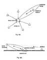
- the ideal base station antenna patternis a beam of narrow angular width as shown in Fig 1a.
- the narrow beamis directed at the wanted mobile, is narrow in both the azimuth and elevation planes, and tracks the mobile's movements.
- Such a beamwill have the dual benefits of having high gain, leading to increased range in thermal noise limited initial deployments, and rejecting interference from co-channel reuse cells allowing higher capacity without cell splitting in mature deployments.
- the narrow beamreduces interference in a balanced manner on the uplink and downlink. On the uplink the base station receiver is protected from interference generated by mobile station transmitters in the co-channel reuse cells, Fig 1b.
- the mobileOn the downlink the mobile is unlikely to be in the beams of the base station transmitters in the co-channel reuse cells.
- the extent of the advantage of a narrow beam antenna over an omni-directional antennais a function of the beamwidth. The narrower the beamwidth the greater the advantage, but this must be traded off against the increased size and complexity of the antenna.
- the narrow beamis formed at radio frequencies (typically in the 900 or 1800 MHz bands) it can usefully be visualised as analogous to a laser beam that emanates from the base station and tracks the mobiles.
- radio frequenciestypically in the 900 or 1800 MHz bands
- the use of the word "omni"is intended to convey the meaning of having radiation coverage over the area corresponding to the required geographic area of the cell.
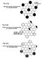
- An omni-directional base station antennawill receive interference from all six first tier reuse cells, Fig 2a. If an antenna with nominally 120° beamwidth is used, corresponding to a tri-sectored configuration, interference will be received from only two first tier reuse cells, Fig. 2b. If an antenna with 60° beamwidth is used, corresponding to a hex-sectored configuration, interference will be received from only one of the first tier cells, Fig. 2c. In sectorised cells the cellular radio transceivers at the base station are only connected to one sector (or antenna) and cannot be used in other sectors within the same cell.
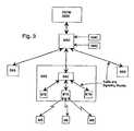
- a standard cellular radio systemis comprised of several layers, as shown in Fig. 3.
- a Mobile Switching Centreis the interface between the cellular system and other networks, e.g. PSTN, Public Switched Telephone Network or ISDN, Integrated Services Digital Network.
- Each MSCcontrols several Base Station Systems (BSS), which in some systems, such as GSM or PCS, are further divided into a Base Station Controller (BSC) which controls Several Base Transceiver Stations (BTS).
- BSCBase Station Controller
- BTSBase Transceiver Stations
- Each BSScommunicates with several Mobile Stations (MS).
- MSCOperations and Maintenance
- NMCNetwork Management
- the callsare allocated to transceivers at baseband in the cellular radio network, at either the BSC, if available, or at the MSC, as shown in Fig. 4a.
- Any change required in the call to transceiver allocationhas to be signalled through the network, maybe as far as the MSC and back again. This represents a heavy loading on the signalling network and a time delay whilst it occurs.
- a smart antenna as referred to hereinaftercomprises a plurality of antenna arrays each capable of forming a multiplicity of separate overlapping narrow beams in azimuth, the arrays being positioned such that the totality of beams formed by the arrays provides a substantially omni-directional coverage in azimuth, azimuth and elevation beamforming means for each array, a plurality of r.f. transceivers each for transmitting and receiving r.f.
- switching matrix meansfor connecting each transceiver with one or other of the arrays via the beamforming means
- control meansfor controlling the switch matrix means whereby a particular transceiver is connected to a particular array, via the beamforming means, to exchange r.f. signals with a remote station located in the area covered by one of the narrow beams.
- WO93/12590An alternative type of narrow beam antenna system is disclosed in WO93/12590.
- This systemutilises beam steering techniques wherein an assigned beam tracks a mobile station as it moves around a cellular coverage area.
- the beamsteering techniquesare similar to those used in phased array radar systems in which a beam is formed by an antenna array and directed at a mobile station using wave superposition principles. Such an arrangement requires sophisticated signal direction of arrival determination and beam steering control.
- an antenna arrangementcomprising:
- the present inventionprovides a method of operating an antenna arrangement comprising a plurality of antenna arrays, wherein each antenna array is capable of forming separate overlapping narrow beams fixed in azimuth, a plurality of radio frequency transceivers each for transmitting and receiving radio frequency signals for one or more calls, and switching matrix means operable to switch each transceiver through the switching matrix means to any array such that radio frequency call signals can be exchanged between any transceiver and a mobile station located in any area covered by the narrow beams; the method comprising: independently adjusting the transmitter radiated power level of individual beams.
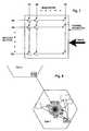
- the main elements of a smart antenna as shown in Fig. 5comprise a mast, tower or building 10 supporting the antenna array(s) 12 and associated antenna electronics unit 14, which includes beamformers, diplexers and amplifiers.
- the antenna electronics unit 14is connected via a cabin electronics unit 16 to the base station 18 that is under the control of a base station controller 20.
- the smart antenna systemreplaces the conventional passive antenna normally attached to the base station.
- the use of electronics in the mastheadallows the call switching to be carried out between the transceivers and antennas within the smart antenna, as shown in Fig. 4b. The switching now occurs on the r.f. signals and only requires local control from the attached base station. This requires a new interface link 17 to be established between the base station and the smart antenna system.
- the previous baseband informationis no longer required, reducing the loading on the signalling through the cellular radio network. It is replaced by r.f. assignment information on the new interface link between the base station and smart antenna. This interface is also used to convey control information from the MSC, OMC and NMC parts of the cellular system.
- base station networkis used to describe all parts of the cellular system prior to the smart antenna and its interface link, e.g. the radio, base station controller, mobile switching centre, operations and maintenance and network management.
- Each antenna array 40comprises a conventional array of individual antenna elements 42 arranged in rows and columns. Each column of elements is energised via an elevation beamforming network 44. Each elevation beamforming network combines the elements of a column to a single feed point. The amplitude and phase relationships of the r.f. signals coupled to the elevation beamformer determine the elevation beam pattern of the antenna for both transmit and receive. Each elevation beamformer is coupled to the azimuth beamformer 46. The azimuth beamformer has multiple ports for both transmit and receive, one for each elevation beamformer.
- the phase and amplitude relationship of the r.f. signals coupled to the elevation beamformerscontrol the azimuth beam pattern for both transmit and receive.
- the azimuth beamformeris prior to the low noise amplifiers on the receive path it must be optimised for low loss in that path.
- One well-known type of beamformeris the Butler matrix.
- the transmit and receive signals for the azimuth beamformerare coupled to the beamformer via individual diplexers 48. Filters that cover just the transmit or receive frequency bands respectively can be used for this purpose.
- the diplexers 48are fed via a combiner 50 from separate single carrier power amplifiers 52. These amplify the r.f. signals up to the power levels required for transmission.
- the diplexers 48feed separate substantially identical low noise amplifiers 62, one for each azimuth beam. The low noise amplifiers are required to amplify the weak received r.f. signals prior to any system losses to establish a low noise figure (high sensitivity) in the subsequent receive path.
- signalsare passed from the low noise amplifiers 62 to the receive splitter 74.
- signalsare passed to the single carrier transmit amplifiers from cell shaping attenuators 54.
- the attenuatorsare controlled by the operator via the masthead control electronics.
- the cell shaping attenuatorsare situated prior to the amplifiers, to enable low power standard attenuators to be used. By placing them prior to the combiner the intermodulation performance is improved, due to each being at a single frequency.
- Signalsare passed from the transceivers 84 to the cell shaping attenuators, by a switching system, via an optional phase hopping module 66.
- Thisensures that all transmitters can be connected to any beamformer input, however only one transmitter is connected to any one of the single carrier power amplifiers, at any time.
- the switching systemcomprises several levels of switching or splitting, which ensures primarily maximum redundancy on the omni path and secondarily some redundancy in the traffic paths.
- the transceivers 84if required can be input to an n*n transmit switch matrix 78, where n is equal to the number of transceivers.
- the transmit switch matrixallows any one input to be connected to any one output, but not more than one input to any one output simultaneously.
- a combination of switches and splitters 56, 58, 68is used to ensure that the omni path is routed to every beam, whilst a single traffic channel only goes to one beam.
- This switching and splitting functionmay be placed either at the top or the bottom of the mast or a combination of both as shown in Fig. 6.
- the preferred methodis to have the main facet switches 68 at the bottom of the mast and then each transceiver path is split to every beam, via the beam splitter 58, where the amplifier select switch matrix 56 switches off the beams not required. This makes the implementation of the dual transmit beam concept far easier and ensures that the lower reliability components are in the cabin where access is easier.
- the transmit, receive and amplifier select switch matricescomprise an r.f. cross-bar switch that allows any of its inputs to be connected to any of it's outputs.
- the switch matrix designis such that any number of transmitters or receivers can be connected simultaneously to any one beamformer port, thus, if necessary, all the transmitters can be connected to one beam port at a given time. Likewise all the receivers can be connected, if necessary, to the same beam port at the same time. In practice, should there be more transceivers than a single beam can handle, the number of transmitters that can be connected to the beam port is limited by the number of Tx power amplifiers 52.
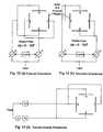
- the switch matricesare operated under the control of a control processor 80. A typical switch matrix structure is illustrated in Fig. 7.
- the receive splitter 74ensures that all incoming signals, from each beam, are sent to the interference discriminator 70; the parallel receivers 72 and both the main and diverse receive switch matrices 82.
- the interference discriminator 70is used to identify whether or not the incoming signal is from a mobile in its own cell, or one of a nearby cell or any other spurious source.
- the parallel receiversonly assess signal strength, however, one of the strongest signals may not be from a mobile within the cell, as shown by the direct path signal from MS2 in Fig. 8. If these errant signals are not identified, it can lead to errors in the processing within the base station. All transmissions between a mobile and a base station contain a fixed pattern known as a training sequence, every base station within a given area has its own unique training sequence.
- the interference discriminatorselects one of the beams, in each timeslot, and searches for the training sequence within the received signal, usually using correlation techniques for digital signals.
- the beam that is selectedis dictated by the control processor, based on information received from the receive switch matrices and the interference discriminator. It does not necessarily look at every beam, only those considered to be the most likely contenders.
- the use of an interference discriminatoris one of the features of the smart antenna system which allows the frequency re-use number to be decreased.
- a bank of parallel receivers 72allow every receive channel to be monitored on every beam simultaneously. For each channel the receivers measure the quality of the wanted mobile signal present on each beam. The information on which is the 'best' beam is passed to the control processor. The quality measure used by the receivers will vary depending on the particular cellular system concerned. In simple cases the measure will be the highest power level in other cases carrier to interference ratio will be used.
- the basic function of the control processor 80is to control the transmit and receive switch matrices such that the best beam (normally the one pointing at the mobile stations geographic position) for a given channel is selected.
- the inputs to the control processorare the beam amplitude data from the parallel receivers and data from the control buses to the base station. The latter allow the control processor to monitor a given mobile station's assignment to various control and traffic channels in the system during the progress of a call. Knowledge of which channel the mobile is being moved to allows a prompt and non-disruptive assignment to the best beam.
- the control algorithms usedwill fall into two basic classes, one for initial acquisition of the best beam for a new call and one for tracking of the best beam when a call is in progress.
- the determination of beam selection on the uplinkis used to select the corresponding beam for the downlink.
- the information on a mobile's angular position, i.e. the present beam being used, together with real time tracking data from the tracking algorithm, involving range and angular velocity,is sent back, on the transceiver control bus via the BTS, to the BSC or MSC as required.
- This informationcan then be directed to the next cell into which the mobile will pass.
- the choice of this next cellis decided based upon polling of the surrounding cells, either by the mobile or by the base station controller. If it is by the base station controller, then the information from the smart antenna can be used to prioritise the polling sequence. This will enable the controller to reach the correct decision quicker, thus reducing the loading on the base station controller. Having chosen the correct cell, with a conventional omni receiver there is no advantage to knowing the approximate azimuth position of a mobile within that cell, however in a multiple beam antenna each beam must be monitored to find the one containing the mobile.
- Fig. 9shows a mobile passing through cell 1 and into cell 2.
- the tracking algorithm of the smart antenna in cell 1monitors the mobile's progress through beams 12, 11, 10 and 9 and can then give a quite accurate prediction to cell 2 that the mobile will appear in one of beams 18, 19 or 20.
- the main and diverse receive switch matricesoperate under the control of the control processor, on information derived from the parallel receivers, and select the strongest and second strongest signals, respectively. These signals are then coupled by r.f. bus paths to the main and diverse ports of the bank of transceivers 84, one for each channel to be provided by the base station, where they are input to a maximal ratio combiner, of the type described in Mobile Communications Systems by J D Parsons et al, Blackie 1989.
- the transceiversare operated under the control of the base station controller 88, which also provides overall control for the switch matrix control processor 80.
- the transceiver control bus 86provides the communication link between the base station and the smart antenna.
- the communication linkwill be comprised of several buses, whose format will vary according to the type of base station to which the smart antenna is attached. Wherever possible the bus structure in the smart antenna will utilise the bus protocol of the base station. In the current implementation there are five bus types that carry the information outlined below:
- the actual physical link used for communication between the smart antenna and the BSC and/or MSCwill preferably be the existing signalling link, however a separate link as shown in Fig. 10 may also be used.
- the smart antennaappears as an omni-directional cell site. Since any transceiver can be switched to any beam and hence look in any direction, there are no sectors. Thus, within the network all signalling and processing associated with sector to sector hand-offs are eliminated. Also the fact that transceivers can be used in any direction eliminates the trunking inefficiency of sectorised sites. These factors not only eliminate a significant load from the network but allow the antenna system to utilise effectively narrower beamwidths than would otherwise be possible.
- An omni patternis still necessary as a cellular radio base station is required to radiate the BCCh channel over its total arc of coverage, at maximum power, in all time slots. It may also be required to radiate other carriers at times with the full arc of coverage. In conventional base station configurations this is achieved by the use of a single omni or a tri-sectored antenna system with all carriers having the same coverage pattern.
- a smart antenna arrangementhowever, a different situation exists, in that traffic channels are radiated using selected narrow beams whilst the base station appears omni-directional to the cellular system. In order to achieve this the antenna arrangement must generate both directional and omni-directional patterns simultaneously.
- the smart antennais made of a number of facets each covering a given sector, such that the total coverage is 360°.
- Each sectorcontains a number of beams which generate a sectoral pattern. This can be achieved using a beam set generated using, for example, a Butler Matrix. Such a set of beams when simultaneously excited by an r.f. carrier will produce a sectoral pattern with minimal ripple.
- nullsare produced in the pattern whose position and depths are dependant on the phase centre separation, the rate of cut off of the individual sectoral patterns, electrical phasing errors and mechanical positioning tolerances.
- a pictorial representation of a typical null pattern at the interfacet region for a four facet mountingis shown in Fig. 11.
- this first nullassuming perfect phasing and mechanical alignment will occur some 5.6 degrees from the facet intersect and have a depth of some 6- 7 dB that is more than can be tolerated. In many installations, e.g. those round buildings spacing of 100 or more wavelengths may be required leading to very deep nulls indeed.
- Fig. 11also shows, overlaid on the null pattern, a thick dashed line illustrating the improvement obtained when using phase hopping.
- phase hoppingWith phase hopping the array of facets are fed as two or more groups with no two adjacent facets being fed from the same output of the phase hopping module.
- An example of such a phase hopping moduleis shown in Fig. 12a.
- the arrayconsists of four facets each covering a 90 degree sector.
- the diametrically opposite facetsare connected to the same feed via a power splitter.
- Each of these pairs of feedsis moved in phase relative to each other, by the use of a phase shifter. This can be achieved by a single 360 degree phase shifter in one arm.
- two lesser value phase shifterscapable of providing the full 360 degree relative phase shift placed one in each arm could be used. This latter system in practice will give a better amplitude balance.
- the phase shiftersare controlled in such a way as to vary the relative phase of the facets through 360 degrees, in a suitable time scale for the system in question to integrate the received energy and maintain a best average link.
- thisis perhaps best achieved by stepping the phase on a time slot by time slot basis using say 16 steps controlled in a pseudo random manner.
- the use of a stepped wave form in this caseprevents degradation of the phase trajectory response that would occur for a linear phase shift.
- the randomisation of the phasingis to prevent any cyclic interference with the various GSM message formats that occur on a multi-frame basis.
- the effective loss of such a systemis a maximum of approximately 2dB relative to the optimally combined signals when both signals have equal amplitude, being a lesser value for unequal amplitude signals.
- Fig. 12bAn alternative method that will be viable in certain situations is shown in Fig. 12b.
- This methodinvolves phase hopping between adjacent facets on one of the diagonals, e.g. the interfacet region between 1 & 2 and between 3 & 0, but not between 0 & 1 or 2 & 3. This can only be achieved if the facet phase centres of the latter two pairs (0 & 1 and 2 & 3) are sufficiently close together to enable a good beam pattern to be obtained at this non-cycled interfacet region.
- Fig. 12cA method that will in effect phase cycle the interfacet region is shown in Fig. 12c.
- This methodinvolves the use of transmit diversity, the main and diverse ports of the transmitters being connected to adjacent facets.
- the diverse portcontains the same signal as the main port but delayed in time.
- GMSK modulationas used in GSM and DCS1800, alternate bits will have an offset from the previous bit equal to a multiple of 90°. This will provide the facets with random 90° phase changes, a form of phase hopping.
- the position of the amplifiers 50, 52 at the top of the mast or buildingis the key to the whole architecture. Firstly the concept of switching the transmitters to any beam is impractical unless it can be achieved without generating intermodulation products, or at least maintaining them at a very low level. This is not possible if one were to attempt to switch the power levels, which can be as high as 50 watts, at the transceiver outputs. It is necessary to switch before power amplification. Secondly if power amplification takes place at the foot of the mast or building, the r.f. feeder cables must be very low loss and become large and expensive. This would be a significant practical limitation on the number of beams one could have in a system.
- the positioning of the single carrier power amplifiers 52 prior to the diplexers 48 that are prior to the azimuth beamformerprovides an excellent compromise between the above factors and cost. If a complete single carrier power amplifier was to fail (which is unlikely because of their simple hybrid design that leads to high reliability) the main effect would be a reduction in traffic capacity in only one beam. The omni pattern would remain unaffected as this takes precedence in amplifier allocation via the switch matrices.
- the use of single carrier amplifiersreduces the problems with intermodulation products. Positioning the diplexers prior to the azimuth beamformer requires fewer diplexers that proves to be a more cost effective solution. It also simplifies the control of the amplitude ripple across the beams required for the omni pattern.
- a potential disadvantage of the inventionis that a relatively large antenna aperture, in terms of wavelengths, is needed to produce the narrow beams. If the antenna aperture were very large this could create aesthetic and structural problems, due to wind loading, etc., in some sites.
- This potential disadvantageis overcome by using the same antenna array 40 for transmit and receive. In this way the outline of the antenna, for reasonable beamwidth, is less than that of many conventional cell sites.
- the diplexing of transmit and receive through the common apertureis a key feature of the architecture.
- This type of antennaalso has the potential disadvantage that it does not readily lend itself to the doubling of antenna elements required to gain spatial diversity in the receive path.
- Spatial diversityis the most common method currently in use to overcome the problems of multipath.
- the smart antennacan overcome this problem by using angular diversity, due to the fact that it has a separate incoming signal in each one of its multiplicity of beams. These can be compared with the two largest signals selected, in the receive switch matrices, and hence diversity can be maintained.
- the advantages gained from this inventionare twofold, depending on whether the cellular base transceiver station is sited in an area of high or low multipath.
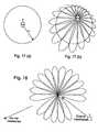
- the antennareceives strong scattered signals from widely separated angles as shown in Fig 13a.
- the antennawill select the two strongest signals, regardless of in which beam they appear, these could for example be beams B8 and B17 or any combination of the beams shown.
- These two signalscan then be routed to the main and diverse ports of any maximal ratio combiner to maximise receive power and give diversity gain to the system.
- the two strongest signalswill normally be in adjacent beams, as shown for the mobile station in Fig 13b.
- the two strongest signalswill again provide the inputs to a maximal ratio combiner as for the high multipath case. Due to the fact that the beams are orthogonal the resultant signal will in effect "fill in” most of the cusp between the two beams.
- the ripple in the omni patternwill be reduced from approximately 3.9dB to the order of 0.9dB, as shown by the shaded area in Fig. 13b, resulting in a possible 3dB gain in received signal power.
- the switching systemwill ensure that the signal is fed to the two adjacent beams. Dual transmission will only occur if the smart antenna predicts the mobile to be passing through the cusp or the received signal from the mobile is very weak.
- the use of beam splitters to feed the same signal to all beamsreduces the complexity of the implementation.
- the two beamscan be fed either in phase or in quadrature depending upon the circumstances.
- the two beamscan be fed at full power in phase, as shown in Fig. 14a, if there is no ERP limitation or if the smart antenna is operating at least 3dB below the limit.
- Fig. 15illustrates the system operation.
- Fig. 15ashows the concept of a multiplicity of narrow, overlapping beams covering the cell area surrounding the base station. The beams are referenced b1 - b20.
- Fig. 15bshows how, at time t 1 four mobile stations ms1 - ms4 are served by beams b2, b8 and b17.
- Beam b2serves two mobile stations ms2 and ms3 at this time.
- beam b18now serves mobile station ms1
- b4serves ms3
- b7serves ms4.
- Mobile station ms2has at time t 2 moved out of the cell coverage of this base station and will now be served by an adjoining base station (not shown).
- cell shaping attenuatorsenables the contour of the ideal cell illustrated in Fig 15a to be altered.
- This featurehas several advantages for the cell planner and the operator; such as the reduction of handovers and lower interference levels, by removing large areas of overlap; flexibility of base station location; avoidance of interference sources and congestion management, each of which will be described individually.
- Fig. 16aillustrates a typical cell layout, using three cell sizes and the shaded areas indicate the regions of overlap. It is obvious that there are quite large areas of overlap, along the boundaries between regions of different cell sizes. Areas of overlap can also exist between cells of the same size due to shadowing effects and the canyon effect of streets in large cities, etc.
- Fig 16bshows that by adjusting the power levels in each of the beams for cells A4, B9 and B11 the areas of overlap can be greatly reduced. This will reduce the conflict about which base station is handling a mobile and the interference caused by overlapping coverage areas. It will also result in a reduction in power consumption for individual cells.
- Fig. 17ashows that to get a coverage of an approximate radius R a conventional BTS must be sited close to the centre of the cell.
- the present inventiondue to its cell dimensioning capability allows the operator a lot more flexibility in the siting of the base station, as can be seen in Fig 17b. This can result in a financial saving to the operator, by allowing the choice of cheaper sites.
- This inventionalso has the means to manage the coverage area around potential sources of interference (or where the BTS would be the interferer) with the minimum loss of mobile coverage. By attenuating just one, or several adjacent beams, it is possible to put a notch in the antenna footprint, effectively acting as an interference cancellor in a particular direction, as shown in Fig. 18.
- Cell Dimensioningcan also be used to dynamically control periodic congestion in cells. Considering Fig. 19, if cell A always experiences much higher traffic density during the morning period, for example, then cells B and C can be increased to reduce the size of cell A (the shaded area), hence relieving some of the congestion. Later in the day the congestion may then appear in cell C and cells A and B can be increased to lower the traffic density in cell C. Periodic adjustments in the cell boundaries can be achieved wherever the traffic density fluctuates in a known manner during a fixed period of time. Cell sizes can only be increased in the limit of the transmit power of the antenna, or an imposed ERP limit.
- This featurecan also be used to enable maintenance work to be carried out when the cell utilisation is low.
- One cellcan be switched off and its neighbouring cells will increase their size to cover the cell, without any loss of coverage.
Landscapes
- Engineering & Computer Science (AREA)
- Computer Networks & Wireless Communication (AREA)
- Signal Processing (AREA)
- Mobile Radio Communication Systems (AREA)
- Variable-Direction Aerials And Aerial Arrays (AREA)
- Radio Transmission System (AREA)
Description
- This invention relates to a base station antenna arrangement, for usein a Cellular Radio communications system, which shall hereafter bereferred to as a smart antenna.
- Cellular radio systems are currently in widespread use throughout theworld providing telecommunications to mobile users. In order to meetthe capacity demand, within the available frequency band allocation,cellular radio systems divide a geographic area to be covered intocells. At the centre of each cell is a base station, through which themobile stations communicate. The available communication channelsare divided between the cells such that the same group of channelsare reused by certain cells. The distance between the reused cells isplanned such that the co-channel interference is maintained at atolerable level.
- When a new cellular radio system is initially deployed, operators areoften interested in maximising the uplink (mobile station to basestation) and downlink (base station to mobile station) range. Theranges in many systems are uplink limited due to the relatively lowtransmitted power levels of hand portable mobile stations. Anyincrease in range means that less cells are required to cover a givengeographic area, hence reducing the number of base stations andassociated infrastructure costs.
- When a cellular radio system is mature the capacity demand can oftenincrease, especially in cities, to a point where more, smaller size cellsare needed in order to meet the required capacity per unit area. Theprocess used to create these smaller cells is known as cell splitting.Any technique that can provide additional capacity without the need for cell-splitting will again reduce the number of base station sites andassociated infrastructure costs.
- The antenna used at the base station site can potentially makesignificant improvements to the range and capacity of a cellular radiosystem. The ideal base station antenna pattern is a beam of narrowangular width as shown in Fig 1a. The narrow beam is directed at thewanted mobile, is narrow in both the azimuth and elevation planes, andtracks the mobile's movements. When compared to an omni-directionalantenna, such a beam will have the dual benefits of having high gain,leading to increased range in thermal noise limited initial deployments,and rejecting interference from co-channel reuse cells allowing highercapacity without cell splitting in mature deployments. The narrow beamreduces interference in a balanced manner on the uplink and downlink.On the uplink the base station receiver is protected from interferencegenerated by mobile station transmitters in the co-channel reuse cells,Fig 1b. On the downlink the mobile is unlikely to be in the beams of thebase station transmitters in the co-channel reuse cells. The extent ofthe advantage of a narrow beam antenna over an omni-directionalantenna is a function of the beamwidth. The narrower the beamwidththe greater the advantage, but this must be traded off against theincreased size and complexity of the antenna.
- Although the narrow beam is formed at radio frequencies (typically inthe 900 or 1800 MHz bands) it can usefully be visualised as analogousto a laser beam that emanates from the base station and tracks themobiles. When contrasted with an omni-directional antenna, this clearlycreates a high quality transmission path with minimal interference. Forthe purposes of this document the use of the word "omni" is intendedto convey the meaning of having radiation coverage over the areacorresponding to the required geographic area of the cell.
- Some of the potential benefits of narrow beam antennas, for cellularradio, have been recognised in the literature, see for example "ASpectrum Efficient Cellular Base Station Antenna Architecture", S.C.Swales and M.A. Beach, Personal & Mobile Radio CommunicationsConference, Warwick, 1991 and "Proposed Advanced Base StationEAntennas for Future Cellular Mobile Radio Systems", W.S. Davies, R.J. Long and E. Vinnal, Australian Telecomms Research, Vol. 22, No.1, pp 53-60. Within current systems the manner in which directiveantennae are used allows relatively small benefits to be obtained. Theuse of directive antennas in current cellular radio systems is based onthe principle of sectorisation as illustrated in Fig 2. The main sources ofinterference, in a cellular system, come from the so called first tierreuse cells. An omni-directional base station antenna will receiveinterference from all six first tier reuse cells, Fig 2a. If an antenna withnominally 120° beamwidth is used, corresponding to a tri-sectoredconfiguration, interference will be received from only two first tier reusecells, Fig. 2b. If an antenna with 60° beamwidth is used, correspondingto a hex-sectored configuration, interference will be received from onlyone of the first tier cells, Fig. 2c. In sectorised cells the cellular radiotransceivers at the base station are only connected to one sector (orantenna) and cannot be used in other sectors within the same cell.
- The sectorised approach to the use of directive antennas has reachedits useful limit at 60° beamwidth and can go no further. There are twokey disadvantages of the approach:
- a) The cellular radio transceivers are dedicated to particularsectors that leads to significant levels of trunking inefficiency. Inpractice this means that many more transceivers are needed at thebase station site than for an omni-directional cell of the same capacity.
- b) Each sector is treated by the cellular radio network (i.e. the basestation controller and mobile switches) as a separate cell. This meansthat as the mobile moves between sectors, a considerable interactionis required, between the base station and the network, to hand off thecall, between sectors of the same base station. This interaction,comprising signalling and processing at the base station controller andswitch, represents a high overhead on the network and reducescapacity.
- A standard cellular radio system is comprised of several layers, asshown in Fig. 3. A Mobile Switching Centre (MSC) is the interfacebetween the cellular system and other networks, e.g. PSTN, PublicSwitched Telephone Network or ISDN, Integrated Services DigitalNetwork. Each MSC controls several Base Station Systems (BSS),which in some systems, such as GSM or PCS, are further divided into a Base Station Controller (BSC) which controls Several Base TransceiverStations (BTS). Each BSS communicates with several Mobile Stations (MS). Atthe MSC level there are also other facilities such as Operations and Maintenance(OMC) and Network Management (NMC).
- In this system the calls are allocated to transceivers at baseband in the cellularradio network, at either the BSC, if available, or at the MSC, as shown in Fig. 4a.Any change required in the call to transceiver allocation has to be signalledthrough the network, maybe as far as the MSC and back again. This represents aheavy loading on the signalling network and a time delay whilst it occurs.
- The basic concept of a smart antenna is disclosed in European PatentPublication No.
EP 0 593 822. A smart antenna as referred to hereinaftercomprises a plurality of antenna arrays each capable of forming a multiplicity ofseparate overlapping narrow beams in azimuth, the arrays being positioned suchthat the totality of beams formed by the arrays provides a substantially omni-directionalcoverage in azimuth, azimuth and elevation beamforming means foreach array, a plurality of r.f. transceivers each for transmitting and receiving r.f.signals for one or more calls, switching matrix means for connecting eachtransceiver with one or other of the arrays via the beamforming means, controlmeans for controlling the switch matrix means whereby a particular transceiver isconnected to a particular array, via the beamforming means, to exchange r.f.signals with a remote station located in the area covered by one of the narrowbeams. - An alternative type of narrow beam antenna system is disclosed in WO93/12590.This system utilises beam steering techniques wherein an assigned beam tracks amobile station as it moves around a cellular coverage area. The beamsteeringtechniques are similar to those used in phased array radar systems in which a beamis formed by an antenna array and directed at a mobile station using wavesuperposition principles. Such an arrangement requires sophisticated signaldirection of arrival determination and beam steering control.
- According to the present invention there is provided an antenna arrangementcomprising:
- a plurality of antenna arrays, wherein each antenna array is capable of formingseparate overlapping narrow beams fixed in azimuth,
- a plurality of radio frequency transceivers each for transmitting and receivingradio frequency signals for one or more calls, and
- switching matrix means operable to switch each transceiver through the switchingmatrix means to any array such that radio frequency call signals can beexchanged between any transceiver and a mobile station located in any areacovered by the narrow beams; characterised in that means (54; Fig. 6a) are provided for independentadjustment of the transmitter radiated power level of individual beams.
- According to a second aspect the present invention provides a method ofoperating an antenna arrangement comprising a plurality of antenna arrays,wherein each antenna array is capable of forming separate overlapping narrowbeams fixed in azimuth,
a plurality of radio frequency transceivers each for transmitting and receivingradio frequency signals for one or more calls, and
switching matrix means operable to switch each transceiver through the switchingmatrix means to any array such that radio frequency call signals can beexchanged between any transceiver and a mobile station located in any areacovered by the narrow beams;
the method comprising: independently adjusting the transmitter radiated powerlevel of individual beams. - Embodiments of the invention will now be described with reference to theaccompanying drawings, in which:
- Figs. 1a and 1b illustrate schematically the use of a narrow beam antenna tocommunicate between a base station and a mobile station,
- Figs. 2a-2c illustrate schematically the principle of sectorisation of a base station,
- Fig. 3 is a block diagram of the main elements of a cellular system,
- Figs 4a and 4b illustrate the differences in call handling between a conventionalcellular system and one using a smart antenna,
- Fig. 5 is a block diagram of the main elements of a base station,
- Figs. 6a and 6b are diagrams of the constituents of a multiplenarrow beam base station,
- Fig. 7 illustrates the basic principle of a switching matrix,
- Fig. 8 illustrates schematically the use of an interferencedetector,
- Fig. 9 illustrates schematically the use of assisted handovermanagement,
- Fig. 10 is a block diagram of the communication link betweenthe smart antenna and the rest of a cellular system,
- Fig. 11 illustrates pictorially the interfacet radiation pattern of amultifaceted system with and without the use of phase hopping,
- Figs. 12a 12c are diagrams of different embodiments of phasehopping,
- Figs. 13a and 13b illustrate schematically the principles ofangular diversity,
- Figs. 14a - 14c are diagrams of different embodiments of thedual transmit beam system with an illustration of the relativeradiation pattern improvements to be found,
- Figs. 15a - 15c illustrate the operation of a multiple narrow beambase station,
- Figs. 16a and 16b illustrate schematically the reduced overlap atdiffering cell radii boundaries using cell dimensioning,
- Figs. 17a and 17b illustrate schematically the flexibility in basestation location by the use of cell dimensioning,
- Fig. 18 illustrates schematically the use of cell dimensioning toreduce interference problems, and
- Fig. 19 illustrates schematically the use of cell dimensioning toavoid congestion.
- The main elements of a smart antenna as shown in Fig. 5 comprise amast, tower or building 10 supporting the antenna array(s) 12 andassociated
antenna electronics unit 14, which includes beamformers,diplexers and amplifiers. Theantenna electronics unit 14 is connectedvia acabin electronics unit 16 to thebase station 18 that is under thecontrol of abase station controller 20. The smart antenna systemreplaces the conventional passive antenna normally attached to thebase station. The use of electronics in the masthead allows the call switching to be carried out between the transceivers and antennaswithin the smart antenna, as shown in Fig. 4b. The switching nowoccurs on the r.f. signals and only requires local control from theattached base station. This requires anew interface link 17 to beestablished between the base station and the smart antenna system.The previous baseband information is no longer required, reducing theloading on the signalling through the cellular radio network. It isreplaced by r.f. assignment information on the new interface linkbetween the base station and smart antenna. This interface is alsoused to convey control information from the MSC, OMC and NMCparts of the cellular system. - For the purposes of this description the term "base station network" isused to describe all parts of the cellular system prior to the smartantenna and its interface link, e.g. the radio, base station controller,mobile switching centre, operations and maintenance and networkmanagement.
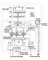
- The detailed constituents of the smart antenna are shown in Fig. 6.The masthead antenna electronics is shown in Fig. 6a and the cabinelectronics in Fig. 6b. Only one of the antenna arrays is depicted. Each
antenna array 40 comprises a conventional array ofindividual antennaelements 42 arranged in rows and columns. Each column of elementsis energised via anelevation beamforming network 44. Each elevationbeamforming network combines the elements of a column to a singlefeed point. The amplitude and phase relationships of the r.f. signalscoupled to the elevation beamformer determine the elevation beampattern of the antenna for both transmit and receive. Each elevationbeamformer is coupled to theazimuth beamformer 46. The azimuthbeamformer has multiple ports for both transmit and receive, one foreach elevation beamformer. The phase and amplitude relationship ofthe r.f. signals coupled to the elevation beamformers control theazimuth beam pattern for both transmit and receive. As the azimuthbeamformer is prior to the low noise amplifiers on the receive path itmust be optimised for low loss in that path. One well-known type ofbeamformer is the Butler matrix. - The transmit and receive signals for the azimuth beamformer arecoupled to the beamformer via
individual diplexers 48. Filters thatcover just the transmit or receive frequency bands respectively can beused for this purpose. In the transmit path thediplexers 48 are fed viaacombiner 50 from separate singlecarrier power amplifiers 52. Theseamplify the r.f. signals up to the power levels required for transmission.In the receive path thediplexers 48 feed separate substantiallyidenticallow noise amplifiers 62, one for each azimuth beam. The lownoise amplifiers are required to amplify the weak received r.f. signalsprior to any system losses to establish a low noise figure (highsensitivity) in the subsequent receive path. - In the receive path, signals are passed from the
low noise amplifiers 62to the receivesplitter 74. On the transmit side, signals are passed tothe single carrier transmit amplifiers fromcell shaping attenuators 54.There is one cell shaping attenuator per transmit amplifier. Allattenuators in any one beam are set to the same value to give a newbeam template across all frequencies. This sets the maximum range ina particular direction, however the power required to reach a particularmobile in the beam can be reduced from this if necessary. Theattenuators are controlled by the operator via the masthead controlelectronics. The cell shaping attenuators are situated prior to theamplifiers, to enable low power standard attenuators to be used. Byplacing them prior to the combiner the intermodulation performance isimproved, due to each being at a single frequency. - Signals are passed from the
transceivers 84 to the cell shapingattenuators, by a switching system, via an optionalphase hoppingmodule 66. This ensures that all transmitters can be connected to anybeamformer input, however only one transmitter is connected to anyone of the single carrier power amplifiers, at any time. The switchingsystem comprises several levels of switching or splitting, whichensures primarily maximum redundancy on the omni path andsecondarily some redundancy in the traffic paths. Thetransceivers 84,if required can be input to an n*n transmitswitch matrix 78, where n isequal to the number of transceivers. The transmit switch matrix allowsany one input to be connected to any one output, but not more thanone input to any one output simultaneously. This allows for redundancy should any cable in the mast fail, however the same function can beaccomplished by the BTS if a suitable command interface exists. Acombination of switches andsplitters beam splitter 58, where the amplifierselect switch matrix 56 switches off the beams not required. Thismakes the implementation of the dual transmit beam concept far easierand ensures that the lower reliability components are in the cabinwhere access is easier. - The transmit, receive and amplifier select switch matrices comprise anr.f. cross-bar switch that allows any of its inputs to be connected to anyof it's outputs. The switch matrix design is such that any number oftransmitters or receivers can be connected simultaneously to any onebeamformer port, thus, if necessary, all the transmitters can beconnected to one beam port at a given time. Likewise all the receiverscan be connected, if necessary, to the same beam port at the sametime. In practice, should there be more transceivers than a single beamcan handle, the number of transmitters that can be connected to thebeam port is limited by the number of
Tx power amplifiers 52. Theswitch matrices are operated under the control of acontrol processor 80. A typical switch matrix structure is illustrated in Fig. 7. - The receive
splitter 74 ensures that all incoming signals, from eachbeam, are sent to theinterference discriminator 70; theparallelreceivers 72 and both the main and diverse receiveswitch matrices 82. - The
interference discriminator 70 is used to identify whether or not theincoming signal is from a mobile in its own cell, or one of a nearby cellor any other spurious source. The parallel receivers only assess signalstrength, however, one of the strongest signals may not be from amobile within the cell, as shown by the direct path signal from MS2 inFig. 8. If these errant signals are not identified, it can lead to errors inthe processing within the base station. All transmissions between a mobile and a base station contain a fixed pattern known as a trainingsequence, every base station within a given area has its own uniquetraining sequence. The interference discriminator selects one of thebeams, in each timeslot, and searches for the training sequence withinthe received signal, usually using correlation techniques for digitalsignals. The beam that is selected is dictated by the control processor,based on information received from the receive switch matrices andthe interference discriminator. It does not necessarily look at everybeam, only those considered to be the most likely contenders. The useof an interference discriminator is one of the features of the smartantenna system which allows the frequency re-use number to bedecreased. - A bank of
parallel receivers 72, one for each beam, allow every receivechannel to be monitored on every beam simultaneously. For eachchannel the receivers measure the quality of the wanted mobile signalpresent on each beam. The information on which is the 'best' beam ispassed to the control processor. The quality measure used by thereceivers will vary depending on the particular cellular systemconcerned. In simple cases the measure will be the highest power levelin other cases carrier to interference ratio will be used. - The basic function of the
control processor 80 is to control the transmitand receive switch matrices such that the best beam (normally the onepointing at the mobile stations geographic position) for a given channelis selected. The inputs to the control processor are the beam amplitudedata from the parallel receivers and data from the control buses to thebase station. The latter allow the control processor to monitor a givenmobile station's assignment to various control and traffic channels inthe system during the progress of a call. Knowledge of which channelthe mobile is being moved to allows a prompt and non-disruptiveassignment to the best beam. The control algorithms used will fall intotwo basic classes, one for initial acquisition of the best beam for a newcall and one for tracking of the best beam when a call is in progress. Itis anticipated that due to different multipath conditions the parameterswithin the control algorithms will vary for rural and urban cells. Thedetermination of beam selection on the uplink is used to select thecorresponding beam for the downlink. The information on a mobile's angular position, i.e. the present beam being used, together with realtime tracking data from the tracking algorithm, involving range andangular velocity, is sent back, on the transceiver control bus via theBTS, to the BSC or MSC as required. - This information can then be directed to the next cell into which themobile will pass. The choice of this next cell is decided based uponpolling of the surrounding cells, either by the mobile or by the basestation controller. If it is by the base station controller, then theinformation from the smart antenna can be used to prioritise the pollingsequence. This will enable the controller to reach the correct decisionquicker, thus reducing the loading on the base station controller.Having chosen the correct cell, with a conventional omni receiver thereis no advantage to knowing the approximate azimuth position of amobile within that cell, however in a multiple beam antenna each beammust be monitored to find the one containing the mobile. It is thereforea great advantage to know the approximate beam into which a mobilewill appear, so that the order in which the beams are analysed can beweighted to give priority to the known direction. Fig. 9 shows a mobilepassing through
cell 1 and intocell 2. The tracking algorithm of thesmart antenna incell 1 monitors the mobile's progress throughbeams cell 2that the mobile will appear in one ofbeams - The main and diverse receive switch matrices, operate under thecontrol of the control processor, on information derived from theparallel receivers, and select the strongest and second strongestsignals, respectively. These signals are then coupled by r.f. bus pathsto the main and diverse ports of the bank of
transceivers 84, one foreach channel to be provided by the base station, where they are inputto a maximal ratio combiner, of the type described in MobileCommunications Systems by J D Parsons et al, Blackie 1989. Thetransceivers are operated under the control of thebase stationcontroller 88, which also provides overall control for the switchmatrixcontrol processor 80. - The transceiver control bus 86 provides the communication linkbetween the base station and the smart antenna. The communication link will be comprised of several buses, whose format will varyaccording to the type of base station to which the smart antenna isattached. Wherever possible the bus structure in the smart antenna willutilise the bus protocol of the base station. In the currentimplementation there are five bus types that carry the informationoutlined below:
- 1. Operations and maintenance that carries configuration,supervision and alarm management information for general operationpurposes.
- 2. Operator controlled configuration information originating fromeither the BSC or the MSC.
- 3. Frequency values, timing information to identify position withinthe GSM frame structure, control information, beam power levels andmobile range. This is from the BTS to the smart antenna, with one busper transceiver.
- 4. Information about the mobile, e.g. signal strength, direction,beam number. This is from the smart antenna to the BTS.
- 5. Signal strobes.
- The actual physical link used for communication between the smartantenna and the BSC and/or MSC will preferably be the existingsignalling link, however a separate link as shown in Fig. 10 may alsobe used.
- The key features of the invention can now be considered in more detailand contrasted with the conventional sectorised base station. It is not asingle feature of the invention but rather the overall architecture (thefunctions and their precise disposition) which provides a practical andeconomic realisation of the narrow beam concept.
- Considered from the network viewpoint, the smart antenna appears asan omni-directional cell site. Since any transceiver can be switched toany beam and hence look in any direction, there are no sectors. Thus, within the network all signalling and processing associated with sectorto sector hand-offs are eliminated. Also the fact that transceivers canbe used in any direction eliminates the trunking inefficiency ofsectorised sites. These factors not only eliminate a significant loadfrom the network but allow the antenna system to utilise effectivelynarrower beamwidths than would otherwise be possible.
- An omni pattern is still necessary as a cellular radio base station isrequired to radiate the BCCh channel over its total arc of coverage, atmaximum power, in all time slots. It may also be required to radiateother carriers at times with the full arc of coverage. In conventionalbase station configurations this is achieved by the use of a single omnior a tri-sectored antenna system with all carriers having the samecoverage pattern. For a smart antenna arrangement, however, adifferent situation exists, in that traffic channels are radiated usingselected narrow beams whilst the base station appears omni-directionalto the cellular system. In order to achieve this the antennaarrangement must generate both directional and omni-directionalpatterns simultaneously. The smart antenna is made of a number offacets each covering a given sector, such that the total coverage is360°. Each sector contains a number of beams which generate asectoral pattern. This can be achieved using a beam set generatedusing, for example, a Butler Matrix. Such a set of beams whensimultaneously excited by an r.f. carrier will produce a sectoral patternwith minimal ripple.
- To produce an omni-directional pattern with minimum ripple it isnecessary to place each facet such that their phase centres arecoincident. This is clearly not possible. Practicality dictates that aminimum phase centre spacing of typically 5 or more wavelengthsspacing is required.
- When the phase centres are separated nulls are produced in thepattern whose position and depths are dependant on the phase centreseparation, the rate of cut off of the individual sectoral patterns,electrical phasing errors and mechanical positioning tolerances. Apictorial representation of a typical null pattern at the interfacet regionfor a four facet mounting is shown in Fig. 11. For the 5 wavelength spacing required in a realisable smart antenna this first null assumingperfect phasing and mechanical alignment will occur some 5.6 degreesfrom the facet intersect and have a depth of some 6- 7 dB that is morethan can be tolerated. In many installations, e.g. those round buildingsspacing of 100 or more wavelengths may be required leading to verydeep nulls indeed.
- This effect does not permit good omni-directional coverage to beobtained. Two possible solutions present themselves. First the cellcould be sectored removing the requirement for omni-directionalcoverage. This could be on the basis of either quad sectoring usingfour BCCh channels or bi-sectored using two BCCh channels pointingin opposite directions. The second solution, that is to be discussed indetail, is known as phase hopping, it is this solution that is proposed forthe generation of the omni directional pattern that will then have aneffective (time averaged) amplitude ripple of some 2 dB. Fig. 11 alsoshows, overlaid on the null pattern, a thick dashed line illustrating theimprovement obtained when using phase hopping.
- With phase hopping the array of facets are fed as two or more groupswith no two adjacent facets being fed from the same output of thephase hopping module. An example of such a phase hopping moduleis shown in Fig. 12a. In this case the array consists of four facets eachcovering a 90 degree sector. The diametrically opposite facets areconnected to the same feed via a power splitter. Each of these pairs offeeds is moved in phase relative to each other, by the use of a phaseshifter. This can be achieved by a single 360 degree phase shifter inone arm. Alternatively two lesser value phase shifters capable ofproviding the full 360 degree relative phase shift placed one in eacharm could be used. This latter system in practice will give a betteramplitude balance.
- The phase shifters are controlled in such a way as to vary the relativephase of the facets through 360 degrees, in a suitable time scale forthe system in question to integrate the received energy and maintain abest average link. In the case of the GSM/DCS1800 type wave formsthis is perhaps best achieved by stepping the phase on a time slot bytime slot basis using say 16 steps controlled in a pseudo random manner. The use of a stepped wave form in this case preventsdegradation of the phase trajectory response that would occur for alinear phase shift. The randomisation of the phasing is to prevent anycyclic interference with the various GSM message formats that occuron a multi-frame basis.
- The effective loss of such a system is a maximum of approximately2dB relative to the optimally combined signals when both signals haveequal amplitude, being a lesser value for unequal amplitude signals.With such a system, if the crossover level between facets is at -4dB,then a virtually uniform averaged omni pattern will result.
- An alternative method that will be viable in certain situations is shownin Fig. 12b. This method involves phase hopping between adjacentfacets on one of the diagonals, e.g. the interfacet region between 1 &2 and between 3 & 0, but not between 0 & 1 or 2 & 3. This can only beachieved if the facet phase centres of the latter two pairs (0 & 1 and 2& 3) are sufficiently close together to enable a good beam pattern to beobtained at this non-cycled interfacet region.
- A method that will in effect phase cycle the interfacet region is shownin Fig. 12c. This method involves the use of transmit diversity, the mainand diverse ports of the transmitters being connected to adjacentfacets. The diverse port contains the same signal as the main port butdelayed in time. With GMSK modulation, as used in GSM andDCS1800, alternate bits will have an offset from the previous bit equalto a multiple of 90°. This will provide the facets with random 90° phasechanges, a form of phase hopping.
- The position of the
amplifiers - By situating the amplifiers at the top of the mast or building the aboveproblems are solved. However, the precise position in the architecturewithin the antenna electronics unit is still critical. Also since theamplifiers are at the top of the mast they must be extremely reliableand failures should not produce catastrophic degradation in systemperformance.
- The positioning of the single
carrier power amplifiers 52 prior to thediplexers 48 that are prior to the azimuth beamformer provides anexcellent compromise between the above factors and cost. If acomplete single carrier power amplifier was to fail (which is unlikelybecause of their simple hybrid design that leads to high reliability) themain effect would be a reduction in traffic capacity in only one beam.The omni pattern would remain unaffected as this takes precedence inamplifier allocation via the switch matrices. The use of single carrieramplifiers reduces the problems with intermodulation products.Positioning the diplexers prior to the azimuth beamformer requiresfewer diplexers that proves to be a more cost effective solution. It alsosimplifies the control of the amplitude ripple across the beams requiredfor the omni pattern. - A potential disadvantage of the invention is that a relatively largeantenna aperture, in terms of wavelengths, is needed to produce thenarrow beams. If the antenna aperture were very large this couldcreate aesthetic and structural problems, due to wind loading, etc., insome sites. This potential disadvantage is overcome by using the
same antenna array 40 for transmit and receive. In this way the outlineof the antenna, for reasonable beamwidth, is less than that of manyconventional cell sites. Thus the diplexing of transmit and receivethrough the common aperture is a key feature of the architecture. - This type of antenna also has the potential disadvantage that it doesnot readily lend itself to the doubling of antenna elements required togain spatial diversity in the receive path. Spatial diversity is the mostcommon method currently in use to overcome the problems of multipath. The smart antenna can overcome this problem by usingangular diversity, due to the fact that it has a separate incoming signalin each one of its multiplicity of beams. These can be compared withthe two largest signals selected, in the receive switch matrices, andhence diversity can be maintained.
- The advantages gained from this invention are twofold, depending onwhether the cellular base transceiver station is sited in an area of highor low multipath. In a high multipath environment the antenna receivesstrong scattered signals from widely separated angles as shown in Fig13a. The antenna will select the two strongest signals, regardless of inwhich beam they appear, these could for example be beams B8 andB17 or any combination of the beams shown. These two signals canthen be routed to the main and diverse ports of any maximal ratiocombiner to maximise receive power and give diversity gain to thesystem.
- In a low multipath environment, where strong scattered signals are notas common, the two strongest signals will normally be in adjacentbeams, as shown for the mobile station in Fig 13b. The two strongestsignals will again provide the inputs to a maximal ratio combiner as forthe high multipath case. Due to the fact that the beams are orthogonalthe resultant signal will in effect "fill in" most of the cusp between thetwo beams. Hence in a low multipath environment the ripple in theomni pattern will be reduced from approximately 3.9dB to the order of0.9dB, as shown by the shaded area in Fig. 13b, resulting in a possible3dB gain in received signal power.
- Considering the improved coverage pattern shown in Fig. 13b, this canalso be achieved on the transmit side by the use of dual transmitbeams. When a mobile passes through the cusp, as shown in Fig. 13b,the switching system will ensure that the signal is fed to the twoadjacent beams. Dual transmission will only occur if the smart antennapredicts the mobile to be passing through the cusp or the receivedsignal from the mobile is very weak. The use of beam splitters to feedthe same signal to all beams reduces the complexity of theimplementation. The two beams can be fed either in phase or inquadrature depending upon the circumstances. The two beams can be fed at full power in phase, as shown in Fig. 14a, if there is no ERPlimitation or if the smart antenna is operating at least 3dB below thelimit. This will result in a 3dB improvement in peak signal power withthe 3dB cusp point at the previous peak level, as shown by the hatchedarea in Fig. 14c. If the system is operating close to the ERP limit thenthis method can only be used if the power level fed to the two beams isreduced and will not eliminate cusping completely. A preferred solutionin this instance is to feed the two beams in quadrature, as shown inFig. 14b. This will have the effect of filling the cusp, as shown by thesolid area in Fig. 14c, whilst not increasing the peak radiated powerlevel.
- Fig. 15 illustrates the system operation. Fig. 15a shows the concept ofa multiplicity of narrow, overlapping beams covering the cell areasurrounding the base station. The beams are referenced b1 - b20. Fig.15b shows how, at time t1 four mobile stations ms1 - ms4 are servedby beams b2, b8 and b17. Beam b2 serves two mobile stations ms2and ms3 at this time. As the mobile stations move geographically inrelation to the base station, at time t2 beam b18 now serves mobilestation ms1, b4 serves ms3 and b7 serves ms4. Mobile station ms2has at time t2 moved out of the cell coverage of this base station andwill now be served by an adjoining base station (not shown).
- The use of cell shaping attenuators enables the contour of the idealcell illustrated in Fig 15a to be altered. This feature has severaladvantages for the cell planner and the operator; such as the reductionof handovers and lower interference levels, by removing large areas ofoverlap; flexibility of base station location; avoidance of interferencesources and congestion management, each of which will be describedindividually.
- Cell planners usually use a hexagonal grid to obtain best coverage andinterference reduction. In rural areas cell size will be limited by thetransmit power of the mobiles and base stations, however in urbanareas, cells are also likely to be limited by co-channel interference. Cellplanners therefore have to be able to match together cells of differentsizes at cell split boundaries. Fig. 16a illustrates a typical cell layout,using three cell sizes and the shaded areas indicate the regions of overlap. It is obvious that there are quite large areas of overlap, alongthe boundaries between regions of different cell sizes. Areas of overlapcan also exist between cells of the same size due to shadowing effectsand the canyon effect of streets in large cities, etc.
- Large areas of overlap can cause problems with interference and witha much higher rate of handover, for mobiles, between cells, which canlead to a heavy loading on the network.. Fig 16b shows that byadjusting the power levels in each of the beams for cells A4, B9 andB11 the areas of overlap can be greatly reduced. This will reduce theconflict about which base station is handling a mobile and theinterference caused by overlapping coverage areas. It will also result ina reduction in power consumption for individual cells.
- With conventional base station antennas, once the cell grid has beendecided, the operator has little flexibility in where the base stations canbe sited. Fig. 17a shows that to get a coverage of an approximateradius R a conventional BTS must be sited close to the centre of thecell. The present invention, however, due to its cell dimensioningcapability allows the operator a lot more flexibility in the siting of thebase station, as can be seen in Fig 17b. This can result in a financialsaving to the operator, by allowing the choice of cheaper sites.
- This invention also has the means to manage the coverage areaaround potential sources of interference (or where the BTS would bethe interferer) with the minimum loss of mobile coverage. Byattenuating just one, or several adjacent beams, it is possible to put anotch in the antenna footprint, effectively acting as an interferencecancellor in a particular direction, as shown in Fig. 18.
- Cell Dimensioning can also be used to dynamically control periodiccongestion in cells. Considering Fig. 19, if cell A always experiencesmuch higher traffic density during the morning period, for example,then cells B and C can be increased to reduce the size of cell A (theshaded area), hence relieving some of the congestion. Later in the daythe congestion may then appear in cell C and cells A and B can beincreased to lower the traffic density in cell C. Periodic adjustments inthe cell boundaries can be achieved wherever the traffic density fluctuates in a known manner during a fixed period of time. Cell sizescan only be increased in the limit of the transmit power of the antenna,or an imposed ERP limit.
- This feature can also be used to enable maintenance work to becarried out when the cell utilisation is low. One cell can be switched offand its neighbouring cells will increase their size to cover the cell,without any loss of coverage.
Claims (8)
- An antenna arrangement comprising:characterised in that means (54; Fig. 6a) are provided for independentadjustment of the transmitter radiated power level of individual beams.a plurality of antenna arrays, wherein each antenna array iscapable of forming separate overlapping narrow beams fixed in azimuth,a plurality of radio frequency transceivers each for transmitting andreceiving radio frequency signals for one or more calls, and
switching matrix means operable to switch each transceiver through theswitching matrix means to any array such that radio frequency call signalscan be exchanged between any transceiver and a mobile station locatedin any area covered by the narrow beams; - An antenna arrangement as claimed in claim 1 cnaracterised inthat means are provided for independent adjustment of receiver gain ofindividual beams.
- An antenna arrangement as claimed in claim 1 or 2characterisedin that said means for transmission adjustment comprise separatecontrollable attenuating means for each beam coupled between theswitching matrix and the array.
- An antenna arrangement according to claim 3 including means forcontrolling the attenuator means from a remote position.
- An antenna arrangement as claimed in claim 3 or 4 includingseparate attenuating means for transmit and receive beams.
- An antenna arrangement as claimed in claim 5characterised inthat said attenuating means are capable of adjustment during operation ofthe antenna.
- A method of operating an antenna arrangement comprising aplurality of antenna arrays, wherein each antenna array is capable offorming separate overlapping narrow beams fixed in azimuth,
a plurality of radio frequency transceivers each for transmitting andreceiving radio frequency signals for one or more calls, and
switching matrix means operable to switch each transceiver through theswitching matrix means to any array such that radio frequency call signalscan be exchanged between any transceiver and a mobile station locatedin any area covered by the narrow beams;
the method comprising: independently adjusting the transmitter radiatedpower level of individual beams. - A method as claimed in claim 7characterised in that the methodfurther comprises independently adjusting the receiver gain of individualbeams.
Priority Applications (6)
| Application Number | Priority Date | Filing Date | Title |
|---|---|---|---|
| EP94120489AEP0647978B1 (en) | 1993-08-12 | 1994-07-21 | Base station antenna arrangement |
| EP94120490AEP0647979B1 (en) | 1993-08-12 | 1994-07-21 | Base station antenna arrangement |
| EP94120494AEP0647983A3 (en) | 1993-08-12 | 1994-07-21 | Base station antenna arrangement. |
| EP94120491AEP0647980B1 (en) | 1993-08-12 | 1994-07-21 | Base station antenna arrangement |
| EP94120492AEP0647981A3 (en) | 1993-08-12 | 1994-07-21 | Base station antenna arrangement. |
| EP94120493AEP0647982B1 (en) | 1993-08-12 | 1994-07-21 | Base station antenna arrangement |
Applications Claiming Priority (16)
| Application Number | Priority Date | Filing Date | Title |
|---|---|---|---|
| GB9316832 | 1993-08-12 | ||
| GB9316832AGB2281176B (en) | 1993-08-12 | 1993-08-12 | Base station antenna arrangement |
| GB9316828 | 1993-08-12 | ||
| GB9316827 | 1993-08-12 | ||
| GB9316828AGB2281010B (en) | 1993-08-12 | 1993-08-12 | Base station antenna arrangement |
| GB9316830AGB2281011B (en) | 1993-08-12 | 1993-08-12 | Base station antenna arrangement |
| GB9316827AGB2281009B (en) | 1993-08-12 | 1993-08-12 | Base station antenna arrangement |
| GB9316831AGB2281012B (en) | 1993-08-12 | 1993-08-12 | Angle diversity for multiple beam antenna |
| GB9316831 | 1993-08-12 | ||
| GB9316817AGB2281008B (en) | 1993-08-12 | 1993-08-12 | Base station antenna arrangement |
| GB9316829AGB2281175B (en) | 1993-08-12 | 1993-08-12 | Base station antenna arrangement |
| GB9316829 | 1993-08-12 | ||
| GB9316817 | 1993-08-12 | ||
| GB9316816AGB2281007B (en) | 1993-08-12 | 1993-08-12 | Base station antenna arrangement |
| GB9316830 | 1993-08-12 | ||
| GB9316816 | 1993-08-12 |
Related Child Applications (8)
| Application Number | Title | Priority Date | Filing Date |
|---|---|---|---|
| EP94120490.1Division-Into | 1994-07-21 | ||
| EP94120491.9Division-Into | 1994-07-21 | ||
| EP94120491ADivisionEP0647980B1 (en) | 1993-08-12 | 1994-07-21 | Base station antenna arrangement |
| EP94120490ADivisionEP0647979B1 (en) | 1993-08-12 | 1994-07-21 | Base station antenna arrangement |
| EP94120492.7Division-Into | 1994-07-21 | ||
| EP94120489ADivisionEP0647978B1 (en) | 1993-08-12 | 1994-07-21 | Base station antenna arrangement |
| EP94120493ADivisionEP0647982B1 (en) | 1993-08-12 | 1994-07-21 | Base station antenna arrangement |
| EP94120489.3Division-Into | 1994-07-21 |
Publications (2)
| Publication Number | Publication Date |
|---|---|
| EP0639035A1 EP0639035A1 (en) | 1995-02-15 |
| EP0639035B1true EP0639035B1 (en) | 2002-10-23 |
Family
ID=27571313
Family Applications (7)
| Application Number | Title | Priority Date | Filing Date |
|---|---|---|---|
| EP94120493AExpired - LifetimeEP0647982B1 (en) | 1993-08-12 | 1994-07-21 | Base station antenna arrangement |
| EP94120491AExpired - LifetimeEP0647980B1 (en) | 1993-08-12 | 1994-07-21 | Base station antenna arrangement |
| EP94120490AExpired - LifetimeEP0647979B1 (en) | 1993-08-12 | 1994-07-21 | Base station antenna arrangement |
| EP94305383AExpired - LifetimeEP0639035B1 (en) | 1993-08-12 | 1994-07-21 | Base station antenna arrangement |
| EP94120492AWithdrawnEP0647981A3 (en) | 1993-08-12 | 1994-07-21 | Base station antenna arrangement. |
| EP94120489AExpired - LifetimeEP0647978B1 (en) | 1993-08-12 | 1994-07-21 | Base station antenna arrangement |
| EP94120494AWithdrawnEP0647983A3 (en) | 1993-08-12 | 1994-07-21 | Base station antenna arrangement. |
Family Applications Before (3)
| Application Number | Title | Priority Date | Filing Date |
|---|---|---|---|
| EP94120493AExpired - LifetimeEP0647982B1 (en) | 1993-08-12 | 1994-07-21 | Base station antenna arrangement |
| EP94120491AExpired - LifetimeEP0647980B1 (en) | 1993-08-12 | 1994-07-21 | Base station antenna arrangement |
| EP94120490AExpired - LifetimeEP0647979B1 (en) | 1993-08-12 | 1994-07-21 | Base station antenna arrangement |
Family Applications After (3)
| Application Number | Title | Priority Date | Filing Date |
|---|---|---|---|
| EP94120492AWithdrawnEP0647981A3 (en) | 1993-08-12 | 1994-07-21 | Base station antenna arrangement. |
| EP94120489AExpired - LifetimeEP0647978B1 (en) | 1993-08-12 | 1994-07-21 | Base station antenna arrangement |
| EP94120494AWithdrawnEP0647983A3 (en) | 1993-08-12 | 1994-07-21 | Base station antenna arrangement. |
Country Status (4)
| Country | Link |
|---|---|
| US (1) | US5596329A (en) |
| EP (7) | EP0647982B1 (en) |
| JP (1) | JPH0779476A (en) |
| DE (5) | DE69431584T2 (en) |
Cited By (7)
| Publication number | Priority date | Publication date | Assignee | Title |
|---|---|---|---|---|
| US6600914B2 (en) | 1999-05-24 | 2003-07-29 | Arraycomm, Inc. | System and method for emergency call channel allocation |
| US6615024B1 (en) | 1998-05-01 | 2003-09-02 | Arraycomm, Inc. | Method and apparatus for determining signatures for calibrating a communication station having an antenna array |
| US6690747B2 (en) | 1996-10-11 | 2004-02-10 | Arraycomm, Inc. | Method for reference signal generation in the presence of frequency offsets in a communications station with spatial processing |
| US7751854B2 (en) | 1999-06-21 | 2010-07-06 | Intel Corporation | Null deepening for an adaptive antenna based communication station |
| US7983217B2 (en) | 1997-02-06 | 2011-07-19 | At&T Mobility Ii Llc | Method for frequency division duplex communications |
| US8064944B2 (en) | 1996-10-11 | 2011-11-22 | Intel Corporation | Power control with signal quality estimation for smart antenna communications systems |
| WO2020181320A1 (en)* | 2019-03-11 | 2020-09-17 | Kaelus Pty Ltd | Method and system for locating a pim fault in a phased array antenna |
Families Citing this family (170)
| Publication number | Priority date | Publication date | Assignee | Title |
|---|---|---|---|---|
| UA43849C2 (en) | 1993-07-30 | 2002-01-15 | Інтернешнл Малті Медіа Корпорейшн | TELECOMMUNICATION SYSTEM, LONG COMMUNICATION METHOD AND REPRODUCTION STATION FOR TELECOMMUNICATION SYSTEM. |
| US20030236070A1 (en) | 2002-06-25 | 2003-12-25 | Seligsohn Sherwin I. | Sub-orbital, high altitude communications system |
| US5790606A (en)* | 1994-01-11 | 1998-08-04 | Ericsson Inc. | Joint demodulation using spatial maximum likelihood |
| GB9402942D0 (en)* | 1994-02-16 | 1994-04-06 | Northern Telecom Ltd | Base station antenna arrangement |
| JPH10501395A (en)* | 1994-06-03 | 1998-02-03 | テレフオンアクチーボラゲツト エル エム エリクソン | Diversity coupling for antennas |
| CN1316835C (en)* | 1994-11-04 | 2007-05-16 | 安德鲁公司 | Antenna control system |
| KR960027576A (en)* | 1994-12-01 | 1996-07-22 | 리차드 탤런 | Wireless Signal Scanning and Targeting System for Land Mobile Wireless Base Sites |
| US5701596A (en)* | 1994-12-01 | 1997-12-23 | Radio Frequency Systems, Inc. | Modular interconnect matrix for matrix connection of a plurality of antennas with a plurality of radio channel units |
| FI950093A7 (en)* | 1995-01-09 | 1996-07-10 | Nokia Corp | Base station and method for directing transmission power in a desired direction |
| US5684491A (en)* | 1995-01-27 | 1997-11-04 | Hazeltine Corporation | High gain antenna systems for cellular use |
| US5581260A (en)* | 1995-01-27 | 1996-12-03 | Hazeltine Corporation | Angular diversity/spaced diversity cellular antennas and methods |
| CA2164169A1 (en)* | 1995-01-31 | 1996-08-01 | Sheldon Kent Meredith | Radio signal scanning and targeting system for use in land mobile radio base sites |
| FI98171C (en)* | 1995-05-24 | 1997-04-25 | Nokia Telecommunications Oy | Procedure for transmitting pilot channels and cellular radio systems |
| FI98172C (en)* | 1995-05-24 | 1997-04-25 | Nokia Telecommunications Oy | Method for transmitting a pilot signal and a cellular radio system |
| US6018317A (en)* | 1995-06-02 | 2000-01-25 | Trw Inc. | Cochannel signal processing system |
| GB9512620D0 (en)* | 1995-06-21 | 1995-08-23 | Philips Electronics Nv | Receiver |
| US5873048A (en)* | 1995-07-27 | 1999-02-16 | Lucent Technologies Inc. | Locator and method for a wireless communication system |
| DE19535329C2 (en)* | 1995-09-22 | 2002-02-28 | Bernhard Walke | Method for time division multiplexing of ATM cells in a mobile radio system |
| DE19535360A1 (en)* | 1995-09-22 | 1997-03-27 | Siemens Ag | Method for allocating radio resources to several transmission devices of a base station within a radio communication system |
| DE19535441A1 (en)* | 1995-09-23 | 1997-03-27 | Bosch Gmbh Robert | Antenna of a central station of a point-to-multipoint radio relay system |
| US5815116A (en)* | 1995-11-29 | 1998-09-29 | Trw Inc. | Personal beam cellular communication system |
| US5924020A (en)* | 1995-12-15 | 1999-07-13 | Telefonaktiebolaget L M Ericsson (Publ) | Antenna assembly and associated method for radio communication device |
| US5987037A (en)* | 1996-02-26 | 1999-11-16 | Lucent Technologies Inc. | Multiple beam wireless telecommunication system |
| US5745841A (en)* | 1996-05-20 | 1998-04-28 | Metawave Communications Corporation | System and method for cellular beam spectrum management |
| US5781864A (en)* | 1996-05-20 | 1998-07-14 | Metawave Communications Corporation | Cellular system conditioner which overrides a disconnect for active radios wirelessly communicating with mobiles located in pre-identified territorial positions |
| FI107851B (en)* | 1996-05-22 | 2001-10-15 | Nokia Networks Oy | Method for selecting antenna cone, a base station and a cellular radio system |
| GB2313523B (en)* | 1996-05-23 | 2000-06-07 | Motorola Ltd | Self-calibration apparatus and method for communication device |
| FI962217L (en)* | 1996-05-27 | 1997-11-28 | Nokia Telecommunications Oy | Coverage area optimization method by changing the antenna pattern |
| SE9602311L (en)* | 1996-06-12 | 1997-09-01 | Ericsson Telefon Ab L M | Signal transmission device and method |
| US5890067A (en)* | 1996-06-26 | 1999-03-30 | Bnr Inc. | Multi-beam antenna arrays for base stations in which the channel follows the mobile unit |
| US5838674A (en)* | 1996-07-31 | 1998-11-17 | Telefonaktiebolaget L M Ericsson | Circuitry and method for time division multiple access communication system |
| US6415162B1 (en)* | 1996-10-11 | 2002-07-02 | Ericsson Inc. | Interstitial sector system |
| US6463295B1 (en) | 1996-10-11 | 2002-10-08 | Arraycomm, Inc. | Power control with signal quality estimation for smart antenna communication systems |
| JP3816162B2 (en)* | 1996-10-18 | 2006-08-30 | 株式会社東芝 | Beamwidth control method for adaptive antenna |
| FR2755565B1 (en)* | 1996-11-07 | 1999-01-08 | France Telecom | TRANSMISSION METHOD BY A BASE STATION EQUIPPED WITH A MULTI-SENSOR ANTENNA TO A MOBILE |
| FI108762B (en)* | 1996-12-10 | 2002-03-15 | Nokia Corp | Method for achieving diversity, and base station device |
| US6246674B1 (en) | 1997-01-27 | 2001-06-12 | Metawave Communications Corporation | Antenna deployment sector cell shaping system and method |
| US6198435B1 (en) | 1997-01-27 | 2001-03-06 | Metawave Communications Corporation | System and method for improved trunking efficiency through sector overlap |
| US6501771B2 (en) | 1997-02-11 | 2002-12-31 | At&T Wireless Services, Inc. | Delay compensation |
| ES2271966T3 (en) | 1997-02-13 | 2007-04-16 | Nokia Corporation | METHOD AND APPARATUS FOR DIRECTIONAL RADIO COMMUNICATION. |
| DE69712790T2 (en)* | 1997-02-13 | 2004-08-19 | Nokia Corp. | METHOD AND DEVICE FOR RADIO RADIO TRANSMISSION |
| US6321066B1 (en) | 1997-02-13 | 2001-11-20 | Nokia Telecommunications Oy | Method and apparatus for directional radio communication |
| AU736743B2 (en)* | 1997-02-13 | 2001-08-02 | Nokia Telecommunications Oy | Method and apparatus for directional radio communication |
| ATE258000T1 (en) | 1997-02-13 | 2004-01-15 | Nokia Corp | METHOD AND DEVICE FOR DIRECTED RADIO TRANSMISSION |
| US6122266A (en)* | 1997-02-19 | 2000-09-19 | Lucent Technologies Inc. | Multi-level sectorized CDMA communications |
| DE19707057C2 (en)* | 1997-02-21 | 2001-02-15 | Siemens Ag | Base station for a radio communication system |
| US6584144B2 (en) | 1997-02-24 | 2003-06-24 | At&T Wireless Services, Inc. | Vertical adaptive antenna array for a discrete multitone spread spectrum communications system |
| US6408016B1 (en) | 1997-02-24 | 2002-06-18 | At&T Wireless Services, Inc. | Adaptive weight update method and system for a discrete multitone spread spectrum communications system |
| US6359923B1 (en) | 1997-12-18 | 2002-03-19 | At&T Wireless Services, Inc. | Highly bandwidth efficient communications |
| WO1998037654A2 (en)* | 1997-02-24 | 1998-08-27 | At & T Wireless Services, Inc. | Vertical adaptive antenna array for a discrete multitone spread spectrum communications system |
| AU6228898A (en) | 1997-03-03 | 1998-09-22 | Joseph Shapira | Cellular communications systems |
| US6900775B2 (en) | 1997-03-03 | 2005-05-31 | Celletra Ltd. | Active antenna array configuration and control for cellular communication systems |
| WO1998042150A2 (en)* | 1997-03-14 | 1998-09-24 | At & T Corp. | Downlink smart antennas for is-54/is-136 tdma systems |
| US6104930A (en)* | 1997-05-02 | 2000-08-15 | Nortel Networks Corporation | Floating transceiver assignment for cellular radio |
| US6104935A (en)* | 1997-05-05 | 2000-08-15 | Nortel Networks Corporation | Down link beam forming architecture for heavily overlapped beam configuration |
| SE509776C2 (en) | 1997-07-04 | 1999-03-08 | Ericsson Telefon Ab L M | Device and method of antenna loop control in radio communication systems |
| US6430295B1 (en)* | 1997-07-11 | 2002-08-06 | Telefonaktiebolaget Lm Ericsson (Publ) | Methods and apparatus for measuring signal level and delay at multiple sensors |
| GB2327536A (en)* | 1997-07-23 | 1999-01-27 | Northern Telecom Ltd | Antenna system |
| CA2244369A1 (en)* | 1997-07-30 | 1999-01-30 | Nec Corporation | Multiplex radio communication apparatus |
| US6094165A (en)* | 1997-07-31 | 2000-07-25 | Nortel Networks Corporation | Combined multi-beam and sector coverage antenna array |
| US6047199A (en)* | 1997-08-15 | 2000-04-04 | Bellsouth Intellectual Property Corporation | Systems and methods for transmitting mobile radio signals |
| US6069913A (en)* | 1997-08-20 | 2000-05-30 | Radio Frequency Systems Inc. | Method and apparatus for determining an identifying bit sequence in a radio frequency waveform |
| FI104300B (en)* | 1997-08-22 | 1999-12-15 | Nokia Telecommunications Oy | Adaptive radio system |
| US6055230A (en) | 1997-09-05 | 2000-04-25 | Metawave Communications Corporation | Embedded digital beam switching |
| US6009124A (en)* | 1997-09-22 | 1999-12-28 | Intel Corporation | High data rate communications network employing an adaptive sectored antenna |
| US6269255B1 (en) | 1997-10-21 | 2001-07-31 | Interwave Communications International, Ltd. | Self-contained masthead units for cellular communication networks |
| US6275482B1 (en)* | 1997-10-28 | 2001-08-14 | Qwest Communications International Inc. | Combined angular, spatial, and temporal diversity for mobile radio system |
| US6070090A (en)* | 1997-11-13 | 2000-05-30 | Metawave Communications Corporation | Input specific independent sector mapping |
| US6694154B1 (en) | 1997-11-17 | 2004-02-17 | Ericsson Inc. | Method and apparatus for performing beam searching in a radio communication system |
| US6108323A (en)* | 1997-11-26 | 2000-08-22 | Nokia Mobile Phones Limited | Method and system for operating a CDMA cellular system having beamforming antennas |
| US6185440B1 (en) | 1997-12-10 | 2001-02-06 | Arraycomm, Inc. | Method for sequentially transmitting a downlink signal from a communication station that has an antenna array to achieve an omnidirectional radiation |
| US7299071B1 (en) | 1997-12-10 | 2007-11-20 | Arraycomm, Llc | Downlink broadcasting by sequential transmissions from a communication station having an antenna array |
| US6580910B1 (en) | 1997-12-19 | 2003-06-17 | Telefonaktiebolaget L M Ericsson (Publ) | Method and system for improving handoffs in cellular mobile radio systems |
| US6173191B1 (en)* | 1997-12-31 | 2001-01-09 | Mdivesity Inc. | Localization of shaped directional transmitting and transmitting/receiving antenna array |
| US6236363B1 (en) | 1998-01-30 | 2001-05-22 | Micronetics Wireless | Smart antenna channel simulator and test system |
| US5973638A (en)* | 1998-01-30 | 1999-10-26 | Micronetics Wireless, Inc. | Smart antenna channel simulator and test system |
| JP3940490B2 (en)* | 1998-03-13 | 2007-07-04 | 株式会社東芝 | Distributed antenna system |
| US6377558B1 (en) | 1998-04-06 | 2002-04-23 | Ericsson Inc. | Multi-signal transmit array with low intermodulation |
| US6178333B1 (en) | 1998-04-15 | 2001-01-23 | Metawave Communications Corporation | System and method providing delays for CDMA nulling |
| FR2777720B1 (en)* | 1998-04-16 | 2000-05-26 | Alsthom Cge Alcatel | DIVERSITY RECEIVER |
| KR100275071B1 (en)* | 1998-06-23 | 2000-12-15 | 윤종용 | A transceiver for SMART antenna system of mobile telecommunication base station |
| FR2782882B1 (en)* | 1998-08-26 | 2000-10-20 | Sfr Sa | METHOD FOR TESTING A RADIO COMMUNICATION NETWORK, CORRESPONDING DEVICE AND STATION |
| US6181276B1 (en)* | 1998-10-09 | 2001-01-30 | Metawave Communications Corporation | Sector shaping transition system and method |
| JP3554207B2 (en) | 1998-11-10 | 2004-08-18 | 松下電器産業株式会社 | Wireless communication device and wireless communication method |
| EP1014480A3 (en) | 1998-12-17 | 2001-12-05 | Ntt Mobile Communications Network Inc. | High sensitivity radio receiver |
| AU2133600A (en)* | 1998-12-23 | 2000-07-31 | Telefonaktiebolaget Lm Ericsson (Publ) | Multi-transmitter system |
| GB2347019A (en) | 1999-02-08 | 2000-08-23 | Motorola Ltd | An antenna array system |
| FR2790142A1 (en)* | 1999-02-24 | 2000-08-25 | France Telecom | ADJUSTABLE TILT ANTENNA |
| BR0008542A (en)* | 1999-02-26 | 2002-02-19 | Ericsson Telefon Ab L M | Process for determining a difference in gain within a given cell between a sector antenna and a smart antenna in a cellular system, cellular system, and, base station for a cell within a cellular communications system |
| US6259918B1 (en) | 1999-02-26 | 2001-07-10 | Telefonaktiebolaget Lm (Publ) | Preservation of cell borders at hand-off within a smart antenna cellular system |
| US6611511B1 (en)* | 1999-03-04 | 2003-08-26 | Cellco Partnership | Cellular telephone communication system using sector splitting for improved performance |
| US6701137B1 (en) | 1999-04-26 | 2004-03-02 | Andrew Corporation | Antenna system architecture |
| US6583763B2 (en) | 1999-04-26 | 2003-06-24 | Andrew Corporation | Antenna structure and installation |
| US6812905B2 (en) | 1999-04-26 | 2004-11-02 | Andrew Corporation | Integrated active antenna for multi-carrier applications |
| US6362787B1 (en) | 1999-04-26 | 2002-03-26 | Andrew Corporation | Lightning protection for an active antenna using patch/microstrip elements |
| US6621469B2 (en) | 1999-04-26 | 2003-09-16 | Andrew Corporation | Transmit/receive distributed antenna systems |
| CN1118200C (en)* | 1999-08-10 | 2003-08-13 | 信息产业部电信科学技术研究院 | Baseband processing method based on intelligent antoma and interference cancel |
| CN1118201C (en)* | 1999-08-11 | 2003-08-13 | 信息产业部电信科学技术研究院 | Interference counteracting method based on intelligent antenna |
| DE19938862C1 (en) | 1999-08-17 | 2001-03-15 | Kathrein Werke Kg | High frequency phase shifter assembly |
| US6448930B1 (en) | 1999-10-15 | 2002-09-10 | Andrew Corporation | Indoor antenna |
| US6985466B1 (en) | 1999-11-09 | 2006-01-10 | Arraycomm, Inc. | Downlink signal processing in CDMA systems utilizing arrays of antennae |
| JP2006041562A (en)* | 1999-11-18 | 2006-02-09 | Matsushita Electric Ind Co Ltd | Base station apparatus and radio receiving method |
| CA2397430A1 (en) | 2000-01-14 | 2001-07-19 | Breck W. Lovinggood | Repeaters for wireless communication systems |
| FI20000176A0 (en)* | 2000-01-28 | 2000-01-28 | Nokia Networks Oy | Diversiteettilähetys |
| FR2806214B1 (en) | 2000-03-10 | 2003-08-01 | Agence Spatiale Europeenne | REFLECTOR ANTENNA COMPRISING A PLURALITY OF PANELS |
| EP1278871A2 (en)* | 2000-04-29 | 2003-01-29 | MERCK PATENT GmbH | Human phospholipase c delta 5 |
| CN1107424C (en)* | 2000-06-12 | 2003-04-30 | 信息产业部电信科学技术研究院 | Method and device for using intelligent antenna in frequency-division duplex radio communication system |
| DE60125382T2 (en)* | 2000-07-10 | 2007-09-27 | Andrew Corp., Orland Park | CELLULAR ANTENNA |
| US20050164664A1 (en)* | 2000-07-21 | 2005-07-28 | Difonzo Daniel F. | Dynamically reconfigurable wireless networks (DRWiN) and methods for operating such networks |
| EP1193791A1 (en)* | 2000-09-20 | 2002-04-03 | Lucent Technologies Inc. | Mobile Radio System and Antenna Assembly Having Permanently Assigned Directional Characteristics |
| US6982968B1 (en) | 2000-09-29 | 2006-01-03 | Arraycomm, Inc. | Non-directional transmitting from a wireless data base station having a smart antenna system |
| US7043259B1 (en)* | 2000-09-29 | 2006-05-09 | Arraycomm, Inc. | Repetitive paging from a wireless data base station having a smart antenna system |
| US6795409B1 (en) | 2000-09-29 | 2004-09-21 | Arraycomm, Inc. | Cooperative polling in a wireless data communication system having smart antenna processing |
| US7062294B1 (en) | 2000-09-29 | 2006-06-13 | Arraycomm, Llc. | Downlink transmission in a wireless data communication system having a base station with a smart antenna system |
| US6735451B1 (en) | 2000-11-09 | 2004-05-11 | Telefonaktlebolaget Lm Ericsson (Publ) | Method and apparatus for providing downlink power control in radio communication systems employing virtual cells |
| DE10104564C1 (en)* | 2001-02-01 | 2002-09-19 | Kathrein Werke Kg | Control device for setting a different drop angle, in particular of mobile radio antennas belonging to a base station, and an associated antenna and method for changing a drop angle |
| US6573875B2 (en) | 2001-02-19 | 2003-06-03 | Andrew Corporation | Antenna system |
| US7031754B2 (en) | 2001-06-11 | 2006-04-18 | Kathrein-Werke Kg | Shapable antenna beams for cellular networks |
| GB0115238D0 (en)* | 2001-06-21 | 2001-08-15 | Nokia Corp | Base transceiver station |
| US7639196B2 (en)* | 2001-07-10 | 2009-12-29 | Andrew Llc | Cellular antenna and systems and methods therefor |
| EP1280234A1 (en)* | 2001-07-27 | 2003-01-29 | Siemens Aktiengesellschaft | Device for generation of side-lobe diagrams in a phased-array antenna device |
| EP1413008A1 (en)* | 2001-07-27 | 2004-04-28 | Siemens Aktiengesellschaft | Device for producing secondary radiation diagrams in a phased array antenna system |
| KR100433152B1 (en) | 2001-08-01 | 2004-06-04 | 알트론 주식회사 | Antenna apparatus of relay system |
| US7043270B2 (en) | 2001-08-13 | 2006-05-09 | Andrew Corporation | Shared tower system for accomodating multiple service providers |
| AU2002356952A1 (en)* | 2001-11-15 | 2003-06-10 | Metawave Communications Corporation | Passive shapable sectorization antenna gain determination |
| TW595857U (en) | 2001-11-29 | 2004-06-21 | Us | 091219345 |
| FI20020400A0 (en)* | 2002-03-01 | 2002-03-01 | Nokia Corp | Determining the direction of a signal in a radio system |
| US7327800B2 (en)* | 2002-05-24 | 2008-02-05 | Vecima Networks Inc. | System and method for data detection in wireless communication systems |
| US6785559B1 (en)* | 2002-06-28 | 2004-08-31 | Interdigital Technology Corporation | System for efficiently covering a sectorized cell utilizing beam forming and sweeping |
| US7043274B2 (en)* | 2002-06-28 | 2006-05-09 | Interdigital Technology Corporation | System for efficiently providing coverage of a sectorized cell for common and dedicated channels utilizing beam forming and sweeping |
| US7623868B2 (en)* | 2002-09-16 | 2009-11-24 | Andrew Llc | Multi-band wireless access point comprising coextensive coverage regions |
| US6983174B2 (en) | 2002-09-18 | 2006-01-03 | Andrew Corporation | Distributed active transmit and/or receive antenna |
| US6906681B2 (en) | 2002-09-27 | 2005-06-14 | Andrew Corporation | Multicarrier distributed active antenna |
| US6844863B2 (en) | 2002-09-27 | 2005-01-18 | Andrew Corporation | Active antenna with interleaved arrays of antenna elements |
| US7280848B2 (en) | 2002-09-30 | 2007-10-09 | Andrew Corporation | Active array antenna and system for beamforming |
| US20040203804A1 (en)* | 2003-01-03 | 2004-10-14 | Andrew Corporation | Reduction of intermodualtion product interference in a network having sectorized access points |
| US7327795B2 (en)* | 2003-03-31 | 2008-02-05 | Vecima Networks Inc. | System and method for wireless communication systems |
| WO2004098104A1 (en)* | 2003-04-25 | 2004-11-11 | Cingular Wireless | Systems and methods for implementing fully redundant antenna hopping with multi-carrier power amplifiers and combining schemes within a base station |
| US6972622B2 (en) | 2003-05-12 | 2005-12-06 | Andrew Corporation | Optimization of error loops in distributed power amplifiers |
| US7427962B2 (en)* | 2003-06-16 | 2008-09-23 | Andrew Corporation | Base station antenna rotation mechanism |
| US8018390B2 (en)* | 2003-06-16 | 2011-09-13 | Andrew Llc | Cellular antenna and systems and methods therefor |
| WO2005027376A1 (en)* | 2003-09-09 | 2005-03-24 | Fujitsu Limited | Array antenna beam formation method and array antenna radio communication device |
| US7664533B2 (en) | 2003-11-10 | 2010-02-16 | Telefonaktiebolaget Lm Ericsson (Publ) | Method and apparatus for a multi-beam antenna system |
| ES2885101T3 (en) | 2004-01-29 | 2021-12-13 | Neo Wireless Llc | Procedures and apparatus for superimposing direct sequence and multi-carrier spread spectrum signals in a broadband wireless communication system |
| US7633442B2 (en)* | 2004-06-03 | 2009-12-15 | Interdigital Technology Corporation | Satellite communication subscriber device with a smart antenna and associated method |
| US7466670B2 (en)* | 2004-08-09 | 2008-12-16 | Cisco Technology, Inc. | Transmit system employing an antenna and balanced amplifier architecture which provides power amplifier load balancing independent of single or dual signal operation of the transmitter |
| US7557675B2 (en)* | 2005-03-22 | 2009-07-07 | Radiacion Y Microondas, S.A. | Broad band mechanical phase shifter |
| TWI313138B (en)* | 2005-12-08 | 2009-08-01 | Method, system and computer readable medium therefor adapted for wireless communication system | |
| JP4808013B2 (en)* | 2005-12-15 | 2011-11-02 | 富士通株式会社 | Dynamic cell reconfiguration method and cellular network system to which the method is applied |
| US20090061941A1 (en)* | 2006-03-17 | 2009-03-05 | Steve Clark | Telecommunications antenna monitoring system |
| CA2540219A1 (en)* | 2006-03-17 | 2007-09-17 | Tenxc Wireless Inc. | Patch radiator |
| US8451094B2 (en)* | 2008-02-06 | 2013-05-28 | Intermec Ip Corp. | Phase hopping to reduce interference and improve radio frequency identification (RFID) tag throughput |
| CN102754496A (en)* | 2010-02-12 | 2012-10-24 | 交互数字专利控股公司 | Method and apparatus for enhancing cell edge user performance and signaling radio link failures via downlink coordinated component carrier signaling |
| FR2968865A1 (en)* | 2010-12-08 | 2012-06-15 | Thomson Licensing | DEVICE FOR RECEIVING OR TRANSMITTING / RECEIVING MIMO SIGNALS |
| RU2466482C1 (en)* | 2011-03-16 | 2012-11-10 | Дмитрий Давидович Габриэльян | Adaptive antenna array |
| WO2012168878A1 (en)* | 2011-06-06 | 2012-12-13 | Poynting Holdings Limited | Multi-beam multi-radio antenna |
| US9026161B2 (en) | 2012-04-19 | 2015-05-05 | Raytheon Company | Phased array antenna having assignment based control and related techniques |
| CN102760975B (en)* | 2012-07-13 | 2014-08-20 | 华为技术有限公司 | Base station antenna and base station |
| TWI518993B (en) | 2012-11-20 | 2016-01-21 | 財團法人工業技術研究院 | Multi-path switching system with adjustable phase shift array |
| US8971437B2 (en) | 2012-12-20 | 2015-03-03 | Google Technology Holdings LLC | Method and apparatus for antenna array channel feedback |
| US8976884B2 (en) | 2012-12-20 | 2015-03-10 | Google Technology Holdings LLC | Method and apparatus for antenna array channel feedback |
| US8942302B2 (en) | 2012-12-20 | 2015-01-27 | Google Technology Holdings LLC | Method and apparatus for antenna array channel feedback |
| JP2014187540A (en)* | 2013-03-22 | 2014-10-02 | Toshiba Corp | Radio communication equipment, radio communication system, and access point selection method |
| WO2016173627A1 (en)* | 2015-04-28 | 2016-11-03 | Telefonaktiebolaget Lm Ericsson (Publ) | A device and a method for controlling a grid of beams |
| RU2633029C1 (en)* | 2016-04-25 | 2017-10-11 | ФЕДЕРАЛЬНОЕ ГОСУДАРСТВЕННОЕ КАЗЕННОЕ ВОЕННОЕ ОБРАЗОВАТЕЛЬНОЕ УЧРЕЖДЕНИЕ ВЫСШЕГО ОБРАЗОВАНИЯ "Военная академия Ракетных войск стратегического назначения имени Петра Великого" МИНИСТЕРСТВА ОБОРОНЫ РОССИЙСКОЙ ФЕДЕРАЦИИ | Transmitting adaptive antenna array |
| EP3632000B1 (en) | 2017-06-02 | 2023-08-16 | Telefonaktiebolaget LM Ericsson (publ) | Determination of electrical phase relation in a communications network |
| WO2018219471A1 (en) | 2017-06-02 | 2018-12-06 | Telefonaktiebolaget Lm Ericsson (Publ) | Angle of arrival estimation in a radio communications network |
| US11012881B2 (en) | 2018-07-06 | 2021-05-18 | Mixcomm, Inc. | Beam management methods and apparatus |
| RU195782U1 (en)* | 2019-09-25 | 2020-02-05 | Новиков Артем Николаевич | BROADBAND ADAPTIVE ANTENNA ARRAY |
| EP4136762A4 (en)* | 2020-05-14 | 2024-04-17 | ATR Electronics, LLC | Mobile network architecture and method of use thereof |
Family Cites Families (9)
| Publication number | Priority date | Publication date | Assignee | Title |
|---|---|---|---|---|
| US3979754A (en)* | 1975-04-11 | 1976-09-07 | Raytheon Company | Radio frequency array antenna employing stacked parallel plate lenses |
| US4626858A (en)* | 1983-04-01 | 1986-12-02 | Kentron International, Inc. | Antenna system |
| US4489325A (en)* | 1983-09-02 | 1984-12-18 | Bauck Jerald L | Electronically scanned space fed antenna system and method of operation thereof |
| DE4290393C2 (en)* | 1991-02-22 | 1998-05-20 | Motorola Inc | Method and device for improving the signal quality of a signal transmitted in a transmission channel of a cellular communication system |
| DE4134357A1 (en)* | 1991-10-17 | 1993-04-22 | Standard Elektrik Lorenz Ag | MESSAGE TRANSFER SYSTEM |
| US5264837A (en)* | 1991-10-31 | 1993-11-23 | International Business Machines Corporation | Video insertion processing system |
| US5515378A (en)* | 1991-12-12 | 1996-05-07 | Arraycomm, Inc. | Spatial division multiple access wireless communication systems |
| US5166690A (en)* | 1991-12-23 | 1992-11-24 | Raytheon Company | Array beamformer using unequal power couplers for plural beams |
| US5434575A (en)* | 1994-01-28 | 1995-07-18 | California Microwave, Inc. | Phased array antenna system using polarization phase shifting |
- 1994
- 1994-07-21EPEP94120493Apatent/EP0647982B1/ennot_activeExpired - Lifetime
- 1994-07-21DEDE69431584Tpatent/DE69431584T2/ennot_activeExpired - Fee Related
- 1994-07-21EPEP94120491Apatent/EP0647980B1/ennot_activeExpired - Lifetime
- 1994-07-21EPEP94120490Apatent/EP0647979B1/ennot_activeExpired - Lifetime
- 1994-07-21DEDE69431583Tpatent/DE69431583T2/ennot_activeExpired - Lifetime
- 1994-07-21EPEP94305383Apatent/EP0639035B1/ennot_activeExpired - Lifetime
- 1994-07-21EPEP94120492Apatent/EP0647981A3/ennot_activeWithdrawn
- 1994-07-21EPEP94120489Apatent/EP0647978B1/ennot_activeExpired - Lifetime
- 1994-07-21DEDE69431550Tpatent/DE69431550T2/ennot_activeExpired - Lifetime
- 1994-07-21DEDE69431581Tpatent/DE69431581T2/ennot_activeExpired - Fee Related
- 1994-07-21DEDE69431582Tpatent/DE69431582T2/ennot_activeExpired - Fee Related
- 1994-07-21EPEP94120494Apatent/EP0647983A3/ennot_activeWithdrawn
- 1994-08-12JPJP6190739Apatent/JPH0779476A/enactivePending
- 1994-08-12USUS08/289,920patent/US5596329A/ennot_activeExpired - Lifetime
Cited By (13)
| Publication number | Priority date | Publication date | Assignee | Title |
|---|---|---|---|---|
| US6690747B2 (en) | 1996-10-11 | 2004-02-10 | Arraycomm, Inc. | Method for reference signal generation in the presence of frequency offsets in a communications station with spatial processing |
| US8064944B2 (en) | 1996-10-11 | 2011-11-22 | Intel Corporation | Power control with signal quality estimation for smart antenna communications systems |
| US7983217B2 (en) | 1997-02-06 | 2011-07-19 | At&T Mobility Ii Llc | Method for frequency division duplex communications |
| US9088388B2 (en) | 1997-02-06 | 2015-07-21 | At&T Mobility Ii Llc | Method for frequency division duplex communications |
| US8693432B2 (en) | 1997-02-06 | 2014-04-08 | At&T Mobility Ii Llc | Method for frequency division duplex communications |
| US8305990B2 (en) | 1997-02-06 | 2012-11-06 | At&T Mobility Ii Llc | Method for frequency division duplex communications |
| US6668161B2 (en) | 1998-05-01 | 2003-12-23 | Arraycomm, Inc. | Determining a spatial signature using a robust calibration signal |
| US6654590B2 (en) | 1998-05-01 | 2003-11-25 | Arraycomm, Inc. | Determining a calibration function using at least one remote terminal |
| US6615024B1 (en) | 1998-05-01 | 2003-09-02 | Arraycomm, Inc. | Method and apparatus for determining signatures for calibrating a communication station having an antenna array |
| USRE42224E1 (en) | 1999-05-24 | 2011-03-15 | Durham Logistics Llc | System and method for emergency call channel allocation |
| US6600914B2 (en) | 1999-05-24 | 2003-07-29 | Arraycomm, Inc. | System and method for emergency call channel allocation |
| US7751854B2 (en) | 1999-06-21 | 2010-07-06 | Intel Corporation | Null deepening for an adaptive antenna based communication station |
| WO2020181320A1 (en)* | 2019-03-11 | 2020-09-17 | Kaelus Pty Ltd | Method and system for locating a pim fault in a phased array antenna |
Also Published As
| Publication number | Publication date |
|---|---|
| EP0647981A2 (en) | 1995-04-12 |
| EP0647980A3 (en) | 1995-06-28 |
| DE69431583T2 (en) | 2003-03-06 |
| EP0647979B1 (en) | 2002-10-23 |
| EP0647980A2 (en) | 1995-04-12 |
| DE69431550D1 (en) | 2002-11-21 |
| DE69431584T2 (en) | 2003-03-06 |
| EP0647978B1 (en) | 2002-10-23 |
| EP0647980B1 (en) | 2002-10-16 |
| EP0647983A2 (en) | 1995-04-12 |
| EP0647979A3 (en) | 1995-06-28 |
| DE69431581D1 (en) | 2002-11-28 |
| EP0647978A2 (en) | 1995-04-12 |
| DE69431583D1 (en) | 2002-11-28 |
| DE69431584D1 (en) | 2002-11-28 |
| EP0647983A3 (en) | 1995-06-28 |
| EP0647982A2 (en) | 1995-04-12 |
| JPH0779476A (en) | 1995-03-20 |
| EP0647978A3 (en) | 1995-06-28 |
| EP0647982B1 (en) | 2002-10-23 |
| US5596329A (en) | 1997-01-21 |
| DE69431550T2 (en) | 2003-02-20 |
| EP0647982A3 (en) | 1995-06-28 |
| DE69431581T2 (en) | 2003-03-06 |
| EP0639035A1 (en) | 1995-02-15 |
| DE69431582T2 (en) | 2003-03-06 |
| DE69431582D1 (en) | 2002-11-28 |
| EP0647981A3 (en) | 1995-06-28 |
| EP0647979A2 (en) | 1995-04-12 |
Similar Documents
| Publication | Publication Date | Title |
|---|---|---|
| EP0639035B1 (en) | Base station antenna arrangement | |
| US5576717A (en) | Base station antenna arrangement | |
| US5771017A (en) | Base station antenna arrangement | |
| US5565873A (en) | Base station antenna arrangement | |
| US5714957A (en) | Base station antenna arrangement | |
| US5602555A (en) | Base station antenna arrangement | |
| US5666123A (en) | Base station antenna arrangement | |
| EP0593822B1 (en) | Base station antenna arrangement | |
| EP1297591B1 (en) | System and method for simultaneous transmission of signals in multiple beams without feeder cable coherency | |
| US5966094A (en) | Base station antenna arrangement | |
| EP0795257B1 (en) | A beamed antenna system | |
| US6038459A (en) | Base station antenna arrangement | |
| US5570098A (en) | Base station antenna arrangement | |
| GB2281008A (en) | Base station antenna arrangement | |
| EP1226724B1 (en) | Method and apparatus for providing forward link softer handoff in a code division multiple access communication system | |
| EP1226723A1 (en) | Method and apparatus for providing forward link softer handoff in a code division multiple access communication system |
Legal Events
| Date | Code | Title | Description |
|---|---|---|---|
| PUAI | Public reference made under article 153(3) epc to a published international application that has entered the european phase | Free format text:ORIGINAL CODE: 0009012 | |
| AK | Designated contracting states | Kind code of ref document:A1 Designated state(s):DE FR NL SE | |
| 17P | Request for examination filed | Effective date:19950530 | |
| RAP3 | Party data changed (applicant data changed or rights of an application transferred) | Owner name:NORTEL NETWORKS CORPORATION | |
| 17Q | First examination report despatched | Effective date:20000118 | |
| RAP1 | Party data changed (applicant data changed or rights of an application transferred) | Owner name:NORTEL NETWORKS LIMITED | |
| GRAG | Despatch of communication of intention to grant | Free format text:ORIGINAL CODE: EPIDOS AGRA | |
| GRAG | Despatch of communication of intention to grant | Free format text:ORIGINAL CODE: EPIDOS AGRA | |
| GRAH | Despatch of communication of intention to grant a patent | Free format text:ORIGINAL CODE: EPIDOS IGRA | |
| GRAH | Despatch of communication of intention to grant a patent | Free format text:ORIGINAL CODE: EPIDOS IGRA | |
| GRAA | (expected) grant | Free format text:ORIGINAL CODE: 0009210 | |
| AK | Designated contracting states | Kind code of ref document:B1 Designated state(s):DE FR NL SE | |
| PG25 | Lapsed in a contracting state [announced via postgrant information from national office to epo] | Ref country code:NL Free format text:LAPSE BECAUSE OF FAILURE TO SUBMIT A TRANSLATION OF THE DESCRIPTION OR TO PAY THE FEE WITHIN THE PRESCRIBED TIME-LIMIT Effective date:20021023 | |
| XX | Miscellaneous (additional remarks) | Free format text:TEILANMELDUNG 94120489.3 EINGEREICHT AM 21/07/94. | |
| REF | Corresponds to: | Ref document number:69431581 Country of ref document:DE Date of ref document:20021128 | |
| PG25 | Lapsed in a contracting state [announced via postgrant information from national office to epo] | Ref country code:SE Free format text:LAPSE BECAUSE OF FAILURE TO SUBMIT A TRANSLATION OF THE DESCRIPTION OR TO PAY THE FEE WITHIN THE PRESCRIBED TIME-LIMIT Effective date:20030123 | |
| ET | Fr: translation filed | ||
| NLV1 | Nl: lapsed or annulled due to failure to fulfill the requirements of art. 29p and 29m of the patents act | ||
| PLBE | No opposition filed within time limit | Free format text:ORIGINAL CODE: 0009261 | |
| STAA | Information on the status of an ep patent application or granted ep patent | Free format text:STATUS: NO OPPOSITION FILED WITHIN TIME LIMIT | |
| RAP2 | Party data changed (patent owner data changed or rights of a patent transferred) | Owner name:NORTEL NETWORKS LIMITED | |
| 26N | No opposition filed | Effective date:20030724 | |
| PGFP | Annual fee paid to national office [announced via postgrant information from national office to epo] | Ref country code:FR Payment date:20040702 Year of fee payment:11 | |
| PGFP | Annual fee paid to national office [announced via postgrant information from national office to epo] | Ref country code:DE Payment date:20040730 Year of fee payment:11 | |
| PG25 | Lapsed in a contracting state [announced via postgrant information from national office to epo] | Ref country code:DE Free format text:LAPSE BECAUSE OF NON-PAYMENT OF DUE FEES Effective date:20060201 | |
| PG25 | Lapsed in a contracting state [announced via postgrant information from national office to epo] | Ref country code:FR Free format text:LAPSE BECAUSE OF NON-PAYMENT OF DUE FEES Effective date:20060331 | |
| REG | Reference to a national code | Ref country code:FR Ref legal event code:ST Effective date:20060331 |