EP0637544B1 - Strap tensioning tool - Google Patents
Strap tensioning toolDownload PDFInfo
- Publication number
- EP0637544B1 EP0637544B1EP94111409AEP94111409AEP0637544B1EP 0637544 B1EP0637544 B1EP 0637544B1EP 94111409 AEP94111409 AEP 94111409AEP 94111409 AEP94111409 AEP 94111409AEP 0637544 B1EP0637544 B1EP 0637544B1
- Authority
- EP
- European Patent Office
- Prior art keywords
- strap
- handle
- tensioning tool
- cable tie
- tool according
- Prior art date
- Legal status (The legal status is an assumption and is not a legal conclusion. Google has not performed a legal analysis and makes no representation as to the accuracy of the status listed.)
- Expired - Lifetime
Links
Images

Classifications
- B—PERFORMING OPERATIONS; TRANSPORTING
- B65—CONVEYING; PACKING; STORING; HANDLING THIN OR FILAMENTARY MATERIAL
- B65B—MACHINES, APPARATUS OR DEVICES FOR, OR METHODS OF, PACKAGING ARTICLES OR MATERIALS; UNPACKING
- B65B13/00—Bundling articles
- B65B13/02—Applying and securing binding material around articles or groups of articles, e.g. using strings, wires, strips, bands or tapes
- B65B13/025—Hand-held tools
- B65B13/027—Hand-held tools for applying straps having preformed connecting means, e.g. cable ties
Definitions
- the present inventionrelates to a strap tensioning and cutting tool, and more particularly to a simple cable tie tensioning tool that includes a spring for limiting the tensioning action of the tool.
- FIG. 1is a perspective view of a strap tensioning tool engaged with a cable tie strap embodying the concept of the present invention.
- FIG. 2is a perspective view of the strap tensioning tool of FIG. 1 in the actuated position.
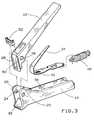
- FIG. 3is an exploded view of the strap tensioning tool of FIG. 1.
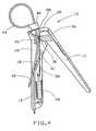
- FIG. 4is a sectional side view of the strap tensioning tool of FIG. 1.
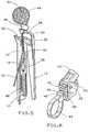
- FIG. 5is a sectional side view of the strap tensioning tool of FIG. 1 shown in the actuated position.
- FIG. 6is a fractional view of the front end of the strap tensioning tool of FIG. 1 shown with a cutter blade moved out of the strap path.
- a cable tie strap tensioning tool embodying the concept of the present inventionis designated generally by the reference numeral 10 in the accompanying drawings.
- strap tensioning tool 10includes a top handle 12 pivotally attached at a front end to a bottom handle 14.
- Bottom handle 14is generally channel-shaped having a floor portion and a pair of vertical side walls.
- the floor of bottom handle 14is provided with an opening 16 that acts as a strap exit passageway.
- the floor of bottom handle 14further includes a frontwardly inclined portion 18 adjacent opening 16 that creates a strap guiding surface for leading a strap end 42 into strap exit opening 16.
- bottom handle 14is further provided with a pair of side wall extension surfaces 20 along its front end. Each side wall extension surface 20 is provided with a pivot engaging aperture 24.
- FIG. 1pivot engaging aperture
- top handle 12is similarly formed having a general channel shape with a floor and a pair of vertical side walls.
- the top and bottom handles 12, 14are connected so that the floor of the channel of top handle 12 faces the floor of the channel of bottom handle 14.
- Top handle 12has pivot pins 26, disposed on each outer side of the side walls of the handle member near the front end, which engage apertures 24 of extended side wall surfaces 20 of bottom handle 14 to allow for the pivotable connection of the two handles.
- the front end of top handle 12also includes a pair of spaced apart pusher surfaces 28 extending downward towards bottom handle 14 and joined at their ends by a transverse bar member.
- the spaced apart pusher surfaces 28 of top handle 12 and extended side wall surfaces 20 of the channel-shaped extended side wall surfaces 20 of the channel-shaped bottom handle 14 along with the respective floor portions of the top and bottom handle membersform a passageway 56 when the top and bottom handles 12, 14 are in engagement.
- the passageway 56 formed between the top and bottom handles 12, 14is disposed to accept and position the strap end 42 of a cable tie 44 that has been inserted through a cable tie head 46 to enclose and secure a bundle 54.
- top and bottom handles 12, 14are pivotally mounted for rotation between a first biased apart position and a second compressed position.
- the pivoting range of top handle 12is limited in the compressed position by a pair of stops 30 disposed on opposing inside surfaces of bottom handle 14 as best seen in FIG. 5. These stops 30 are located at a point that will stop the top handle 12 to prevent pinching of skin of the user.
- the pivoting range of top handle 12 in the biased apart position away from bottom handle 14is also limited by the bottom ends and transverse bar of pusher surfaces 28 abutting an angled front floor portion 32 of bottom handle 14 as can best be seen in FIGS. 3 and 4.
- tensioning tool 10also includes a handle return spring 34 that is situated between top handle 12 and bottom handle 14.
- Return spring 34is formed from a single flat piece of tempered spring steel. Return spring 34 is bent into a general U-shape and is disposed so as to have a leg portion in each of the channel areas of both the top and bottom handles 12, 14, and so that the bent portion is situated around a cam surface 36 formed integrally with the front end of top handle 12. Return spring 34 is engaged with the channels of top and bottom handles 12, 14 in a manner so that they are biased apart. Return spring 34 is further secured by being positioned under a pair of spring guides 38 formed on the inside of the side walls of bottom handle 14. As best seen in FIG. 4, return spring 34 is provided with a plurality of gripper barbs 40 disposed on the underside of return spring 34 below cam surface 36.
- the leading end 42 of the cable tie strap that is intended to be tightenedis inserted into passageway 56 of the front end.
- the userpresses top handle 12 towards bottom handle 14 against the bias of return spring 34 causing top handle 12 to pivot towards bottom handle 14.
- cam surface 36forces gripping barbs 40 into engagement with the leading end of strap 42 by pressing against the floor of bottom handle 14 thereby fixing strap end 42 in position.
- Pusher surfaces 28which are in abutment with cable tie head 46 rotate away from the fixed leading strap end 42 held by gripping barbs 40 as top handle 12 pivots toward bottom handle 14. Therefore, cable tie head 46 is forced along the strap away from the fixed strap end 42 so as to tighten the cable tie 44 around bundle 54.
- handle return spring 34forces the top and bottom handles 12, 14 apart which releases strap end 42 from the grip of barbs 40 and allows for further tightening.
- the excess part of strap end 42is led through strap exit opening 16 by inclined portion 18 of the floor of bottom handle 14.
- a tension limiting spring 48is disposed within the channel of bottom handle 14 and is attached at one end to the back end of bottom handle 14 and at its other end to an end of return spring 34.
- tension limiting spring 48maintains the position of handle return spring 34 and gripper barbs 40 on return spring 34 to hold the leading end of strap 42 in place.
- tension limiting spring 48expands causing the return spring 34 and leading end of strap 42 to move forward along with cable tie head 46 and prevent further tightening as seen in FIG. 5.
- the sides of pusher surfaces 28are further provided with grooves 50 formed on each side which allows for engagement with a slidable metal cutter blade 52.
- Cutter blade 52provides a strap slot having sharp edges around the slot in which the leading end of cable tie strap 42 is passed through.
- Cutter blade 52engages grooves 50 at the front end of top handle 12, and is situated across the front of passageway 56.
- the slot of cutter blade 52is dimensioned to have a height that is smaller than the width of strap 44, so that when the excess strap is ready to be cut off, tool 10 can simply be rotated by the user causing the sharp edges of cutter blade 52 to cut through the strap.
- cutter blade 52is selectively usable since it can be slid upwards in grooves 50 out of the way of the strap as it enters passageway 56.
Landscapes
- Engineering & Computer Science (AREA)
- Mechanical Engineering (AREA)
- Basic Packing Technique (AREA)
Description
- The present invention relates to a strap tensioning and cutting tool, and more particularly to a simple cable tie tensioning tool that includes a spring for limiting the tensioning action of the tool.
- In applications using cable ties and the like, it is important to make sure that the cable ties are properly fastened around the bundle. Since it is usually difficult and inefficient for the user to simply use his hands for tightening the cable tie, strap tensioning tools are used (see e.g. DE-A-2 824 071, which discloses a tool in accordance with the preamble of claim 1). A major problem with most current cable tie strap tensioning tools is that they are complicated hand tools which require a great deal of time, effort, and skill to manufacture and are often difficult to operate. They often include numerous pivoting, bending and sliding members that are not only more difficult to manufacture but can also lead to a higher occurrence of breakdowns or defects of the tools during use. Additionally, while the cable tie must be sufficiently tightened to properly secure the bundle, overtightening can also cause difficulties such as strap failure or other damage. Therefore, it is important to have a simple device that can easily tighten the cable tie tightly around a bundle of wires without over-tightening the strap. It is also frequently desirable to be able to selectively cut off the excess strap from a tightened cable tie using the tightening tool.
- It is therefore an object of the present invention to provide a cable tie strap tensioning tool having reduced complexity.
- It is another object of the present invention to provide a simple cable tie tensioning and cutting tool having the ability to automatically stop tightening upon reaching a desired tension.
- It is yet another object of the present invention to provide a simple cable tie strap tensioning tool that tightens the strap around a bundle by holding the strap end in a fixed position while pushing the cable tie head along the strap in a tightening direction.
- These and other objects, together with the advantages thereof over existing prior art forms, which will become apparent from the following specification are accomplished by means of the strap tensioning tool as defined in the appended claims.
- FIG. 1 is a perspective view of a strap tensioning tool engaged with a cable tie strap embodying the concept of the present invention.
- FIG. 2 is a perspective view of the strap tensioning tool of FIG. 1 in the actuated position.
- FIG. 3 is an exploded view of the strap tensioning tool of FIG. 1.
- FIG. 4 is a sectional side view of the strap tensioning tool of FIG. 1.
- FIG. 5 is a sectional side view of the strap tensioning tool of FIG. 1 shown in the actuated position.
- FIG. 6 is a fractional view of the front end of the strap tensioning tool of FIG. 1 shown with a cutter blade moved out of the strap path.
- A cable tie strap tensioning tool embodying the concept of the present invention is designated generally by the
reference numeral 10 in the accompanying drawings. - As can be seen in FIG. 1,
strap tensioning tool 10 includes atop handle 12 pivotally attached at a front end to abottom handle 14.Bottom handle 14 is generally channel-shaped having a floor portion and a pair of vertical side walls. As can be seen in FIG. 4, the floor ofbottom handle 14 is provided with an opening 16 that acts as a strap exit passageway. The floor ofbottom handle 14 further includes a frontwardlyinclined portion 18adjacent opening 16 that creates a strap guiding surface for leading astrap end 42 intostrap exit opening 16. As best seen in FIG. 3,bottom handle 14 is further provided with a pair of sidewall extension surfaces 20 along its front end. Each sidewall extension surface 20 is provided with a pivotengaging aperture 24. As can be seen in FIG. 4,top handle 12 is similarly formed having a general channel shape with a floor and a pair of vertical side walls. The top andbottom handles top handle 12 faces the floor of the channel ofbottom handle 14.Top handle 12 haspivot pins 26, disposed on each outer side of the side walls of the handle member near the front end, which engageapertures 24 of extendedside wall surfaces 20 ofbottom handle 14 to allow for the pivotable connection of the two handles. The front end oftop handle 12 also includes a pair of spaced apartpusher surfaces 28 extending downward towardsbottom handle 14 and joined at their ends by a transverse bar member. The spaced apartpusher surfaces 28 oftop handle 12 and extendedside wall surfaces 20 of the channel-shaped extendedside wall surfaces 20 of the channel-shaped bottom handle 14 along with the respective floor portions of the top and bottom handle members form apassageway 56 when the top andbottom handles passageway 56 formed between the top andbottom handles strap end 42 of acable tie 44 that has been inserted through acable tie head 46 to enclose and secure abundle 54. - The top and
bottom handles top handle 12 is limited in the compressed position by a pair ofstops 30 disposed on opposing inside surfaces ofbottom handle 14 as best seen in FIG. 5. Thesestops 30 are located at a point that will stop thetop handle 12 to prevent pinching of skin of the user. The pivoting range oftop handle 12 in the biased apart position away frombottom handle 14 is also limited by the bottom ends and transverse bar ofpusher surfaces 28 abutting an angledfront floor portion 32 ofbottom handle 14 as can best be seen in FIGS. 3 and 4. - As seen in FIG. 4,
tensioning tool 10 also includes ahandle return spring 34 that is situated betweentop handle 12 andbottom handle 14. Returnspring 34 is formed from a single flat piece of tempered spring steel.Return spring 34 is bent into a general U-shape and is disposed so as to have a leg portion in each of the channel areas of both the top andbottom handles cam surface 36 formed integrally with the front end oftop handle 12. Returnspring 34 is engaged with the channels of top andbottom handles Return spring 34 is further secured by being positioned under a pair ofspring guides 38 formed on the inside of the side walls ofbottom handle 14. As best seen in FIG. 4, returnspring 34 is provided with a plurality ofgripper barbs 40 disposed on the underside ofreturn spring 34 belowcam surface 36. - In use, the leading
end 42 of the cable tie strap that is intended to be tightened is inserted intopassageway 56 of the front end. The user presses top handle 12 towardsbottom handle 14 against the bias ofreturn spring 34 causingtop handle 12 to pivot towardsbottom handle 14. Astop handle 12approaches bottom handle 14,cam surface 36forces gripping barbs 40 into engagement with the leading end ofstrap 42 by pressing against the floor ofbottom handle 14 thereby fixingstrap end 42 in position.Pusher surfaces 28 which are in abutment withcable tie head 46 rotate away from the fixed leadingstrap end 42 held by grippingbarbs 40 astop handle 12 pivots towardbottom handle 14. Therefore,cable tie head 46 is forced along the strap away from the fixedstrap end 42 so as to tighten the cable tie 44 aroundbundle 54. Whentop handle 12 is released, handlereturn spring 34 forces the top andbottom handles strap end 42 from the grip ofbarbs 40 and allows for further tightening. The excess part ofstrap end 42 is led through strap exit opening 16 byinclined portion 18 of the floor ofbottom handle 14. - In order to prevent overtightening a
tension limiting spring 48 is disposed within the channel ofbottom handle 14 and is attached at one end to the back end ofbottom handle 14 and at its other end to an end ofreturn spring 34. During tensioning, as described above, when the spring force oftension limiting spring 48 is greater than the force required ofpusher surfaces 28 to tightencable tie 44,tension limiting spring 48 maintains the position ofhandle return spring 34 andgripper barbs 40 onreturn spring 34 to hold the leading end ofstrap 42 in place. However, aftercable tie 44 has been tightened to a point where the force required ofpusher surfaces 28 againstcable tie head 46 to movecable tie head 46 along the strap in a tightening direction becomes greater than the restraining force exerted bytension limiting spring 48 onhandle return spring 34,tension limiting spring 48 expands causing thereturn spring 34 and leading end ofstrap 42 to move forward along withcable tie head 46 and prevent further tightening as seen in FIG. 5. - As can be seen in FIG. 3, the sides of
pusher surfaces 28 are further provided withgrooves 50 formed on each side which allows for engagement with a slidablemetal cutter blade 52.Cutter blade 52 provides a strap slot having sharp edges around the slot in which the leading end ofcable tie strap 42 is passed through.Cutter blade 52 engagesgrooves 50 at the front end oftop handle 12, and is situated across the front ofpassageway 56. The slot ofcutter blade 52 is dimensioned to have a height that is smaller than the width ofstrap 44, so that when the excess strap is ready to be cut off,tool 10 can simply be rotated by the user causing the sharp edges ofcutter blade 52 to cut through the strap. As shown in FIG. 6,cutter blade 52 is selectively usable since it can be slid upwards ingrooves 50 out of the way of the strap as it enterspassageway 56. - While the particular embodiment of the present invention has been shown and described, it will be obvious to those skilled in the art that changes and modifications may be made without departing from the invention in its broader aspects. The matter set forth in the foregoing description and accompanying drawings is offered by way of illustration only and not as a limitation. The actual scope of the invention is intended to be defined in the following claims when viewed in their proper perspective based on the prior art.
Claims (10)
- A strap tensioning tool (10) for tightening a cable tie having a strap (44) and a locking head (46) around a bundle (54) comprising a bottom handle (14) and a top handle (12) pivotally attached at a front end to a front end of the bottom handle, a passageway (56) formed between the top and bottom handles at the front end, disposed to accept and position a strap end (42) of the cable tie that has been inserted through the cable tie locking head (46), a flexible return member (34) engaged and situated between the top and bottom handles so as to bias them apart, pushing means integral with the top handle (12) including at least one pusher surface (28) located at the front end of the top handle (12) that pushes the locking head (46) of the cable tie away from the held strap end as the top handle (12) rotates towards the bottom handle (14),
characterized in that
it includes a cam surface (36) integral with the top handle (12) and disposed so as to be facing the bottom handle (14), and barb means (40) disposed on the flexible return member (34) adjacent the cam surface (36), the cam surface (36) forcing the barb means (40) into engagement with the strap end by pressing against the bottom handle (14) as the top handle (12) and the bottom handle (14) rotate towards each other, thereby preventing the strap end from movement. - A strap tensioning tool according to claim 1, wherein the strap gripping barb means comprises at least one barb (40) formed on the handle return member (34).
- A strap tensioning tool according to claim 1 or 2, further including means for automatically limiting the tightening of the cable tie around the bundle (54) to prevent overtightening.
- A strap tensioning tool in accordance with claim 3, wherein the tension limiting means includes a tension limiting spring (48) attached at one end to the flexible return member (34) and at the other end to the bottom handle (14).
- A strap tensioning tool according to one of the claims 1 to 4, further comprising cutting means for cutting off the excess strap end at a point near the cable tie head (46) after tightening.
- A strap tensioning tool according to claim 5, wherein the cutting means includes a cutter blade (52) having a strap receiving slot.
- A strap tensioning tool according to one of the claims 1 to 6 wherein the bottom handle (14) is generally channel-shaped.
- A strap tensioning tool according to claim 7, wherein the bottom handle (14) further includes a strap exit passageway.
- A strap tensioning tool according to claim 6, wherein the cutter blade (52) is selectively attachable to the top handle (12) at a point near the pusher surface (12).
- A strap tensioning tool according to claim 9, wherein the cutter blade (52) is movable so that it is selectively engageable with the strap end as the strap end is inserted into the passageway between the top and bottom handles (12, 14).
Applications Claiming Priority (2)
| Application Number | Priority Date | Filing Date | Title |
|---|---|---|---|
| US08/103,015US5386856A (en) | 1993-08-06 | 1993-08-06 | Tension limiting strap tool |
| US103015 | 1993-08-06 |
Publications (2)
| Publication Number | Publication Date |
|---|---|
| EP0637544A1 EP0637544A1 (en) | 1995-02-08 |
| EP0637544B1true EP0637544B1 (en) | 1997-05-07 |
Family
ID=22292906
Family Applications (1)
| Application Number | Title | Priority Date | Filing Date |
|---|---|---|---|
| EP94111409AExpired - LifetimeEP0637544B1 (en) | 1993-08-06 | 1994-07-21 | Strap tensioning tool |
Country Status (6)
| Country | Link |
|---|---|
| US (1) | US5386856A (en) |
| EP (1) | EP0637544B1 (en) |
| JP (1) | JPH0769318A (en) |
| AU (1) | AU669299B2 (en) |
| CA (1) | CA2127517A1 (en) |
| DE (1) | DE69403033T2 (en) |
Families Citing this family (16)
| Publication number | Priority date | Publication date | Assignee | Title |
|---|---|---|---|---|
| IT1286370B1 (en)* | 1996-10-31 | 1998-07-08 | Thomas & Betts Corp | AUTOMATIC TOOL FOR INSTALLING CABLE TIES |
| GB2360554A (en)* | 2000-03-21 | 2001-09-26 | Phillip Fields Hayward | A hand tool for tightening a strap around a rubber gaitor for a motor vehicle joint |
| US6421896B1 (en) | 2000-11-20 | 2002-07-23 | Neal (Mitz) K. Beyer | Tool for removing and reinstalling a valve |
| US6711930B2 (en) | 2001-06-01 | 2004-03-30 | Telect, Inc. | Fiber optic cable trough component notching system |
| US8500739B2 (en)* | 2007-04-06 | 2013-08-06 | DePuy Synthes Products, LLC | Securing device to secure fixation devices to bone portions |
| US20100083469A1 (en)* | 2008-10-06 | 2010-04-08 | Welker, Inc. | Reusable carrying handle with a cable tie |
| CA2757699A1 (en)* | 2009-03-19 | 2010-09-23 | Figure 8 Surgical, Inc. | Systems and methods for sternum repair |
| US8460295B2 (en) | 2009-03-19 | 2013-06-11 | Figure 8 Surgical, Inc. | Systems and methods for sternum repair |
| WO2011116379A2 (en) | 2010-03-19 | 2011-09-22 | Mcclelan William T | Knotless locking tissue fastening system and method |
| BRPI1002494B1 (en)* | 2010-07-12 | 2015-08-18 | João Bosco De Oliveira | Shear with tensioning device |
| WO2012174562A1 (en) | 2011-06-17 | 2012-12-20 | Figure 8 Surgical, Inc. | Sternum band tensioner device, system and method |
| WO2015167920A1 (en)* | 2014-04-30 | 2015-11-05 | DePuy Synthes Products, Inc. | Tensioning instrument and related bone fixation systems |
| CN108791998B (en)* | 2018-06-27 | 2020-01-21 | 芜湖博康机电有限公司 | Strapping gun |
| JP7220408B2 (en)* | 2019-07-29 | 2023-02-10 | アラム株式会社 | Cable tie cutting device |
| JP7680729B2 (en)* | 2020-06-29 | 2025-05-21 | 合同会社ブレスト工業研究所 | Cable tie excess length cutting tool |
| DE102021102704A1 (en) | 2021-02-05 | 2022-08-11 | Hua Wei Industrial Co., Ltd. | CABLE TIE TOOL |
Family Cites Families (10)
| Publication number | Priority date | Publication date | Assignee | Title |
|---|---|---|---|---|
| US3169560A (en)* | 1962-03-08 | 1965-02-16 | Panduit Corp | Binder strap tool |
| US3993109A (en)* | 1976-01-16 | 1976-11-23 | Thomas & Betts Corporation | Strap tightening and severing tool |
| FR2400995A1 (en)* | 1977-06-02 | 1979-03-23 | Legrand Sa | TRACTION AND CUTTING PLIERS FOR STRIPES, IN PARTICULAR THAT OF A CLAMP COLLAR |
| FR2416092A1 (en)* | 1978-02-01 | 1979-08-31 | Usinage Tubes Pour Electr | AUTOMATIC DEVICE FOR INSTALLING RACK TYPE CLAMPS |
| US4321952A (en)* | 1980-01-21 | 1982-03-30 | American Casting & Mfg. Corporation | Strap tightening hand tool |
| US4602418A (en)* | 1982-08-09 | 1986-07-29 | Dennison Manufacturing Company | Cable tie installation tool |
| FR2585610B1 (en)* | 1985-07-30 | 1989-06-16 | Legrand Sa | TRACTION AND CUTTING PLIERS FOR LANYARD, PARTICULARLY FOR CLAMP |
| US4947901A (en)* | 1989-02-06 | 1990-08-14 | Malco Products, Inc. | Strap tensioning and cut off tool |
| US5048575A (en)* | 1989-02-06 | 1991-09-17 | Malco Products, Inc. | Strap tensioning and cut off tool |
| US5065798A (en)* | 1991-01-28 | 1991-11-19 | Panduit Corp. | Stretched strap cable tie tensioning and severing tool |
- 1993
- 1993-08-06USUS08/103,015patent/US5386856A/ennot_activeExpired - Lifetime
- 1994
- 1994-07-06CACA002127517Apatent/CA2127517A1/ennot_activeAbandoned
- 1994-07-21DEDE69403033Tpatent/DE69403033T2/ennot_activeExpired - Fee Related
- 1994-07-21EPEP94111409Apatent/EP0637544B1/ennot_activeExpired - Lifetime
- 1994-07-22JPJP6171243Apatent/JPH0769318A/ennot_activeWithdrawn
- 1994-08-03AUAU68883/94Apatent/AU669299B2/ennot_activeCeased
Also Published As
| Publication number | Publication date |
|---|---|
| DE69403033T2 (en) | 1997-12-04 |
| AU6888394A (en) | 1995-02-16 |
| CA2127517A1 (en) | 1995-02-07 |
| DE69403033D1 (en) | 1997-06-12 |
| JPH0769318A (en) | 1995-03-14 |
| US5386856A (en) | 1995-02-07 |
| EP0637544A1 (en) | 1995-02-08 |
| AU669299B2 (en) | 1996-05-30 |
Similar Documents
| Publication | Publication Date | Title |
|---|---|---|
| EP0637544B1 (en) | Strap tensioning tool | |
| EP0353011B1 (en) | Tool for tightening cable ties | |
| EP0655298B1 (en) | Bar clamp | |
| US8365418B2 (en) | Cable tie removal tool | |
| US5129158A (en) | Plastic pipe cutter | |
| GB2304366A (en) | Belt and buckle assembly | |
| US4390047A (en) | Tool for strap tensioning and cutting | |
| WO2000069744A1 (en) | Cable tie and cable tie installation tool | |
| US20090188118A1 (en) | Tool for Cutting Tie Wraps | |
| EP0121878B1 (en) | Cable banding machine | |
| NL193198C (en) | Clamp band, applicable as a hose clamp. | |
| JPH03111228A (en) | Fitting tool of ball-lock type bandling materials and its application | |
| US4335477A (en) | Cable tie installing and releasing tool | |
| US4763700A (en) | Binding tool | |
| US5660315A (en) | Line guide and gripping means for staplers | |
| EP0303723B1 (en) | Binding tool | |
| US20020073814A1 (en) | Cutting tool with curved blades for cutting a tie wrap | |
| US4091511A (en) | Band tightening and securing tool | |
| EP1338513A1 (en) | Banding tool | |
| GB2385294A (en) | Improvements to a banding tool | |
| EP0070081B1 (en) | Luggage binder for a bicycle or like vehicle | |
| EP1409205B1 (en) | Tool for applying clips | |
| JPH043933Y2 (en) | ||
| JPH043937Y2 (en) | ||
| EP0336020A1 (en) | Apparatus for sealing of bands |
Legal Events
| Date | Code | Title | Description |
|---|---|---|---|
| PUAI | Public reference made under article 153(3) epc to a published international application that has entered the european phase | Free format text:ORIGINAL CODE: 0009012 | |
| AK | Designated contracting states | Kind code of ref document:A1 Designated state(s):DE FR GB IT | |
| 17P | Request for examination filed | Effective date:19950807 | |
| 17Q | First examination report despatched | Effective date:19951103 | |
| GRAG | Despatch of communication of intention to grant | Free format text:ORIGINAL CODE: EPIDOS AGRA | |
| GRAH | Despatch of communication of intention to grant a patent | Free format text:ORIGINAL CODE: EPIDOS IGRA | |
| GRAH | Despatch of communication of intention to grant a patent | Free format text:ORIGINAL CODE: EPIDOS IGRA | |
| GRAA | (expected) grant | Free format text:ORIGINAL CODE: 0009210 | |
| AK | Designated contracting states | Kind code of ref document:B1 Designated state(s):DE FR GB IT | |
| ET | Fr: translation filed | ||
| REF | Corresponds to: | Ref document number:69403033 Country of ref document:DE Date of ref document:19970612 | |
| PLBE | No opposition filed within time limit | Free format text:ORIGINAL CODE: 0009261 | |
| STAA | Information on the status of an ep patent application or granted ep patent | Free format text:STATUS: NO OPPOSITION FILED WITHIN TIME LIMIT | |
| 26N | No opposition filed | ||
| PGFP | Annual fee paid to national office [announced via postgrant information from national office to epo] | Ref country code:GB Payment date:19980624 Year of fee payment:5 | |
| PGFP | Annual fee paid to national office [announced via postgrant information from national office to epo] | Ref country code:FR Payment date:19980629 Year of fee payment:5 | |
| PGFP | Annual fee paid to national office [announced via postgrant information from national office to epo] | Ref country code:DE Payment date:19980729 Year of fee payment:5 | |
| PG25 | Lapsed in a contracting state [announced via postgrant information from national office to epo] | Ref country code:GB Free format text:LAPSE BECAUSE OF NON-PAYMENT OF DUE FEES Effective date:19990721 | |
| PG25 | Lapsed in a contracting state [announced via postgrant information from national office to epo] | Ref country code:FR Free format text:THE PATENT HAS BEEN ANNULLED BY A DECISION OF A NATIONAL AUTHORITY Effective date:19990731 | |
| GBPC | Gb: european patent ceased through non-payment of renewal fee | Effective date:19990721 | |
| PG25 | Lapsed in a contracting state [announced via postgrant information from national office to epo] | Ref country code:DE Free format text:LAPSE BECAUSE OF NON-PAYMENT OF DUE FEES Effective date:20000503 | |
| REG | Reference to a national code | Ref country code:FR Ref legal event code:ST | |
| PG25 | Lapsed in a contracting state [announced via postgrant information from national office to epo] | Ref country code:IT Free format text:LAPSE BECAUSE OF NON-PAYMENT OF DUE FEES;WARNING: LAPSES OF ITALIAN PATENTS WITH EFFECTIVE DATE BEFORE 2007 MAY HAVE OCCURRED AT ANY TIME BEFORE 2007. THE CORRECT EFFECTIVE DATE MAY BE DIFFERENT FROM THE ONE RECORDED. Effective date:20050721 |