EP0636956B1 - Method of data loading - Google Patents
Method of data loadingDownload PDFInfo
- Publication number
- EP0636956B1 EP0636956B1EP94110920AEP94110920AEP0636956B1EP 0636956 B1EP0636956 B1EP 0636956B1EP 94110920 AEP94110920 AEP 94110920AEP 94110920 AEP94110920 AEP 94110920AEP 0636956 B1EP0636956 B1EP 0636956B1
- Authority
- EP
- European Patent Office
- Prior art keywords
- time
- automation system
- updating
- technical
- update
- Prior art date
- Legal status (The legal status is an assumption and is not a legal conclusion. Google has not performed a legal analysis and makes no representation as to the accuracy of the status listed.)
- Expired - Lifetime
Links
Images

Classifications
- G—PHYSICS
- G06—COMPUTING OR CALCULATING; COUNTING
- G06F—ELECTRIC DIGITAL DATA PROCESSING
- G06F11/00—Error detection; Error correction; Monitoring
- G06F11/07—Responding to the occurrence of a fault, e.g. fault tolerance
- G06F11/16—Error detection or correction of the data by redundancy in hardware
- G06F11/20—Error detection or correction of the data by redundancy in hardware using active fault-masking, e.g. by switching out faulty elements or by switching in spare elements
- G06F11/2053—Error detection or correction of the data by redundancy in hardware using active fault-masking, e.g. by switching out faulty elements or by switching in spare elements where persistent mass storage functionality or persistent mass storage control functionality is redundant
- G06F11/2056—Error detection or correction of the data by redundancy in hardware using active fault-masking, e.g. by switching out faulty elements or by switching in spare elements where persistent mass storage functionality or persistent mass storage control functionality is redundant by mirroring
- G06F11/2082—Data synchronisation
- G—PHYSICS
- G05—CONTROLLING; REGULATING
- G05B—CONTROL OR REGULATING SYSTEMS IN GENERAL; FUNCTIONAL ELEMENTS OF SUCH SYSTEMS; MONITORING OR TESTING ARRANGEMENTS FOR SUCH SYSTEMS OR ELEMENTS
- G05B19/00—Programme-control systems
- G05B19/02—Programme-control systems electric
- G05B19/04—Programme control other than numerical control, i.e. in sequence controllers or logic controllers
- G05B19/042—Programme control other than numerical control, i.e. in sequence controllers or logic controllers using digital processors
- G05B19/0428—Safety, monitoring
- G—PHYSICS
- G06—COMPUTING OR CALCULATING; COUNTING
- G06F—ELECTRIC DIGITAL DATA PROCESSING
- G06F11/00—Error detection; Error correction; Monitoring
- G06F11/07—Responding to the occurrence of a fault, e.g. fault tolerance
- G06F11/16—Error detection or correction of the data by redundancy in hardware
- G06F11/1658—Data re-synchronization of a redundant component, or initial sync of replacement, additional or spare unit
- G—PHYSICS
- G06—COMPUTING OR CALCULATING; COUNTING
- G06F—ELECTRIC DIGITAL DATA PROCESSING
- G06F8/00—Arrangements for software engineering
- G06F8/60—Software deployment
- G06F8/65—Updates
- G06F8/656—Updates while running
- G—PHYSICS
- G05—CONTROLLING; REGULATING
- G05B—CONTROL OR REGULATING SYSTEMS IN GENERAL; FUNCTIONAL ELEMENTS OF SUCH SYSTEMS; MONITORING OR TESTING ARRANGEMENTS FOR SUCH SYSTEMS OR ELEMENTS
- G05B2219/00—Program-control systems
- G05B2219/20—Pc systems
- G05B2219/24—Pc safety
- G05B2219/24185—After repair, update redundant system during non critical periods
- G—PHYSICS
- G06—COMPUTING OR CALCULATING; COUNTING
- G06F—ELECTRIC DIGITAL DATA PROCESSING
- G06F11/00—Error detection; Error correction; Monitoring
- G06F11/07—Responding to the occurrence of a fault, e.g. fault tolerance
- G06F11/16—Error detection or correction of the data by redundancy in hardware
- G06F11/1629—Error detection by comparing the output of redundant processing systems
- G06F11/1633—Error detection by comparing the output of redundant processing systems using mutual exchange of the output between the redundant processing components
- G—PHYSICS
- G06—COMPUTING OR CALCULATING; COUNTING
- G06F—ELECTRIC DIGITAL DATA PROCESSING
- G06F11/00—Error detection; Error correction; Monitoring
- G06F11/07—Responding to the occurrence of a fault, e.g. fault tolerance
- G06F11/16—Error detection or correction of the data by redundancy in hardware
- G06F11/20—Error detection or correction of the data by redundancy in hardware using active fault-masking, e.g. by switching out faulty elements or by switching in spare elements
- G06F11/202—Error detection or correction of the data by redundancy in hardware using active fault-masking, e.g. by switching out faulty elements or by switching in spare elements where processing functionality is redundant
- G06F11/2038—Error detection or correction of the data by redundancy in hardware using active fault-masking, e.g. by switching out faulty elements or by switching in spare elements where processing functionality is redundant with a single idle spare processing component
Definitions
- the present inventionrelates to an update method for an additional automation system that connects to at least one an initial automation system, by means of of a processed program a technical process or a technical system controlling automation system is coupled.
- Redundant automation systemsare widely used.
- the automation systemsare usually simple or double redundancy, i.e. there will be two or three automation systems to control one and the same technical Process or one and the same technical system used.
- that a subsystemfails and the technical system or the technical process through the remaining Subsystem (initial automation system) or the remaining ones Subsystems is managed.
- After the exchange or the repair of the failed subsystem Subsystemback to the at least one initial automation system be coupled. So far this is happening e.g. in that this is the technical system at the moment initial automation system controlling the program execution interrupts the necessary operating data from the beginning to the Additional automation system will be transferred and then the initial and additional automation system die Continue program execution and so lead together of the technical system.
- EP-A-0 460 308describes an update procedure for the database of a redundant processor in a process control system specified.
- the data of the first processor systemdue to the control engineering carried out by it Process subject to permanent change are periodically transferred to the redundant processor, so that in the event of a failure of the first processor can take over process control.
- the disadvantageis in this context, however, that after each control cycle performed data transfer the cycle time of the control cycles increases so that the time taken for the reaction to increase accordingly on events occurring in the process, increased.
- the object of the present inventionis therefore to to provide an update process in which these disadvantages do not occur.
- the taskis carried out by means of an update procedure for an additional automation system, that to one of at least one Initial automation system existing, by means of a processed Program a technical process or a automation system controlling the technical system is, the updating process while maintaining the Control of the technical process or the technical system is feasible, with a time-uncritical for updating State of the technical process or technical System is awaited and the updating is complete during this non-time critical state, solved by that the initial automation system data configurations non-time-critical states are specified so that non-time critical states of the initial automation system are recognizable.
- FIG 1is a - only shown schematically - technical Appendix 1, in which a technical process takes place, by the initial automation system 2 controlled.
- the automation system 2is briefly referred to below as the initial system.
- the automation system 2'as Zu sentence system.
- the starting systempoints to the control of the technical system 1 2 a processor 3, which is used to control the technical Appendix 1 runs a program that is in memory 4 is saved.
- the control of the technical Plant 1is carried out via plant interface 5.
- the additional system 2 'consists essentially of the same Components: processor 3 ', memory 4' and Plant interface 5 '.
- the starting systems 2are the data configurations non-time-critical states and the associated time periods, during which the reaction to process changes is not time-critical is specified.
- the starting system 2can current process data with the data configurations less time critical Compare states and so non-time critical Detect states. If such a condition is recognized the associated time period during which the response to changes in state is not time-critical, with compared to the update time. If the duration of the non-time critical State exceeds the update time, the activates Processor 3 via the control line 6 the communication interface 7. This then calls the bus 8 to be updated Data from the main memory 4 and transfers it via the communication line 9 to the communication interface 7 'of the additional system 2'. This in turn saves them in the working memory 4 'and signals this End of the update process the processor 3 '. Of this At the moment both automation systems 2, 2 'are in the Able to take control of the technical system immediately (so-called hot stand by operation).
- Hhexadecimal
- the memory rangefrom 3400H to 3500H.
- the storage area of 3300H to 3400Hwith falling address cycle
- 3500H to 3600Hare transmitted (with increasing address throughput).
- the Initial system 2input signals from the technical system read in and output signals to the technical system 1 spent.
- the additional system 2 'may during the Of course, neither the program nor Execute write peripheral access. Read only Peripheral access is permitted. The execution of reading peripheral access is even an advantage since this inevitably updates the additional system 2 '.
- the memory area to be updatedshould transferred only once from the starting system 2 to the additional system 2 ' and otherwise the input signals from the technical system 1 from the additional system 2 ' become.
- other signalsalso change, for example Counter and timer values as well as the output signals.
- the present inventionprovides two possible procedures provided. If the Communication interfaces 7, 7 'and the communication line 9 are efficient, the following will be advantageous Procedure carried out:
- a transmission addressis initially the same as the start address set, in this example the same 3000H.
- the first 100H bytes from start system 2 to additional system 2 ' transferis increased by the number the transmitted data increased, in the present case so set to 3100H.
- the transfer addressis increased by the number the transmitted data increased, in the present case so set to 3100H.
- the time until the next time slice is reachedare all write accesses to the memory area from 3000H to 3100H which the initial system 2 executes.
- Youwill use the communication interface 7 immediately reported to the communication interface 7 ' the addresses and the values of the newly written data in the Additional memory 10 'filed.
- the additional memory 10 'is in in this case organized as a circulation buffer.
- the processor 3 'is therefore able to immediately reuse the circulation buffer 10 ' read out and thus the already opened memory area the RAM 4 'to update or on the keep current status.
- each 100H bytes from start system 2 to additional system 2 ' transferThere they are first stored in the additional memory 10 ' saved.
- the program cycle between two Time slicesare those written into the additional memory 10 ' Data with the corresponding data in the working memory 4 'compared and then in the working memory 4 'registered.
- the processornotes this 3 'whether the data is the same. If the dates are the same, the value of the counter 11 'is increased by one. Otherwise the counter 11 'is set to the value zero.
- the updateruns take place alternately, if necessary with increasing and decreasing address flow.
- the Updatingis considered to have been performed if during a given Number of successive time slices for all Comparative equality was determined, i.e. the transferred data differs from that already in the working memory 4 no differentiate between the data.
- test variablescan, for example a checksum or a signature.
- the determined Test variablesare via the communication interfaces 7, 7 'exchanged and compared with each other. Are the If the test parameters are the same, the update is considered finished. Otherwise the counter 11 'is set to zero and a new one Update process made.
Landscapes
- Engineering & Computer Science (AREA)
- Theoretical Computer Science (AREA)
- Physics & Mathematics (AREA)
- General Engineering & Computer Science (AREA)
- General Physics & Mathematics (AREA)
- Software Systems (AREA)
- Quality & Reliability (AREA)
- Automation & Control Theory (AREA)
- Computer Security & Cryptography (AREA)
- Hardware Redundancy (AREA)
- Debugging And Monitoring (AREA)
- Stored Programmes (AREA)
- Communication Control (AREA)
- Oscillators With Electromechanical Resonators (AREA)
- Transition And Organic Metals Composition Catalysts For Addition Polymerization (AREA)
- Devices For Checking Fares Or Tickets At Control Points (AREA)
- Retry When Errors Occur (AREA)
Abstract
Description
Translated fromGermanDie vorliegende Erfindung betrifft ein Aufdatverfahren fürein Zusatzautomatisierungssystem, das an ein aus mindestenseinem Anfangsautomatisierungssystem bestehenden, mittelseines abgearbeiteten Programms einen technischen Prozeßbzw. eine technische Anlage steuernden Automatisierungssystemangekoppelt ist.The present invention relates to an update method foran additional automation system that connects to at least onean initial automation system, by means ofof a processed program a technical processor a technical system controlling automation systemis coupled.
Redundante Automatisierungssysteme sind weit verbreitet.Meist sind die Automatisierungssysteme dabei einfach oderdoppelt redundant, d.h. es werden zwei bzw. drei Automatisierungssystemezur Steuerung ein und desselben technischenProzesses bzw. ein und derselben technischen Anlageverwendet. Bei einer derartigen Konfiguration kann es vorkommen,daß ein Teilsystem ausfällt und die technische Anlagebzw. der technische Prozeß durch das verbleibendeTeilsystem (Anfangsautomatisierungssystem) bzw. die verbleibendenTeilsysteme geführt wird. Nach dem Austauschbzw. der Reparatur des ausgefallenen Teilsystems muß diesesTeilsystem wieder an das mindestens eine Anfangsautomatisierungssystemangekoppelt werden. Bisher geschieht diesz.B. dadurch, daß das die technische Anlage momentansteuernde Anfangsautomatisierungssystem die Programmabarbeitungunterbricht, die nötigen Betriebsdaten vom AnfangszumZusatzautomatisierungssystem übertragen werden und sodanndas Anfangs- und das Zusatzautomatisierungssystem dieProgrammabarbeitung fortsetzen und so gemeinsam die Führungder technischen Anlage übernehmen.Redundant automation systems are widely used.The automation systems are usually simple ordouble redundancy, i.e. there will be two or three automation systemsto control one and the same technicalProcess or one and the same technical systemused. With such a configuration,that a subsystem fails and the technical systemor the technical process through the remainingSubsystem (initial automation system) or the remaining onesSubsystems is managed. After the exchangeor the repair of the failed subsystemSubsystem back to the at least one initial automation systembe coupled. So far this is happeninge.g. in that this is the technical system at the momentinitial automation system controlling the program executioninterrupts the necessary operating data from the beginning to theAdditional automation system will be transferred and thenthe initial and additional automation system dieContinue program execution and so lead togetherof the technical system.
Diese Vorgehensweise ist insofern nicht optimal, als währenddes Aufdatens eine Kontrolle der technischen Anlagenicht gewährleistet ist. Andererseits kann es unter Umständen schwierig, gefährlich und zeitaufwendig sein, eineAnlage herunterzufahren und später wieder zu starten.This approach is not optimal insofar as duringcontrol of the technical systemis not guaranteed. On the other hand, under certain circumstancesdifficult, dangerous and time consuming, oneShut down the system and restart it later.
Aus der EP-A-0 460 308 ist ein Aufdatverfahren für den Datenbestandeines redundanten Prozessors in einem Prozeßsteuersystemangegeben. Dabei werden die Daten des ersten Prozessorsystems,die aufgrund des von diesem durchgeführten steuerungstechnischenProzesses permanenten Veränderung unterworfensind, periodisch an den redundanten Prozessors übertragen,so daß dieser im Falle eines Ausfalls des ersten Prozessorsdie Prozeßsteuerung übernehmen kann. Von Nachteil ist indiesem Zusammenhang jedoch, daß der nach jedem Steuerzyklusdurchgeführte Datentransfer die Zykluszeit der Steuerzyklenerhöht, so daß sich entsprechend die Zeit, die bis zur Reaktionauf im Prozeß auftretende Ereignisse verstreicht, erhöht.EP-A-0 460 308 describes an update procedure for the databaseof a redundant processor in a process control systemspecified. The data of the first processor system,due to the control engineering carried out by itProcess subject to permanent changeare periodically transferred to the redundant processor,so that in the event of a failure of the first processorcan take over process control. The disadvantage is inthis context, however, that after each control cycleperformed data transfer the cycle time of the control cyclesincreases so that the time taken for the reaction to increase accordinglyon events occurring in the process, increased.
Die Aufgabe der vorliegenden Erfindung besteht folglich darin,ein Aufdatverfahren zur Verfügung zu stellen, bei demdiese Nachteile nicht auftreten.The object of the present invention is therefore toto provide an update process in whichthese disadvantages do not occur.
Die Aufgabe wird mittels eines Aufdatverfahrens für ein Zusatzautomatisierungssystem,das an ein aus mindestens einemAnfangsautomatisierungssystem bestehendes, mittels eines abgearbeitetenProgramms einen technischen Prozeß bzw. einetechnische Anlage steuerndes Automatisierungssystem angekoppeltist, wobei das Aufdatverfahren unter Beibehaltung derSteuerung des technischen Prozesses bzw. der technischen Anlagedurchführbar ist, wobei zum Aufdaten ein zeitunkritischerZustand des technischen Prozesses bzw. der technischenAnlage abgewartet wird und wobei das Aufdaten vollständigwährend dieses zeitunkritischen Zustands erfolgt, dadurch gelöst,daß dem Anfangsautomatisierungssystem Datenkonfigurationenzeitunkritischer Zustände vorgegeben werden, so daß zeitunkritische Zustände des Anfangsautomatisierungssystemserkennbar sind.The task is carried out by means of an update procedure for an additional automation system,that to one of at least oneInitial automation system existing, by means of a processedProgram a technical process or aautomation system controlling the technical systemis, the updating process while maintaining theControl of the technical process or the technical systemis feasible, with a time-uncritical for updatingState of the technical process or technicalSystem is awaited and the updating is completeduring this non-time critical state, solved bythat the initial automation system data configurationsnon-time-critical states are specified so thatnon-time critical states of the initial automation systemare recognizable.
Ferner ist es möglich, daß das Aufdaten in Zeitscheiben erfolgt,die in die Programmabarbeitung des Anfangsautomatisierungssystemseingefügt werden.It is also possible that the update takes place in time slices,in the program execution of the initial automation systembe inserted.
Weitere Vorteile und Einzelheiten ergeben sich aus der nachfolgendenBeschreibung eines Ausführungsbeispiels, anhand derZeichnungen und in Verbindung mit den weiteren Unteransprüchen.Dabei zeigen:
Gemäß FIG 1 wird eine - nur schematisch dargestellte - technischeAnlage 1, in der ein technischer Prozeß abläuft, durchdas Anfangsautomatisierungssystem 2 gesteuert. Das Automatisierungssystem2 wird im folgenden kurz als Anfangssystem bezeichnet.Ebenso wird das Automatisierungssystem 2' als Zusatzsystem bezeichnet.According to FIG 1 is a - only shown schematically - technicalAppendix 1, in which a technical process takes place, bythe initial automation system 2 controlled. The automation system2 is briefly referred to below as the initial system.Likewise, the automation system 2 'as Zusentence system.
Zur Steuerung der technischen Anlage 1 weist das Anfangssystem2 einen Prozessor 3 auf, der zur Steuerung der technischenAnlage 1 ein Programm abarbeitet, das im Arbeitsspeicher4 abgespeichert ist. Die Steuerung der technischenAnlage 1 erfolgt dabei über die Anlagenschnittstelle 5.The starting system points to the control of the technical system 12 a
Das Zusatzsystem 2' besteht im wesentlichen aus den gleichenKomponenten: Prozessor 3', Arbeitsspeicher 4' undAnlagenschnittstelle 5'.The additional system 2 'consists essentially of the sameComponents: processor 3 ', memory 4' andPlant interface 5 '.
Im vorliegenden Fall ist angenommen, daß das Anfangssystem2 die technische Anlage 1 ausschließlich steuert und daßdas Zusatzsystem 2' an das Anfangssystem 2 angekoppelt werdensoll, um bei einem Ausfall des Anfangssystems 2 dieSteuerung der technischen Anlage 1 sofort übernehmen zukönnen. Hierzu muß nicht nur das Programm im Arbeitsspeicher4' identisch mit dem Programm im Arbeitsspeicher 4sein, sondern es müssen auch die Prozeßdaten in den beidenAutomatisierungssystemen 2, 2' übereinstimmen.In the present case it is assumed that the initial system2 controls the technical system 1 exclusively and thatthe additional system 2 'are coupled to the starting system 2in order to avoid the failure of the initial system 2Control of technical system 1 take over immediatelycan. To do this, it is not only the program that has to be in the working memory4 'identical to the program in the working memory 4but also the process data in the twoAutomation systems 2, 2 'match.
Um diese Übereinstimmung der Prozeßdaten aufdatstoßfrei zuerreichen, wird gemäß einer Ausführungsform der vorliegendenErfindung im Arbeitsspeicher 4 abgelegt, welche Aufdatzeitbenötigt wird, um das Aufdaten des Zusatzsystems 2'durchführen zu können. Diese Aufdatzeit ist selbstverständlichvom Umfang der aufzudatenden Daten und der Leistungsfähigkeitder Kommunikation zwischen den Automatisierungssystemen2, 2' abhängig.In order to ensure that the process data match without any gapsis achieved according to an embodiment of the presentInvention stored in memory 4, which update timeis required to update the additional system 2 'to be able to perform. This update time is a matter of coursethe scope of the data to be updated and the performancecommunication between the automation systems2, 2 'dependent.
Ferner sind dem Anfangssystem 2 die Datenkonfigurationenzeitunkritischer Zustände und die zugehörigen Zeitdauern,während derer das Reagieren auf Prozeßänderungen zeitunkritischist, vorgegeben. Dadurch kann das Anfangssystem 2 diemomentanen Prozeßdaten mit den Datenkonfigurationen zeitunkritischerZustände vergleichen und so zeitunkritischeZustände erkennen. Wenn ein derartiger Zustand erkanntworden ist, wird die zugehörige Zeitdauer, während derer die Reaktion auf Zustandsänderungen zeitunkritisch ist, mitder Aufdatzeit verglichen. Wenn die Dauer des zeitunkritischenZustands die Aufdatzeit übersteigt, aktiviert derProzessor 3 über die Steuerleitung 6 die Kommunikationsschnittstelle7. Diese ruft dann über den Bus 8 die aufzudatendenDaten aus dem Arbeitsspeicher 4 ab und überträgtsie über die Kommunikationsleitung 9 an die Kommunikationsschnittstelle7' des Zusatzsystems 2'. Dieses wiederumspeichert sie im Arbeitsspeicher 4' ab und signalisiert dasBeenden des Aufdatvorgangs dem Prozessor 3'. Von diesemMoment an sind beide Automatisierungssysteme 2, 2' in derLage, sofort die Steuerung der technischen Anlage zu übernehmen(sogenannter hot stand by-Betrieb).Furthermore, the starting systems 2 are the data configurationsnon-time-critical states and the associated time periods,during which the reaction to process changes is not time-criticalis specified. As a result, the starting system 2 cancurrent process data with the data configurations less time criticalCompare states and so non-time criticalDetect states. If such a condition is recognizedthe associated time period during whichthe response to changes in state is not time-critical, withcompared to the update time. If the duration of the non-time criticalState exceeds the update time, the activates
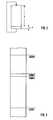
Obenstehendes Verfahren ist optimal, wenn ein zeitunkritischerZustand der technischen Anlage existiert, dessenDauer die Aufdatzeit übersteigt. Wenn dagegen kein derartigerZustand existiert, muß in Zeitscheiben aufgedatetwerden, die zyklisch in die Programmbearbeitung eingefügtwerden. Hierzu ist zu erwähnen, daß gemäß FIG 2 die Programmabarbeitungbei Automatisierungsgeräten in der Regelzyklisch erfolgt. Die Programmzykluszeit ist dabei in FIG 2mit T bezeichnet. Am Ende eines Programmzyklus wird nun inkleinen Zeitscheiben, deren Dauer t beträgt, das Programmzusatzsystem2' nach und nach aufgedatet. Die dadurch entstehendeVerlängerung der Programmzykluszeit T ist dabeivernachlässigbar. Anstelle der Einfügung nur einer Zeitscheibepro Zeitzyklus ist es selbstverständlich auch möglich,mehrere Zeitscheiben pro Programmzyklus einzufügen.Die Anzahl der Zeitscheiben ist dabei derart bemessen, daßsie mindestens einen vollständigen Aufdatdurchlauf entspricht.The above procedure is optimal if a time-uncriticalState of the technical system existsDuration exceeds the update time. If, on the other hand, no suchState exists, must be updated in time slicesare inserted cyclically in the program processingbecome. It should be mentioned that according to FIG. 2 the program executionusually with automation devicescyclically. The program cycle time is in FIG. 2denoted by T. At the end of a program cycle, insmall time slices, the duration of which is t, the additional program system2 'gradually updated. The resultingExtension of the program cycle time T is includednegligible. Instead of just inserting a time sliceper time cycle it is of course also possibleinsert several time slices per program cycle.The number of time slices is dimensioned such thatit corresponds to at least one complete update run.
Gemäß FIG 3 umfassen die aufzudatenden Daten einen Speicherbereichmit der Anfangsadresse 3000H (H = hexadezimal)und der Endadresse 4000H. Während einer Zeitscheibe wirddabei jeweils ein Speicherbereich von 100H vom Anfangssystem 2 an das Zusatzsystem 2' übertragen, beispielsweiseder Speicherbereich von 3400H bis 3500H. Bei der nächstenZeitscheibe würde dann entweder der Speicherbereich von3300H bis 3400H (bei fallendem Adreßdurchlauf) bzw. von3500H bis 3600H übertragen werden (bei steigendem Adreßdurchlauf).According to FIG. 3, the data to be updated include a memory areawith the
Während jedes Programmzyklus werden mindestens einmal vomAnfangssystem 2 Eingangssignale von der technischen Anlageeingelesen und Ausgangssignale an die technische Anlage 1ausgegeben. Das Zusatzsystem 2' dagegen darf während desAufdatens selbstverständlich weder das Programm nochschreibende Peripheriezugriffe ausführen. Nur lesendePeripheriezugriffe sind zugelassen. Das Mitausführen vonlesenden Peripheriezugriffen ist sogar von Vorteil, da sichhierdurch das Zusatzsystem 2' zwangsweise mit aktualisiert.During each program cycle, theInitial system 2 input signals from the technical systemread in and output signals to the technical system 1spent. The additional system 2 ', however, may during theOf course, neither the program norExecute write peripheral access. Read onlyPeripheral access is permitted. The execution ofreading peripheral access is even an advantage sincethis inevitably updates the additional system 2 '.
Wenn die Eingangssignale die einzigen Signale wären, derenWert sich ändert, müßte der aufzudatende Speicherbereichnur einmal von Anfangssystem 2 an das Zusatzsystem 2' übertragenwerden und ansonsten die Eingangssignale von dertechnischen Anlage 1 vom Zusatzsystem 2' mit eingelesenwerden. Es ändern sich jedoch auch andere Signale, beispielsweiseZähler- und Timerwerte sowie die Ausgangssignale.Bevor der Aufdatvorgang als beendet angesehenwird, muß auch die Gleichheit dieser Daten sichergestelltsein. Hierzu werden durch die vorliegende Erfindung zweimögliche Vorgehensweisen zur Verfügung gestellt. Wenn dieKommunikationsschnittstellen 7, 7' und die Kommunikationsleitung9 leistungsfähig sind, wird mit Vorteil folgendesVerfahren ausgeführt:If the input signals were the only signals whoseIf the value changes, the memory area to be updated shouldtransferred only once from the starting system 2 to the additional system 2 'and otherwise the input signals from thetechnical system 1 from the additional system 2 'become. However, other signals also change, for exampleCounter and timer values as well as the output signals.Before the update process is considered finished, the equality of this data must also be ensuredbe. To this end, the present invention provides twopossible procedures provided. If theCommunication interfaces 7, 7 'and the
Eine Übertragungsadresse wird zunächst gleich der Anfangsadressegesetzt, im vorliegenden Beispiel also gleich3000H. Bei Erreichen der ersten Zeitscheibe werden dieersten 100H Byte vom Anfangssystem 2 an das Zusatzsystem 2'übertragen. Sodann wird die Übertragungsadresse um die Anzahl der übertragenen Daten erhöht, im vorliegenden Fallalso auf 3100H gesetzt. Während des nun folgenden Zyklus,also in der Zeit bis zum Erreichen der nächsten Zeitscheibewerden alle schreibenden Zugriffe auf den Speicherbereichvon 3000H bis 3100H, die das Anfangssystem 2 ausführt, erfaßt.Sie werden über die Kommunikationsschnittstelle 7sofort an die Kommunikationsschnittstelle 7' gemeldet, diedie Adressen und die Werte der neu geschriebenen Daten imZusatzspeicher 10' ablegt. Der Zusatzspeicher 10' ist indiesem Fall als Umlaufpuffer organisiert. Der Prozessor 3'ist daher in der Lage, den Umlaufpuffer 10' sofort wiederauszulesen und so den schon aufgedateten Speicherbereichdes Arbeitsspeichers 4' zu aktualisieren bzw. auf demaktuellen Stand zu halten.A transmission address is initially the same as the start addressset, in this example the same3000H. When the first time slice is reached, thefirst 100H bytes from start system 2 to additional system 2 'transfer. Then the transfer address is increased by the numberthe transmitted data increased, in the present caseso set to 3100H. During the following cycle,in the time until the next time slice is reachedare all write accesses to the memory areafrom 3000H to 3100H which the initial system 2 executes.You will use the communication interface 7immediately reported to the communication interface 7 'the addresses and the values of the newly written data in theAdditional memory 10 'filed. The additional memory 10 'is inin this case organized as a circulation buffer. The processor 3 'is therefore able to immediately reuse the circulation buffer 10 'read out and thus the already opened memory areathe RAM 4 'to update or on thekeep current status.
Bei Erreichen der nächsten Zeitscheibe werden - gemäßobigem Beispiel - die nächsten 100H Byte mit den Adressenvon 3100H bis 3200H übertragen. Die Übertragungsadressewird sodann gleich 3200H gesetzt. Während des nächsten Zykluswerden alle schreibenden Zugriffe auf den Speicherbereichvon 3000H bis 3200H sofort an das Zusatzsystem 2' gemeldet,so daß wiederum der bereits aufgedatete Speicherbereichaktualisiert gehalten werden kann.When the next time slice is reached, according toExample above - the next 100H bytes with the addressestransmitted from 3100H to 3200H. The transfer addressis then set to 3200H. During the next cycleare all write accesses to the memory areafrom 3000H to 3200H immediately reported to the additional system 2 ',so that again the already updated memory areacan be kept updated.
Dieses Übertragen der Daten, Neusetzen der Übertragungsadresseund Aktualisieren des bereits aufgedatenen Speicherbereichswird solange wiederholt, bis die Übertragungsadresseden Wert 4000H erreicht. Dann ist der Aufdatvorgangabgeschlossen und das Zusatzsystem 2' kann inden hot stand by-Betrieb übergehen.This transfer of the data, resetting the transfer addressand updating the already expanded memory areais repeated until the transmission addressreaches 4000H. Then the update processcompleted and the additional system 2 'inswitch over to hot stand by operation.
Wenn sich während des Aufdatens sehr viele Änderungen derbereits aufgedateten Datenbereiche ergeben, kann es geschehen,daß die Leistungsfähigkeit der Kommunikationseinrichtungzwischen den Automatisierungssystemen 2, 2'nicht ausreicht, um den bereits aufgedateten Speicherbereichaktualisiert zu halten. In diesem Fall muß das Anfangssystem 2 doch unterbrechen. Das Aufdaten kann indiesem Fall also doch nicht ganz aufdatstoßfrei erfolgen.In der bei weitem überwiegenden Mehrzahl der Fälle wird dasVerfahren jedoch auch ohne Unterbrechung der Programmabarbeitungausführbar sein.If there are many changes to thedata areas that have already been updated, it can happenthat the performance of the communication devicebetween the automation systems 2, 2 'not enough to cover the memory area already updatedkeep updated. In this case, the starting system2 interrupt. The update can be done inIn this case, it is not entirely free of gossip.In the vast majority of cases, this will beHowever, the process can also be carried out without interrupting program executionbe executable.
Wenn keine leistungsfähige Kommunikationseinrichtung zwischenden Automatisierungssystemen 2, 2' zur Verfügungsteht, wird das Aufdaten vorzugsweise wie folgt ausgeführt:If no powerful communication facility betweenthe automation systems 2, 2 'the update is preferably carried out as follows:
Es werden, analog zum obenstehend beschriebenen Fall, jeweils100H Byte vom Anfangssystem 2 an das Zusatzsystem 2'übertragen. Dort werden sie zunächst im Zusatzspeicher 10'abgespeichert. Während des Programmzyklus zwischen zweiZeitscheiben werden die in den Zusatzspeicher 10' eingeschriebenenDaten mit den korrespondierenden Daten im Arbeitsspeicher4' verglichen und sodann in den Arbeitsspeicher4' eingeschrieben. Dabei vermerkt der Prozessor3', ob die Daten gleich sind. Wenn die Daten gleich sind,wird der Wert des Zählers 11' um Eins erhöht. Ansonstenwird der Zähler 11' auf den Wert Null gesetzt.Analogously to the case described above, each100H bytes from start system 2 to additional system 2 'transfer. There they are first stored in the additional memory 10 'saved. During the program cycle between twoTime slices are those written into the additional memory 10 'Data with the corresponding data in the working memory4 'compared and then in the working memory4 'registered. The processor notes this3 'whether the data is the same. If the dates are the same,the value of the counter 11 'is increased by one. Otherwisethe counter 11 'is set to the value zero.
Die Aufdatdurchläufe erfolgen dabei gegebenenfalls abwechselndmit steigendem und mit fallendem Adreßdurchlauf. DasAufdaten gilt als durchgeführt, wenn während einer vorgegebenenAnzahl aufeinanderfolgenden Zeitscheiben bei allenVergleichsvorgängen Gleichheit festgestellt wurde, d.h.sich die übertragenen Daten von den bereits im Arbeitsspeicher4 befindlichen Daten nicht unterscheiden.The update runs take place alternately, if necessarywith increasing and decreasing address flow. TheUpdating is considered to have been performed if during a givenNumber of successive time slices for allComparative equality was determined, i.e.the transferred data differs from that already in the working memory4 no differentiate between the data.
Wenn das Aufdaten als durchgeführt gilt, wird bei Erreichender nächsten Zeitscheibe in beiden Automatisierungssystemen2, 2' eine Prüfgröße über die aufzudatenden bzw. die aufgedatetenDaten ermittelt. Die Prüfgrößen können beispielsweiseeine Prüfsumme oder eine Signatur sein. Die ermitteltenPrüfgrößen werden über die Kommunikationsschnittstellen7, 7' ausgetauscht und miteinander verglichen. Sind die Prüfgrößen gleich, gilt das Aufdaten als beendet. Ansonstenwird der Zähler 11' auf Null gesetzt und ein erneuterAufdatvorgang vorgenommen.If the update is deemed to have been carried out, thethe next time slice in both automation systems2, 2 'a test variable for the data to be updated or the updatedData determined. The test variables can, for examplea checksum or a signature. The determinedTest variables are via the communication interfaces7, 7 'exchanged and compared with each other. Are theIf the test parameters are the same, the update is considered finished. Otherwisethe counter 11 'is set to zero and a new oneUpdate process made.
Claims (2)
- Method of updating a supplemental automation system(2') which is coupled to an automation system (2) whichconsists of at least one starting automation system (2)and controls a technical process or a technical system(1) by means of an executed program, wherein the updatemethod can be carried out while maintaining control ofthe technical process or the technical system (1),wherein a non-time-critical state of the technicalprocess or the technical system (1) is awaited forupdating purposes and wherein updating takes placecompletely during this non-time-critical state,
characterised in that data configurations of non-time-criticalstates are specified to the starting automationsystem (2) so non-time-critical states of the startingautomation system (2) can be recognised. - Update method according to claim 1, characterised inthat the necessary update time is specified to thestarting automation system (2) so the starting automationsystem (2) can recognise whether the time duration of thenon-time-critical state exceeds the update time.
Applications Claiming Priority (2)
| Application Number | Priority Date | Filing Date | Title |
|---|---|---|---|
| DE4325326 | 1993-07-28 | ||
| DE4325326 | 1993-07-28 |
Publications (3)
| Publication Number | Publication Date |
|---|---|
| EP0636956A2 EP0636956A2 (en) | 1995-02-01 |
| EP0636956A3 EP0636956A3 (en) | 1996-05-29 |
| EP0636956B1true EP0636956B1 (en) | 1999-06-02 |
Family
ID=6493922
Family Applications (1)
| Application Number | Title | Priority Date | Filing Date |
|---|---|---|---|
| EP94110920AExpired - LifetimeEP0636956B1 (en) | 1993-07-28 | 1994-07-13 | Method of data loading |
Country Status (5)
| Country | Link |
|---|---|
| US (1) | US5579220A (en) |
| EP (1) | EP0636956B1 (en) |
| AT (1) | ATE180902T1 (en) |
| DE (1) | DE59408335D1 (en) |
| ES (1) | ES2134883T3 (en) |
Families Citing this family (31)
| Publication number | Priority date | Publication date | Assignee | Title |
|---|---|---|---|---|
| US6233702B1 (en)* | 1992-12-17 | 2001-05-15 | Compaq Computer Corporation | Self-checked, lock step processor pairs |
| WO1996033450A1 (en)* | 1995-04-19 | 1996-10-24 | Siemens Aktiengesellschaft | Process for operating a numerical control with critical-time and non-critical-time processes in a real time system |
| DE19624302A1 (en)* | 1996-06-18 | 1998-01-02 | Siemens Ag | Update procedure |
| EP0825506B1 (en) | 1996-08-20 | 2013-03-06 | Invensys Systems, Inc. | Methods and apparatus for remote process control |
| US6311289B1 (en)* | 1998-11-03 | 2001-10-30 | Telefonaktiebolaget Lm Ericsson (Publ) | Explicit state copy in a fault tolerant system using a remote write operation |
| US6470462B1 (en) | 1999-02-25 | 2002-10-22 | Telefonaktiebolaget Lm Ericsson (Publ) | Simultaneous resynchronization by command for state machines in redundant systems |
| US6567376B1 (en) | 1999-02-25 | 2003-05-20 | Telefonaktiebolaget Lm Ericsson (Publ) | Using system frame number to implement timers in telecommunications system having redundancy |
| CA2369932A1 (en)* | 1999-04-05 | 2000-10-12 | Marathon Technologies Corporation | Background synchronization for fault-tolerant systems |
| US7089530B1 (en) | 1999-05-17 | 2006-08-08 | Invensys Systems, Inc. | Process control configuration system with connection validation and configuration |
| US6754885B1 (en) | 1999-05-17 | 2004-06-22 | Invensys Systems, Inc. | Methods and apparatus for controlling object appearance in a process control configuration system |
| US7272815B1 (en) | 1999-05-17 | 2007-09-18 | Invensys Systems, Inc. | Methods and apparatus for control configuration with versioning, security, composite blocks, edit selection, object swapping, formulaic values and other aspects |
| US7096465B1 (en) | 1999-05-17 | 2006-08-22 | Invensys Systems, Inc. | Process control configuration system with parameterized objects |
| AU5273100A (en) | 1999-05-17 | 2000-12-05 | Foxboro Company, The | Methods and apparatus for control configuration with versioning, security, composite blocks, edit selection, object swapping, formulaic values and other aspects |
| DE10084706T1 (en)* | 1999-06-11 | 2002-07-25 | Invensys Sys Inc | Peer-to-peer hosting of IFDs (Intelligent Field Devices) |
| US6788980B1 (en) | 1999-06-11 | 2004-09-07 | Invensys Systems, Inc. | Methods and apparatus for control using control devices that provide a virtual machine environment and that communicate via an IP network |
| AU5483900A (en)* | 1999-06-11 | 2001-01-02 | Foxboro Company, The | Control system with improved installation |
| US6978294B1 (en)* | 2000-03-20 | 2005-12-20 | Invensys Systems, Inc. | Peer-to-peer hosting of intelligent field devices |
| US6501995B1 (en)* | 1999-06-30 | 2002-12-31 | The Foxboro Company | Process control system and method with improved distribution, installation and validation of components |
| WO2001009690A1 (en) | 1999-07-29 | 2001-02-08 | The Foxboro Company | Methods and apparatus for object-based process control |
| WO2001037058A1 (en)* | 1999-11-15 | 2001-05-25 | Siemens Aktiengesellschaft | Automation device and updating method |
| US6473660B1 (en) | 1999-12-03 | 2002-10-29 | The Foxboro Company | Process control system and method with automatic fault avoidance |
| US6779128B1 (en) | 2000-02-18 | 2004-08-17 | Invensys Systems, Inc. | Fault-tolerant data transfer |
| DE10014390C2 (en)* | 2000-03-23 | 2002-02-21 | Siemens Ag | Fault-tolerant computer system and method for switching over machining programs of a fault-tolerant computer system |
| US20030217053A1 (en) | 2002-04-15 | 2003-11-20 | Bachman George E. | Context control mechanism for data executed in workflows of process, factory-floor, environmental, computer aided manufacturing-based or other control system |
| US7761923B2 (en) | 2004-03-01 | 2010-07-20 | Invensys Systems, Inc. | Process control methods and apparatus for intrusion detection, protection and network hardening |
| WO2007123753A2 (en) | 2006-03-30 | 2007-11-01 | Invensys Systems, Inc. | Digital data processing apparatus and methods for improving plant performance |
| EP1906277A1 (en)* | 2006-09-29 | 2008-04-02 | Siemens Aktiengesellschaft | Method for synchronising two control devices and redundant structured automation apparatus |
| CN104407518B (en) | 2008-06-20 | 2017-05-31 | 因文西斯系统公司 | The system and method interacted to the reality and Simulation Facility for process control |
| US8463964B2 (en) | 2009-05-29 | 2013-06-11 | Invensys Systems, Inc. | Methods and apparatus for control configuration with enhanced change-tracking |
| US8127060B2 (en) | 2009-05-29 | 2012-02-28 | Invensys Systems, Inc | Methods and apparatus for control configuration with control objects that are fieldbus protocol-aware |
| US20120047223A1 (en)* | 2010-08-20 | 2012-02-23 | Nokia Corporation | Method and apparatus for distributed storage |
Family Cites Families (7)
| Publication number | Priority date | Publication date | Assignee | Title |
|---|---|---|---|---|
| DE1549397B2 (en)* | 1967-06-16 | 1972-09-14 | Chemische Werke Hüls AG, 4370 Mari | PROCEDURE FOR THE AUTOMATIC CONTROL OF CHEMICAL PLANTS |
| US4141066A (en)* | 1977-09-13 | 1979-02-20 | Honeywell Inc. | Process control system with backup process controller |
| US4872106A (en)* | 1983-04-06 | 1989-10-03 | New Forney Corp. | Industrial process control system with back-up data processors to take over from failed primary data processors |
| US4959768A (en)* | 1989-01-23 | 1990-09-25 | Honeywell Inc. | Apparatus for tracking predetermined data for updating a secondary data base |
| US4958270A (en)* | 1989-01-23 | 1990-09-18 | Honeywell Inc. | Method for control data base updating of a redundant processor in a process control system |
| US5155837A (en)* | 1989-03-02 | 1992-10-13 | Bell Communications Research, Inc. | Methods and apparatus for software retrofitting |
| US5088021A (en)* | 1989-09-07 | 1992-02-11 | Honeywell, Inc. | Apparatus and method for guaranteed data store in redundant controllers of a process control system |
- 1994
- 1994-07-13EPEP94110920Apatent/EP0636956B1/ennot_activeExpired - Lifetime
- 1994-07-13DEDE59408335Tpatent/DE59408335D1/ennot_activeExpired - Lifetime
- 1994-07-13ESES94110920Tpatent/ES2134883T3/ennot_activeExpired - Lifetime
- 1994-07-13ATAT94110920Tpatent/ATE180902T1/ennot_activeIP Right Cessation
- 1994-07-27USUS08/281,373patent/US5579220A/ennot_activeExpired - Lifetime
Also Published As
| Publication number | Publication date |
|---|---|
| EP0636956A3 (en) | 1996-05-29 |
| ATE180902T1 (en) | 1999-06-15 |
| ES2134883T3 (en) | 1999-10-16 |
| EP0636956A2 (en) | 1995-02-01 |
| DE59408335D1 (en) | 1999-07-08 |
| US5579220A (en) | 1996-11-26 |
Similar Documents
| Publication | Publication Date | Title |
|---|---|---|
| EP0636956B1 (en) | Method of data loading | |
| DE1449529C3 (en) | Interrupting device for a data processing system | |
| EP2067081B1 (en) | Method for synchronising two control devices and redundant structured automation apparatus | |
| EP2513796B1 (en) | Method for operating a processor | |
| EP1238318B1 (en) | Automation device and updating method | |
| EP2732347A1 (en) | Method and system for the dynamic distribution of program functions in distributed control systems | |
| EP0590175B1 (en) | System for controlling a process | |
| DE102016106572A1 (en) | METHOD FOR OPERATING A CONTROL DEVICE FOR A VEHICLE, CONTROL UNIT, OPERATING SYSTEM, MOTOR VEHICLE | |
| EP0978039B1 (en) | Data loading process | |
| EP0525214B1 (en) | Method of operating an automation apparatus | |
| EP0616274B1 (en) | Synchronisation method for an automation system | |
| EP1283471B1 (en) | Program controlled unit | |
| EP1019808B1 (en) | Responsive system and method for processing digital signals and operating method for a responsive system | |
| DE19616053A1 (en) | Method for operating a control device with a programmable memory device | |
| EP0952523B1 (en) | Functional unit for a programmable controller having redundancy function | |
| DE19701322C2 (en) | Procedure for updating the operating software | |
| EP3779619A1 (en) | Emerging risks of a technical system | |
| EP3654121A1 (en) | Redundant automation system with a plurality of processing units for each hardware unit | |
| EP3948449B1 (en) | Method and engineering system for changing a program of an industrial automation component | |
| EP2116911B1 (en) | Automation system and method for putting an automation system back into operation | |
| DE10148157B4 (en) | Program controlled unit | |
| DE102010038484A1 (en) | Plant controlling method, involves transmitting error signal to output modules independent of fixed transmission sequence, and transferring control signal to plant in safe state based on error signal | |
| EP1243989B1 (en) | Process to reduce the programming efforts of a programmable logic controller with a central-unit and an operating device | |
| DE19534757C1 (en) | Telecommunication system operating method | |
| DE29622133U1 (en) | Automation device |
Legal Events
| Date | Code | Title | Description |
|---|---|---|---|
| PUAI | Public reference made under article 153(3) epc to a published international application that has entered the european phase | Free format text:ORIGINAL CODE: 0009012 | |
| AK | Designated contracting states | Kind code of ref document:A2 Designated state(s):AT BE CH DE ES FR GB IT LI NL SE | |
| PUAL | Search report despatched | Free format text:ORIGINAL CODE: 0009013 | |
| RHK1 | Main classification (correction) | Ipc:G05B 19/042 | |
| AK | Designated contracting states | Kind code of ref document:A3 Designated state(s):AT BE CH DE ES FR GB IT LI NL SE | |
| 17P | Request for examination filed | Effective date:19960620 | |
| 17Q | First examination report despatched | Effective date:19960821 | |
| GRAG | Despatch of communication of intention to grant | Free format text:ORIGINAL CODE: EPIDOS AGRA | |
| GRAG | Despatch of communication of intention to grant | Free format text:ORIGINAL CODE: EPIDOS AGRA | |
| GRAH | Despatch of communication of intention to grant a patent | Free format text:ORIGINAL CODE: EPIDOS IGRA | |
| GRAH | Despatch of communication of intention to grant a patent | Free format text:ORIGINAL CODE: EPIDOS IGRA | |
| GRAA | (expected) grant | Free format text:ORIGINAL CODE: 0009210 | |
| AK | Designated contracting states | Kind code of ref document:B1 Designated state(s):AT BE CH DE ES FR GB IT LI NL SE | |
| PG25 | Lapsed in a contracting state [announced via postgrant information from national office to epo] | Ref country code:SE Free format text:THE PATENT HAS BEEN ANNULLED BY A DECISION OF A NATIONAL AUTHORITY Effective date:19990602 Ref country code:NL Free format text:LAPSE BECAUSE OF FAILURE TO SUBMIT A TRANSLATION OF THE DESCRIPTION OR TO PAY THE FEE WITHIN THE PRESCRIBED TIME-LIMIT Effective date:19990602 Ref country code:IT Free format text:LAPSE BECAUSE OF FAILURE TO SUBMIT A TRANSLATION OF THE DESCRIPTION OR TO PAY THE FEE WITHIN THE PRE;WARNING: LAPSES OF ITALIAN PATENTS WITH EFFECTIVE DATE BEFORE 2007 MAY HAVE OCCURRED AT ANY TIME BEFORE 2007. THE CORRECT EFFECTIVE DATE MAY BE DIFFERENT FROM THE ONE RECORDED.SCRIBED TIME-LIMIT Effective date:19990602 | |
| REF | Corresponds to: | Ref document number:180902 Country of ref document:AT Date of ref document:19990615 Kind code of ref document:T | |
| REG | Reference to a national code | Ref country code:CH Ref legal event code:NV Representative=s name:SIEMENS SCHWEIZ AG Ref country code:CH Ref legal event code:EP | |
| GBT | Gb: translation of ep patent filed (gb section 77(6)(a)/1977) | Effective date:19990604 | |
| REF | Corresponds to: | Ref document number:59408335 Country of ref document:DE Date of ref document:19990708 | |
| ET | Fr: translation filed | ||
| PG25 | Lapsed in a contracting state [announced via postgrant information from national office to epo] | Ref country code:BE Free format text:LAPSE BECAUSE OF NON-PAYMENT OF DUE FEES Effective date:19990731 | |
| REG | Reference to a national code | Ref country code:ES Ref legal event code:FG2A Ref document number:2134883 Country of ref document:ES Kind code of ref document:T3 | |
| BERE | Be: lapsed | Owner name:SIEMENS A.G. Effective date:19990731 | |
| PLBE | No opposition filed within time limit | Free format text:ORIGINAL CODE: 0009261 | |
| STAA | Information on the status of an ep patent application or granted ep patent | Free format text:STATUS: NO OPPOSITION FILED WITHIN TIME LIMIT | |
| 26N | No opposition filed | ||
| REG | Reference to a national code | Ref country code:GB Ref legal event code:IF02 | |
| PGFP | Annual fee paid to national office [announced via postgrant information from national office to epo] | Ref country code:AT Payment date:20040623 Year of fee payment:11 | |
| PGFP | Annual fee paid to national office [announced via postgrant information from national office to epo] | Ref country code:CH Payment date:20041013 Year of fee payment:11 | |
| PG25 | Lapsed in a contracting state [announced via postgrant information from national office to epo] | Ref country code:AT Free format text:LAPSE BECAUSE OF NON-PAYMENT OF DUE FEES Effective date:20050713 | |
| PG25 | Lapsed in a contracting state [announced via postgrant information from national office to epo] | Ref country code:LI Free format text:LAPSE BECAUSE OF NON-PAYMENT OF DUE FEES Effective date:20050731 Ref country code:CH Free format text:LAPSE BECAUSE OF NON-PAYMENT OF DUE FEES Effective date:20050731 | |
| REG | Reference to a national code | Ref country code:CH Ref legal event code:PL | |
| PGFP | Annual fee paid to national office [announced via postgrant information from national office to epo] | Ref country code:ES Payment date:20110810 Year of fee payment:18 | |
| REG | Reference to a national code | Ref country code:ES Ref legal event code:FD2A Effective date:20131021 | |
| PG25 | Lapsed in a contracting state [announced via postgrant information from national office to epo] | Ref country code:ES Free format text:LAPSE BECAUSE OF NON-PAYMENT OF DUE FEES Effective date:20120714 | |
| PGFP | Annual fee paid to national office [announced via postgrant information from national office to epo] | Ref country code:DE Payment date:20130918 Year of fee payment:20 | |
| PGFP | Annual fee paid to national office [announced via postgrant information from national office to epo] | Ref country code:GB Payment date:20130710 Year of fee payment:20 Ref country code:FR Payment date:20130724 Year of fee payment:20 | |
| REG | Reference to a national code | Ref country code:DE Ref legal event code:R071 Ref document number:59408335 Country of ref document:DE | |
| REG | Reference to a national code | Ref country code:GB Ref legal event code:PE20 Expiry date:20140712 | |
| PG25 | Lapsed in a contracting state [announced via postgrant information from national office to epo] | Ref country code:DE Free format text:LAPSE BECAUSE OF EXPIRATION OF PROTECTION Effective date:20140715 | |
| PG25 | Lapsed in a contracting state [announced via postgrant information from national office to epo] | Ref country code:GB Free format text:LAPSE BECAUSE OF EXPIRATION OF PROTECTION Effective date:20140712 |