EP0636393B1 - Process and apparatus for marking a lawn - Google Patents
Process and apparatus for marking a lawnDownload PDFInfo
- Publication number
- EP0636393B1 EP0636393B1EP94810427AEP94810427AEP0636393B1EP 0636393 B1EP0636393 B1EP 0636393B1EP 94810427 AEP94810427 AEP 94810427AEP 94810427 AEP94810427 AEP 94810427AEP 0636393 B1EP0636393 B1EP 0636393B1
- Authority
- EP
- European Patent Office
- Prior art keywords
- grass
- rollers
- brushes
- blades
- grass surface
- Prior art date
- Legal status (The legal status is an assumption and is not a legal conclusion. Google has not performed a legal analysis and makes no representation as to the accuracy of the status listed.)
- Expired - Lifetime
Links
- 238000000034methodMethods0.000titleclaimsabstractdescription39
- 230000008569processEffects0.000titledescription9
- 244000025254Cannabis sativaSpecies0.000claimsabstractdescription59
- 230000009471actionEffects0.000claimsdescription7
- 230000003213activating effectEffects0.000claims1
- 230000007935neutral effectEffects0.000claims1
- 239000011295pitchSubstances0.000abstract1
- 230000008901benefitEffects0.000description6
- 230000005540biological transmissionEffects0.000description5
- 239000000969carrierSubstances0.000description5
- 238000010586diagramMethods0.000description2
- 230000005291magnetic effectEffects0.000description2
- 238000005096rolling processMethods0.000description2
- 230000000712assemblyEffects0.000description1
- 238000000429assemblyMethods0.000description1
- 239000011324beadSubstances0.000description1
- 230000001680brushing effectEffects0.000description1
- CRQQGFGUEAVUIL-UHFFFAOYSA-NchlorothalonilChemical compoundClC1=C(Cl)C(C#N)=C(Cl)C(C#N)=C1ClCRQQGFGUEAVUIL-UHFFFAOYSA-N0.000description1
- 238000004891communicationMethods0.000description1
- 238000006073displacement reactionMethods0.000description1
- 230000005294ferromagnetic effectEffects0.000description1
- 239000003337fertilizerSubstances0.000description1
- 238000009434installationMethods0.000description1
- 239000002184metalSubstances0.000description1
- 210000000056organAnatomy0.000description1
- 230000009467reductionEffects0.000description1
- 238000002604ultrasonographyMethods0.000description1
Images


Classifications
- A—HUMAN NECESSITIES
- A63—SPORTS; GAMES; AMUSEMENTS
- A63C—SKATES; SKIS; ROLLER SKATES; DESIGN OR LAYOUT OF COURTS, RINKS OR THE LIKE
- A63C19/00—Design or layout of playing courts, rinks, bowling greens or areas for water-skiing; Covers therefor
- A63C19/06—Apparatus for setting-out or dividing courts
- A63C19/065—Line markings, e.g. tapes; Methods therefor
- G—PHYSICS
- G09—EDUCATION; CRYPTOGRAPHY; DISPLAY; ADVERTISING; SEALS
- G09F—DISPLAYING; ADVERTISING; SIGNS; LABELS OR NAME-PLATES; SEALS
- G09F19/00—Advertising or display means not otherwise provided for
- A—HUMAN NECESSITIES
- A63—SPORTS; GAMES; AMUSEMENTS
- A63C—SKATES; SKIS; ROLLER SKATES; DESIGN OR LAYOUT OF COURTS, RINKS OR THE LIKE
- A63C19/00—Design or layout of playing courts, rinks, bowling greens or areas for water-skiing; Covers therefor
- A—HUMAN NECESSITIES
- A63—SPORTS; GAMES; AMUSEMENTS
- A63C—SKATES; SKIS; ROLLER SKATES; DESIGN OR LAYOUT OF COURTS, RINKS OR THE LIKE
- A63C19/00—Design or layout of playing courts, rinks, bowling greens or areas for water-skiing; Covers therefor
- A63C19/06—Apparatus for setting-out or dividing courts
- E—FIXED CONSTRUCTIONS
- E01—CONSTRUCTION OF ROADS, RAILWAYS, OR BRIDGES
- E01C—CONSTRUCTION OF, OR SURFACES FOR, ROADS, SPORTS GROUNDS, OR THE LIKE; MACHINES OR AUXILIARY TOOLS FOR CONSTRUCTION OR REPAIR
- E01C13/00—Pavings or foundations specially adapted for playgrounds or sports grounds; Drainage, irrigation or heating of sports grounds
- E01C13/08—Surfaces simulating grass ; Grass-grown sports grounds
- E01C13/083—Construction of grass-grown sports grounds; Drainage, irrigation or heating arrangements therefor
- A—HUMAN NECESSITIES
- A63—SPORTS; GAMES; AMUSEMENTS
- A63C—SKATES; SKIS; ROLLER SKATES; DESIGN OR LAYOUT OF COURTS, RINKS OR THE LIKE
- A63C19/00—Design or layout of playing courts, rinks, bowling greens or areas for water-skiing; Covers therefor
- A63C19/06—Apparatus for setting-out or dividing courts
- A63C19/065—Line markings, e.g. tapes; Methods therefor
- A63C2019/067—Machines for marking
Definitions
- the present inventionrelates essentially to the techniques of mass communication, and more specifically to techniques advertising display.
- the subject of the inventionis particularly the exploitation of spaces not yet used to date for the advertising, namely sports fields.
- the present inventionaims to allow the recording of messages, including advertising, on the grass surface itself, without that these messages create confusion with the markings to sporty significance and without the use of a stencil.
- the present inventionaims to provide a method for mark the grass with signs, such as letters forming words or names, or numbers, or images, and at provide a device capable of carrying out such marking.
- a part of the strands of a grass surface in one directionwe orient or let it orient in at least one other direction at least one other part of the strands of said turf surface, so that at least one of the parts constitutes an image or a sign.
- Thisis the same process already known and used by means mowers, the method according to the invention however not necessarily related to mowing.
- the method according to the inventionis further distinguishes from the known state of the art by various characteristics.
- the method marking for turf fieldsis characterized in that a model is introduced into a computer of the sign or image to mark on the lawn, in that we divide said model in several points, in that we divide the area of lawn in several sectors, in that we also introduce the computer the instant position of means (2, 3) to orient the strands of the lawn, and in that we control the action of said resources, depending on their position in specific sectors which correspond to determined points of the model, sign or the image to be marked on the grass surface.
- the method according to the first embodimentis characterized in that the strands are oriented at least part of the lawn surface using one or more several brushes.
- the method according to the second embodimentis characterized in that brushes are used rotary.
- the method according to the first embodimentis characterized in that the strands are oriented at least part of the lawn surface using one or more multiple rolls.
- the method according to the first embodimentis characterized in that the strands of the grass surface using one or more brushes and at by means of one or more rollers.
- the method according to one of the five first embodiments described aboveis characterized by what the control of the action of the strand orientation means turf, and in particular the lowering, raising and / or rotation of brushes and / or rollers is controlled by the computer in which are introduced the model or models of signs or images to mark on the grass surface divided into points, the position of brushes and / or rollers compared to that of the various sectors of the turf surface and instructions commanding said action by depending on said position.
- the processis characterized in that a device on which the brushes or rollers are fixed and that the position of said device on the lawn surface is detected by sensors that detect the presence of bodies magnetizable which are deposited or buried in places determined on or under said surface.
- the methodis characterized in that one uses a device on which the brushes or rollers are fixed and in this that the position of said device on the lawn surface is observed by a wave transmitter and receiver device electromagnetic or sonic.
- the methodis characterized in that the device receives signals from geostationary satellites.
- the device for marking turf fieldsin a first embodiment, includes wheels allowing its displacement, brushes and / or rollers, and means for selectively lowering to the grass and raising so that they no longer touch the grass some of said brushes and / or rollers.
- the devicein a second embodiment, includes rotating brushes, such as rollers, and ways to rotate the brushes back and forth.
- the apparatusincludes means for lowering the minus some of the rotary brushes down to the lawn and raise so that they no longer touch the lawn.
- the apparatus according to one of above embodimentsis characterized in that the brushes and / or the rollers are grouped together.
- the apparatus according to one of embodiments described aboveis characterized in that at at least part of the rollers are joined on one or more rotary barrels on which they are mounted so as to rotate freely.
- the apparatusin a sixth embodiment, is characterized in that the brushes and / or rollers and / or groups of rollers and / or brushes are mounted in staggered rows.
- the device according to one of embodiments described aboveis characterized in that it includes means for lifting the wheels, and rollers to support and move the device when the wheels are raised.
- the apparatus according to the seventh embodiment described aboveis characterized in that it comprises at least one motor actuating the rollers which support the apparatus and a steering device for directing when the wheels are raised.
- the apparatus according to one of last two embodiments described aboveis characterized in that each roller or group of rollers and each brush or group of brushes is controlled by a motor different.
- the apparatusin a tenth embodiment, includes an activated counter by the carrying rollers of the device or by a rolling wheel on the grass surface and which determines the position of said device on the grass surface.
- the apparatus according to one of last four embodiments described aboveis characterized in that the axes of rotation of the wheels are perpendicular to the axes of rotation of the rollers and / or brushes.
- the deviceis characterized in that it comprises a computer in which one or more models of the image are introduced or pictures or sign (s) to mark on the grass and the position of the device on the turf surface and means allowing the computer to operate the brushes and / or rolls based on this data so as to orient at least part of the strands of the turf surface in one direction different from that of the other strands, so that at least one of the parts of the turf surface constitutes an image or sign corresponding to the one that is entered into the computer.
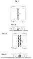
- Figure 1is a schematic plan view of an apparatus according to the invention in a simple embodiment.
- FIG. 2is a schematic side view of an apparatus according to the invention in the embodiment of Figure 1.
- Figure 3is a schematic plan view of an apparatus according to the invention in another embodiment.
- Figure 4is a schematic side view of an apparatus according to the invention in the embodiment of Figure 3.
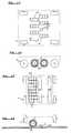
- Figure 5is a schematic plan view of an apparatus according to the invention in a variant of the embodiment of the figure 3, in which the brushes are staggered.
- Figure 6is a schematic side view of an apparatus according to the invention in the variant of FIG. 5.
- Figure 7is a schematic plan view of an apparatus according to the invention in a variant of the embodiment shown in Figures 1 and 2, in which the brushes are replaced by rollers.
- Figure 8is a schematic side view of an apparatus according to the invention in the variant of FIG. 7.
- FIG 9is a schematic plan view of an apparatus according to the invention in the variant shown in Figures 7 and 8, in which the rollers are staggered.
- Figure 10is a schematic side view of an apparatus according to the invention in the variant of FIG. 9.
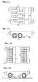
- Figure 11is a schematic plan view of an apparatus according to the invention in the variant of the embodiment shown in Figures 7 and 8, in which the rollers are arranged in rotating barrels.
- Figure 12is a schematic side view of an apparatus according to the invention in the variant of FIG. 11.
- Figure 13is a schematic plan view of an apparatus according to the invention in the variant shown in FIGS. 11 and 12, in which the rotating barrels carrying the rollers are staggered.
- Figure 14is a schematic side view of an apparatus according to the invention in the variant of FIG. 13.
- Figure 15is a schematic plan view of an apparatus according to the invention in another embodiment, in which the rollers which do not support the device are arranged in rotating barrels.
- Figure 16is a schematic side view of an apparatus according to the invention in the embodiment of Figure 15.
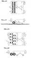
- Figure 17is a schematic plan view of an apparatus according to the invention in the embodiment shown in Figures 15 and 16, in which the rotating barrels carrying the rollers are staggered.
- Figure 18is a schematic side view of an apparatus according to the invention in the variant of FIG. 17.
- Figure 19is a schematic plan view of an apparatus according to the invention in the embodiment of Figures 15 and 16, in which the rotating barrels are arranged on either side carrier rollers.
- Figure 20is a schematic side view of an apparatus according to the invention in the variant of FIG. 19.
- Figure 21is a schematic plan view of an apparatus according to the invention in the embodiment of Figure 15, the rollers non-carriers arranged in rotating barrels being replaced by rotating brushes.
- Figure 22is a schematic side view of an apparatus according to the invention in the variant of FIG. 21.
- Figure 23is a schematic plan view of an apparatus according to the invention in the embodiment of Figure 17, the rotating barrels carrying rollers being replaced by rotating brushes.
- Figure 24is a schematic side view of an apparatus according to the invention in the variant of FIG. 23.
- Figure 25is a schematic plan view of an apparatus according to the invention in the embodiment of Figure 19, the rollers non-carriers arranged in rotating barrels being replaced by rotating brushes.
- Figure 26is a schematic side view of an apparatus according to the invention in the variant of FIG. 25.
- Figure 27is a plan view of an apparatus according to the invention in the embodiment of Figure 25, in which the rotary brushes are staggered and in which the transmission of motor movement is by belts.
- Figure 28is a longitudinal sectional view along A-A of apparatus according to the invention in the variant of FIG. 27.
- Figure 29is a cross-sectional view along B-B of a apparatus according to the invention in the variant of FIG. 27.
- Figure 30is a cross-sectional view along C-C of a apparatus according to the invention in the variant of FIG. 27.
- Figure 31is a diagram of an electronic control device and electric of an apparatus according to the invention.
- Figure 32shows a lawn area divided into several sectors with a mark inscribed by points in sectors chosen, all the points forming the mark.
- Figure 33shows a network of metallic cables or wires buried in the grass surface and allowing the positioning of the device in the field.
- Figure 34shows a sports field with four surfaces to mark and two transceivers allowing the positioning of the device in the field.
- the device according to the inventionis equipped with four wheels 1 and a row of brushes 2 whose filaments are directed vertically towards the lawn.
- the wheelsare used to transport the appliance to the grass surface to be treated, and to move it over this surface.
- the wheelsare moved by one or more motors, preferably electric, not shown here. They are equipped with a steering device.
- Each brushis equipped a device allowing it to be lowered to the lawn and lift above the lawn. When the device passes over the surface of grass to be treated, the brushes are lowered at the right time.
- each brushhas a width which corresponds to that of a determined area on the surface to be treated.
- This embodiment of the deviceis the first which is described above, and the simplest.
- the turf surface to be treatedis treated as a network of small sectors 13, of preferably quadrangular, as shown in Figure 32. If the width of the surface to be treated is greater than the length of the row of brushes, it is useful to treat the surface with several parallel tracks 14 whose width corresponds to the length of the appliance's brush row.
- the surface shown in Figure 32is thus divided into four tracks including the width corresponds to eight sectors, the latter number corresponding to the number of brushes provided the device.
- the figure 32shows that, on the fourth track, the third brush of the row lowers on the twelfth and thirteenth sectors from the left, and then gets up, marking the lawn of two sectors in question by orienting their strands of grass. A part of the letter A is thus marked on the lawn. The rest of the grass surface can of course remain as it was, without any treatment. It is however clearly preferable to run the device for the first time, all brushes lowered in one direction to orient all the strands of the turf on an entire track. Then we pass the device in the other direction, lowering the brushes only on the sectors representing the sign or image to be represented. Of the so the strands are oriented, basically, in two directions only, which gives a sharper image.
- the deviceis placed again on the starting line, at the start of the second track, which runs parallel to the first one and which is adjacent to it, and the process starts again, until the entire lawn area is treated.
- the brushes 2are always in a row, but they are rotatable and can turn independently of one another in one direction or in the other. Likewise, they can be braked or blocked, or still rotate freely, independently of each other.
- a brushis blocked or turns back, the bristles of the grass tilt in the direction of travel of the device. When it turns forward, at a speed that exceeds that of the device, the strands of the lawn tilt in one direction opposite.
- the devicecan thus process an entire track by one pass. At the end of a track, it turns around and immediately begins the next track, in the opposite direction.
- Figures 5 and 6show an embodiment in which the brushes are staggered, which facilitates installation transmissions and control elements, and allows processing the entire lawn area, without gaps.
- An automatic device, classic typeallows to operate at the right time brushes, despite the shift in their position.
- the row of brushesis replaced by a row of rollers 3 mounted so to rotate freely.
- the rollersare staggered.
- An automatic device, classic typeallows the rollers to be lowered at the right time, despite the shift in their position.
- the rollers of Figures 7 and 8have a central division which allows them to be pressed bearings, central bearings or bearings, while the rollers of Figures 9 and 8 are carried by bearings, bearings or bearings placed on each side.
- the rollersare mounted on a device which allows to lower and raise them independently of each other.
- the apparatusfunctions like that which is shown in Figures 1 and 2. In other words, the device must pass twice on the same track if the entire surface must be treated.
- the row of brushes in figures 3 and 4is replaced by a row of rotating barrels 15 on the periphery of which rollers 3 are mounted so as to rotate freely around axes parallel to that of the barrel.
- Barrels 15can rotate in both sense, or be held back, independently of each other, thanks to motors which are not shown.
- a barrelis blocked or turns back, the strands of the lawn tilt into the direction of travel of the device.
- the strands of the lawntilt in an opposite direction.
- the devicecan thus process an entire track in one pass. Arrived at the end of a track, he turns around and immediately starts the track next, in the opposite direction.
- the deviceis preferably provided a device for raising the barrels so as not to not damage them during the journey to the lawn surface and during the return journey.
- Figures 13 and 14show a variant of this latter form of execution, in which the rotary barrels 15 are mounted in staggered, with the advantages mentioned regarding Figures 5 and 6.
- a devicemakes it possible to adapt the operation the offset between the barrels.
- the deviceis provided with eight barrels 15 carrying rolls 3 and four rolls 3 placed in pairs.
- the axes of wheels 1are perpendicular to those of the rollers.
- the deviceis provided with means enabling the wheels to be raised so that the device rests on the two pairs of rollers.
- the deviceis brought to the grass surface to be treated by means of the wheels lowered.
- the wheelsare raised and the device moves, perpendicular to its direction of arrival, on the surface thanks to the two pairs of rollers, which are driven by one or more motors.
- the two rolls of each pairare separated by a small space which avoids friction. It is easy to turn the device by braking the rollers located on the same side, which is possible thanks to a differential whose transmission is equipped. A differential is not necessary if each roller is driven by a different motor.
- the device for raising and lowering the wheelsis not not shown here. This is a classic device, as it for example, for decades on some models of trucks or planes.
- each pair of rollers and the set of rotary barrels 15corresponds to the width of a track 14 of the turf surface.
- the strands of the entire runway turfare first oriented in the direction of movement of the device by the carrying rollers. Then the rotating barrels pass and give a different or identical orientation, depending on the direction and the speed of their rotation, as explained regarding Figures 11 and 12.
- a trackcan therefore be treated as a single passage. However, if you want to mark the next track on the way back, you must return the device to prevent carrying rollers, following the passage of the rotating barrels, erase the marks made by them.
- Figures 17 and 18show a variant of this latter form in which the rotating barrels are mounted in staggered, with the advantages mentioned regarding Figures 5 and 6 and 13 and 14.
- a devicemakes it possible to adapt the offset operation between the barrels.
- Figures 19 and 20show a variant of the embodiment Figures 15 and 16, in which the two pairs of rollers carriers are surrounded by two rows of rotating barrels roller carriers.
- the presence of a row of barrels of each side of the carrying rollersallows to mark the track next in reverse, without turning the unit over. It is however note that it is preferable in principle to treat each track in the same direction to get orientation too uniform as possible of the strands of the lawn.
- the device in the form for the execution of FIGS. 19 and 20carries rotating barrels staggered, with the advantages described above.
- FIGS 21 to 26show alternative embodiments shown in Figures 15 to 20, in which the barrels are replaced by rotating brushes. Like the barrels in previous embodiments, each rotary brush can turn in one direction or the other independently of the others.
- Figures 27 to 30show the preferred embodiment of the device. This is the embodiment shown schematically in Figures 25 and 26, with the difference that the brushes are staggered, with the advantages that a such provision includes.
- Each rotary brush 2can rotate freely around the axis 7 and is controlled by a belt 4 which drives the brush by a pulley 10 secured to the brush.
- Each belt 4is driven by a motor 11, preferably electric, independent of the others.
- the brushesare placed at a height such that they penetrate in the grass, but do not touch the ground.
- the main axes 7 brushesare fixed by their ends to the main frame 5.
- Each pair of carrying rollersis carried by an axis 6.
- the carrier rollersrotate freely around the axis.
- Both ends of each axisare pulleys 10 each of which is integral with the carrying roller 3.
- Each motortransmits its movement via a gear train 12.
- the axes roller carriers, as well as motor-gear assemblies,are fixed on a secondary chassis 8.
- This secondary chassis 8is itself fixed to a main frame 5 by means of a ball bearing 9 which allows the chassis to turn a small angle to steer the device. The fact that each roll is controlled by an independent motor makes a differential unnecessary.
- the motorsare electric and are powered by an accumulator. It goes without saying that other types of motors could be used, but they would be less practical. Likewise, it would possible to use a different means of transmission than belts and pulleys, for example chains or gears.
- the motors and transmissions that drive the rollersensure the device, thanks to the significant reduction given by the gears, and even with variations in load, a substantially constant speed, which is roughly that of a man in step.
- roller motorsare started manually, using switches or switches controlled by the driver.
- the lattercan manually direct the device steering, which allows the two chassis to be pivoted secondary to the main chassis.
- the computerdirects the device automatically.
- FIG. 31gives a diagram of the relationships between the various electrical and electronic components that control the device. he note that the torque required to rotate a brush, whether in the direction of travel of the device or in the direction on the contrary, is substantially constant. The flexibility of the filaments of the brush plays an important role here.
- the advantage of the shape preferred executionlies in the best weight distribution.
- the preferred embodimentavoids marking of train paths by wheels in the field.
- the advantagealso lies in the large mass and also in the large dimensions of the barrels.
- the number of organscan vary according to the needs, whether rollers, barrels, brushes, motors, pulleys or wheels.
- the method of marking grass landis automatic.
- a device enslavement to a computeris essential.
- the image or images, or the or the signs, for example a name or a word constituting a mark, which must be reproduced on the grass,are introduced in the computer.
- the image (s) and / or the sign (s)are cut out at several points which correspond to a division into several sectors 13 of the turf surface.
- Driverplaces first the apparatus on the starting line 15. It directs it first along of the first track, manually.
- the deviceis equipped with a device that places on the edge of the runway, to the left of the apparatus in the embodiment shown in Figure 33, at regular intervals, for example at the edge of each sector 13, small ferromagnetic metal balls.
- the deviceis in additionally equipped with magnetic sensors connected to the computer, and a magnetic device which allows the beads to be recovered passage.
- the ballsare deposited when the device passes over the first track.
- the computercauses the balls to drop and operates the brushes and / or rollers when where the device is in a determined position.
- the preferred methodconsists in providing the device with a distance counter, which is operated by one or more of the rollers which support the device, or by a wheel attached to the device and which rolls freely on the lawn.
- Such countersare instruments common, for example on automobiles.
- the metertransmits its indications to the computer, which transmits its instructions to engines according to the program introduced by the driver.
- the sensorstransmit to the computer the data they collect as to the position of the device compared to that of the balls. It is no longer the counter which is decisive.
- the position of the ballsdoes not determine not only the direction given to the device, but also the when the brush or roller must come into action to give on the lawn the desired direction in a given sector, as well as the position of the new series of balls to be deposited along the second track: while the aircraft retrieves the balls placed at the edge of the first track, he deposits it at the edge of the second track. Of course, it can be the same balls that are transferred by the device from the edge of the first to the edge of the second track.
- the driverplaces the aircraft again on the starting line, at the start of the next track, and the process starts again. Arrived at the last track, the computer orders the device that deposits the balls of no longer work, only the one who ensures the collection of logs at the edge of the penultimate runway.
- the computercauses a line to be marked in the grass, at the edge of the track.
- the driverthus guides the aircraft to the next runway along the line thus drawn.
- the linewill be plotted so that the passage of the device for the treatment of the next track will erase it. In other words, it will take the device goes over.
- the device erase this first linehe draws a second one, at the edge of the second track. This second line will be deleted by passing of the aircraft on the third track. The process starts again until the entire surface has been treated.
- Another form of method executionis to bury in the ground, a few centimeters from the surface, a grid metallic which corresponds to the edges of the tracks and the lines of departure and arrival, as shown in figure 33.
- the deviceis equipped with sensors which transmit the position of the device.
- a measuring devicesignals to the computer and driver any deviation between the actual position of the device and the predicted position and stored in the computer.
- the pilotingcan be automatic or manual.
- transceiversin the field and on the aircraft.
- Such devicesto measure distance and / or angle, which allows the computer to calculate the position of the device by compared to the transceivers placed on the ground.
- Figure 34shows schematically that such transceivers could be placed in A and B. Microwaves, ultrasound or infrared can be used in such a system.
- pilotingcan be automatic or manual.
Landscapes
- Engineering & Computer Science (AREA)
- Architecture (AREA)
- Civil Engineering (AREA)
- Structural Engineering (AREA)
- General Physics & Mathematics (AREA)
- Accounting & Taxation (AREA)
- Marketing (AREA)
- Physics & Mathematics (AREA)
- Business, Economics & Management (AREA)
- Theoretical Computer Science (AREA)
- Soil Working Implements (AREA)
- Application Of Or Painting With Fluid Materials (AREA)
- Transplanting Machines (AREA)
- Pretreatment Of Seeds And Plants (AREA)
- Finish Polishing, Edge Sharpening, And Grinding By Specific Grinding Devices (AREA)
- Harvester Elements (AREA)
Abstract
Description
Translated fromFrenchLa présente invention a trait essentiellement aux techniques decommunication de masse, et plus particulièrement aux techniquesd'affichage publicitaire. L'invention a particulièrement pour objetl'exploitation d'espaces non encore utilisés à ce jour pour lapublicité, à savoir les terrains de sport.The present invention relates essentially to the techniques ofmass communication, and more specifically to techniquesadvertising display. The subject of the invention is particularlythe exploitation of spaces not yet used to date for theadvertising, namely sports fields.
Dans les événement qui se déroulent sur des terrains de gazon,c'est-à-dire essentiellement des manifestations sportives, denombreux panneaux publicitaires bordent habituellement le terrain.Le gazon lui-même, qui est pourtant l'endroit que le public voit leplus fréquemment, et qui est la plus grande surface que lesspectateurs ont sous les yeux, ne porte cependant aucune publicité.Les seules marques inscrites sur le terrain sont celles qui ont unesignification sportive ou décorative. Les premières sont en généralblanches ou colorées. Quant aux secondes, elles sont fréquemmentimprimées simplement en variant le sens des passages de latondeuse, de façon à former, par exemple, des damiers ou des bandesdans lesquels les brins d'herbe sont orientés différemment sur dessurfaces adjacentes. L'idée de faire subir à une partie d'unesurface de gazon un traitement différent de celui que subit uneautre partie de la surface, de façon à former des inscriptions oudessins publicitaires, a été exposée dans le brevet FR 2 567 359.Le procédé décrit dans ce document utilise toutefois un chablonpour recouvrir une partie de l'herbe et pour empêcher letraitement, par exemple l'application d'un engrais ou une tontesuivie d'un brossage ou d'un passage au rouleau, d'atteindre lesparties masquées par le chablon.In events that take place on turf fields,that is to say essentially sporting events,many billboards usually line the field.The grass itself, which is the place the public sees themore frequently, and that is the larger area than thespectators have before their eyes, however does not carry any advertising.The only brands registered in the field are those with asporty or decorative significance. The former are generallywhite or colored. As for the seconds, they are frequentlyprinted simply by varying the direction of the passages in themower, so as to form, for example, checkerboards or bandsin which the blades of grass are oriented differently onadjacent surfaces. The idea of subjecting part of aturf surface treated differently from aother part of the surface, so as to form inscriptions oradvertising designs, has been exposed in
La présente invention vise à permettre l'inscription de messages,notamment publicitaires, sur la surface de gazon elle-même, sansque ces messages créent de confusions avec les marquages àsignification sportive et sans utilisation d'un chablon.The present invention aims to allow the recording of messages,including advertising, on the grass surface itself, withoutthat these messages create confusion with the markings tosporty significance and without the use of a stencil.
La présente invention vise à fournir un procédé permettant demarquer le gazon avec des signes, comme par exemple des lettresformant des mots ou des noms, ou des chiffres, ou des images, et àfournir un appareil apte à effectuer un tel marquage.The present invention aims to provide a method formark the grass with signs, such as lettersforming words or names, or numbers, or images, and atprovide a device capable of carrying out such marking.
Dans le procédé de marquage selon l'invention, on oriente unepartie des brins d'une surface de gazon dans une direction, et onoriente ou qu'on laisse orientés dans au moins une autre directionau moins une autre partie des brins de ladite surface de gazon, defaçon qu'au moins une des parties constitue une image ou unsigne.Il s'agit là du même procédé déjà connu et employé au moyende tondeuses, le procédé selon l'invention n'étant cependant pasnécessairement lié à la tonte. Le procédé selon l'invention sedistingue en outre de l'état connu de la technique par diversescaractéristiques. Dans une première forme d'exécution, le procédéde marquage pour terrains en gazon, notamment terrains de sport,est caractérisé en ce qu'on introduit dans un ordinateur un modèledu signe ou de l'image à marquer sur le gazon, en ce qu'on diviseledit modèle en plusieurs points, en ce qu'on divise la surface degazon en plusieurs secteurs, en ce qu'on introduit en outre dansl'ordinateur la position instantanée de moyens (2, 3) d'orienterles brins du gazon, et en ce qu'on commande l'action desditsmoyens, en fonction de leur position sur des secteurs déterminésqui correspondent à des points déterminés du modèle, du signe ou del'image à marquer sur la surface de gazon.In the marking method according to the invention, apart of the strands of a grass surface in one direction, and weorient or let it orient in at least one other directionat least one other part of the strands of said turf surface,so that at least one of the parts constitutes an image or asign. This is the same process already known and used by meansmowers, the method according to the invention however notnecessarily related to mowing. The method according to the invention isfurther distinguishes from the known state of the art by variouscharacteristics. In a first embodiment, the methodmarking for turf fields, in particular sports fields,is characterized in that a model is introduced into a computerof the sign or image to mark on the lawn, in that we dividesaid model in several points, in that we divide the area oflawn in several sectors, in that we also introducethe computer the instant position of means (2, 3) to orientthe strands of the lawn, and in that we control the action of saidresources, depending on their position in specific sectorswhich correspond to determined points of the model, sign orthe image to be marked on the grass surface.
Dans une deuxième forme d'exécution, le procédé selon la premièreforme d'exécution est caractérisé en ce qu'on oriente les brinsd'au moins une partie de la surface de gazon au moyen d'une ou deplusieurs brosses.In a second embodiment, the method according to the firstembodiment is characterized in that the strands are orientedat least part of the lawn surface using one or moreseveral brushes.
Dans une troisième forme d'exécution, le procédé selon la deuxièmeforme d'exécution est caractérisé en ce qu'on utilise des brossesrotatives.In a third embodiment, the method according to the secondembodiment is characterized in that brushes are usedrotary.
Dans une quatrième forme d'exécution, le procédé selon la premièreforme d'exécution est caractérisé en ce qu'on oriente les brinsd'au moins une partie de la surface de gazon au moyen d'un ou deplusieurs rouleaux.In a fourth embodiment, the method according to the firstembodiment is characterized in that the strands are orientedat least part of the lawn surface using one or moremultiple rolls.
Dans une cinquième forme d'exécution, le procédé selon la premièreforme d'exécution est caractérisé en ce qu'on oriente les brins dela surface de gazon au moyen d'une ou de plusieurs brosses et aumoyen d'un ou de plusieurs rouleaux.In a fifth embodiment, the method according to the firstembodiment is characterized in that the strands ofthe grass surface using one or more brushes and atby means of one or more rollers.
Dans une sixième forme d'exécution, le procédé selon l'une des cinqpremières formes d'exécution décrites plus haut est caractérisé ence que la commande de l'action des moyens d'orientation des brinsdu gazon, et notamment de l'abaissement, de l'élévation et/ou de larotation des brosses et/ou rouleaux est asservie à l'ordinateurdans lequel sont introduits le ou les modèles de signes ou images àmarquer sur la surface de gazon divisés en points, la position desbrosses et/ou rouleaux par rapport à celle des divers secteurs dela surface de gazon et des instructions commandant ladite action enfonction de ladite position.In a sixth embodiment, the method according to one of the fivefirst embodiments described above is characterized bywhat the control of the action of the strand orientation meansturf, and in particular the lowering, raising and / orrotation of brushes and / or rollers is controlled by the computerin which are introduced the model or models of signs or images tomark on the grass surface divided into points, the position ofbrushes and / or rollers compared to that of the various sectors ofthe turf surface and instructions commanding said action bydepending on said position.
Dans une autre variante de la sixième forme d'exécution décriteplus haut, le procédé est caractérisé en ce qu'on utilise unappareil sur lequel sont fixés les brosses ou rouleaux et en ceque la position dudit appareil sur la surface de gazon estconstatée par des senseurs qui détectent la présence de corpsmagnétisables qui sont déposés ou enterrés à des endroitsdéterminés sur ou sous ladite surface.In another variant of the sixth embodiment describedabove, the process is characterized in that adevice on which the brushes or rollers are fixed andthat the position of said device on the lawn surface isdetected by sensors that detect the presence of bodiesmagnetizable which are deposited or buried in placesdetermined on or under said surface.
Dans une autre variante encore de la sixième forme d'exécutiondécrite plus haut, le procédé est caractérisé en ce qu'on utiliseun appareil sur lequel sont fixés les brosses ou rouleaux et en ceque la position dudit appareil sur la surface de gazon estconstatée par un dispositif émetteur et récepteur d'ondesélectromagnétiques ou soniques.In yet another variant of the sixth embodimentdescribed above, the method is characterized in that one usesa device on which the brushes or rollers are fixed and in thisthat the position of said device on the lawn surface isobserved by a wave transmitter and receiver deviceelectromagnetic or sonic.
Dans une forme d'exécution particulière de cette dernière variante,le procédé est caractérisé en ce que le dispositif reçoit dessignaux de satellites géostationnaires.In a particular embodiment of this latter variant,the method is characterized in that the device receivessignals from geostationary satellites.
L'appareil pour marquer les terrains en gazon, dans une premièreforme d'exécution, comprend des rouespermettant son déplacement, des brosses et/ou des rouleaux, et desmoyens permettant d'abaisser sélectivement jusqu'au gazon et de relever de façonqu'ils ne touchent plus le gazon certains desdits brosseset/ou rouleaux.The device for marking turf fields, in a firstembodiment, includes wheelsallowing its displacement, brushes and / or rollers, andmeans for selectively lowering to the grass and raising sothat they no longer touch the grass some of said brushesand / or rollers.
Dans une deuxième forme d'exécution, l'appareilcomprend des brosses rotatives, comme les rouleaux, et desmoyens de faire tourner les brosses dans les deux sens.In a second embodiment, the deviceincludes rotating brushes, such as rollers, andways to rotate the brushes back and forth.
Dans une troisième forme d'exécution, qui est une variante de ladeuxième, l'appareil comprend des moyens permettant d'abaisser aumoins certaines des brosses rotatives jusqu'au gazon et de lesrelever de façon qu'elles ne touchent plus le gazon.In a third embodiment, which is a variant of thesecond, the apparatus includes means for lowering theminus some of the rotary brushes down to the lawn andraise so that they no longer touch the lawn.
Dans une quatrième forme d'exécution, l'appareil selon l'une desformes d'exécution ci-dessus est caractérisé en ce que les brosseset/ou les rouleaux sont réunis par groupes.In a fourth embodiment, the apparatus according to one ofabove embodiments is characterized in that the brushesand / or the rollers are grouped together.
Dans une cinquième forme d'exécution, l'appareil selon l'une desformes d'exécution décrites ci-dessus est caractérisé en ce qu'aumoins une partie des rouleaux sont réunis sur un ou plusieursbarillets rotatifs sur lesquels ils sont montés de façon à tournerlibrement.In a fifth embodiment, the apparatus according to one ofembodiments described above is characterized in that atat least part of the rollers are joined on one or morerotary barrels on which they are mounted so as to rotatefreely.
Dans une sixième forme d'exécution, l'appareil selon l'une desformes d'exécution décrites ci-dessus est caractérisé en ce que lesbrosses et/ou les rouleaux et/ou les groupes de rouleaux et/ou debrosses sont montés en quinconce.In a sixth embodiment, the apparatus according to one ofembodiments described above is characterized in that thebrushes and / or rollers and / or groups of rollers and / orbrushes are mounted in staggered rows.
Dans une septième forme d'exécution, l'appareil selon l'une desformes d'exécution décrites ci-dessus est caractérisé en ce qu'ilcomprend des moyens permettant de relever les roues, et desrouleaux permettant de soutenir et de déplacer l'appareil lorsqueles roues sont relevées.In a seventh embodiment, the device according to one ofembodiments described above is characterized in that itincludes means for lifting the wheels, androllers to support and move the device whenthe wheels are raised.
Dans une huitième forme d'exécution, l'appareil selon la septièmeforme d'exécution décrite ci-dessus est caractérisé en ce qu'ilcomprend au moins un moteur actionnant les rouleaux qui soutiennentl'appareil et un dispositif de direction permettant de dirigerl'appareil lorsque les roues sont relevées.In an eighth embodiment, the apparatus according to the seventhembodiment described above is characterized in that itcomprises at least one motor actuating the rollers which supportthe apparatus and a steering device for directingwhen the wheels are raised.
Dans une neuvième forme d'exécution, l'appareil selon l'une desdeux dernières formes d'exécution décrites ci-dessus estcaractérisé en ce que chaque rouleau ou groupe de rouleaux etchaque brosse ou groupe de brosses est commandé par un moteurdifférent.In a ninth embodiment, the apparatus according to one oflast two embodiments described above ischaracterized in that each roller or group of rollers andeach brush or group of brushes is controlled by a motordifferent.
Dans une dixième forme d'exécution, l'appareil selon l'une desformes d'exécution décrites ci-dessus comprend un compteur actionnépar les rouleaux porteurs de l'appareil ou par une roue qui roulesur la surface de gazon et qui détermine la position dudit appareilsur la surface de gazon.In a tenth embodiment, the apparatus according to one ofembodiments described above includes an activated counterby the carrying rollers of the device or by a rolling wheelon the grass surface and which determines the position of said deviceon the grass surface.
Dans une onzième forme d'exécution, l'appareil selon l'une desquatre dernières formes d'exécution décrites ci-dessus estcaractérisé en ce que les axes de rotation des roues sontperpendiculaires aux axes de rotation des rouleaux et/ou desbrosses.In an eleventh embodiment, the apparatus according to one oflast four embodiments described above ischaracterized in that the axes of rotation of the wheels areperpendicular to the axes of rotation of the rollers and / orbrushes.
Selon une variante de toutes les formes d'exécution décritesjusqu'ici, l'appareil est caractérisé en ce qu'il comprend unordinateur dans lequel sont introduits un ou des modèles de l'imageou des images ou du ou des signes à marquer sur le gazon et laposition de l'appareil sur la surface de gazon et des moyenspermettant à l'ordinateur d'actionner les brosses et/ou lesrouleaux en fonction de ces données de façon à orienter au moinsune partie des brins de la surface de gazon dans une directiondifférente de celle des autres brins, de façon qu'au moins une desparties de la surface de gazon constitue une image ou un signecorrespondant à celui qui est introduit dans l'ordinateur.According to a variant of all the described embodimentsso far, the device is characterized in that it comprises acomputer in which one or more models of the image are introducedor pictures or sign (s) to mark on the grass and theposition of the device on the turf surface and meansallowing the computer to operate the brushes and / orrolls based on this data so as to orient at leastpart of the strands of the turf surface in one directiondifferent from that of the other strands, so that at least one of theparts of the turf surface constitutes an image or signcorresponding to the one that is entered into the computer.
Les dessins montrent, à titre d'exemples, quelques formesd'exécution de l'invention.The drawings show, as examples, some shapesof the invention.
La figure 1 est une vue schématique en plan d'un appareil selonl'invention dans une forme d'exécution simple.Figure 1 is a schematic plan view of an apparatus according tothe invention in a simple embodiment.
La figure 2 est une vue schématique latérale d'un appareil selonl'invention dans la forme d'exécution de la figure 1.Figure 2 is a schematic side view of an apparatus according tothe invention in the embodiment of Figure 1.
La figure 3 est une vue schématique en plan d'un appareil selonl'invention dans une autre forme d'exécution.Figure 3 is a schematic plan view of an apparatus according tothe invention in another embodiment.
La figure 4 est une vue schématique latérale d'un appareil selonl'invention dans la forme d'exécution de la figure 3.Figure 4 is a schematic side view of an apparatus according tothe invention in the embodiment of Figure 3.
La figure 5 est une vue schématique en plan d'un appareil selonl'invention dans une variante de la forme d'exécution de la figure3, dans laquelle les brosses sont disposées en quinconce.Figure 5 is a schematic plan view of an apparatus according tothe invention in a variant of the embodiment of the figure3, in which the brushes are staggered.
La figure 6 est une vue schématique latérale d'un appareil selonl'invention dans la variante de la figure 5.Figure 6 is a schematic side view of an apparatus according tothe invention in the variant of FIG. 5.
La figure 7 est une vue schématique en plan d'un appareil selonl'invention dans une variante de la forme d'exécution représentéeaux figures 1 et 2, dans laquelle les brosses sont remplacées pardes rouleaux.Figure 7 is a schematic plan view of an apparatus according tothe invention in a variant of the embodiment shownin Figures 1 and 2, in which the brushes are replaced byrollers.
La figure 8 est une vue schématique latérale d'un appareil selonl'invention dans la variante de la figure 7.Figure 8 is a schematic side view of an apparatus according tothe invention in the variant of FIG. 7.
La figure 9 est une vue schématique en plan d'un appareil selonl'invention dans la variante représentée aux figures 7 et 8, danslaquelle les rouleaux sont disposés en quinconce.Figure 9 is a schematic plan view of an apparatus according tothe invention in the variant shown in Figures 7 and 8, inwhich the rollers are staggered.
La figure 10 est une vue schématique latérale d'un appareil selonl'invention dans la variante de la figure 9.Figure 10 is a schematic side view of an apparatus according tothe invention in the variant of FIG. 9.
La figure 11 est une vue schématique en plan d'un appareil selonl'invention dans la variante de la forme d'exécution représentéeaux figures 7 et 8, dans laquelle les rouleaux sont disposés enbarillets rotatifs.Figure 11 is a schematic plan view of an apparatus according tothe invention in the variant of the embodiment shownin Figures 7 and 8, in which the rollers are arranged inrotating barrels.
La figure 12 est une vue schématique latérale d'un appareil selonl'invention dans la variante de la figure 11.Figure 12 is a schematic side view of an apparatus according tothe invention in the variant of FIG. 11.
La figure 13 est une vue schématique en plan d'un appareil selonl'invention dans la variante représentée aux figures 11 et 12,dans laquelle les barillets rotatifs portant les rouleaux sontdisposés en quinconce.Figure 13 is a schematic plan view of an apparatus according tothe invention in the variant shown in FIGS. 11 and 12,in which the rotating barrels carrying the rollers arestaggered.
La figure 14 est une vue schématique latérale d'un appareil selonl'invention dans la variante de la figure 13.Figure 14 is a schematic side view of an apparatus according tothe invention in the variant of FIG. 13.
La figure 15 est une vue schématique en plan d'un appareil selonl'invention dans une autre forme d'exécution, dans laquelle lesrouleaux qui ne soutiennent pas l'appareil sont disposés enbarillets rotatifs.Figure 15 is a schematic plan view of an apparatus according tothe invention in another embodiment, in which therollers which do not support the device are arranged inrotating barrels.
La figure 16 est une vue schématique latérale d'un appareil selonl'invention dans la forme d'exécution de la figure 15.Figure 16 is a schematic side view of an apparatus according tothe invention in the embodiment of Figure 15.
La figure 17 est une vue schématique en plan d'un appareil selonl'invention dans la forme d'exécution représentée aux figures 15 et16, dans laquelle les barillets rotatifs portant les rouleauxsont disposés en quinconce.Figure 17 is a schematic plan view of an apparatus according tothe invention in the embodiment shown in Figures 15 and16, in which the rotating barrels carrying the rollersare staggered.
La figure 18 est une vue schématique latérale d'un appareil selonl'invention dans la variante de la figure 17.Figure 18 is a schematic side view of an apparatus according tothe invention in the variant of FIG. 17.
La figure 19 est une vue schématique en plan d'un appareil selonl'invention dans la forme d'exécution des figures 15 et 16, danslaquelle les barillets rotatifs sont disposés de part et d'autredes rouleaux porteurs.Figure 19 is a schematic plan view of an apparatus according tothe invention in the embodiment of Figures 15 and 16, inwhich the rotating barrels are arranged on either sidecarrier rollers.
La figure 20 est une vue schématique latérale d'un appareil selonl'invention dans la variante de la figure 19.Figure 20 is a schematic side view of an apparatus according tothe invention in the variant of FIG. 19.
La figure 21 est une vue schématique en plan d'un appareil selonl'invention dans la forme d'exécution de la figure 15, les rouleauxnon porteurs disposés en barillets rotatifs étant remplacés par desbrosses rotatives.Figure 21 is a schematic plan view of an apparatus according tothe invention in the embodiment of Figure 15, the rollersnon-carriers arranged in rotating barrels being replaced byrotating brushes.
La figure 22 est une vue schématique latérale d'un appareil selonl'invention dans la variante de la figure 21.Figure 22 is a schematic side view of an apparatus according tothe invention in the variant of FIG. 21.
La figure 23 est une vue schématique en plan d'un appareil selonl'invention dans la forme d'exécution de la figure 17, lesbarillets rotatifs porteurs de rouleaux étant remplacés par desbrosses rotatives.Figure 23 is a schematic plan view of an apparatus according tothe invention in the embodiment of Figure 17, therotating barrels carrying rollers being replaced byrotating brushes.
La figure 24 est une vue schématique latérale d'un appareil selonl'invention dans la variante de la figure 23.Figure 24 is a schematic side view of an apparatus according tothe invention in the variant of FIG. 23.
La figure 25 est une vue schématique en plan d'un appareil selonl'invention dans la forme d'exécution de la figure 19, les rouleauxnon porteurs disposés en barillets rotatifs étant remplacés par desbrosses rotatives.Figure 25 is a schematic plan view of an apparatus according tothe invention in the embodiment of Figure 19, the rollersnon-carriers arranged in rotating barrels being replaced byrotating brushes.
La figure 26 est une vue schématique latérale d'un appareil selonl'invention dans la variante de la figure 25.Figure 26 is a schematic side view of an apparatus according tothe invention in the variant of FIG. 25.
La figure 27 est une vue en plan d'un appareil selon l'inventiondans la forme d'exécution de la figure 25, dans laquelle lesbrosses rotatives sont disposées en quinconce et dans laquelle latransmission du mouvement du moteur se fait par courroies.Figure 27 is a plan view of an apparatus according to the inventionin the embodiment of Figure 25, in which therotary brushes are staggered and in which thetransmission of motor movement is by belts.
La figure 28 est une vue en coupe longitudinale selon A-A d'unappareil selon l'invention dans la variante de la figure 27.Figure 28 is a longitudinal sectional view along A-A ofapparatus according to the invention in the variant of FIG. 27.
La figure 29 est une vue en coupe transversale selon B-B d'unappareil selon l'invention dans la variante de la figure 27.Figure 29 is a cross-sectional view along B-B of aapparatus according to the invention in the variant of FIG. 27.
La figure 30 est une vue en coupe transversale selon C-C d'unappareil selon l'invention dans la variante de la figure 27.Figure 30 is a cross-sectional view along C-C of aapparatus according to the invention in the variant of FIG. 27.
La figure 31 est un schéma d'un dispositif de commande électroniqueet électrique d'un appareil selon l'invention.Figure 31 is a diagram of an electronic control deviceand electric of an apparatus according to the invention.
La figure 32 représente une surface de gazon divisée en plusieurssecteurs avec une marque inscrite par des points dans des secteurschoisis, l'ensemble des points formant la marque.Figure 32 shows a lawn area divided into severalsectors with a mark inscribed by points in sectorschosen, all the points forming the mark.
La figure 33 représente un réseau de câbles ou fils métalliquesenterré dans la surface de gazon et permettant le positionnement del'appareil sur le terrain.Figure 33 shows a network of metallic cables or wiresburied in the grass surface and allowing the positioning ofthe device in the field.
La figure 34 représente un terrain de sport avec quatre surfaces àmarquer et deux transceivers permettant le positionnement del'appareil sur le terrain.Figure 34 shows a sports field with four surfaces tomark and two transceivers allowing the positioning ofthe device in the field.
Dans la forme d'exécution représentée schématiquement dans lesfigures 1 et 2, l'appareil selon l'invention est équipé de quatreroues 1 et d'une rangée de brosses 2 dont les filaments sontdirigés verticalement vers le gazon. Les roues servent àtransporter l'appareil jusqu'à la surface de gazon à traiter, et àle déplacer sur cette surface. Les roues sont mues par un ou desmoteurs, de préférence électriques, non représentés ici. Elles sont équipées d'un dispositif de direction. Chaque brosse est équipéed'un dispositif permettant de l'abaisser jusqu'au gazon et de larelever au-dessus du gazon. Lorsque l'appareil passe sur la surfacede gazon à traiter, les brosses s'abaissent au moment voulu. Depréférence, chaque brosse a une largeur qui correspond à celle d'unsecteur déterminé sur la surface à traiter.In the embodiment shown schematically in theFigures 1 and 2, the device according to the invention is equipped with four
Cette forme d'exécution de l'appareil est la première qui estdécrite plus haut, et la plus simple.This embodiment of the device is the first which isdescribed above, and the simplest.
Dans une forme d'exécution préférée du procédé, la surface de gazonà traiter est traitée comme un réseau de petits secteurs 13, depréférence quadrangulaires, comme le montre la figure 32. Si lalargeur de la surface à traiter est plus grande que la longueur dela rangée de brosses, il est utile de traiter la surface enplusieurs pistes 14 parallèles dont la largeur correspond à lalongueur de la rangée de brosses de l'appareil. La surfacereprésentée à la figure 32 est ainsi divisée en quatre pistes dontla largeur correspond à huit secteurs, ce dernier nombrecorrespondant lui-même au nombre de brosses dont est pourvul'appareil. L'appareil roule le long de la première piste.Lorsqu'une brosse passe au-dessus d'un secteur à traiter, elle estabaissée sur le gazon et elle oriente les brins du gazon aupassage, jusqu'au moment ou elle est relevée au-dessus du gazon. Lafigure 32 montre que, sur la quatrième piste, la troisième brossede la rangée s'abaisse sur les douzième et treizième secteursdepuis la gauche, et se relève ensuite, marquant ainsi le gazon desdeux secteurs en question en orientant leurs brins de gazon. Unepartie de la lettre A est ainsi marquée sur le gazon. Le reste dela surface de gazon peut bien entendu rester telle qu'elle était,sans aucun traitement. Il est cependant nettement préférable defaire passer l'appareil une première fois, toutes brossesabaissées, dans un sens, pour orienter l'ensemble des brins dugazon sur une piste entière. Ensuite, on fait passer l'appareildans l'autre sens, en abaissant les brosses seulement sur lessecteurs représentant le signe ou l'image à représenter. De lasorte, les brins sont orientés, en gros, dans deux directions seulement, ce qui donne une image plus nette. Une fois que lapremière piste est traitée, l'appareil est placé à nouveau sur laligne de départ, au début de la deuxième piste, qui est parallèle àla première et qui lui est adjacente, et le processus recommence,jusqu'à ce que la totalité de la surface de gazon soit traitée.In a preferred embodiment of the method, the turf surfaceto be treated is treated as a network of
Dans la forme d'exécution des figures 3 et 4, les brosses 2 sonttoujours sur une rangée, mais elles sont rotatives et peuventtourner indépendamment l'une de l'autre dans un sens ou dansl'autre. De même, elles peuvent être freinées ou bloquées, ouencore tourner librement, indépendamment l'une de l'autre.Lorsqu'une brosse est bloquée ou tourne en arrière, les brins dugazon s'inclinent dans la direction de la course de l'appareil.Lorsqu'elle tourne en avant, à une vitesse qui dépasse celle del'appareil, les brins du gazon s'inclinent dans une directionopposée. L'appareil peut ainsi traiter la totalité d'une piste enun seul passage. Arrivé au bout d'une piste, il fait demi-tour etcommence immédiatement la piste suivante, dans le sens opposé.In the embodiment of Figures 3 and 4, the
Pendant le trajet nécessaire pour amener l'appareil jusqu'à lasurface à traiter, il suffit de laisser les brosses tourner en rouelibre si l'appareil n'est pas muni d'un dispositif permettant deles relever. Il peut cependant être utile, dans certains cas,d'équiper l'appareil d'un tel dispositif.During the journey necessary to bring the device to thesurface to be treated, just let the brushes spinfree if the device is not equipped with a device allowingraise them. It may, however, be useful in some casesto equip the device with such a device.
Les figures 5 et 6 montrent une forme d'exécution dans laquelle lesbrosses sont disposées en quinconce, ce qui facilite l'installationdes transmissions et organes de commande, et permet de traitertoute la surface de gazon, sans lacunes. Un dispositif automatique,de type classique, permet de faire fonctionner au bon moment lesbrosses, malgré le décalage de leur position.Figures 5 and 6 show an embodiment in which thebrushes are staggered, which facilitates installationtransmissions and control elements, and allows processingthe entire lawn area, without gaps. An automatic device,classic type, allows to operate at the right timebrushes, despite the shift in their position.
Dans la forme d'exécution montrée aux figures 7 et 8, la rangée debrosses est remplacée par une rangée de rouleaux 3 montés de façonà tourner librement. Dans la forme d'exécution des figures 9 et 10,les rouleaux sont disposés en quinconce. Un dispositif automatique,de type classique, permet d'abaisser au bon moment les rouleaux,malgré le décalage de leur position. Les rouleaux des figures 7 et 8 présentent une division centrale qui permet de les appuyer surdes paliers, coussinets ou roulements centraux, alors que lesrouleaux des figures 9 et 8 sont portés par des paliers, coussinetsou roulements placés de chaque côté. Dans les deux formesd'exécution, les rouleaux sont montés sur un dispositif qui permetde les abaisser et de les élever indépendamment les uns des autres.Dans ces deux formes d'exécution, l'appareil fonctionne comme celuiqui est représenté aux figures 1 et 2. Autrement dit, l'appareildoit passer deux fois sur la même piste si l'ensemble de la surfacedoit être traité.In the embodiment shown in Figures 7 and 8, the row ofbrushes is replaced by a row of
Dans la forme d'exécution montrée aux figures 11 et 12, la rangéede brosses des figures 3 et 4 est remplacée par une rangée debarillets 15 rotatifs sur la périphérie desquels des rouleaux 3sont montés de façon à tourner librement autour d'axes parallèles àcelui du barillet. Les barillets 15 peuvent tourner dans les deuxsens, ou être freinés, indépendamment les uns des autres, grâce àdes moteurs qui ne sont pas représentés. Lorsqu'un barillet estbloqué ou tourne en arrière, les brins du gazon s'inclinent dans ladirection de la course de l'appareil. Lorsqu'il tourne en avant, àune vitesse qui dépasse celle de l'appareil, les brins du gazons'inclinent dans une direction opposée. L'appareil peut ainsitraiter la totalité d'une piste en un seul passage. Arrivé au boutd'une piste, il fait demi-tour et commence immédiatement la pistesuivante, dans le sens opposé. L'appareil est de préférence munid'un dispositif permettant de relever les barillets de façon à nepas les abímer pendant le trajet jusqu'à la surface de gazon etpendant le trajet de retour.In the embodiment shown in Figures 11 and 12, the rowof brushes in figures 3 and 4 is replaced by a row of
Les figures 13 et 14 montrent une variante de cette dernière formed'exécution, dans laquelle les barillets rotatifs 15 sont montés enquinconce, avec les avantages mentionnés concernant les figures 5et 6. Ici aussi, un dispositif permet d'adapter le fonctionnementau décalage entre les barillets.Figures 13 and 14 show a variant of this latter formof execution, in which the rotary barrels 15 are mounted instaggered, with the advantages mentioned regarding Figures 5and 6. Here too, a device makes it possible to adapt the operationthe offset between the barrels.
Dans la forme d'exécution représentée schématiquement aux figures15 et 16, l'appareil est pourvu de huit barillets 15 porteurs derouleaux 3 et de quatre rouleaux 3 placés par paires. Les axes des roues 1 sont perpendiculaires à ceux des rouleaux. L'appareil estpourvu de moyens permettant de relever les roues de façon quel'appareil repose sur les deux paires de rouleaux. L'appareil estamené sur la surface de gazon à traiter au moyen des rouesabaissées. Une fois arrivé, les roues sont relevées et l'appareilse meut, perpendiculairement à sa direction d'arrivée, sur lasurface grâce aux deux paires de rouleaux, qui sont entraínés parun ou plusieurs moteurs. Les deux rouleaux de chaque paire sontséparés par un petit espace qui évite les frottements. Il estfacile faire tourner l'appareil en freinant les rouleaux situésd'un même côté, ce qui est possible grâce à un différentiel dont latransmission est équipée. Un différentiel n'est pas nécessaire sichaque rouleau est entraíné par un moteur différent.In the embodiment shown schematically in the figures15 and 16, the device is provided with eight
Le dispositif qui permet de relever et d'abaisser les roues n'estpas représenté ici. Il s'agit d'un dispositif classique, comme ilen existe par exemple depuis des decennies sur certains modèles decamions ou d'avions.The device for raising and lowering the wheels is notnot shown here. This is a classic device, as itfor example, for decades on some models oftrucks or planes.
La longueur de chaque paire de rouleaux et de l'ensemble desbarillets rotatifs 15 correspond à la largeur d'une piste 14 de lasurface de gazon. Les brins de l'ensemble du gazon de la piste sontd'abord orientés dans la direction de déplacement de l'appareil parles rouleaux porteurs. Puis les barillets rotatifs passent etdonnent une orientation différente ou identique, selon le sens etla vitesse de leur rotation, comme cela a été expliqué concernantles figures 11 et 12. Une piste peut donc être traitée en un seulpassage. Cependant, si l'on veut marquer la piste suivante sur lechemin du retour, il faut retourner l'appareil pour éviter que lesrouleaux porteurs, en suivant le passage des barillets rotatifs,effacent les marques faites par ces derniers.The length of each pair of rollers and the set of
Les figures 17 et 18 montrent une variante de cette dernière formed'exécution, dans laquelle les barillets rotatifs sont montés enquinconce, avec les avantages mentionnés concernant les figures 5et 6 et 13 et 14. Ici aussi, un dispositif permet d'adapter lefonctionnement au décalage entre les barillets.Figures 17 and 18 show a variant of this latter formin which the rotating barrels are mounted instaggered, with the advantages mentioned regarding Figures 5and 6 and 13 and 14. Here too, a device makes it possible to adapt theoffset operation between the barrels.
Les figures 19 et 20 montrent une variante de la forme d'exécutiondes figures 15 et 16, dans laquelle les deux paires de rouleauxporteurs sont entourées de deux rangées de barillets rotatifsporteurs de rouleaux. La présence d'une rangée de barillets dechaque côté des rouleaux porteurs permet de marquer la pistesuivante en sens inverse, sans retourner l'appareil. Il esttoutefois à noter qu'il est préférable en principe de traiterchaque piste dans le même sens pour obtenir une orientation aussiuniforme que possible des brins du gazon.Figures 19 and 20 show a variant of the embodimentFigures 15 and 16, in which the two pairs of rollerscarriers are surrounded by two rows of rotating barrelsroller carriers. The presence of a row of barrels ofeach side of the carrying rollers allows to mark the tracknext in reverse, without turning the unit over. It ishowever note that it is preferable in principle to treateach track in the same direction to get orientation toouniform as possible of the strands of the lawn.
Dans une variante non représentée ici, l'appareil dans la formed'exécution des figures 19 et 20 porte des barillets rotatifsmontés en quinconce, avec les avantages décrits plus haut.In a variant not shown here, the device in the formfor the execution of FIGS. 19 and 20 carries rotating barrelsstaggered, with the advantages described above.
Les figures 21 à 26 montrent des variantes des formes d'exécutionreprésentées aux figures 15 à 20, dans lesquelles les barilletssont remplacés par des brosses rotatives. Comme les barillets dansles formes d'exécution précédentes, chaque brosse rotative peuttourner dans un sens ou dans l'autre indépendamment des autres.Figures 21 to 26 show alternative embodimentsshown in Figures 15 to 20, in which the barrelsare replaced by rotating brushes. Like the barrels inprevious embodiments, each rotary brush canturn in one direction or the other independently of the others.
Les figures 27 à 30 montrent la forme d'exécution préférée del'appareil. Il s'agit de la forme d'exécution représentéeschématiquement aux figure 25 et 26, à la différence près que lesbrosses sont disposées en quinconce, avec les avantages qu'unetelle disposition comporte.Figures 27 to 30 show the preferred embodiment ofthe device. This is the embodiment shownschematically in Figures 25 and 26, with the difference that thebrushes are staggered, with the advantages that asuch provision includes.
Chaque brosse rotative 2 peut tourner librement autour de l'axe 7et est commandée par une courroie 4 qui entraíne la brosse par unepoulie 10 solidaire de la brosse. Chaque courroie 4 est entraínéepar un moteur 11, de préférence électrique, indépendant des autres.Les brosses sont placées à une hauteur telle qu'elles pénètrentdans le gazon, mais ne touchent pas le sol. Les axes 7 porteurs desbrosses sont fixés par leurs extrémités au châssis principal 5.Each
Chaque paire de rouleaux porteurs est portée par un axe 6. Lesrouleaux porteurs tournent librement autour de l'axe. Aux deuxextrémités de chaque axe se trouvent des poulies 10 dont chacuneest solidaire du rouleau porteur 3. Des courroies 4, dont chacune est entraínée par un moteur 11 indépendant, transmettent auxrouleaux le mouvement des moteurs. Chaque moteur transmet sonmouvement par l'intermédiaire d'un train d'engrenages 12. Les axesporteurs des rouleaux, ainsi que les ensembles moteurs-engrenages,sont fixés sur un châssis secondaire 8. Ce châssis secondaire 8 estlui-même fixé à un châssis principal 5 par l'intermédiaire d'unroulement à billes 9 qui permet au châssis de tourner d'un petitangle pour diriger l'appareil. Le fait que chaque rouleau soitcommandé par un moteur indépendant rend un différentiel superflu.Each pair of carrying rollers is carried by an
Les moteurs sont électriques et sont alimentés par un accumulateur.Il va de soi que d'autres types de moteurs pourraient êtreutilisés, mais ils seraient moins pratiques. De même, il seraitpossible d'utiliser un autre moyen de transmission que descourroies et des poulies, par exemple des chaínes ou desengrenages.The motors are electric and are powered by an accumulator.It goes without saying that other types of motors could beused, but they would be less practical. Likewise, it wouldpossible to use a different means of transmission thanbelts and pulleys, for example chains orgears.
Les moteurs et les transmissions qui entraínent les rouleauxassurent à l'appareil, grâce à l'importante démultiplication donnéepar les engrenages, et même avec des variations de charge, unevitesse sensiblement constante, qui est à peu près celle d'un hommeau pas.The motors and transmissions that drive the rollersensure the device, thanks to the significant reduction givenby the gears, and even with variations in load, asubstantially constant speed, which is roughly that of a manin step.
Le démarrage des moteurs des rouleaux se fait manuellement, par desinterrupteurs ou commutateurs commandés par le conducteur. Pour lapremière ligne, ce dernier peut diriger manuellement le dispositifde direction, qui permet de faire pivoter les deux châssissecondaires par rapport au châssis principal. Pour les lignessuivantes l'ordinateur dirige l'appareil automatiquement.The roller motors are started manually, usingswitches or switches controlled by the driver. For thefirst line, the latter can manually direct the devicesteering, which allows the two chassis to be pivotedsecondary to the main chassis. For the linesthe computer directs the device automatically.
Chacun des moteurs qui commandent les brosses est piloté par unordinateur en fonction de sa position sur la surface de gazon. Lesdonnées fournies à l'ordinateur sont enregistrées sur une carteRAM. La figure 31 donne le schéma des relations entre les diversorganes électriques et électroniques qui commandent l'appareil. Ilest à noter que le couple nécessaire pour faire tourner une brosse,que ce soit dans le sens de la marche de l'appareil ou dans le sens contraire, est sensiblement constant. La souplesse des filaments dela brosse joue ici un rôle important.Each of the motors controlling the brushes is controlled by acomputer based on its position on the turf surface. Thedata supplied to the computer is saved on a cardRAM. Figure 31 gives a diagram of the relationships between the variouselectrical and electronic components that control the device. henote that the torque required to rotate a brush,whether in the direction of travel of the device or in the directionon the contrary, is substantially constant. The flexibility of the filaments ofthe brush plays an important role here.
Par rapport aux versions décrites plus haut dans lesquelles lesroues ne peuvent pas être relevées, l'avantage de la formed'exécution préférée réside dans la meilleure répartition du poids.La forme d'exécution préférée évite le marquage de sillons par lesroues dans le terrain. Par rapport aux versions dans lesquelles lesbrosses sont remplacées par des barillets portant des rouleaux,l'avantage réside également dans la grande masse et aussi dans lesgrandes dimensions des barillets.Compared to the versions described above in which thewheels cannot be lifted, the advantage of the shapepreferred execution lies in the best weight distribution.The preferred embodiment avoids marking of train paths bywheels in the field. Compared to the versions in which thebrushes are replaced by barrels carrying rollers,the advantage also lies in the large mass and also in thelarge dimensions of the barrels.
Il va de soi que, dans chaque forme d'exécution envisagée, lenombre des organes peut varier selon les nécessités, qu'il s'agissedes rouleaux, des barillets, des brosses, des moteurs, des pouliesou encore des roues.It goes without saying that, in each embodiment envisaged, thenumber of organs can vary according to the needs, whetherrollers, barrels, brushes, motors, pulleysor wheels.
Dans sa forme d'exécution préférée, le procédé de marquage deterrains en gazon est automatique. Un asservissement de l'appareilà un ordinateur est indispensable. L'image ou les images, ou le oules signes, par exemple un nom ou un mot constituant une marque,qui doivent être reproduits sur le gazon, sont introduits dansl'ordinateur. La ou les images et/ou le ou les signes sont découpésen plusieurs points qui correspondent à un découpage en plusieurssecteurs 13 de la surface de gazon. Le conducteur place d'abordl'appareil sur la ligne de départ 15. Il le dirige d'abord le longde la première piste, manuellement. L'appareil est équipé d'undispositif qui place sur le bord de la piste, à gauche del'appareil dans la forme d'exécution montrée à la figure 33, àintervalles réguliers, par exemple à la limite de chaque secteur13, des petites billes en métal ferromagnétique. L'appareil est enoutre équipé de senseurs magnétiques reliés à l'ordinateur, et d'undispositif magnétique qui permet de récupérer les billes aupassage. Les billes sont déposées lors du passage de l'appareil surla première piste. L'ordinateur provoque le lâchage des billes etactionne la mise en oeuvre des brosses et/ou des rouleaux au momentoù l'appareil se trouve dans une position déterminée. Afin dedéterminer cette position, au premier passage, la méthode préférée consiste à munir l'appareil d'un compteur de distance, qui estactionné par un ou plusieurs des rouleaux qui soutiennentl'appareil, ou par une roue attachée à l'appareil et qui roulelibrement sur le gazon. De tels compteurs sont des instrumentscourants, par exemple sur les automobiles. Le compteur transmet sesindications à l'ordinateur, qui transmet ses instructions auxmoteurs selon le programme introduit par le conducteur. Lors dupassage sur la deuxième piste, les senseurs transmettent àl'ordinateur les données qu'ils récoltent quant à la position del'appareil par rapport à celle des billes. Ce n'est plus alors lecompteur qui est déterminant. La position des billes ne déterminepas seulement la direction donnée à l'appareil, mais aussi lemoment où la brosse ou le rouleau doit entrer en action pour donnerau gazon la direction voulue dans un secteur déterminé, ainsi quela position de la nouvelle série de billes à déposer le long de ladeuxième piste : pendant que l'appareil récupère les billes poséesau bord de la première piste, il en dépose au bord de la deuxièmepiste. Bien entendu, ce peuvent être les mêmes billes qui sonttransférées par l'appareil du bord de la première au bord de ladeuxième piste. Après avoir traité la deuxième piste, le conducteurplace de nouveau l'appareil sur la ligne de départ, au début de lapiste suivante, et le processus recommence. Arrivé à la dernièrepiste, l'ordinateur ordonne au dispositif qui dépose les billes dene plus fonctionner, seul fonctionnant celui qui assure leramassage des billes au bord de l'avant-dernière piste.In its preferred embodiment, the method of markinggrass land is automatic. A device enslavementto a computer is essential. The image or images, or the orthe signs, for example a name or a word constituting a mark,which must be reproduced on the grass, are introduced inthe computer. The image (s) and / or the sign (s) are cut outat several points which correspond to a division into
Selon une autre forme d'exécution de la méthode, l'ordinateurprovoque le marquage d'une ligne dans le gazon, au bord de lapiste. Le conducteur guide ainsi l'appareil pour la piste suivantele long de la ligne ainsi tracée. De préférence, la ligne seratracée de façon que le passage de l'appareil pour le traitement dela piste suivante provoque son effacement. Autrement dit, il faudraque l'appareil passe par dessus. En même temps que l'appareilefface cette première ligne, il en trace une deuxième, au bord dela deuxième piste. Cette deuxième ligne sera effacée par le passagede l'appareil sur la troisième piste. Le processus recommencejusqu'à ce que toute la surface ait été traitée.According to another embodiment of the method, the computercauses a line to be marked in the grass, at the edge of thetrack. The driver thus guides the aircraft to the next runwayalong the line thus drawn. Preferably, the line will beplotted so that the passage of the device for the treatment ofthe next track will erase it. In other words, it will takethe device goes over. At the same time as the deviceerase this first line, he draws a second one, at the edge ofthe second track. This second line will be deleted by passingof the aircraft on the third track. The process starts againuntil the entire surface has been treated.
Une autre forme d'exécution de la méthode consiste à enterrer dansle terrain, à quelques centimètres de la surface, une grillemétallique qui correspond aux bords des pistes et aux lignes dedépart et d'arrivée, comme le montre la figure 33. L'appareil estéquipé de senseurs qui transmettent à l'ordinateur la position del'appareil. Un dispositif de mesure signale à l'ordinateur et auconducteur tout écart entre la position réelle de l'appareil et laposition prévue et mise en mémoire dans l'ordinateur.Ici encore, lepilotage peut être automatique ou manuel.Another form of method execution is to bury inthe ground, a few centimeters from the surface, a gridmetallic which corresponds to the edges of the tracks and the lines ofdeparture and arrival, as shown in figure 33. The device isequipped with sensors which transmit the position ofthe device. A measuring device signals to the computer anddriver any deviation between the actual position of the device and thepredicted position and stored in the computer. Here again, thepiloting can be automatic or manual.
Une autre forme encore d'exécution de la méthode consiste à placerdes transceivers sur le terrain et sur l'appareil. De telsdispositifs permettent de mesurer la distance et/ou l'angle, ce quipermet à l'ordinateur de calculer la position de l'appareil parrapport aux transceivers placés sur le terrain. La figure 34 montreschématiquement que de tels transceivers pourraient être placés enA et B. Des micro-ondes, des ultrasons ou des infrarouges peuventêtre utilisés dans un tel système. Ici encore, le pilotage peutêtre automatique ou manuel.Yet another form of performing the method is to placetransceivers in the field and on the aircraft. Suchdevices to measure distance and / or angle, whichallows the computer to calculate the position of the device bycompared to the transceivers placed on the ground. Figure 34 showsschematically that such transceivers could be placed inA and B. Microwaves, ultrasound or infrared canbe used in such a system. Here again, piloting canbe automatic or manual.
Enfin, on peut envisager d'employer un dispositif dans lequel lestransceivers se trouvent sur des satellites, comme cela se faitdans le système GPS.Finally, we can consider using a device in which thetransceivers are found on satellites, as is donein the GPS system.
Claims (21)
- Method for marking grass fields, particularly sports fields,in which one part of the blades on a grass surface is orientedin one direction and at least one other part of the blades onthe said grass surface is oriented or is left oriented in atleast one other direction, in such a way that at least one ofthe parts constitute one or more images or signs,characterized in that at least one model of the image or signto be marked on the grass surface is entered in a computer,in that said model is divided into several points, in that thegrass surface is divided in several sectors (13), moreover inthat the instantaneous position of grass blade orientingmeans (2, 3) is entered in the computer, and in that theaction of said means (2, 3) is controlled in relation to theposition of said means on given sectors (13) whichcorrespond to given points of the model or sign to bemarked on the grass surface.
- Method according to claim 1, characterized in that the bladesof grass on at least one part of the grass surface are orientedby means of one or several brushes (2).
- Method according to claim 2, characterized in that rotatingbrushes (2) are used.
- Method according to claim 1, characterized in that the bladesof grass on at least one part of the grass surface are orientedby means of one or more rollers (3).
- Method according to claim 1, characterized in that the bladesof grass on at least one part of the grass surface are orientedby means of one or more brushes (2) and by one or morerollers (3).
- Method according to one of claims 1 to 5, characterized inthat the action of the grass blade directing means (2, 3) iscontrolled by the computer in which are programmed the model or models of signs or images to be marked on thegrass surface, divided into points, the instantaneous positionof said means on the grass surface, and commandscontrolling the said action for each sector depending on thecorresponding point of the model and the said position ofthe said means.
- Method according to claim 6, characterized in that anapparatus is used on to which are fixed the grass bladesorienting means (2, 3), and in that the position of the saidapparatus on the grass surface is registered by sensorswhich detect the presence of magnetizable bodies which areplaced or burried at give places on or under the said surface.
- Method according to claim 7, characterized in that anapparatus is used on which are fixed the grass bladeorienting means (2,3) and in that the position of the saidapparatus on the grass surface is registered by a devicewhich is at least able to receive electromagnetic or sonicwaves.
- Method according to claim 8, characterized in that the devicereceives signals from geostationary satellites.
- Apparatus for marking grass fields comprising wheels (1)enabling it to move, brushes (2) and/or rollers (3), andmeans for selectively lowering some of the said brushes (2)and/or rollers (3) onto the grass and raising them so thatthey no longer touch the grass .
- Apparatus for marking grass fields, comprising wheels (1)enabling it to move, rotating brushes (2) and means forrotating the brushes in both directions.
- Apparatus according to claim 11, characterized in that itcomprises means for lowering at least some of the saidbrushes onto the grass and for raising them so that they nolonger touch the grass.
- Apparatus according to claim 12, characterized in that atleast some brushes (2) and/or rollers (3) are assembled ingroups (15).
- Apparatus according to claim 13, characterized in that thegrouped rollers (3) are mounted on at least one rotatingbarrel (15) in such a way as to be able to rotate freely.
- Apparatus according to one of the claims 10 to 14,characterized in that the brushes (2) and/or rollers (3)and/or the groups (15) of brushes and/or rollers arepositioned in staggered rows.
- Apparatus according to one of the claims 10 to 15,characterized in that it comprises the means for raising thewheels (1), and rollers (3) for supporting and moving theapparatus when the wheels are raised.
- Apparatus according to claim 16, characterized in that itcomprises at least one motor (11) activating the rollers (3)which support the apparatus and a steering device forguiding the apparatus when the wheels (1) are raised.
- Apparatus according to one of the claims 10 to 17,characterized in that each roller (3) or group (15) of rollersand each brush (2) or group (15) of brushes is controlled bya different motor (11).
- Apparatus according to one of the claims 10 to 18,characterized in that the position of the apparatus on thegrass surface is determined by a counter [odometer]activated by the rollers (3) supporting the apparatus or by awheel which rolls on the said grass surface.
- Apparatus according to one of the claims 16 to 19,characterized in that the (1) axes of rotation of the wheelsare perpendicular to the axes of rotation of the rollers (3)and/or the brushes (2) when the steering device is inneutral position.
- Apparatus according to one of the claims 10 to 20,characterized in that it comprises a computer in which isentered the model of the image or sign to be marked on thegrass, means for determining the position of the apparatuson the grass surface and means for allowing at least somebrushes (2) and/or some rollers (3) and/or groups (15) ofrollers to be lowered or raised and/or rotated in such a wayas to direct one part of the blades on the grass surface in adirection different from that of the other blades of grass, sothat at least one of the parts of the grass surface constitutesat least one image or one sign corresponding to that which isprogrammed in the computer.
Applications Claiming Priority (2)
| Application Number | Priority Date | Filing Date | Title |
|---|---|---|---|
| CH2273/93 | 1993-07-28 | ||
| CH227393 | 1993-07-28 |
Publications (2)
| Publication Number | Publication Date |
|---|---|
| EP0636393A1 EP0636393A1 (en) | 1995-02-01 |
| EP0636393B1true EP0636393B1 (en) | 1998-06-03 |
Family
ID=4229914
Family Applications (1)
| Application Number | Title | Priority Date | Filing Date |
|---|---|---|---|
| EP94810427AExpired - LifetimeEP0636393B1 (en) | 1993-07-28 | 1994-07-20 | Process and apparatus for marking a lawn |
Country Status (13)
| Country | Link |
|---|---|
| US (2) | US5540516A (en) |
| EP (1) | EP0636393B1 (en) |
| JP (1) | JPH07152336A (en) |
| KR (1) | KR950004080A (en) |
| CN (1) | CN1102353A (en) |
| AT (1) | ATE166793T1 (en) |
| AU (1) | AU6864194A (en) |
| BR (1) | BR9402941A (en) |
| CA (1) | CA2128948A1 (en) |
| CZ (1) | CZ180594A3 (en) |
| DE (1) | DE69410709T2 (en) |
| PL (1) | PL304453A1 (en) |
| TW (1) | TW279961B (en) |
Cited By (10)
| Publication number | Priority date | Publication date | Assignee | Title |
|---|---|---|---|---|
| US8060304B2 (en) | 2007-04-04 | 2011-11-15 | Certusview Technologies, Llc | Marking system and method |
| US8280631B2 (en) | 2008-10-02 | 2012-10-02 | Certusview Technologies, Llc | Methods and apparatus for generating an electronic record of a marking operation based on marking device actuations |
| US8311765B2 (en) | 2009-08-11 | 2012-11-13 | Certusview Technologies, Llc | Locating equipment communicatively coupled to or equipped with a mobile/portable device |
| US8401791B2 (en) | 2007-03-13 | 2013-03-19 | Certusview Technologies, Llc | Methods for evaluating operation of marking apparatus |
| US8442766B2 (en) | 2008-10-02 | 2013-05-14 | Certusview Technologies, Llc | Marking apparatus having enhanced features for underground facility marking operations, and associated methods and systems |
| US8473209B2 (en) | 2007-03-13 | 2013-06-25 | Certusview Technologies, Llc | Marking apparatus and marking methods using marking dispenser with machine-readable ID mechanism |
| US8478523B2 (en) | 2007-03-13 | 2013-07-02 | Certusview Technologies, Llc | Marking apparatus and methods for creating an electronic record of marking apparatus operations |
| US8620572B2 (en) | 2009-08-20 | 2013-12-31 | Certusview Technologies, Llc | Marking device with transmitter for triangulating location during locate operations |
| US8620616B2 (en) | 2009-08-20 | 2013-12-31 | Certusview Technologies, Llc | Methods and apparatus for assessing marking operations based on acceleration information |
| US8965700B2 (en) | 2008-10-02 | 2015-02-24 | Certusview Technologies, Llc | Methods and apparatus for generating an electronic record of environmental landmarks based on marking device actuations |
Families Citing this family (57)
| Publication number | Priority date | Publication date | Assignee | Title |
|---|---|---|---|---|
| ATE166793T1 (en)* | 1993-07-28 | 1998-06-15 | Athar Int Serv Sa | METHOD AND DEVICES FOR MARKING LAWN |
| US5695299A (en)* | 1993-09-10 | 1997-12-09 | Thomas; Glen Edward | Multi-tooled depression milling machine |
| US5957620A (en)* | 1993-09-10 | 1999-09-28 | Thomas; Glen Edward | Method of installing respective depressions utilizing cooperation between milling actions of multiple cutting tools and machine to perform same |
| JP3259621B2 (en)* | 1995-12-25 | 2002-02-25 | トヨタ自動車株式会社 | Road surface modification device |
| US6336312B1 (en)* | 1997-02-03 | 2002-01-08 | Textron Inc. | Gang-Type rotary lawn mower with multiple rear rollers |
| KR100460007B1 (en)* | 1998-01-03 | 2005-01-17 | 주식회사 새 한 | Manufacturing method of polyester different shrinkage mixed yarn having excellent bulkiness and drapeability |
| GB9806761D0 (en)* | 1998-03-31 | 1998-05-27 | Sidall Malcolm J | Method of marking indicia |
| US6330503B1 (en)* | 1999-02-22 | 2001-12-11 | Trimble Navigation Limited | Global positioning system controlled staking apparatus |
| US6074693A (en)* | 1999-02-22 | 2000-06-13 | Trimble Navigation Limited | Global positioning system controlled paint sprayer |
| AT410401B (en)* | 1999-10-12 | 2003-04-25 | Gsv Immobilien Ges M B H | METHOD FOR THE USE OF LAWN, GRASS, SPORTS OR PLAYING AREAS |
| GB2361572B (en)* | 2000-03-09 | 2004-03-31 | Malcolm John Siddall | Method of marking indicia onto a grass surface |
| GB2363149A (en)* | 2000-06-08 | 2001-12-12 | Iain Peter Mcguffie | Apparatus for use in setting out an area to be marked |
| CH694807A5 (en)* | 2000-10-02 | 2005-07-29 | Udw | Process for the preparation of markings as well as a mobile device for performing the method. |
| AUPR396501A0 (en)* | 2001-03-26 | 2001-04-26 | Edgeroi Pty Ltd | Ground marking apparatus |
| AU2002240715B2 (en)* | 2001-03-26 | 2007-05-24 | Edgeroi Pty Ltd | Automatic ground marking method and apparatus |
| US20070059098A1 (en)* | 2002-03-25 | 2007-03-15 | Ian Mayfield | Automatic ground marking method and apparatus |
| GB2386969A (en) | 2002-03-26 | 2003-10-01 | Mcmurtry Ltd | Autonomous vehicle for ground maintenance with a ground marking means |
| DE10251994A1 (en)* | 2002-11-06 | 2004-05-19 | Klaus Ortmanns | Device for using lawns as advertising space |
| AU2004237039A1 (en)* | 2003-05-07 | 2004-11-18 | Evenzo Ab | Marking of large surfaces with visual presentations |
| US7334518B2 (en)* | 2005-11-02 | 2008-02-26 | Grass Graffiti, Llc | Kits for creating artistic works on residential lawns |
| ITBZ20060012A1 (en)* | 2006-04-14 | 2007-10-15 | Barbara Annese | Robotic mobile device for the realization of graphic elements and / or colors on flat surfaces of various kinds and different slopes. |
| DE102006054934A1 (en)* | 2006-11-22 | 2008-05-29 | Amazonen-Werke H. Dreyer Gmbh & Co. Kg | Robot, has handling device for automatically handling surface by appropriate driving of surface according to instruction, so that visible contours of surface are generated on base surface |
| ES2308922B1 (en)* | 2007-05-17 | 2009-07-24 | Juan Miguel Mayordomo Vicente | STATIC ADVERTISING SYSTEM FOR ALL TYPES OF LAWN SURFACES. |
| US8190360B2 (en)* | 2007-08-21 | 2012-05-29 | Davis Pete J | Method and apparatus for creating visual effects on grass |
| US8935091B2 (en) | 2007-08-21 | 2015-01-13 | Pete J. Davis | Method and apparatus for creating visual effects on grass |
| WO2009028980A1 (en)* | 2007-08-27 | 2009-03-05 | Marat Railievich Usmanov | Advertising on natural grass |
| US8620587B2 (en) | 2008-10-02 | 2013-12-31 | Certusview Technologies, Llc | Methods, apparatus, and systems for generating electronic records of locate and marking operations, and combined locate and marking apparatus for same |
| GB2497028B (en) | 2008-10-02 | 2013-07-03 | Certusview Technologies Llc | Methods and apparatus for generating electronic records of locate operations |
| CA2739320A1 (en)* | 2008-10-02 | 2010-04-08 | Certusview Technologies, Llc | Methods and apparatus for generating an electronic record of environmental landmarks based on marking device actuations |
| US8478617B2 (en) | 2008-10-02 | 2013-07-02 | Certusview Technologies, Llc | Methods and apparatus for generating alerts on a locate device, based on comparing electronic locate information to facilities map information and/or other image information |
| US8527308B2 (en) | 2008-10-02 | 2013-09-03 | Certusview Technologies, Llc | Methods and apparatus for overlaying electronic locate information on facilities map information and/or other image information displayed on a locate device |
| US8301380B2 (en) | 2008-10-02 | 2012-10-30 | Certusview Technologies, Llp | Systems and methods for generating electronic records of locate and marking operations |
| US8749239B2 (en) | 2008-10-02 | 2014-06-10 | Certusview Technologies, Llc | Locate apparatus having enhanced features for underground facility locate operations, and associated methods and systems |
| CA2691780C (en) | 2009-02-11 | 2015-09-22 | Certusview Technologies, Llc | Management system, and associated methods and apparatus, for providing automatic assesment of a locate operation |
| CA2809013A1 (en) | 2009-08-20 | 2011-02-24 | Certusview Technologies, Llc | Methods and marking devices with mechanisms for indicating and/or detecting marking material color |
| US20110226143A1 (en)* | 2010-03-22 | 2011-09-22 | Michael Cudworth | Single stencil patchwork system |
| KR101188891B1 (en)* | 2010-12-16 | 2012-10-09 | (주)마이크로인피니티 | Lawn mower for drawing images |
| US9784843B2 (en) | 2012-01-17 | 2017-10-10 | Limn Tech LLC | Enhanced roadway mark locator, inspection apparatus, and marker |
| US9298991B2 (en) | 2012-01-17 | 2016-03-29 | LimnTech LLC | GPS-based machine vision roadway mark locator, inspection apparatus, and marker |
| US8467968B1 (en) | 2012-01-17 | 2013-06-18 | LimnTech LLC | Global positioning system roadway marker |
| US8935057B2 (en) | 2012-01-17 | 2015-01-13 | LimnTech LLC | Roadway mark data acquisition and analysis apparatus, systems, and methods |
| US10301783B2 (en) | 2012-01-17 | 2019-05-28 | LimnTech LLC | Roadway maintenance striping control system |
| JP6240384B2 (en)* | 2012-11-29 | 2017-11-29 | ヤンマー株式会社 | Autonomous traveling work system |
| EP3011822A4 (en)* | 2013-06-19 | 2017-02-01 | Yanmar Co., Ltd. | Electric work vehicle |
| CN105557182A (en)* | 2013-06-28 | 2016-05-11 | 朱保生 | Mowing machine provided with grass pulling wheels |
| DK178298B1 (en)* | 2014-04-16 | 2015-11-16 | Intelligent Marking I S | Method of stripping, robotic unit for painting streaks, and use thereof. |
| CN107208386B (en)* | 2015-02-03 | 2020-05-08 | 瓦格纳喷涂技术有限公司 | Road marking machine with deployable sweeper |
| US9924634B2 (en)* | 2015-03-30 | 2018-03-27 | Juan Miguel Mayordomo Vicente | Device for marking natural and artificial grass areas |
| CN107614070A (en)* | 2015-03-30 | 2018-01-19 | 闪亮领域 | Chlorophyll-based agents for labeling natural greenery |
| CN109423970A (en)* | 2017-08-23 | 2019-03-05 | 长沙福田汽车科技有限公司 | Brush component, guardrail cleaning plant and Cleaning vehicle for guardrail |
| FR3078194B1 (en)* | 2018-02-21 | 2020-02-07 | Natural Grass | PROCESS FOR REPRODUCING A PATTERN TO BE MARKED ON AN ENGINEERED AREA |
| FR3081889B1 (en)* | 2018-05-30 | 2020-12-04 | Natural Grass | VEHICLE FOR REPRODUCING AN IMAGE ON AT LEAST ONE MARKING RECTANGLE OF A GAS ZONE |
| US12202593B2 (en)* | 2019-03-28 | 2025-01-21 | Atsumi Real Estate & Corporation, Inc. | Work device provided with a cylindrical rotating body |
| CN111249718B (en)* | 2020-03-17 | 2021-06-15 | 江西制造职业技术学院 | Finish line rapid marking equipment for track and field events |
| US20210329855A1 (en)* | 2020-04-22 | 2021-10-28 | Richard Charles Kalil, JR. | Apparatus for the Automated Repair of Pitch Marks |
| GB2599960B (en)* | 2020-10-19 | 2023-10-25 | Micropply Ltd | Ground marking robot, method of ground marking using a robot and method of gathering performance diagnostics of a ground marking robot |
| CN117678412A (en)* | 2022-09-07 | 2024-03-12 | 苏州宝时得电动工具有限公司 | Automatic mower, control method of automatic mower and mowing control device |
Family Cites Families (14)
| Publication number | Priority date | Publication date | Assignee | Title |
|---|---|---|---|---|
| US1102443A (en)* | 1913-03-11 | 1914-07-07 | Otto A Schamell | Road-roller. |
| US2721405A (en)* | 1954-01-28 | 1955-10-25 | Gardner Adryl Wade | Roller for land grading machine |
| US3364665A (en)* | 1965-06-21 | 1968-01-23 | Vigen Murlan Arleigh | Agricultural roller |
| FR2085403A1 (en)* | 1970-04-13 | 1971-12-24 | Weber Philippe | |
| US3731468A (en)* | 1971-09-01 | 1973-05-08 | H Blumhardt | Swath treating apparatus |
| US4192626A (en)* | 1978-12-15 | 1980-03-11 | Atlas Products, Inc. | Machine for applying a uniform pressure |
| FR2567259A1 (en)* | 1984-07-06 | 1986-01-10 | Mey Michel | Arrow extractor |
| FR2567359A1 (en)* | 1984-07-12 | 1986-01-17 | Milani Renato | Method for marking signs and/or letters on a turfed surface |
| NL8901333A (en)* | 1989-05-26 | 1990-12-17 | Redexim Bv | CYLINDRICAL SOIL TILLER. |
| WO1993019582A1 (en)* | 1992-04-01 | 1993-10-14 | Raymond Jeffrey Dufty | Rolling apparatus |
| US5337833A (en)* | 1992-11-30 | 1994-08-16 | Rizzo Salvatore J | Machine for smoothing ground surfaces |
| CA2095259C (en)* | 1993-04-30 | 1995-08-29 | Peter Rossburger | Road compacting apparatus |
| ATE166793T1 (en)* | 1993-07-28 | 1998-06-15 | Athar Int Serv Sa | METHOD AND DEVICES FOR MARKING LAWN |
| US5486067A (en)* | 1993-12-14 | 1996-01-23 | Pavement Marking Technologies, Inc. | Apparatus and method for marking a surface |
- 1994
- 1994-07-20ATAT94810427Tpatent/ATE166793T1/ennot_activeIP Right Cessation
- 1994-07-20EPEP94810427Apatent/EP0636393B1/ennot_activeExpired - Lifetime
- 1994-07-20DEDE69410709Tpatent/DE69410709T2/ennot_activeExpired - Fee Related
- 1994-07-21AUAU68641/94Apatent/AU6864194A/ennot_activeAbandoned
- 1994-07-26BRBR9402941Apatent/BR9402941A/ennot_activeApplication Discontinuation
- 1994-07-26PLPL94304453Apatent/PL304453A1/enunknown
- 1994-07-27CZCZ941805Apatent/CZ180594A3/enunknown
- 1994-07-27CACA002128948Apatent/CA2128948A1/ennot_activeAbandoned
- 1994-07-27JPJP6175851Apatent/JPH07152336A/ennot_activeAbandoned
- 1994-07-27TWTW083106855Apatent/TW279961B/zhactive
- 1994-07-27USUS08/280,661patent/US5540516A/ennot_activeExpired - Lifetime
- 1994-07-27CNCN94114822Apatent/CN1102353A/enactivePending
- 1994-07-27KRKR1019940018246Apatent/KR950004080A/ennot_activeWithdrawn
- 1996
- 1996-06-05USUS08/655,218patent/US5681129A/ennot_activeExpired - Fee Related
Cited By (24)
| Publication number | Priority date | Publication date | Assignee | Title |
|---|---|---|---|---|
| US8473209B2 (en) | 2007-03-13 | 2013-06-25 | Certusview Technologies, Llc | Marking apparatus and marking methods using marking dispenser with machine-readable ID mechanism |
| US9086277B2 (en) | 2007-03-13 | 2015-07-21 | Certusview Technologies, Llc | Electronically controlled marking apparatus and methods |
| US8903643B2 (en) | 2007-03-13 | 2014-12-02 | Certusview Technologies, Llc | Hand-held marking apparatus with location tracking system and methods for logging geographic location of same |
| US8775077B2 (en) | 2007-03-13 | 2014-07-08 | Certusview Technologies, Llc | Systems and methods for using location data to electronically display dispensing of markers by a marking system or marking tool |
| US8401791B2 (en) | 2007-03-13 | 2013-03-19 | Certusview Technologies, Llc | Methods for evaluating operation of marking apparatus |
| US8700325B2 (en) | 2007-03-13 | 2014-04-15 | Certusview Technologies, Llc | Marking apparatus and methods for creating an electronic record of marking operations |
| US8478523B2 (en) | 2007-03-13 | 2013-07-02 | Certusview Technologies, Llc | Marking apparatus and methods for creating an electronic record of marking apparatus operations |
| US8386178B2 (en) | 2007-04-04 | 2013-02-26 | Certusview Technologies, Llc | Marking system and method |
| US8060304B2 (en) | 2007-04-04 | 2011-11-15 | Certusview Technologies, Llc | Marking system and method |
| US8442766B2 (en) | 2008-10-02 | 2013-05-14 | Certusview Technologies, Llc | Marking apparatus having enhanced features for underground facility marking operations, and associated methods and systems |
| US8457893B2 (en) | 2008-10-02 | 2013-06-04 | Certusview Technologies, Llc | Methods and apparatus for generating an electronic record of a marking operation including service-related information and/or ticket information |
| US8478525B2 (en) | 2008-10-02 | 2013-07-02 | Certusview Technologies, Llc | Methods, apparatus, and systems for analyzing use of a marking device by a technician to perform an underground facility marking operation |
| US8467969B2 (en) | 2008-10-02 | 2013-06-18 | Certusview Technologies, Llc | Marking apparatus having operational sensors for underground facility marking operations, and associated methods and systems |
| US8612148B2 (en) | 2008-10-02 | 2013-12-17 | Certusview Technologies, Llc | Marking apparatus configured to detect out-of-tolerance conditions in connection with underground facility marking operations, and associated methods and systems |
| US9542863B2 (en) | 2008-10-02 | 2017-01-10 | Certusview Technologies, Llc | Methods and apparatus for generating output data streams relating to underground utility marking operations |
| US8280631B2 (en) | 2008-10-02 | 2012-10-02 | Certusview Technologies, Llc | Methods and apparatus for generating an electronic record of a marking operation based on marking device actuations |
| US8478524B2 (en) | 2008-10-02 | 2013-07-02 | Certusview Technologies, Llc | Methods and apparatus for dispensing marking material in connection with underground facility marking operations based on environmental information and/or operational information |
| US8731830B2 (en) | 2008-10-02 | 2014-05-20 | Certusview Technologies, Llc | Marking apparatus for receiving environmental information regarding underground facility marking operations, and associated methods and systems |
| US8770140B2 (en) | 2008-10-02 | 2014-07-08 | Certusview Technologies, Llc | Marking apparatus having environmental sensors and operations sensors for underground facility marking operations, and associated methods and systems |
| US8361543B2 (en) | 2008-10-02 | 2013-01-29 | Certusview Technologies, Llc | Methods and apparatus for displaying an electronic rendering of a marking operation based on an electronic record of marking information |
| US8965700B2 (en) | 2008-10-02 | 2015-02-24 | Certusview Technologies, Llc | Methods and apparatus for generating an electronic record of environmental landmarks based on marking device actuations |
| US8311765B2 (en) | 2009-08-11 | 2012-11-13 | Certusview Technologies, Llc | Locating equipment communicatively coupled to or equipped with a mobile/portable device |
| US8620616B2 (en) | 2009-08-20 | 2013-12-31 | Certusview Technologies, Llc | Methods and apparatus for assessing marking operations based on acceleration information |
| US8620572B2 (en) | 2009-08-20 | 2013-12-31 | Certusview Technologies, Llc | Marking device with transmitter for triangulating location during locate operations |
Also Published As
| Publication number | Publication date |
|---|---|
| US5540516A (en) | 1996-07-30 |
| AU6864194A (en) | 1995-02-09 |
| JPH07152336A (en) | 1995-06-16 |
| BR9402941A (en) | 1995-04-11 |
| CA2128948A1 (en) | 1995-01-29 |
| DE69410709D1 (en) | 1998-07-09 |
| TW279961B (en) | 1996-07-01 |
| CN1102353A (en) | 1995-05-10 |
| DE69410709T2 (en) | 1999-05-20 |
| CZ180594A3 (en) | 1995-02-15 |
| US5681129A (en) | 1997-10-28 |
| PL304453A1 (en) | 1995-02-06 |
| ATE166793T1 (en) | 1998-06-15 |
| KR950004080A (en) | 1995-02-17 |
| EP0636393A1 (en) | 1995-02-01 |
Similar Documents
| Publication | Publication Date | Title |
|---|---|---|
| EP0636393B1 (en) | Process and apparatus for marking a lawn | |
| CA2069349A1 (en) | Machine to remove wide strips laying on the ground | |
| FR2808082A1 (en) | Method and equipment for acquisition of geometric data concerning the parallelism of the front wheels of vehicle, comprises bay equipped with projectors of parallel light rays and matrix cameras | |
| EP4298889A1 (en) | Machine for treating at least one swath | |
| FR2571656A1 (en) | METHOD AND DEVICE FOR CONTINUOUSLY SHAPING A FILM OF PLASTIC MATERIAL | |
| FR2573616A1 (en) | Ploughing implement for use with plastic film | |
| FR2735654A1 (en) | AGRICULTURAL MACHINE FOR COLLECTING PLASTIC FILMS FOR MILLING COVERING CROP FLOORS | |
| EP0177375A1 (en) | Straddle tractors | |
| FR2624685A1 (en) | APPARATUS FOR TREATING SOIL, IN PARTICULAR BY EMBODY AND COMPACTION | |
| EP0069107A1 (en) | Interurban transportation system consisting of a multiplicity of several electric cars on pneumatic tyres | |
| FR2706880A1 (en) | Installation for transporting individuals in an upright position | |
| EP0035086A1 (en) | Device for learning to drive and for taking a motor vehicle driving test | |
| WO1997018021A1 (en) | Lawn marking device | |
| FR2521822A1 (en) | Mobile sugar beet plant sampling machine - has length adjustable digging-up device and retractable for immobilising machine during sampling | |
| FR2518869A1 (en) | Grape vine and fruit tree cultivating equipment - has cultivating or harvesting tool on connecting unit between travelling units on transverse tracks | |
| FR2676614A1 (en) | MACHINE FOR REMOVING LARGE BANDS EXTENDED ON THE GROUND. | |
| FR2708759A1 (en) | Method of orienting a body which may be subjected to rotation, in particular a can-shaped body | |
| Rogers | L'ethnologie nord-américaine de la France | |
| FR2527190A1 (en) | WINDING DEVICE, IN PARTICULAR FOR CABLES OR ROPES | |
| FR2716333A1 (en) | System for laying pre-cultivated grass bands | |
| FR2488772A1 (en) | Cylindrical bale transporter vehicle - has chassis with V=shaped cross-beams aligned to form dihedral support for conveyor | |
| FR2730125A1 (en) | DEVICE FOR DERATING THE GROUND AT LEAST ONE TURF ROLL | |
| CA2379531A1 (en) | Training device to improve an athlete's speed and endurance performances | |
| FR2842072A1 (en) | MACHINE FOR THE REMOVAL BY REWINDING OF FILM OR NET STRIPS | |
| CA3144587A1 (en) | Process and system for conveying fruit and vegetables with an oriented stalk |
Legal Events
| Date | Code | Title | Description |
|---|---|---|---|
| PUAI | Public reference made under article 153(3) epc to a published international application that has entered the european phase | Free format text:ORIGINAL CODE: 0009012 | |
| AK | Designated contracting states | Kind code of ref document:A1 Designated state(s):AT BE CH DE DK ES FR GB GR IE IT LI LU MC NL PT SE | |
| RAX | Requested extension states of the european patent have changed | Free format text:SI PAYMENT 940721 | |
| 17P | Request for examination filed | Effective date:19950707 | |
| RAP1 | Party data changed (applicant data changed or rights of an application transferred) | Owner name:ATHAR INTERNATIONAL SERVICES SA | |
| 17Q | First examination report despatched | Effective date:19960227 | |
| GRAG | Despatch of communication of intention to grant | Free format text:ORIGINAL CODE: EPIDOS AGRA | |
| GRAG | Despatch of communication of intention to grant | Free format text:ORIGINAL CODE: EPIDOS AGRA | |
| GRAH | Despatch of communication of intention to grant a patent | Free format text:ORIGINAL CODE: EPIDOS IGRA | |
| GRAH | Despatch of communication of intention to grant a patent | Free format text:ORIGINAL CODE: EPIDOS IGRA | |
| GRAA | (expected) grant | Free format text:ORIGINAL CODE: 0009210 | |
| AK | Designated contracting states | Kind code of ref document:B1 Designated state(s):AT BE CH DE DK ES FR GB GR IE IT LI LU MC NL PT SE | |
| AX | Request for extension of the european patent | Free format text:SI PAYMENT 940721 | |
| PG25 | Lapsed in a contracting state [announced via postgrant information from national office to epo] | Ref country code:NL Free format text:LAPSE BECAUSE OF FAILURE TO SUBMIT A TRANSLATION OF THE DESCRIPTION OR TO PAY THE FEE WITHIN THE PRESCRIBED TIME-LIMIT Effective date:19980603 Ref country code:IT Free format text:LAPSE BECAUSE OF FAILURE TO SUBMIT A TRANSLATION OF THE DESCRIPTION OR TO PAY THE FEE WITHIN THE PRE;WARNING: LAPSES OF ITALIAN PATENTS WITH EFFECTIVE DATE BEFORE 2007 MAY HAVE OCCURRED AT ANY TIME BEFORE 2007. THE CORRECT EFFECTIVE DATE MAY BE DIFFERENT FROM THE ONE RECORDED.SCRIBED TIME-LIMIT Effective date:19980603 Ref country code:GR Free format text:LAPSE BECAUSE OF FAILURE TO SUBMIT A TRANSLATION OF THE DESCRIPTION OR TO PAY THE FEE WITHIN THE PRESCRIBED TIME-LIMIT Effective date:19980603 Ref country code:ES Free format text:THE PATENT HAS BEEN ANNULLED BY A DECISION OF A NATIONAL AUTHORITY Effective date:19980603 Ref country code:AT Free format text:LAPSE BECAUSE OF FAILURE TO SUBMIT A TRANSLATION OF THE DESCRIPTION OR TO PAY THE FEE WITHIN THE PRESCRIBED TIME-LIMIT Effective date:19980603 | |
| REF | Corresponds to: | Ref document number:166793 Country of ref document:AT Date of ref document:19980615 Kind code of ref document:T | |
| REG | Reference to a national code | Ref country code:CH Ref legal event code:EP | |
| REF | Corresponds to: | Ref document number:69410709 Country of ref document:DE Date of ref document:19980709 | |
| PG25 | Lapsed in a contracting state [announced via postgrant information from national office to epo] | Ref country code:LU Free format text:LAPSE BECAUSE OF NON-PAYMENT OF DUE FEES Effective date:19980720 | |
| PG25 | Lapsed in a contracting state [announced via postgrant information from national office to epo] | Ref country code:BE Free format text:LAPSE BECAUSE OF NON-PAYMENT OF DUE FEES Effective date:19980731 | |
| REG | Reference to a national code | Ref country code:IE Ref legal event code:FG4D Free format text:FRENCH | |
| PG25 | Lapsed in a contracting state [announced via postgrant information from national office to epo] | Ref country code:SE Free format text:LAPSE BECAUSE OF FAILURE TO SUBMIT A TRANSLATION OF THE DESCRIPTION OR TO PAY THE FEE WITHIN THE PRESCRIBED TIME-LIMIT Effective date:19980903 Ref country code:PT Free format text:LAPSE BECAUSE OF FAILURE TO SUBMIT A TRANSLATION OF THE DESCRIPTION OR TO PAY THE FEE WITHIN THE PRESCRIBED TIME-LIMIT Effective date:19980903 Ref country code:DK Free format text:LAPSE BECAUSE OF FAILURE TO SUBMIT A TRANSLATION OF THE DESCRIPTION OR TO PAY THE FEE WITHIN THE PRESCRIBED TIME-LIMIT Effective date:19980903 | |
| GBT | Gb: translation of ep patent filed (gb section 77(6)(a)/1977) | Effective date:19980928 | |
| NLV1 | Nl: lapsed or annulled due to failure to fulfill the requirements of art. 29p and 29m of the patents act | ||
| BERE | Be: lapsed | Owner name:S.A. ATHAR INTERNATIONAL SERVICES Effective date:19980731 | |
| PG25 | Lapsed in a contracting state [announced via postgrant information from national office to epo] | Ref country code:MC Free format text:LAPSE BECAUSE OF NON-PAYMENT OF DUE FEES Effective date:19990131 | |
| REG | Reference to a national code | Ref country code:IE Ref legal event code:FD4D | |
| PLBE | No opposition filed within time limit | Free format text:ORIGINAL CODE: 0009261 | |
| STAA | Information on the status of an ep patent application or granted ep patent | Free format text:STATUS: NO OPPOSITION FILED WITHIN TIME LIMIT | |
| 26N | No opposition filed | ||
| REG | Reference to a national code | Ref country code:CH Ref legal event code:PUE Owner name:ATHAR INTERNATIONAL SERVICES SA TRANSFER- 5 ETOILE | |
| REG | Reference to a national code | Ref country code:GB Ref legal event code:732E | |
| REG | Reference to a national code | Ref country code:FR Ref legal event code:TP | |
| PGFP | Annual fee paid to national office [announced via postgrant information from national office to epo] | Ref country code:FR Payment date:20001222 Year of fee payment:7 | |
| PGFP | Annual fee paid to national office [announced via postgrant information from national office to epo] | Ref country code:GB Payment date:20010420 Year of fee payment:8 | |
| REG | Reference to a national code | Ref country code:FR Ref legal event code:ST | |
| PGFP | Annual fee paid to national office [announced via postgrant information from national office to epo] | Ref country code:CH Payment date:20010802 Year of fee payment:8 | |
| REG | Reference to a national code | Ref country code:FR Ref legal event code:RN | |
| REG | Reference to a national code | Ref country code:FR Ref legal event code:FC | |
| REG | Reference to a national code | Ref country code:GB Ref legal event code:IF02 | |
| PG25 | Lapsed in a contracting state [announced via postgrant information from national office to epo] | Ref country code:FR Free format text:LAPSE BECAUSE OF NON-PAYMENT OF DUE FEES Effective date:20020329 | |
| REG | Reference to a national code | Ref country code:FR Ref legal event code:ST | |
| PG25 | Lapsed in a contracting state [announced via postgrant information from national office to epo] | Ref country code:GB Free format text:LAPSE BECAUSE OF NON-PAYMENT OF DUE FEES Effective date:20020720 | |
| PG25 | Lapsed in a contracting state [announced via postgrant information from national office to epo] | Ref country code:LI Free format text:LAPSE BECAUSE OF NON-PAYMENT OF DUE FEES Effective date:20020731 Ref country code:CH Free format text:LAPSE BECAUSE OF NON-PAYMENT OF DUE FEES Effective date:20020731 | |
| GBPC | Gb: european patent ceased through non-payment of renewal fee | Effective date:20020720 | |
| REG | Reference to a national code | Ref country code:CH Ref legal event code:PL | |
| REG | Reference to a national code | Ref country code:CH Ref legal event code:AUV Free format text:DE BREVET CI-DESSUS EST REJETEE, PARCE QUE LES DEFAUTS SIGNALES DE NOTIFICATION DU 20031031 N'ONT ETE CORRIGES A TEMPS | |
| PGFP | Annual fee paid to national office [announced via postgrant information from national office to epo] | Ref country code:DE Payment date:20070115 Year of fee payment:13 | |
| PG25 | Lapsed in a contracting state [announced via postgrant information from national office to epo] | Ref country code:DE Free format text:LAPSE BECAUSE OF NON-PAYMENT OF DUE FEES Effective date:20080201 |