EP0634911B1 - Spinal osteosynthesis device - Google Patents
Spinal osteosynthesis deviceDownload PDFInfo
- Publication number
- EP0634911B1 EP0634911B1EP93909019AEP93909019AEP0634911B1EP 0634911 B1EP0634911 B1EP 0634911B1EP 93909019 AEP93909019 AEP 93909019AEP 93909019 AEP93909019 AEP 93909019AEP 0634911 B1EP0634911 B1EP 0634911B1
- Authority
- EP
- European Patent Office
- Prior art keywords
- connector
- rods
- plates
- bores
- flexible
- Prior art date
- Legal status (The legal status is an assumption and is not a legal conclusion. Google has not performed a legal analysis and makes no representation as to the accuracy of the status listed.)
- Expired - Lifetime
Links
- 230000009975flexible effectEffects0.000claimsabstractdescription29
- 210000000988bone and boneAnatomy0.000claimsdescription31
- 206010041569spinal fractureDiseases0.000claimsdescription5
- 230000000295complement effectEffects0.000claimsdescription3
- 239000000560biocompatible materialSubstances0.000claimsdescription2
- 230000008878couplingEffects0.000abstract1
- 238000010168coupling processMethods0.000abstract1
- 238000005859coupling reactionMethods0.000abstract1
- 238000004873anchoringMethods0.000description23
- 206010017076FractureDiseases0.000description7
- 239000007787solidSubstances0.000description5
- 208000010392Bone FracturesDiseases0.000description4
- 239000007943implantSubstances0.000description4
- 238000000034methodMethods0.000description4
- 208000031968CadaverDiseases0.000description3
- 238000005452bendingMethods0.000description3
- 238000009434installationMethods0.000description3
- 239000002184metalSubstances0.000description3
- 230000007170pathologyEffects0.000description3
- 230000000712assemblyEffects0.000description2
- 238000000429assemblyMethods0.000description2
- 239000000470constituentSubstances0.000description2
- 230000001627detrimental effectEffects0.000description2
- 238000006073displacement reactionMethods0.000description2
- 230000004927fusionEffects0.000description2
- 230000002093peripheral effectEffects0.000description2
- 238000001356surgical procedureMethods0.000description2
- 241000112853ArthrodesSpecies0.000description1
- 241000258963DiplopodaSpecies0.000description1
- 206010023509KyphosisDiseases0.000description1
- 208000007623LordosisDiseases0.000description1
- 206010028980NeoplasmDiseases0.000description1
- 201000006490SpondylolysisDiseases0.000description1
- 229910000831SteelInorganic materials0.000description1
- 241001080024TellesSpecies0.000description1
- 238000013459approachMethods0.000description1
- 208000037873arthrodesisDiseases0.000description1
- 230000002146bilateral effectEffects0.000description1
- 230000000903blocking effectEffects0.000description1
- 230000006835compressionEffects0.000description1
- 238000007906compressionMethods0.000description1
- 238000007596consolidation processMethods0.000description1
- 238000012937correctionMethods0.000description1
- 230000003412degenerative effectEffects0.000description1
- 230000002349favourable effectEffects0.000description1
- 238000002513implantationMethods0.000description1
- 210000004705lumbosacral regionAnatomy0.000description1
- 239000000463materialSubstances0.000description1
- 239000000203mixtureSubstances0.000description1
- 238000005457optimizationMethods0.000description1
- 230000000399orthopedic effectEffects0.000description1
- 206010039722scoliosisDiseases0.000description1
- 229910001220stainless steelInorganic materials0.000description1
- 239000010935stainless steelSubstances0.000description1
- 239000010959steelSubstances0.000description1
- 238000013519translationMethods0.000description1
Images


Classifications
- A—HUMAN NECESSITIES
- A61—MEDICAL OR VETERINARY SCIENCE; HYGIENE
- A61B—DIAGNOSIS; SURGERY; IDENTIFICATION
- A61B17/00—Surgical instruments, devices or methods
- A61B17/56—Surgical instruments or methods for treatment of bones or joints; Devices specially adapted therefor
- A61B17/58—Surgical instruments or methods for treatment of bones or joints; Devices specially adapted therefor for osteosynthesis, e.g. bone plates, screws or setting implements
- A61B17/68—Internal fixation devices, including fasteners and spinal fixators, even if a part thereof projects from the skin
- A61B17/80—Cortical plates, i.e. bone plates; Instruments for holding or positioning cortical plates, or for compressing bones attached to cortical plates
- A61B17/8033—Cortical plates, i.e. bone plates; Instruments for holding or positioning cortical plates, or for compressing bones attached to cortical plates having indirect contact with screw heads, or having contact with screw heads maintained with the aid of additional components, e.g. nuts, wedges or head covers
- A61B17/8038—Cortical plates, i.e. bone plates; Instruments for holding or positioning cortical plates, or for compressing bones attached to cortical plates having indirect contact with screw heads, or having contact with screw heads maintained with the aid of additional components, e.g. nuts, wedges or head covers the additional component being inserted in the screw head
- A—HUMAN NECESSITIES
- A61—MEDICAL OR VETERINARY SCIENCE; HYGIENE
- A61B—DIAGNOSIS; SURGERY; IDENTIFICATION
- A61B17/00—Surgical instruments, devices or methods
- A61B17/56—Surgical instruments or methods for treatment of bones or joints; Devices specially adapted therefor
- A61B17/58—Surgical instruments or methods for treatment of bones or joints; Devices specially adapted therefor for osteosynthesis, e.g. bone plates, screws or setting implements
- A61B17/68—Internal fixation devices, including fasteners and spinal fixators, even if a part thereof projects from the skin
- A61B17/70—Spinal positioners or stabilisers, e.g. stabilisers comprising fluid filler in an implant
- A61B17/7001—Screws or hooks combined with longitudinal elements which do not contact vertebrae
- A61B17/7044—Screws or hooks combined with longitudinal elements which do not contact vertebrae also having plates, staples or washers bearing on the vertebrae
- A—HUMAN NECESSITIES
- A61—MEDICAL OR VETERINARY SCIENCE; HYGIENE
- A61B—DIAGNOSIS; SURGERY; IDENTIFICATION
- A61B17/00—Surgical instruments, devices or methods
- A61B17/56—Surgical instruments or methods for treatment of bones or joints; Devices specially adapted therefor
- A61B17/58—Surgical instruments or methods for treatment of bones or joints; Devices specially adapted therefor for osteosynthesis, e.g. bone plates, screws or setting implements
- A61B17/68—Internal fixation devices, including fasteners and spinal fixators, even if a part thereof projects from the skin
- A61B17/70—Spinal positioners or stabilisers, e.g. stabilisers comprising fluid filler in an implant
- A61B17/7001—Screws or hooks combined with longitudinal elements which do not contact vertebrae
- A61B17/7002—Longitudinal elements, e.g. rods
- A61B17/7019—Longitudinal elements having flexible parts, or parts connected together, such that after implantation the elements can move relative to each other
- A61B17/7022—Tethers, i.e. longitudinal elements capable of transmitting tension only, e.g. straps, sutures or cables
- A—HUMAN NECESSITIES
- A61—MEDICAL OR VETERINARY SCIENCE; HYGIENE
- A61B—DIAGNOSIS; SURGERY; IDENTIFICATION
- A61B17/00—Surgical instruments, devices or methods
- A61B17/56—Surgical instruments or methods for treatment of bones or joints; Devices specially adapted therefor
- A61B17/58—Surgical instruments or methods for treatment of bones or joints; Devices specially adapted therefor for osteosynthesis, e.g. bone plates, screws or setting implements
- A61B17/68—Internal fixation devices, including fasteners and spinal fixators, even if a part thereof projects from the skin
- A61B17/70—Spinal positioners or stabilisers, e.g. stabilisers comprising fluid filler in an implant
- A61B17/7001—Screws or hooks combined with longitudinal elements which do not contact vertebrae
- A61B17/7002—Longitudinal elements, e.g. rods
- A61B17/7019—Longitudinal elements having flexible parts, or parts connected together, such that after implantation the elements can move relative to each other
- A61B17/7026—Longitudinal elements having flexible parts, or parts connected together, such that after implantation the elements can move relative to each other with a part that is flexible due to its form
- A—HUMAN NECESSITIES
- A61—MEDICAL OR VETERINARY SCIENCE; HYGIENE
- A61B—DIAGNOSIS; SURGERY; IDENTIFICATION
- A61B17/00—Surgical instruments, devices or methods
- A61B17/56—Surgical instruments or methods for treatment of bones or joints; Devices specially adapted therefor
- A61B17/58—Surgical instruments or methods for treatment of bones or joints; Devices specially adapted therefor for osteosynthesis, e.g. bone plates, screws or setting implements
- A61B17/68—Internal fixation devices, including fasteners and spinal fixators, even if a part thereof projects from the skin
- A61B17/70—Spinal positioners or stabilisers, e.g. stabilisers comprising fluid filler in an implant
- A61B17/7055—Spinal positioners or stabilisers, e.g. stabilisers comprising fluid filler in an implant connected to sacrum, pelvis or skull
- A—HUMAN NECESSITIES
- A61—MEDICAL OR VETERINARY SCIENCE; HYGIENE
- A61B—DIAGNOSIS; SURGERY; IDENTIFICATION
- A61B17/00—Surgical instruments, devices or methods
- A61B17/56—Surgical instruments or methods for treatment of bones or joints; Devices specially adapted therefor
- A61B17/58—Surgical instruments or methods for treatment of bones or joints; Devices specially adapted therefor for osteosynthesis, e.g. bone plates, screws or setting implements
- A61B17/68—Internal fixation devices, including fasteners and spinal fixators, even if a part thereof projects from the skin
- A61B17/80—Cortical plates, i.e. bone plates; Instruments for holding or positioning cortical plates, or for compressing bones attached to cortical plates
- A61B17/809—Cortical plates, i.e. bone plates; Instruments for holding or positioning cortical plates, or for compressing bones attached to cortical plates with bone-penetrating elements, e.g. blades or prongs
- A—HUMAN NECESSITIES
- A61—MEDICAL OR VETERINARY SCIENCE; HYGIENE
- A61B—DIAGNOSIS; SURGERY; IDENTIFICATION
- A61B17/00—Surgical instruments, devices or methods
- A61B17/56—Surgical instruments or methods for treatment of bones or joints; Devices specially adapted therefor
- A61B17/58—Surgical instruments or methods for treatment of bones or joints; Devices specially adapted therefor for osteosynthesis, e.g. bone plates, screws or setting implements
- A61B17/68—Internal fixation devices, including fasteners and spinal fixators, even if a part thereof projects from the skin
- A61B17/84—Fasteners therefor or fasteners being internal fixation devices
- A61B17/86—Pins or screws or threaded wires; nuts therefor
Definitions
- the present inventionrelates to a spinal osteosynthesis device intended for the treatment of scoliosis, tumors, fractures and degenerative pathologies.
- US-A-5,057,109discloses vertebral bone anchoring elements in accordance with the preamble of claim 1.
- the spinal osteosynthesis device according to the inventionis in accordance with the characterizing part of claim 1.
- the flexible rodsare of circular section or no, for example oblong and made of biocompatible material with high elastic limit and high breaking strength.
- these flexible rodscan be solid rods or else assemblies of wires such as, for example, strands.
- the metal rodshave a small cross-section compared to the rods of the posterior instruments used until now, and an appropriate inertia to give the elasticity to the osteosynthesis favorable to good bone grafting.
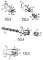
- Figure 1is an elevational view of a first embodiment of a spinal osteosynthesis device according to the invention, corresponding to a lumbo-sacral assembly.
- Figure 2is a perspective view on an enlarged scale, of a pedicle bone anchor hook which can be part of the device of Fig.1.
- Figure 3is an enlarged perspective view similar to Fig.2, of a laminar hook and its expansion screw.
- Figure 4is an exploded perspective view on an enlarged scale of a bone anchoring element according to a third embodiment, consisting of a pedicle screw and its expansion screw.
- Figure 5is a mid-sectional mid-elevational view of the head of the screw of Fig.4 in which has been driven the expansion screw.
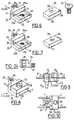
- Figure 6is an exploded perspective view of the three constituent parts of a bone anchor connector forming part of the device of Fig.1.
- Figure 7is a perspective view of an alternative embodiment of the connector of Fig.6.
- Figure 8is a perspective view of the connector of Fig.6 assembled with two flexible rods.
- Figure 9is a partial sectional view in longitudinal elevation of the connector of Fig.8 equipped with a bone anchor screw.
- FIG. 10is a top plan view of the connector of FIGS. 8 and 9.
- FIG. 11is a perspective view on an enlarged scale of a sacred fixing connector forming part of the device of FIG. 1, and of the looped rod on this connector.
- Figure 12is a longitudinal sectional view of the connector of Fig.11 along 12-12 of Fig.14, in a plane containing the parallel axes, of the two bores of this connector.
- Figure 13is a top plan view of the connector of Fig.11.
- Figure 14is an end view along arrow K of Fig.13.
- Figure 15is an exploded perspective view of another embodiment of the bone anchor.
- Figures 16 and 17are perspective views on an enlarged scale of two embodiments of a front support plate.
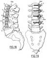
- Figure 18is an elevational view of a prior instrumentation comprising support plates according to the embodiment of Fig.16.
- Figure 19is a rear elevational view of the anterior instrumentation of Fig. 18.
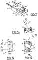
- FIG. 20is a view in longitudinal elevation of a double connector provided with bone anchoring screws, this double connector being able to form a bridge over a fractured vertebra.
- Figure 21is a plan view of the two constituent plates of the connector of Fig. 19.
- FIG. 22is a side elevation view of a posterior instrumentation for fractured vertebrae, placed on the corresponding part of the spine and comprising a double connector according to FIGS. 20 and 21.
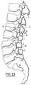
- FIG. 23is a sagittal elevation view of a lumbar instrumentation made up of bone anchoring elements of the pedicle and laminar hook type in accordance with FIGS. 2 and 3.
- Figure 24is a partial sectional view of the connector of Figs 6-10 at the through hole of the bone anchor screw.
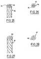
- Figure 25is a partial perspective view on an enlarged scale, of another embodiment of the flexible longitudinal rods of the device according to the invention.
- Figure 26is an end view of the rod of Fig.25.
- Figure 27is a view similar to Fig.25 of an alternative embodiment of the flexible rod.
- Figure 28is an end view of the rod of Fig. 27.
- a spinal osteosynthesis deviceconsisting of lumbosacral instrumentation, extending from the sacrum S, in S1, S2, and extending over the first three lumbar vertebrae L5, L4, L3 .
- This devicecomprises elements 1 for bone anchoring in the sacrum and in the lumbar vertebrae, two flexible longitudinal rods 2 with high elastic limit, of small cross section, roughly parallel to each other and which pass through the connectors (3, 4, 5 , 6) to which they are fixed, and which are themselves mechanically secured to the anchoring elements 1.
- the two rods 2are, in this embodiment, constituted by two parallel parts of a single rod bent into a pin, which pass through the first four connectors 3, 4, 5, 6, the last being anchored in the sacrum in S1.
- the two rodsmeet to form a loop on a round of the sacred connector 7, placed in S2.
- the rods 2can be made of steel with a high elastic limit, for example 650 N / mm 2 , and with high breaking strength (for example 1400 N / mm 2 ), their diameter possibly being approximately 2 or 3mm.
- the bone anchoring elements 1can be either hooks (Fig. 2 and 3) or pedicle screws (Fig. 4 and 5).
- the pedicle hook 8(FIG. 2) comprises a vertebral anchoring part constituted by the hook 9 proper, the edge of which has a notch 9a, and which is connected to a middle part 11 extended by a cylindrical body 12.
- the latterare formed at least two longitudinal slots, namely four slots 13 in the example shown, which delimit between them four branches 14 radially expandable.
- the inner faces of the latterhave a thread 15, and an annular chamfer 16 is formed on the ends of the branches 14.
- an expansion screw 17comprising a threaded rod 18 adapted to be able to be screwed into the body 12, and a head 19 provided with a conical surface 21.
- the lattercan come to bear on the chamfer 16 when the screw 17 is screwed into the threads 15, causing a radial expansion of the branches 14, the external surface of which then assumes a frustoconical shape.
- the conical head 19 of the screw 17has a flat surface 37, bordered by the conical zone 21, and in which is formed a central cavity 38 adapted to receive a tightening key not shown.
- the imprint 38can be both hexagonal and hexalobate in shape.
- the laminar hook 22 of Fig.3differs from the pedicle hook 8 only by its anchor point 23 whose edge is continuous.
- the pedicle screw 24 of FIGS. 4 and 5comprises a threaded rod 25 for bone anchoring, extended on the side opposite its point by a conical part 26 itself followed by a cylindrical body 12 similar to the body 12 of FIG. 2 and 3. At the end of the screwing of the associated screw 17 on the threads 13, its conical surface 21 comes to bear on the chamfer 16 causing a radial expansion of the branches 14 (Fig.5).
- Each of the connectors 3, 4, 5, 6 shown in Fig. 1can be made in accordance with one of the two embodiments shown in Figs. 6 to 10 and 24.
- the connector 3 of Figs. 6, 8, 9 and 10comprises a base 25 with an L-shaped profile, the small branch 25a of the L being extended by a protuberance 26 in which is drilled a tapped hole 27.
- the branch 25aare machined two bores 31, parallel to each other and which cross the branch 25a on either side of the projection 26.
- These bores 31are circular and extend in section on either side of the plane of the large branch 25b of the base 25. They are extended by two parallel semi-circular gutters 32, formed in the surface of the branch 25b of the L, and which extend to the edge of the latter, in the central part of which a tapped hole 33 is drilled.
- the connector 3 (4, 5, 6)also has a flange 28 constituted by a plate in which a central hole 29 is drilled, and which can come to rest on the two branches of the L of the base 25.
- the connector 3is completed by a screw 34, the threaded rod of which passes through the holes 29 and 33 when the flange 28 is placed on the base 25.
- a screw 34the threaded rod of which passes through the holes 29 and 33 when the flange 28 is placed on the base 25.
- On one side of the flange 28are machined two semi-circular and parallel gutters 35, which are positioned so that when the flange 28 is placed in abutment on the large branch 25b of the base 25, these gutters 35 are complementary to the semicircular gutters 32 to form circular bores, in which the rods 2 can take place.
- the hole 27is dimensioned to be able to receive the body 12 of the anchoring element 8, 22 or 24, a screw 24 being shown engaged in the hole 27 in Figs. 9 and 10.
- the screw 17When the screw 17 is screwed into the body 12, it undergoes a radial expansion (Fig. 5) and its branches 14 are strongly applied to the wall of the hole 27, consequently securing the connector 3 and the anchoring element 8, 22 or 24.
- the radial expansion of the branches 14is caused by the force exerted by the conical zone 21 of the screw 17 on the chamfer 16 of the same inclination.
- the external surface of the body 12advantageously has roughness 36 (Fig. 4) making it rough, which promotes the joining of the body 12 with the connector.
- a helical groove 20is also provided in the hole 27 of the connector to improve the mechanical connection of the bone anchoring element / connector.
- the radial forces applied to the walls of the projection 26 by tightening the screw 17are symbolized by the arrows F in FIGS. 9 and 10.
- the longitudinal elements 2Before final tightening by screw 34, the longitudinal elements 2 can slide or translate and rotate around their axis, which is of interest during their installation, because this makes it possible to adjust the interval between two bone anchors, to twist, to bend the assembly of flexible rods + connectors in all positions to adapt to the anchoring elements and facilitate their introduction into the hole 27 of the connector. Once this interval has been adjusted, the complete connection between the connector 3 and the longitudinal rods 2 is ensured by tightening the flange 28 using the screw 34.
- the connector 3adiffers from the connector 3 only in that the bores 38 and the gutters 39, 41 respectively formed on the base 25 and on the flange 28, have an oblong section.
- the major axis of these oblong sectionsextends perpendicularly to the face of the branch 25b of the base 25 and to the corresponding face of the flange 28.
- the oblong shape of the bores 38 and the gutters 39, 41has the advantage of increasing the inertia of the corresponding oblong rods (not shown), and therefore the resistance to bending in the plane passing through the axis of the anchor and parallel to the longitudinal rods.
- the sacred attachment connector 7(FIG. 11) comprises, at one of its ends, a clearance 42 delimiting a rounded shoulder 43, preferably semi-circular, extended by two parallel bores 31 which pierce the connector 7 right through.
- the two longitudinal rods 2 passing through the bores 31are connected by a loop 2a bearing on the shoulder 43, and with which they therefore form a single longitudinal rod.
- two bores 44are pierced, to receive screws (not shown) (such as 24) of sacred attachment.
- the axes XX of the bores 44are parallel and their projections in a longitudinal axial plane (P) of the connector 7 have an inclination (A) on perpendiculars to the faces of the connector contained in said plane (Fig. 12 and 14).
- the axes XXhave an inclination (B) on the axial plane (P) (Fig. 12).
- the angle Acan for example be of the order of 15 °, while B can be around 30 °, these values of course not being limiting.
- the angle Bcan be oriented to the left or to the right, in order to differentiate a left sacred grip from a right sacred grip.
- the bores 44allow the flexible connecting elements 2 to be looped over the rounding 43.
- This arrangementstabilizes and arthrodeses the area of the spine consisting of the lumbar and sacrum, essentially S1 and S2. Its placement is carried out using pedicle screws 24 for the lumbar region and the vertebra S1, and sacred screws 24 for the vertebra S2. These screws constitute the bone anchors, the sacred screws being bone screws having a diameter for example of 3.5 mm, commonly used in orthopedic surgery.
- the longitudinal rods 2are in fact formed, as already indicated, by a single looped rod on the sacred connector 7, the two branches of the loop 2a, constituted by the rods 2, then being threaded into the connectors 3, 4, 5, 6.
- the entire instrumentationis made integral with the spine by pedicle screws and sacred in S2.
- the entire devicecan be bent to make its curvature coincide with the curvature of the spine.
- the deviceis bilateral, only the right side being shown in Fig.1.
- the surgical technique for placing the deviceis as follows.
- the screwed implants or anchorsare first installed by the pedicles and in S1.
- the implantation of the screwsis done "straight ahead" or more laterally on the root of the transverse, so as to converge the two pedicle screws of the same vertebra.
- the sacred fixing connector 7 and the connectors 3, 4 ... for the pedicle and S1 screwsare placed on the flexible connecting elements 2.
- the flanges 28are not tightened, in order to allow their adjustment according to the intervals from vertebra to vertebra, or from pedicle screw to pedicle screw and allow great flexibility. All of the flexible longitudinal elements 2 and connectors 3 ... are then bent to adapt to the curvature of the spine (lordosis or kyphosis).
- the introductionis then carried out by threading the connectors on the screw heads 24.
- the expansion screws 17are tightened as the flexible rod assembly 2- connectors 3, 4 .. are introduced, the operation being carried out from the functional element located highest on the spine towards the sacrum. Once all the connectors have been inserted and locked in the screw heads, the sacred screws of S2 are placed in the specific sacred connector 7.
- the opposite sideis instrumented identically.
- the reduction or correction operationsare then carried out stage by stage, with locking of the flanges respective.
- This maneuveris made starting from the sacrum unilaterally or bilaterally by bringing the connectors apart or by spacing them with appropriate ancillary equipment.
- the graftsare then placed between the different spaces left by the instrumentation in order to perform the arthrodesis.
- the heads 12 of the anchor screws 24are devoid of an axial stop, it is possible, as a variant, to proceed as indicated below.
- the screw 48 shown in Fig. 15is particularly suitable for certain pathologies of the spine, such as spondylolistesis, spondylolysis.
- first threaded rod 49 for bone anchoringof the same type as the rod 25 of the pedicle screws 24, and a second threaded rod 51 in the same axis as the rod 49, from which it is separated by a head 52.
- the rod 51is adapted to receive a nut 53 possibly provided with an enlarged bearing surface 54.
- the screw 48is used with a connector such as 3, 4 ... or a double connector plate 61 ( Fig. 20-21) which will be described later.
- the screwing of the nut 53 bearing on the connector 3 ... or the double connector plate 61causes displacement of the vertebra from front to back along the sagittal plane.
- the surgeoncuts the protruding part of the threaded rod 51.
- anterior instrumentationfirst anterior instrumentation
- the device according to the inventionis compatible with this type, first and for installation. However, it is then advantageously supplemented by anterior support plates 55a or 55b (Fig. 16 and 17) making it possible to avoid the driving in of the corresponding body screws 24 (Fig. 19) and to obtain better alignment of the connectors 3, 4, 5, 6 (the device not having in this use a connector 7 for sacred fixation).
- the vertebral bodyhas a concavity on its periphery which sometimes makes it difficult to put in place material.
- Low resistance of the peripheral cortexalso justifies widening the support on the body and avoiding direct contact with the cone 26 of the screw 24.
- each support plate 55is provided with conical pins 56, striated or not, ensuring its positioning and its stability as long as the body screw 24 is not put in place.
- Each plate 55is pierced with a central hole 57 for the passage of the body screw 24.
- the plate 55is either rigid (plate 55a of FIG. 15) and for this reason of sufficient thickness, with a curve 58 adapted to the concavity of the vertebra, is flexible (plate 55b of Fig.16), and in this case thinner than the plate 55a, in order to be able to adapt to the concavity of the vertebra.
- the double connector 61comprises two plates 62 and 63. These two plates have an appropriate bending in order to respect the anatomical curvature of the patient, and each comprise a terminal flange 65 provided with a clamping element (screw) 66 allowing, in a similar manner to what has been described above, to block the flexible rods 2 in their bores 67 formed in the base 68 for supporting the respective flanges 65.
- these bases 68are each pierced with a hole 69 for passage of the rod threaded of the locking screw 66, in addition to the holes 64 for passage of the rods of the bone anchor screws 24.
- Each plate 62, 63further comprises a respective elongated end portion 71, 72, connected to the terminal base 68 by a connector 73, 74.
- the latterhas a recess 75 allowing the end 72 to come to be applied on the surface of the end 71 of the plate 62.
- In the end 72is arranged an oblong hole 76, and in the elongated end 71 is provided at least one hole 77 (two holes 77 in the example shown) of such so that the oblong hole 76 can be placed opposite the holes 77.
- the assembly of the two plates 62 and 63can thus be achieved by means of two screws 78 passing through the oblong hole 76 and the holes 77 to block the two plates one on top of the other (Fig. 20).
- Asperitiesare formed on the surfaces of the plates 62, 63 in mutual support, that is to say the surfaces of the elongated ends 71 and 72. In the example described, these asperities are formed by notches 79 formed around the hole oblong 76 and holes 77.
- the oblong hole 76makes it possible to adjust the relative position of the two plates 62, 63, and the asperities 79 ensure the relative stability of the two plates in translation and in rotation.
- hooks 8 and 22are used when appropriate, the assemblies illustrated in the drawings being provided only by way of examples.
- Figs. 25 and 26illustrate another embodiment of the longitudinal flexible rods, each here constituted, not by a solid rod such as 2, but by an assembly of wires 85 forming a strand 86.
- the strand 86is thus produced by assembly 7 threads 85, and can be shrunk.
- the rods or strands 86must take up the traction and compression forces and allow a certain flexibility to resume the imposed displacements.
- the use of a strand or a solid rodcan improve the resistance to fatigue by bending of the longitudinal element.
- the rod 86may have a diameter for example of 2mm or 2.5mm. It is obvious that a strand, for example of 7 wires, will have reduced wire diameters, which will give it great flexibility.
- the strand 87is constituted by the assembly of 7 wires 88 (a central wire and six peripheral wires) re-woven to increase the metal cross-section and the rigidity of the strand.
- the strands 86, 87can comprise a variable number of wires, and can be produced for example from 316L stainless steel with high elastic limit.
- This devicecan be used in posterior or anterior approach. All the rods and connectors, thanks to the flexibility of the rods, make it possible to adapt easily and without constraint, to any positioning of the bone anchoring elements.
- the fixing by clamping of the connectors on the rodsstiffens the whole while preserving a certain elasticity with the instrumentation by the mechanical characteristics of the rods, thus favoring the taking of the bone graft associated with osteosynthesis.
- the vertebral screwscan be introduced before or through the connecting elements.
Landscapes
- Health & Medical Sciences (AREA)
- Orthopedic Medicine & Surgery (AREA)
- Life Sciences & Earth Sciences (AREA)
- Surgery (AREA)
- Neurology (AREA)
- Heart & Thoracic Surgery (AREA)
- Engineering & Computer Science (AREA)
- Biomedical Technology (AREA)
- Nuclear Medicine, Radiotherapy & Molecular Imaging (AREA)
- Medical Informatics (AREA)
- Molecular Biology (AREA)
- Animal Behavior & Ethology (AREA)
- General Health & Medical Sciences (AREA)
- Public Health (AREA)
- Veterinary Medicine (AREA)
- Surgical Instruments (AREA)
- Prostheses (AREA)
Abstract
Description
Translated fromFrenchLa présente invention a pour objet un dispositif d'ostéosynthèse rachidienne destiné au traitement des scolioses, des tumeurs, des fractures et des pathologies dégénératives.The present invention relates to a spinal osteosynthesis device intended for the treatment of scoliosis, tumors, fractures and degenerative pathologies.
L'ostéosynthèse rachidienne est actuellement réalisée principalement par des dispositifs utilisant des plaques ou des tiges rigides.Spinal osteosynthesis is currently carried out mainly by devices using rigid plates or rods.
On peut citer comme exemples :
les plaques de Steffee, la technique de WILTSE, le mille pattes de Roy Camille, la technique CD, la technique du Texas Scottish Right Hospital.As examples, we can cite:
Steffee plaques, WILTSE technique, Roy Camille's millipede, CD technique, Texas Scottish Right Hospital technique.
Ces dispositifs posent généralement des problèmes dans la mise en place des plaques ou des tiges sur les implants d'ancrage osseux. En effet, le positionnement de ces ancrages n'étant pas rectiligne, ni de même orientation dans le plan sagittal, notamment en ce qui concerne les vis vertébrales, il est nécessaire de placer les plaques ou les tiges en force, ce qui est préjudiciable à la bonne tenue des ancrages, ou alors de conformer les tiges, par exemple pour pouvoir réaliser la fixation des éléments d'ancrage.These devices generally pose problems in the positioning of the plates or rods on the bone anchoring implants. Indeed, the positioning of these anchors is not straight, nor of the same orientation in the sagittal plane, in particular with regard to the vertebral screws, it is necessary to place the plates or the rods in force, which is detrimental to the good strength of the anchors, or to conform the rods, for example in order to be able to fix the anchoring elements.
Avec ces dispositifs, la réduction est souvent difficile par le fait que l'on doit réduire en même temps que l'on fixe les ancrages osseux aux plaques ou aux tiges. Cette réduction se fait difficilement de manière souple.With these devices, reduction is often difficult by the fact that one must reduce at the same time as one fixes the bone anchors to the plates or to the rods. This reduction is difficult to do flexibly.
De plus la courbure des tiges ou des plaques doit généralement être réalisée avant la mise en place sur les éléments d'ancrages osseux, ce qui limite l'optimisation de la réduction.In addition, the curvature of the rods or of the plates must generally be carried out before placement on the bone anchoring elements, which limits the optimization of the reduction.
De l'avis de nombreux chirurgiens, la rigidité trop importante des instrumentations agit de façon néfaste sur la rapidité de la consolidation osseuse de la greffe associée à l'ostéosynthèse rachidienne.In the opinion of many surgeons, the excessive rigidity of the instruments has a detrimental effect on the speed of bone consolidation of the graft associated with spinal osteosynthesis.
On connaît par ailleurs, par le US-A-5 057 109, des éléments d'ancrage osseux vertébral conformes au préambule de la revendication 1.Furthermore, US-A-5,057,109 discloses vertebral bone anchoring elements in accordance with the preamble of
L'invention a pour but de proposer un dispositif d'ostéosynthèse à fixation segmentaire utilisable en voie postérieure en bilatéral et en voie antérieure, agencé de manière à :
- faciliter la mise en place des implants grâce à la flexibilité des liaisons longitudinales s'adaptant à tout positionnement des éléments d'ancrage;
- permettre d'affiner la réduction par simple mouvement d'écartement ou de rapprochement et de rigidifier le montage progressivement segment par segment;
- préserver une élasticité suffisante de manière à favoriser la fusion osseuse de la greffe associée à l'ostéosynthèse;
- obtenir une instrumentation réduite en encombrement.
- facilitate the placement of the implants thanks to the flexibility of the longitudinal links adapting to any positioning of the anchoring elements;
- make it possible to refine the reduction by simple spacing or approximation movement and to stiffen the mounting progressively segment by segment;
- maintain sufficient elasticity so as to promote bone fusion of the graft associated with osteosynthesis;
- obtain instrumentation reduced in size.
Le dispositif d'ostéosynthèse rachidienne selon l'invention est conforme à la partie caractérisante de la revendication 1.The spinal osteosynthesis device according to the invention is in accordance with the characterizing part of
Les tiges flexibles sont de section circulaire ou non, par exemple oblongue et fabriquées en matériau biocompatible à haute limite élastique et haute résistance à la rupture. De plus, ces tiges flexibles peuvent être des tiges pleines ou bien des assemblages de fils comme par exemple des torons.The flexible rods are of circular section or no, for example oblong and made of biocompatible material with high elastic limit and high breaking strength. In addition, these flexible rods can be solid rods or else assemblies of wires such as, for example, strands.
On comprend qu'un tel dispositif d'étaiement du rachis préserve une certaine élasticité dans la zone arthrodésée, grâce à la mise en oeuvre de tiges métalliques flexibles à haute limite élastique, qui traversent un nombre approprié de connecteurs eux-mêmes solidement ancrés aux vertèbres par des éléments tels que vis et crochets.It is understood that such a shoring device for the spine preserves a certain elasticity in the arthrodesic zone, thanks to the use of flexible metal rods with high elastic limit, which pass through an appropriate number of connectors themselves firmly anchored to the vertebrae by elements such as screws and hooks.
Les tiges métalliques ont une section faible par rapport aux tiges des instrumentations postérieures utilisées jusqu'à présent, et une inertie appropriée pour donner l'élasticité à l'ostéosynthèse favorable à la bonne greffe osseuse.The metal rods have a small cross-section compared to the rods of the posterior instruments used until now, and an appropriate inertia to give the elasticity to the osteosynthesis favorable to good bone grafting.
Suivant d'autres caractéristiques de l'invention:
- chaque connecteur comprend un socle dans lequel sont ménagés deux alésages traversés par des tiges flexibles correspondantes, ainsi qu'un trou de réception du corps expansible d'un élément d'ancrage, et ledit connecteur comprend également des moyens de fixation des tiges au socle.
- lesdits moyens de fixation comprennent une bride dans une face de laquelle sont agencées des gouttières complémentaires de gouttières correspondantes ménagées dans une face du socle dans le prolongement des alésages, de telle sorte que les tiges flexibles soient logées dans les gouttières conjuguées de la bride et du socle, la bride étant pourvue d'un organe de serrage sur le socle et de blocage des tiges dans leurs alésages et gouttières, tel qu'une vis traversant le trou lisse de la bride et le trou taraudé du socle.
- each connector comprises a base in which are formed two bores crossed by corresponding flexible rods, as well as a hole for receiving the expansible body of an anchoring element, and said connector also comprises means for fixing the rods to the base.
- said fixing means comprise a flange in one face of which are arranged complementary gutters of corresponding gutters formed in one face of the base in the extension of the bores, so that the flexible rods are housed in the combined gutters of the flange and the base, the flange being provided with a clamping member on the base and blocking the rods in their bores and gutters, such as a screw passing through the smooth hole of the flange and the hole threaded from the base.
L'invention sera maintenant décrite en référence aux dessins annexés qui en illustrent plusieurs formes de réalisation à titre d'exemples non limitatifs.The invention will now be described with reference to the accompanying drawings which illustrate several embodiments thereof by way of non-limiting examples.
La figure 1 est une vue en élévation d'une première forme de réalisation d'un dispositif d'ostéosynthèse rachidienne selon l'invention, correspondant à un montage lombo-sacré.Figure 1 is an elevational view of a first embodiment of a spinal osteosynthesis device according to the invention, corresponding to a lumbo-sacral assembly.
La figure 2 est une vue en perspective à échelle agrandie, d'un crochet pédiculaire d'ancrage osseux pouvant faire partie du dispositif de la Fig.1.Figure 2 is a perspective view on an enlarged scale, of a pedicle bone anchor hook which can be part of the device of Fig.1.
La figure 3 est une vue en perspective à échelle agrandie similaire à la Fig.2, d'un crochet laminaire et de sa vis d'expansion.Figure 3 is an enlarged perspective view similar to Fig.2, of a laminar hook and its expansion screw.
La figure 4 est une vue en perspective éclatée à échelle agrandie d'un élément d'ancrage osseux selon un troisième mode de réalisation, constitué par une vis pédiculaire et sa vis d'expansion.Figure 4 is an exploded perspective view on an enlarged scale of a bone anchoring element according to a third embodiment, consisting of a pedicle screw and its expansion screw.
La figure 5 est une vue mi-élévation mi-coupe axiale de la tête de la vis de la Fig.4 dans laquelle a été enfoncée la vis d'expansion.Figure 5 is a mid-sectional mid-elevational view of the head of the screw of Fig.4 in which has been driven the expansion screw.
La figure 6 est une vue en perspective éclatée des trois parties constitutives d'un connecteur d'ancrage osseux faisant partie du dispositif de la Fig.1.Figure 6 is an exploded perspective view of the three constituent parts of a bone anchor connector forming part of the device of Fig.1.
La figure 7 est une vue en perspective d'une variante de réalisation du connecteur de la Fig.6.Figure 7 is a perspective view of an alternative embodiment of the connector of Fig.6.
La figure 8 est une vue en perspective du connecteur de la Fig.6 assemblé à deux tiges flexibles.Figure 8 is a perspective view of the connector of Fig.6 assembled with two flexible rods.
La figure 9 est une vue en coupe partielle et élévation longitudinale du connecteur de la Fig.8 équipé d'une vis d'ancrage osseux.Figure 9 is a partial sectional view in longitudinal elevation of the connector of Fig.8 equipped with a bone anchor screw.
La figure 10 est une vue de dessus en plan du connecteur des Fig.8 et 9.FIG. 10 is a top plan view of the connector of FIGS. 8 and 9.
La figure 11 est une vue en perspective à échelle agrandie d'un connecteur de fixation sacrée faisant partie du dispositif de la Fig.1, et de la tige bouclée sur ce connecteur.FIG. 11 is a perspective view on an enlarged scale of a sacred fixing connector forming part of the device of FIG. 1, and of the looped rod on this connector.
La figure 12 est une vue en coupe longitudinale du connecteur de la Fig.11 suivant 12-12 de la Fig.14, dans un plan contenant les axes parallèles, des deux alésages de ce connecteur.Figure 12 is a longitudinal sectional view of the connector of Fig.11 along 12-12 of Fig.14, in a plane containing the parallel axes, of the two bores of this connector.
La figure 13 est une vue de dessus en plan du connecteur de la Fig.11.Figure 13 is a top plan view of the connector of Fig.11.
La figure 14 est une vue en bout suivant la flèche K de la Fig.13.Figure 14 is an end view along arrow K of Fig.13.
La figure 15 est une vue en perspective éclatée d'une autre forme de réalisation de l'élément d'ancrage osseux.Figure 15 is an exploded perspective view of another embodiment of the bone anchor.
Les figures 16 et 17 sont des vues en perspective à échelle agrandie de deux modes de réalisation d'une plaque d'appui antérieur.Figures 16 and 17 are perspective views on an enlarged scale of two embodiments of a front support plate.
La figure 18 est une vue en élévation d'une instrumentation antérieure comportant des plaques d'appui selon le mode de réalisation de la Fig.16.Figure 18 is an elevational view of a prior instrumentation comprising support plates according to the embodiment of Fig.16.
La figure 19 est une vue en élévation postérieure de l'instrumentation antérieure de la Fig.18.Figure 19 is a rear elevational view of the anterior instrumentation of Fig. 18.
La figure 20 est une vue en élévation longitudinale d'un connecteur double muni de vis d'ancrage osseux, ce connecteur double pouvant former un pont au-dessus d'une vertèbre fracturée.FIG. 20 is a view in longitudinal elevation of a double connector provided with bone anchoring screws, this double connector being able to form a bridge over a fractured vertebra.
La figure 21 est une vue en plan des deux plaques constitutives du connecteur de la Fig.19.Figure 21 is a plan view of the two constituent plates of the connector of Fig. 19.
La figure 22 est une vue en élévation latérale d'une instrumentation postérieure pour vertèbres fracturées, mise en place sur la partie correspondante du rachis et comportant un connecteur double selon les Fig.20 et 21.FIG. 22 is a side elevation view of a posterior instrumentation for fractured vertebrae, placed on the corresponding part of the spine and comprising a double connector according to FIGS. 20 and 21.
La figure 23 est une vue en élévation sagittale d'une instrumentation lombaire constituée d'éléments d'ancrage osseux du type crochets pédiculaires et laminaires conformes aux Fig.2 et 3.FIG. 23 is a sagittal elevation view of a lumbar instrumentation made up of bone anchoring elements of the pedicle and laminar hook type in accordance with FIGS. 2 and 3.
La figure 24 est une vue en coupe partielle du connecteur des Fig.6 à 10 au niveau du trou de passage de la vis d'ancrage osseux.Figure 24 is a partial sectional view of the connector of Figs 6-10 at the through hole of the bone anchor screw.
La figure 25 est une vue en perspective partielle à échelle agrandie, d'une autre forme de réalisation des tiges longitudinales flexibles du dispositif selon l'invention.Figure 25 is a partial perspective view on an enlarged scale, of another embodiment of the flexible longitudinal rods of the device according to the invention.
La figure 26 est une vue en bout de la tige de la Fig.25.Figure 26 is an end view of the rod of Fig.25.
La figure 27 est une vue analogue à la Fig.25 d'une variante de réalisation de la tige flexible.Figure 27 is a view similar to Fig.25 of an alternative embodiment of the flexible rod.
La figure 28 est une vue en bout de la tige de la Fig.27.Figure 28 is an end view of the rod of Fig. 27.
On voit à la Fig.1 un dispositif d'ostéosynthèse rachidienne constitué par une instrumentation lombo-sacrée, s'étendant à partir du sacrum S, en S1, S2, et s'étendant sur les trois premières vertèbres lombaires L5, L4, L3. Ce dispositif comprend des éléments 1 d'ancrage osseux dans le sacrum et dans les vertèbres lombaires, deux tiges longitudinales flexibles 2 à haute limite élastique, de section faible, à peu près parallèles entre elles et qui traversent les connecteurs (3, 4, 5, 6) auxquels elles sont fixées, et qui sont eux-mêmes mécaniquement solidarisés avec les éléments d'ancrage 1.We see in Fig. 1 a spinal osteosynthesis device consisting of lumbosacral instrumentation, extending from the sacrum S, in S1, S2, and extending over the first three lumbar vertebrae L5, L4, L3 . This device comprises
Les deux tiges 2 sont, dans cette réalisation, constituées par deux parties parallèles d'une seule tige recourbée en épingle, qui traversent les quatre premiers connecteurs 3, 4, 5, 6, le dernier étant ancré dans le sacrum en S1. Les deux tiges se rejoignent en formant une boucle sur un arrondi du connecteur sacré 7, placé en S2.The two
Les tiges 2 peuvent être en acier à haute limite élastique, par exemple 650 N/mm2, et à haute résistance à la rupture (par exemple 1400 N/mm2) leur diamètre pouvant être de 2 ou 3mm environ.The
Les éléments d'ancrage osseux 1 peuvent être, soit des crochets (Fig.2 et 3), soit des vis pédiculaires (Fig.4 et 5).The
Le crochet pédiculaire 8 (Fig.2) comprend une partie d'ancrage vertébral constituée par le crochet 9 proprement dit, dont le bord présente une entaille 9a, et qui est reliée à une partie médiane 11 prolongée par un corps cylindrique 12. Dans ce dernier sont ménagées au moins deux fentes longitudinales, à savoir quatre fentes 13 dans l'exemple représenté, qui délimitent entre elles quatre branches 14 expansibles radialement. Les faces intérieures de ces dernières présentent un taraudage 15, et un chanfrein annulaire 16 est formé sur les extrémités des branches 14.The pedicle hook 8 (FIG. 2) comprises a vertebral anchoring part constituted by the hook 9 proper, the edge of which has a
Enfin le crochet 8 est complété par une vis d'expansion 17 comportant une tige filetée 18 adaptée pour pouvoir se visser dans le corps 12, et une tête 19 pourvue d'une surface conique 21. Cette dernière peut venir en appui sur le chanfrein 16 lorsque la vis 17 est vissée dans les taraudages 15, en provoquant une expansion radiale des branches 14, dont la surface externe affecte alors une forme tronconique.Finally, the
La tête conique 19 de la vis 17 présente une surface plane 37, bordée par la zone conique 21, et dans laquelle est formée une empreinte centrale 38 adaptée pour recevoir une clé de serrage non représentée. L'empreinte 38 peut être de forme à la fois hexagonale et hexalobée.The
Le crochet laminaire 22 de la Fig.3 diffère du crochet pédiculaire 8 uniquement par sa pointe d'ancrage 23 dont le bord est continu.The
La vis pédiculaire 24 des Fig.4 et 5 comporte une tige filetée 25 d'ancrage osseux, prolongée du côté opposé à sa pointe par une partie conique 26 elle-même suivie par un corps cylindrique 12 similaire au corps 12 des Fig.2 et 3. A la fin du vissage de la vis 17 associée sur les taraudages 13, sa surface conique 21 vient s'appuyer sur le chanfrein 16 en provoquant une expansion radiale des branches 14 (Fig.5).The
Chacun des connecteurs 3, 4, 5, 6 représentés à la Fig.1 peut être réalisé conformément à l'un des deux modes de réalisation représentés aux Fig.6 à 10 et 24.Each of the
Le connecteur 3 des Fig.6, 8, 9 et 10 comprend un socle 25 à profil en L, la petite branche 25a du L étant prolongée par une excroissance 26 dans laquelle est percé un trou taraudé 27. Dans la branche 25a sont usinés deux alésages 31, parallèles l'un à l'autre et qui traversent la branche 25a de part et d'autre de l'excroissance 26. Ces alésages 31 sont circulaires et s'étendent en section de part et d'autre du plan de la grande branche 25b du socle 25. Ils se prolongent par deux gouttières parallèles 32, semi-circulaires, ménagées dans la surface de la branche 25b du L, et qui s'étendent jusqu'au bord de cette dernière, dans la partie centrale de laquelle est percé un trou taraudé 33. Le connecteur 3 (4, 5, 6) comporte également une bride 28 constituée par une plaquette dans laquelle est percé un trou central 29, et qui peut venir se placer en appui sur les deux branches du L du socle 25.The
Le connecteur 3 est complété par une vis 34 dont la tige filetée traverse les trous 29 et 33 lorsque la bride 28 est placée sur le socle 25. Sur l'une des faces de la bride 28 sont usinées deux gouttières 35 semi-circulaires et parallèles, et qui sont positionnées de telle sorte que lorsque la bride 28 est placée en appui sur la grande branche 25b du socle 25, ces gouttières 35 soient complémentaires des gouttières semi-circulaires 32 pour former des alésages circulaires, dans lesquels peuvent prendre place les tiges 2.The
Le trou 27 est dimensionné pour pouvoir recevoir le corps 12 de l'élément d'ancrage 8, 22 ou 24, une vis 24 étant représentée engagée dans le trou 27 aux Fig.9 et 10. Lorsque la vis 17 est vissée dans le corps 12, celui-ci subit une expansion radiale (Fig.5) et ses branches 14 sont fortement appliquées sur la paroi du trou 27, en solidarisant par conséquent le connecteur 3 et l'élément d'ancrage 8, 22 ou 24. L'expansion radiale des branches 14 est provoquée par la force exercée par la zone conique 21 de la vis 17 sur le chanfrein 16 de même inclinaison. La surface extérieure du corps 12 présente avantageusement des aspérités 36 (Fig.4) la rendant rugueuse, ce qui favorise la solidarisation du corps 12 avec le connecteur. Une rainure hélicoïdale 20 est également ménagée dans le trou 27 du connecteur pour améliorer la liaison mécanique élément d'ancrage osseux/connecteur. Les forces radiales appliquées sur les parois de l'excroissance 26 par le serrage de la vis 17 sont symbolisées par les flèches F sur les Fig.9 et 10.The
Les tiges flexibles élastiques 2, une fois convenablement positionnées dans les alésages 31 et les gouttières 32, 35, peuvent être fixées au connecteur 3 par vissage de la vis 34 dans les trous 29 et 33 (Fig.8 et 9). Avant serrage définitif par la vis 34, les éléments longitudinaux 2 peuvent coulisser ou translater et tourner autour de leur axe, ce qui présente un intérêt lors de leur mise en place, car cela permet de régler l'intervalle entre deux ancrages osseux, de vriller, de courber l'ensemble tiges flexibles + connecteurs dans toutes les positions pour s'adapter aux éléments d'ancrage et faciliter leur introduction dans le trou 27 du connecteur. Une fois cet intervalle ajusté, la liaison complète entre le connecteur 3 et les tiges longitudinales 2 est assurée par serrage de la bride 28 grâce à la vis 34.The flexible
Dans la variante d'exécution de la Fig.7, le connecteur 3a diffère du connecteur 3 uniquement par le fait que les alésages 38 et les gouttières 39, 41 respectivement formées sur le socle 25 et sur la bride 28, ont une section oblongue. Le grand axe de ces sections oblongues s'étend perpendiculairement à la face de la branche 25b du socle 25 et à la face correspondante de la bride 28. La forme oblongue des alésages 38 et des gouttières 39, 41 présente l'avantage d'augmenter l'inertie des tiges oblongues correspondantes (non représentées), et donc la résistance à la flexion dans le plan passant par l'axe de l'ancrage et parallèle aux tiges longitudinales.In the variant embodiment of FIG. 7, the
Les éléments de l'instrumentation décrite ci-dessus, une fois assemblés et mis en place sur un segment rachidien, se présentent comme illustré à la Fig.23 à titre d'exemple.The elements of the instrumentation described above, once assembled and placed on a spinal segment, are presented as illustrated in Fig. 23 by way of example.
Le connecteur 7 de fixation sacrée (Fig.11) comporte, à une de ses extrémités, un dégagement 42 délimitant un épaulement arrondi 43, de préférence semi-circulaire, prolongé par deux alésages parallèles 31 qui percent de part en part le connecteur 7. Les deux tiges longitudinales 2 traversant les alésages 31 sont reliées par une boucle 2a en appui sur l'épaulement 43, et avec laquelle elles forment donc une tige longitudinale unique.The sacred attachment connector 7 (FIG. 11) comprises, at one of its ends, a
Dans le corps du connecteur 7, sont percés deux alésages 44, pour recevoir des vis non représentées (telles que 24) de fixation sacrée. Les axes XX des alésages 44 sont parallèles et leurs projections dans un plan axial longitudinal (P) du connecteur 7 ont une inclinaison (A) sur des perpendiculaires aux faces du connecteur contenues dans ledit plan (Fig.12 et 14). De plus les axes XX ont une inclinaison (B) sur le plan axial (P) (Fig.12).In the body of the
L'angle A peut être par exemple de l'ordre de 15°, tandis que B peut être d'environ 30°, ces valeurs n'étant bien entendu pas limitatives. L'angle B peut être orienté à gauche ou à droite, afin de différencier une prise sacrée gauche d'une prise sacrée droite. Les alésages 44 permettent le bouclage sur l'arrondi 43 des éléments de liaison flexibles 2.The angle A can for example be of the order of 15 °, while B can be around 30 °, these values of course not being limiting. The angle B can be oriented to the left or to the right, in order to differentiate a left sacred grip from a right sacred grip. The
La mise en oeuvre et les avantages du montage lombo-sacré illustré à la Fig.1 sont les suivants.The implementation and the advantages of the lumbo-sacral assembly illustrated in Fig.1 are as follows.
Ce montage permet de stabiliser et d'arthrodéser la zone du rachis constituée des lombaires et du sacrum, essentiellement S1 et S2. Sa mise en place est réalisée à l'aide de vis pédiculaires 24 pour la zone lombaire et la vertèbre S1, et de vis sacrées 24 pour la vertèbre S2. Ces vis constituent les ancrages osseux, les vis sacrées étant des vis à os ayant un diamètre par exemple de 3,5mm, utilisées couramment en chirurgie orthopédique.This arrangement stabilizes and arthrodeses the area of the spine consisting of the lumbar and sacrum, essentially S1 and S2. Its placement is carried out using
Les tiges longitudinales 2 sont en fait constituées, comme déjà indiqué, par une seule tige bouclée sur le connecteur sacré 7, les deux branches de la boucle 2a, constituées par les tiges 2, étant ensuite enfilées dans les connecteurs 3, 4, 5, 6. L'ensemble de l'instrumentation est rendu solidaire du rachis par les vis pédiculaires et sacrées en S2. L'ensemble du dispositif peut être cintré pour faire coïncider sa courbure avec la courbure du rachis. Le dispositif est bilatéral, seul le côté droit étant représenté à la Fig.1.The
La technique chirurgicale de mise en place du dispositif est la suivante.The surgical technique for placing the device is as follows.
Les implants vissés ou ancrages sont mis en place dans un premier temps par les pédicules et dans S1. L'implantation des vis se fait "droit devant" ou plus latéralement sur la racine de la transverse, de façon à faire converger les deux vis pédiculaires d'une même vertèbre.The screwed implants or anchors are first installed by the pedicles and in S1. The implantation of the screws is done "straight ahead" or more laterally on the root of the transverse, so as to converge the two pedicle screws of the same vertebra.
Le connecteur de fixation sacrée 7 et les connecteurs 3, 4... pour les vis pédiculaires et de S1 sont mis en place sur les éléments de liaison flexibles 2. Les brides 28 ne sont pas serrées, afin de permettre leur réglage en fonction des intervalles de vertèbre à vertèbre, ou de vis pédiculaire à vis pédiculaire et laisser une grande flexibilité. L'ensemble des éléments longitudinaux flexibles 2 et des connecteurs 3... est alors cintré pour s'adapter à la courbure du rachis (lordose ou cyphose). L'introduction est ensuite réalisée en enfilant les connecteurs sur les têtes de vis 24.The
Les vis d'expansion 17 sont serrées à mesure de l'introduction de l'ensemble tige flexible 2- connecteurs 3, 4.., l'opération étant exécutée à partir de l'élément fonctionnel situé le plus haut sur le rachis vers le sacrum. Une fois l'ensemble des connecteurs introduit et verrouillé dans les têtes de vis, les vis sacrées de S2 sont mises en place dans le connecteur sacré spécifique 7.The expansion screws 17 are tightened as the flexible rod assembly 2-
Le côté opposé est instrumenté de façon identique. Les manoeuvres de réduction ou de correction sont alors réalisées étage par étage, avec verrouillage des brides respectives. Cette manoeuvre est faite en partant du sacrum de façon unilatérale ou bilatérale par rapprochement ou par écartement des connecteurs avec un matériel ancillaire approprié. Les greffons sont alors placés entre les différents espaces laissés par l'instrumentation afin de réaliser l'arthrodèse.The opposite side is instrumented identically. The reduction or correction operations are then carried out stage by stage, with locking of the flanges respective. This maneuver is made starting from the sacrum unilaterally or bilaterally by bringing the connectors apart or by spacing them with appropriate ancillary equipment. The grafts are then placed between the different spaces left by the instrumentation in order to perform the arthrodesis.
Grâce au fait que les têtes 12 des vis d'ancrage 24 sont dépourvues de butée axiale, il est possible de procéder, en variante, comme indiqué ci-dessous.Thanks to the fact that the
Dans la mesure où l'ensemble connecteurs plus éléments 2 de liaison flexible forme un tout, celui-ci peut être posé sur la face postérieure du rachis à la manière d'une plaque d'ostéosynthèse rachidienne. Les vis 24 sont alors introduites au travers des connecteurs laissés libres sur les éléments 2 de liaison flexible, afin d'effectuer l'ancrage pédiculaire. Les vis d'expansion 17 sont alors mises en place et vissées pour rendre les vis 24 solidaires des connecteurs 3. Le reste du montage s'exécute comme indiqué précédemment.Insofar as the set of connectors plus
La vis 48 représentée à la Fig.15 est particulièrement adaptée à certaines pathologies du rachis, telles que spondylolistésis, spondylolyse.The
Elle est à double filetage et comporte donc une première tige filetée 49 d'ancrage osseux, du même type que la tige 25 des vis pédiculaires 24, et une seconde tige filetée 51 dans le même axe que la tige 49, dont elle est séparée par une tête 52. La tige 51 est adaptée pour recevoir un écrou 53 éventuellement pourvu d'une surface d'appui élargie 54. La vis 48 est utilisée avec un connecteur tel que 3, 4... ou une plaque de connecteur double 61 (Fig.20-21) qui sera décrit plus loin. Après ancrage osseux, le vissage de l'écrou 53 en appui sur le connecteur 3... ou la plaque du connecteur double 61, provoque un déplacement de la vertèbre d'avant en arrière suivant le plan sagittal. Enfin le chirurgien coupe la partie de la tige filetée 51 qui dépasse.It is double threaded and therefore includes a first threaded
Certaines pathologies du rachis justifient l'utilisation d'instrumentations d'abord antérieur, dites instrumentations antérieures. Le dispositif selon l'invention est compatible avec ce type d'abord et de mise en place. Toutefois, il est alors avantageusement complété par des plaques d'appui antérieur 55a ou 55b (Fig.16 et 17) permettant d'éviter l'enfoncement des vis corporéales 24 correspondantes (Fig.19) et d'obtenir un meilleur alignement des connecteurs 3, 4, 5, 6 (le dispositif ne comportant pas dans cette utilisation de connecteur 7 de fixation sacrée).Certain pathologies of the spine justify the use of first anterior instrumentation, called anterior instrumentation. The device according to the invention is compatible with this type, first and for installation. However, it is then advantageously supplemented by
En effet, le corps vertébral présente sur sa périphérie une concavité qui rend parfois délicate la mise en place de matériel. Une faible résistance de la corticale périphérique justifie également d'élargir l'appui sur le corps et d'éviter le contact direct du cône 26 de la vis 24.Indeed, the vertebral body has a concavity on its periphery which sometimes makes it difficult to put in place material. Low resistance of the peripheral cortex also justifies widening the support on the body and avoiding direct contact with the
Afin de faciliter sa mise en place, chaque plaque d'appui 55 est pourvue de picots coniques 56, striés ou non, assurant son positionnement et sa stabilité tant que la vis corporéale 24 n'est pas mise en place. Chaque plaque 55 est percée d'un trou central 57 de passage de la vis corporéale 24. La plaque 55 est soit rigide (plaque 55a de la Fig.15) et pour cela d'épaisseur suffisante, avec un galbe 58 adapté à la concavité de la vertèbre, soit souple (plaque 55b de la Fig.16), et dans ce cas de plus faible épaisseur que la plaque 55a, afin de pouvoir s'adapter à la concavité de la vertèbre.In order to facilitate its positioning, each
Les autres éléments de l'instrumentation sont identiques en tous points à ceux de l'instrumentation postérieure décrite ci-dessus, excepté le fait qu'il n'y a pas de plaque ou prise sacrée. L'ensemble du dispositif mis en place sur le rachis est représenté aux Fig.18 et 19.The other elements of the instrumentation are identical in all respects to those of the posterior instrumentation described above, except that there is no sacred plate or socket. The entire device placed on the spine is shown in Figs. 18 and 19.
L'instrumentation de fractures corporéales rend parfois impossible le vissage pédiculaire de la ou des vertèbres fracturées. Il est donc nécessaire de passer un étage ou élément fonctionnel vertébral. Cette fonction est remplie par le connecteur double 61 (Fig.20 et 21) adapté pour former un pont au-dessus d'une vertèbre fracturée.The instrumentation of body fractures sometimes makes it impossible to screw the pedicle of the fractured vertebra (s). It is therefore necessary to pass a floor or vertebral functional element. This function is fulfilled by the double connector 61 (Fig. 20 and 21) adapted to form a bridge over a fractured vertebra.
Le connecteur double 61 comprend deux plaques 62 et 63. Ces deux plaques présentent un cintrage approprié afin de respecter la courbure anatomique du patient, et comportent chacune une bride terminale 65 munie d'un élément (vis) de serrage 66 permettant, de manière similaire à ce qui a été décrit précédemment, de bloquer les tiges flexibles 2 dans leurs alésages 67 ménagés dans le socle 68 d'appui des brides respectives 65. A cet effet ces socles 68 sont percés chacun d'un trou 69 de passage de la tige filetée de la vis de blocage 66, en plus des trous 64 de passage des tiges des vis d'ancrage osseux 24.The
Chaque plaque 62, 63 comprend de plus une partie terminale allongée 71, 72 respective, reliée au socle terminal 68 par un raccord 73, 74. Ce dernier présente un décrochement 75 permettant à l'extrémité 72 de venir s'appliquer sur la surface de l'extrémité 71 de la plaque 62. Dans l'extrémité 72 est agencé un trou oblong 76, et dans l'extrémité allongée 71 est ménagé au moins un trou 77 (deux trous 77 dans l'exemple représenté) de telle sorte que le trou oblong 76 puisse venir se placer en vis-à-vis des trous 77. L'assemblage des deux plaques 62 et 63 peut ainsi être réalisé au moyen de deux vis 78 traversant le trou oblong 76 et les trous 77 pour bloquer les deux plaques l'une sur l'autre (Fig.20).Each
Des aspérités sont formées sur les surfaces des plaques 62, 63 en appui mutuel, c'est-à-dire les surfaces des extrémités allongées 71 et 72. Dans l'exemple décrit, ces aspérités sont constituées par des crantages 79 formés autour du trou oblong 76 et des trous 77.Asperities are formed on the surfaces of the
Le trou oblong 76 permet de régler la position relative des deux plaques 62, 63, et les aspérités 79 assurent la stabilité relative des deux plaques en translation et en rotation.The oblong hole 76 makes it possible to adjust the relative position of the two
Le mode opératoire de mise en place de l'instrumentation comportant des connecteurs doubles 61 (Fig.22) est le suivant.
- a) mise en place des vis pédiculaires 24 et de S1.
- b) mise en place de l'ensemble constitué par les connecteurs simples 3, 4, 5, le connecteur sacré 7 et un connecteur double 61, disposé entre les connecteurs 3
et 4, (le connecteur 61 est dimensionné pour enjamber une vertèbre fracturée L2), par enfilement sur les corps 12 des vis pédiculaires 24, puis on serre ces dernières dans les connecteurs 3, 61, 4, 5. - c) réduction de la fracture par manoeuvre des corps de vis 24 de part et d'autre du foyer de fracture.
- d) fixation et serrage des deux vis 78 de réglage du connecteur double 61.
- e) serrage des
brides 65 de fixation des tiges 2. - f) mise en place des vis 20 en S2.
- a) placement of pedicle screws 24 and S1.
- b) installation of the assembly constituted by the
single connectors sacred connector 7 and adouble connector 61, disposed between theconnectors connector 61 is dimensioned to span a fractured vertebra L2 ), by threading on thebodies 12 of the pedicle screws 24, then the latter are tightened in theconnectors - c) reduction of the fracture by maneuvering the
screw bodies 24 on either side of the fracture center. - d) fixing and tightening of the two
screws 78 for adjusting thedouble connector 61. - e) tightening the
flanges 65 for fixing therods 2. - f)
fitting screws 20 in S2.
Les deux dernières opérations peuvent être permutées.The last two operations can be swapped.
On obtient alors un montage mixte de rigidité accrue dans le foyer de fracture, par l'intermédiaire du connecteur double 61, et plus élastique de part et d'autre du foyer, ce qui assure une stabilité globale du rachis.This gives a mixed assembly of increased rigidity in the fracture focus, via the
Bien entendu on utilise les crochets 8 et 22 lorsque cela est approprié, les montages illustrés aux dessins n'étant fournis qu'à titre d'exemples.Of course, hooks 8 and 22 are used when appropriate, the assemblies illustrated in the drawings being provided only by way of examples.
Les Fig. 25 et 26 illustrent une autre forme de réalisation des tiges flexibles longitudinales, ici constituées chacune, non par une tige pleine telle que 2, mais par un assemblage de fils 85 formant un toron 86. Dans cet exemple le toron 86 est ainsi réalisé par assemblage de 7 fils 85, et peut être rétreint.Figs. 25 and 26 illustrate another embodiment of the longitudinal flexible rods, each here constituted, not by a solid rod such as 2, but by an assembly of
Les tiges ou torons 86 doivent reprendre les efforts en traction et compression et permettre une certaine flexibilité pour reprendre les déplacements imposés. L'utilisation d'un toron ou d'une tige pleine peut améliorer la tenue en fatigue par flexion de l'élément longitudinal. En effet, la tige 86 peut avoir un diamètre par exemple de 2mm ou 2,5mm. Il est évident qu'un toron, par exemple de 7 fils, aura des diamètres de fils réduits, qui lui confèreront une grande flexibilité.The rods or
Dans la variante de réalisation des Fig.27-28, le toron 87 est constitué par l'assemblage de 7 fils 88 (un fil central et six fils périphériques) retréfilés pour accroître la section métallique et la rigidité du toron.In the variant embodiment of FIGS. 27-28, the
Les torons 86, 87 peuvent comporter un nombre variable de fils, et être réalisés par exemple en acier inoxydable 316L à haute limite élastique.The
L'utilisation de tiges pleines 2 ou de torons 86, 87 est identique. L'amélioration de la flexibilité apportée par les torons se fait au détriment de la tenue en compression. Par conséquent le choix d'une tige pleine ou d'un toron, et sa composition, est un compromis en fonction des indications.The use of
Ce dispositif peut être utilisé en abord postérieur ou antérieur. L'ensemble des tiges et des connecteurs, grâce à la flexibilité des tiges, permet de s'adapter aisément et sans contrainte, à tout positionnement des éléments d'ancrage osseux. Le glissement des connecteurs sur les tiges après fixation des éléments d'ancrage osseux à ceux-ci, permet d'affiner la réduction du segment rachidien instrumenté. La fixation par bridage des connecteurs sur les tiges, rigidifie l'ensemble tout en préservant une certaine élasticité à l'instrumentation de par les caractéristiques mécaniques des tiges, favorisant ainsi la prise de la greffe osseuse associée à l'ostéosynthèse.This device can be used in posterior or anterior approach. All the rods and connectors, thanks to the flexibility of the rods, make it possible to adapt easily and without constraint, to any positioning of the bone anchoring elements. The sliding of the connectors on the rods after fixation of the bone anchoring elements to them, makes it possible to refine the reduction of the instrumented spinal segment. The fixing by clamping of the connectors on the rods, stiffens the whole while preserving a certain elasticity with the instrumentation by the mechanical characteristics of the rods, thus favoring the taking of the bone graft associated with osteosynthesis.
Les vis vertébrales peuvent être introduites avant les éléments de liaison ou à travers.The vertebral screws can be introduced before or through the connecting elements.
Claims (16)
- A spinal osteosynthesis device comprising:- bone anchorage elements (8; 22; 24), for example, vertebral screws, hooks,.. , each element comprising a vertebral anchorage portion (9, 23, 25), a cylindrical body (12) wherein there are arranged at least two longitudinal slots (13) delimiting between them at least two arms (14), as well as an internal thread (15), and an internal expansion screw (17), made suitable for being screwed inside the body while producing a radial divergence of the arms,
characterized in that it comprises:- longitudinal rods (2) flexible in their state of use in a patient,- and connectors (2, 4, 5, 6, 7, 61) adapted to allow them to be joined to corresponding anchorage elements and the rods, each connector comprising an L-shaped base component (25), pierced on either side by two bores (31) and a hole (27) for receiving the expandable body (12) of an anchorage element (8; 22; 24), grooves (32) being arranged in the said base component in the extension of the said bores, the connector being provided with a clamp part (28) for fixing the rods, which can be secured on the base component by a tightening element (34), and on one side thereof there are formed grooves complementary to the grooves of the base component, and the rods being accommodated in the bores and the grooves; the whole of the device forming a flexible structure in its state of use in a patient. - A device according to claim 1, characterized in that the rods have a high elastic yield point and a high breaking strength.
- A device according to claim 2, characterized in that the bores (31) and the grooves (32) are either circular or non-circular, for example, oblong.
- A device according to one of claims 1 to 3, characterized in that it comprises a sacral fixing connector (7) provided with two bores (44) with parallel axes (XX) whose projections in a longitudinal axial plane (P) of the connector has an inclination (A) to the perpendiculars to the sides of the connector (7) contained in the said plane (P), and the axes (XX) have an inclination (B) to the said axial plane (P).
- A device according to claim 4, characterized in that the sacral connector (7) is provided with a rounded shoulder (43) whose ends open out in bores (31) for the passing of a loop (2a) for the connection between the two rods (2).
- A device according to one of claims 1 to 3, characterized in that it comprises anterior bearing plates (55a, 55b) on the spine, each provided with fixing means (56) on the corresponding vertebra, adapted to be capable of assuming the shape of the concavity of the said vertebra, and each pierced by a hole (57) for the passing of the bone anchorage element (8, 22, 24) passing through the connector (3..) mounted on the said bearing plate.
- A device according to claim 6. characterized in that each plate is either rigid (55a) with a contour (58) adapted to the concavity of the associated vertebra, or (55b) of a sufficiently small thickness to render it flexible so as to allow it to fit the said concavity.
- A device according to one of claims 1 to 7, characterized in that it comprises at least one connector (61) adapted to form a bridge above a fractured vertebra, comprising two plates (62, 63) each pierced by a bore for the passing of a bone anchorage element (24), provided with securing parts (65) for fixing the rods (2), means for the longitudinal adjustment of the plates with respect to one another, and means (78) for the connection of the said plates to one another, one (63) of the plates having a set back (75) to allow its end portion (72) to come to bear on the corresponding end portion (71) of the other plate (62).
- A device according to claim 8, characterized in that the said adjustment and fixing means include a slot (76) arranged in one (63) of the plates, at least one threaded hole (77) in the other plate (62) opposite the slot, and a connecting screw (78), the plates being curved to adapt to the patient's anatomical curve by being joined in one another's extension.
- A device according to claim 9, characterized in that asperities (79) are formed on the surfaces of the plates (62, 63) bearing on one another, for example, serrations on either side of the slot (76) and of the hole (77) for the passing of the screw.
- A device according to one of claims 1 to 10, characterized in that the flexible rods (2) have a circular or other cross section, for example, an oblong cross section.
- A device according to one of claims 1 to 11, characterized in that the flexible rods are made of a bio-compatible material.
- A device according to claim 1, characterized in that the hole (27) for receiving the expandable body in the connector has a helical groove (20) improving the mechanical fixing of the anchorage elements to the connectors.
- A device according to one of claims 1 to 13, characterized in that the vertebral screws (24) are without an axial stop.
- A device according to one of claims 1 to 14, characterized in that the flexible longitudinal rods are constituted by the assembly of wires (85; 88) forming for example strands (86; 87).
- A device according to claim 15, characterized in that the strand (86; 87) is formed of swaged wires (85) or redrawn wires (88).
Applications Claiming Priority (3)
| Application Number | Priority Date | Filing Date | Title |
|---|---|---|---|
| FR9204449AFR2689750B1 (en) | 1992-04-10 | 1992-04-10 | BONE ANCHORING ELEMENT AND SPINAL OSTEOSYNTHESIS DEVICE INCORPORATING SUCH ELEMENTS. |
| FR9204449 | 1992-04-10 | ||
| PCT/FR1993/000366WO1993020771A1 (en) | 1992-04-10 | 1993-04-09 | Spinal osteosynthesis device |
Publications (2)
| Publication Number | Publication Date |
|---|---|
| EP0634911A1 EP0634911A1 (en) | 1995-01-25 |
| EP0634911B1true EP0634911B1 (en) | 1997-10-01 |
Family
ID=9428750
Family Applications (1)
| Application Number | Title | Priority Date | Filing Date |
|---|---|---|---|
| EP93909019AExpired - LifetimeEP0634911B1 (en) | 1992-04-10 | 1993-04-09 | Spinal osteosynthesis device |
Country Status (9)
| Country | Link |
|---|---|
| US (1) | US5704936A (en) |
| EP (1) | EP0634911B1 (en) |
| JP (1) | JP2642516B2 (en) |
| AU (1) | AU661904B2 (en) |
| CA (1) | CA2133766C (en) |
| DE (1) | DE69314334T2 (en) |
| ES (1) | ES2109488T3 (en) |
| FR (1) | FR2689750B1 (en) |
| WO (1) | WO1993020771A1 (en) |
Cited By (1)
| Publication number | Priority date | Publication date | Assignee | Title |
|---|---|---|---|---|
| US7125410B2 (en) | 2002-05-21 | 2006-10-24 | Spinelab Gmbh | Elastic stabilization system for vertebral columns |
Families Citing this family (238)
| Publication number | Priority date | Publication date | Assignee | Title |
|---|---|---|---|---|
| FR2709246B1 (en)* | 1993-08-27 | 1995-09-29 | Martin Jean Raymond | Dynamic implanted spinal orthosis. |
| FR2709247B1 (en)* | 1993-08-27 | 1995-09-29 | Martin Jean Raymond | Device for anchoring spinal instrumentation on a vertebra. |
| FR2709248B1 (en)* | 1993-08-27 | 1995-09-29 | Martin Jean Raymond | Ancillary equipment for placing a spinal instrumentation. |
| FR2722393B1 (en)* | 1993-08-27 | 1996-08-23 | Martin Jean Raymond | ANCILLARY MATERIAL FOR CORRECTING A VERTEBRAL DEFORMATION |
| ATE180402T1 (en)* | 1994-02-28 | 1999-06-15 | Sulzer Orthopaedie Ag | STABILIZATION OF ADJACENT BACK VERTEBRATE |
| FR2718944B1 (en)* | 1994-04-20 | 1996-08-30 | Pierre Roussouly | Orthopedic anchoring stabilization device. |
| FR2718946B1 (en)* | 1994-04-25 | 1996-09-27 | Soprane Sa | Flexible rod for lumbosacral osteosynthesis fixator. |
| ES2081766B1 (en)* | 1994-05-13 | 1996-10-01 | Bilbao Ortiz De Zarate Jose Ra | POSTERIOR CERVICAL VERTEBRAL FIXATION SYSTEM. |
| FR2720262B1 (en)* | 1994-05-31 | 1996-10-18 | Pierre Barreau | Osteosynthesis device with added coaptors. |
| FR2726459B1 (en)* | 1994-11-07 | 1998-05-07 | Desauge Jean Pierre | VERTEBRAL FIXATION SYSTEM |
| SE504379C2 (en)* | 1995-04-10 | 1997-01-27 | Sven Olerud | Locking device for fixing two intersecting rod-shaped implants for position adjustment of vertebrae |
| AU2655397A (en)* | 1996-04-18 | 1997-11-07 | Jan-Erik Nilsson | Device and method for correcting and stabilising a deviating curvature of a spinal column |
| DE19637938A1 (en)* | 1996-09-17 | 1998-03-26 | Juergen Harms | Bone plate |
| US6416515B1 (en) | 1996-10-24 | 2002-07-09 | Spinal Concepts, Inc. | Spinal fixation system |
| EP0934026B1 (en) | 1996-10-24 | 2009-07-15 | Zimmer Spine Austin, Inc | Apparatus for spinal fixation |
| US6068630A (en)* | 1997-01-02 | 2000-05-30 | St. Francis Medical Technologies, Inc. | Spine distraction implant |
| US6045579A (en) | 1997-05-01 | 2000-04-04 | Spinal Concepts, Inc. | Adjustable height fusion device |
| US5928243A (en) | 1997-07-16 | 1999-07-27 | Spinal Concepts, Inc. | Pedicle probe and depth gage |
| US6454769B2 (en)* | 1997-08-04 | 2002-09-24 | Spinal Concepts, Inc. | System and method for stabilizing the human spine with a bone plate |
| US6030389A (en) | 1997-08-04 | 2000-02-29 | Spinal Concepts, Inc. | System and method for stabilizing the human spine with a bone plate |
| US6053921A (en) | 1997-08-26 | 2000-04-25 | Spinal Concepts, Inc. | Surgical cable system and method |
| US5964769A (en) | 1997-08-26 | 1999-10-12 | Spinal Concepts, Inc. | Surgical cable system and method |
| CA2330705A1 (en) | 1998-04-29 | 1999-11-04 | Dimso (Distribution Medicale Du Sud-Ouest) | Backbone osteosynthesis system for anterior fixing |
| FR2784282B1 (en)* | 1998-10-09 | 2001-03-23 | Dimso Sa | SPINAL OSTEOSYNTHESIS SYSTEM WITH IMPROVED RIGIDITY |
| CA2363254C (en)* | 1999-03-07 | 2009-05-05 | Discure Ltd. | Method and apparatus for computerized surgery |
| US6296643B1 (en) | 1999-04-23 | 2001-10-02 | Sdgi Holdings, Inc. | Device for the correction of spinal deformities through vertebral body tethering without fusion |
| CA2425951C (en)* | 1999-08-18 | 2008-09-16 | Intrinsic Therapeutics, Inc. | Devices and method for nucleus pulposus augmentation and retention |
| US7094258B2 (en)* | 1999-08-18 | 2006-08-22 | Intrinsic Therapeutics, Inc. | Methods of reinforcing an annulus fibrosis |
| US7553329B2 (en)* | 1999-08-18 | 2009-06-30 | Intrinsic Therapeutics, Inc. | Stabilized intervertebral disc barrier |
| US8323341B2 (en) | 2007-09-07 | 2012-12-04 | Intrinsic Therapeutics, Inc. | Impaction grafting for vertebral fusion |
| US7972337B2 (en) | 2005-12-28 | 2011-07-05 | Intrinsic Therapeutics, Inc. | Devices and methods for bone anchoring |
| EP1624832A4 (en)* | 1999-08-18 | 2008-12-24 | Intrinsic Therapeutics Inc | Devices and method for augmenting a vertebral disc nucleus |
| US7717961B2 (en) | 1999-08-18 | 2010-05-18 | Intrinsic Therapeutics, Inc. | Apparatus delivery in an intervertebral disc |
| US7998213B2 (en)* | 1999-08-18 | 2011-08-16 | Intrinsic Therapeutics, Inc. | Intervertebral disc herniation repair |
| US6328738B1 (en)* | 1999-11-24 | 2001-12-11 | Loubert Suddaby | Anterior cervical fusion compression plate and screw guide |
| US6331179B1 (en) | 2000-01-06 | 2001-12-18 | Spinal Concepts, Inc. | System and method for stabilizing the human spine with a bone plate |
| SE0000327D0 (en)* | 2000-01-31 | 2000-01-31 | Sven Olerud | Device for locking metal wire against metal bar and method for locking the same to be used in spinal surgery |
| DE10004712C1 (en)* | 2000-02-03 | 2001-08-09 | Aesculap Ag & Co Kg | Bone plate |
| US20020133155A1 (en)* | 2000-02-25 | 2002-09-19 | Ferree Bret A. | Cross-coupled vertebral stabilizers incorporating spinal motion restriction |
| US6423065B2 (en) | 2000-02-25 | 2002-07-23 | Bret A. Ferree | Cross-coupled vertebral stabilizers including cam-operated cable connectors |
| US6248106B1 (en) | 2000-02-25 | 2001-06-19 | Bret Ferree | Cross-coupled vertebral stabilizers |
| JP2001314416A (en)* | 2000-05-10 | 2001-11-13 | Showa Ika Kohgyo Co Ltd | Rod for bone connector |
| US6554831B1 (en) | 2000-09-01 | 2003-04-29 | Hopital Sainte-Justine | Mobile dynamic system for treating spinal disorder |
| GR1003754B (en)* | 2000-09-22 | 2002-01-15 | Χρηστος Καλαιτζης | Transpedicular screw/rod/ligament system for posterior spinal arthrodesis |
| US20050080486A1 (en) | 2000-11-29 | 2005-04-14 | Fallin T. Wade | Facet joint replacement |
| US6579319B2 (en) | 2000-11-29 | 2003-06-17 | Medicinelodge, Inc. | Facet joint replacement |
| US6419703B1 (en) | 2001-03-01 | 2002-07-16 | T. Wade Fallin | Prosthesis for the replacement of a posterior element of a vertebra |
| US6565605B2 (en)* | 2000-12-13 | 2003-05-20 | Medicinelodge, Inc. | Multiple facet joint replacement |
| US6902565B2 (en)* | 2001-02-21 | 2005-06-07 | Synthes (U.S.A.) | Occipital plate and system for spinal stabilization |
| US6872210B2 (en) | 2001-02-23 | 2005-03-29 | James P. Hearn | Sternum fixation device |
| US7090698B2 (en)* | 2001-03-02 | 2006-08-15 | Facet Solutions | Method and apparatus for spine joint replacement |
| US6802844B2 (en)* | 2001-03-26 | 2004-10-12 | Nuvasive, Inc | Spinal alignment apparatus and methods |
| US6599290B2 (en) | 2001-04-17 | 2003-07-29 | Ebi, L.P. | Anterior cervical plating system and associated method |
| US8475504B2 (en)* | 2007-07-19 | 2013-07-02 | Acumed Llc | Method of bone fixation with slender spanning members disposed outside bone |
| US20030114853A1 (en)* | 2001-10-12 | 2003-06-19 | Ian Burgess | Polyaxial cross connector |
| US7766947B2 (en)* | 2001-10-31 | 2010-08-03 | Ortho Development Corporation | Cervical plate for stabilizing the human spine |
| US20060235408A1 (en)* | 2001-11-09 | 2006-10-19 | Wang Robert C | Apparatus and methods for bone fracture fixation |
| US7578835B2 (en)* | 2001-11-09 | 2009-08-25 | Board Of Regents Of The Nevada System Of Higher Education | Apparatus and methods for bone fracture reduction and fixation |
| SE520764C2 (en)* | 2001-12-28 | 2003-08-19 | Nobel Biocare Ab | Arrangement with implant involves built-on part-tooth bridge with one or more recess walls and implant working in conjunction with part which can be arranged on distance socket |
| EP1482877B1 (en) | 2002-03-11 | 2007-05-30 | Spinal Concepts Inc. | Instrumentation for implanting spinal implant devices |
| US7338492B2 (en)* | 2002-05-15 | 2008-03-04 | Linvatec Corporation | Cross-pin graft fixation, instruments, and methods |
| AU2002950443A0 (en)* | 2002-07-26 | 2002-09-12 | Graeme Brazenor Pty Limited | Spinal implant |
| US7250054B2 (en)* | 2002-08-28 | 2007-07-31 | Smith & Nephew, Inc. | Systems, methods, and apparatuses for clamping and reclamping an orthopedic surgical cable |
| US7066938B2 (en)* | 2002-09-09 | 2006-06-27 | Depuy Spine, Inc. | Snap-on spinal rod connector |
| US7476228B2 (en)* | 2002-10-11 | 2009-01-13 | Abdou M Samy | Distraction screw for skeletal surgery and method of use |
| WO2004062482A2 (en)* | 2003-01-10 | 2004-07-29 | Abdou Samy M | Plating system for bone fixation and subsidence and method of implantation |
| US8172885B2 (en)* | 2003-02-05 | 2012-05-08 | Pioneer Surgical Technology, Inc. | Bone plate system |
| WO2004096066A2 (en)* | 2003-04-25 | 2004-11-11 | Kitchen Michael S | Spinal curvature correction device |
| US6986771B2 (en) | 2003-05-23 | 2006-01-17 | Globus Medical, Inc. | Spine stabilization system |
| JP2007515988A (en)* | 2003-06-20 | 2007-06-21 | イントリンジック セラピューティックス インコーポレイテッド | Device and method for delivering an implant from an annular defect of an intervertebral disc |
| US7588588B2 (en) | 2003-10-21 | 2009-09-15 | Innovative Spinal Technologies | System and method for stabilizing of internal structures |
| US7967826B2 (en) | 2003-10-21 | 2011-06-28 | Theken Spine, Llc | Connector transfer tool for internal structure stabilization systems |
| US7588575B2 (en) | 2003-10-21 | 2009-09-15 | Innovative Spinal Technologies | Extension for use with stabilization systems for internal structures |
| US7588590B2 (en)* | 2003-12-10 | 2009-09-15 | Facet Solutions, Inc | Spinal facet implant with spherical implant apposition surface and bone bed and methods of use |
| US7635366B2 (en)* | 2003-12-29 | 2009-12-22 | Abdou M Samy | Plating system for bone fixation and method of implantation |
| US7833251B1 (en) | 2004-01-06 | 2010-11-16 | Nuvasive, Inc. | System and method for performing spinal fixation |
| US7815664B2 (en) | 2005-01-04 | 2010-10-19 | Warsaw Orthopedic, Inc. | Systems and methods for spinal stabilization with flexible elements |
| US8029548B2 (en)* | 2008-05-05 | 2011-10-04 | Warsaw Orthopedic, Inc. | Flexible spinal stabilization element and system |
| US7597694B2 (en) | 2004-01-30 | 2009-10-06 | Warsaw Orthopedic, Inc. | Instruments and methods for minimally invasive spinal stabilization |
| ITRM20040082A1 (en)* | 2004-02-16 | 2004-05-16 | Sic Brevetti S R L | POST STERNOTOMY OR STERNAL FRACTURE REINFORCEMENT DEVICE. |
| US8333789B2 (en)* | 2007-01-10 | 2012-12-18 | Gmedelaware 2 Llc | Facet joint replacement |
| US8562649B2 (en)* | 2004-02-17 | 2013-10-22 | Gmedelaware 2 Llc | System and method for multiple level facet joint arthroplasty and fusion |
| US7993373B2 (en) | 2005-02-22 | 2011-08-09 | Hoy Robert W | Polyaxial orthopedic fastening apparatus |
| US8900277B2 (en) | 2004-02-26 | 2014-12-02 | Pioneer Surgical Technology, Inc. | Bone plate system |
| US7740649B2 (en)* | 2004-02-26 | 2010-06-22 | Pioneer Surgical Technology, Inc. | Bone plate system and methods |
| FR2867057B1 (en)* | 2004-03-02 | 2007-06-01 | Spinevision | DYNAMIC BONDING ELEMENT FOR A SPINAL FIXING SYSTEM AND FIXING SYSTEM COMPRISING SUCH A CONNECTING MEMBER |
| CA2557975A1 (en)* | 2004-03-23 | 2005-10-06 | Warsaw Orthopedic, Inc. | Device and method for dynamic spinal fixation for correction of spinal deformities |
| US20050216027A1 (en)* | 2004-03-24 | 2005-09-29 | Suh Sean S | Extraction screwdriver |
| US7645294B2 (en) | 2004-03-31 | 2010-01-12 | Depuy Spine, Inc. | Head-to-head connector spinal fixation system |
| US7717939B2 (en) | 2004-03-31 | 2010-05-18 | Depuy Spine, Inc. | Rod attachment for head to head cross connector |
| US20050228377A1 (en)* | 2004-04-07 | 2005-10-13 | Depuy Spine, Inc. | Spinal cross-connectors |
| DE102004018426A1 (en)* | 2004-04-07 | 2005-10-27 | Karl Storz Gmbh & Co.Kg | Instrumentation for fixing an implant in a bone |
| US7942913B2 (en)* | 2004-04-08 | 2011-05-17 | Ebi, Llc | Bone fixation device |
| US8034085B2 (en) | 2004-05-28 | 2011-10-11 | Depuy Spine, Inc. | Non-fusion spinal correction systems and methods |
| US7507242B2 (en) | 2004-06-02 | 2009-03-24 | Facet Solutions | Surgical measurement and resection framework |
| US8764801B2 (en)* | 2005-03-28 | 2014-07-01 | Gmedelaware 2 Llc | Facet joint implant crosslinking apparatus and method |
| EP1758511A4 (en)* | 2004-06-14 | 2008-12-03 | M S Abdou | Occipital fixation system and method of use |
| US7658753B2 (en)* | 2004-08-03 | 2010-02-09 | K Spine, Inc. | Device and method for correcting a spinal deformity |
| US8114158B2 (en)* | 2004-08-03 | 2012-02-14 | Kspine, Inc. | Facet device and method |
| US7854752B2 (en) | 2004-08-09 | 2010-12-21 | Theken Spine, Llc | System and method for dynamic skeletal stabilization |
| US7717938B2 (en) | 2004-08-27 | 2010-05-18 | Depuy Spine, Inc. | Dual rod cross connectors and inserter tools |
| US7887566B2 (en)* | 2004-09-16 | 2011-02-15 | Hynes Richard A | Intervertebral support device with bias adjustment and related methods |
| US9463012B2 (en)* | 2004-10-26 | 2016-10-11 | P Tech, Llc | Apparatus for guiding and positioning an implant |
| WO2006058221A2 (en) | 2004-11-24 | 2006-06-01 | Abdou Samy M | Devices and methods for inter-vertebral orthopedic device placement |
| US7736380B2 (en)* | 2004-12-21 | 2010-06-15 | Rhausler, Inc. | Cervical plate system |
| US7527640B2 (en)* | 2004-12-22 | 2009-05-05 | Ebi, Llc | Bone fixation system |
| WO2006079531A1 (en)* | 2005-01-26 | 2006-08-03 | Aesculap Ag & Co. Kg | Self-contouring spinal rod |
| AU2006214001B2 (en) | 2005-02-18 | 2011-05-26 | Samy Abdou | Devices and methods for dynamic fixation of skeletal structure |
| US7604654B2 (en) | 2005-02-22 | 2009-10-20 | Stryker Spine | Apparatus and method for dynamic vertebral stabilization |
| US7722647B1 (en) | 2005-03-14 | 2010-05-25 | Facet Solutions, Inc. | Apparatus and method for posterior vertebral stabilization |
| US7909826B2 (en) | 2005-03-24 | 2011-03-22 | Depuy Spine, Inc. | Low profile spinal tethering methods |
| US20060217717A1 (en)* | 2005-03-24 | 2006-09-28 | Dale Whipple | Methods and devices for stabilizing a bone anchor |
| WO2006116853A1 (en)* | 2005-05-02 | 2006-11-09 | Kinetic Spine Technologies Inc. | Spinal stabilisation implant |
| US20060271045A1 (en)* | 2005-05-27 | 2006-11-30 | Depuy Spine, Inc. | Spinal cross-connector |
| US7828825B2 (en)* | 2005-06-20 | 2010-11-09 | Warsaw Orthopedic, Inc. | Multi-level multi-functional spinal stabilization systems and methods |
| DE06785810T1 (en) | 2005-06-30 | 2016-03-10 | Biomet 3I, Llc | METHOD FOR PRODUCING COMPONENTS OF A DENTAL IMPLANT |
| US7955364B2 (en)* | 2005-09-21 | 2011-06-07 | Ebi, Llc | Variable angle bone fixation assembly |
| WO2007040553A1 (en)* | 2005-09-26 | 2007-04-12 | Dong Jeon | Hybrid jointed bone screw system |
| US8257083B2 (en) | 2005-10-24 | 2012-09-04 | Biomet 3I, Llc | Methods for placing an implant analog in a physical model of the patient's mouth |
| US11219511B2 (en) | 2005-10-24 | 2022-01-11 | Biomet 3I, Llc | Methods for placing an implant analog in a physical model of the patient's mouth |
| US8357181B2 (en) | 2005-10-27 | 2013-01-22 | Warsaw Orthopedic, Inc. | Intervertebral prosthetic device for spinal stabilization and method of implanting same |
| US8137385B2 (en) | 2005-10-31 | 2012-03-20 | Stryker Spine | System and method for dynamic vertebral stabilization |
| US7682376B2 (en)* | 2006-01-27 | 2010-03-23 | Warsaw Orthopedic, Inc. | Interspinous devices and methods of use |
| US7815663B2 (en) | 2006-01-27 | 2010-10-19 | Warsaw Orthopedic, Inc. | Vertebral rods and methods of use |
| US7578849B2 (en)* | 2006-01-27 | 2009-08-25 | Warsaw Orthopedic, Inc. | Intervertebral implants and methods of use |
| US20070191841A1 (en)* | 2006-01-27 | 2007-08-16 | Sdgi Holdings, Inc. | Spinal rods having different flexural rigidities about different axes and methods of use |
| US20070233068A1 (en)* | 2006-02-22 | 2007-10-04 | Sdgi Holdings, Inc. | Intervertebral prosthetic assembly for spinal stabilization and method of implanting same |
| US8025681B2 (en)* | 2006-03-29 | 2011-09-27 | Theken Spine, Llc | Dynamic motion spinal stabilization system |
| WO2007114834A1 (en)* | 2006-04-05 | 2007-10-11 | Dong Myung Jeon | Multi-axial, double locking bone screw assembly |
| US20070270838A1 (en)* | 2006-05-08 | 2007-11-22 | Sdgi Holdings, Inc. | Dynamic spinal stabilization device with dampener |
| US8012179B2 (en)* | 2006-05-08 | 2011-09-06 | Warsaw Orthopedic, Inc. | Dynamic spinal stabilization members and methods |
| US7785350B2 (en)* | 2006-05-08 | 2010-08-31 | Warsaw Orthopedic, Inc. | Load bearing flexible spinal connecting element |
| US8337528B2 (en) | 2006-11-28 | 2012-12-25 | Anova Corporation | Methods and apparatus for stabilizing a spinal segment |
| US8226693B2 (en)* | 2006-06-16 | 2012-07-24 | Reimels William J | Bone bridge providing dynamic compression on bone fractures |
| US20080033433A1 (en)* | 2006-08-01 | 2008-02-07 | Dante Implicito | Dynamic spinal stabilization device |
| US7842037B2 (en)* | 2006-09-27 | 2010-11-30 | Dupuy Products, Inc. | Flexible bone fixation device |
| US8066750B2 (en) | 2006-10-06 | 2011-11-29 | Warsaw Orthopedic, Inc | Port structures for non-rigid bone plates |
| US8361117B2 (en) | 2006-11-08 | 2013-01-29 | Depuy Spine, Inc. | Spinal cross connectors |
| DE102006055599B4 (en)* | 2006-11-24 | 2016-01-07 | Peter Brehm | Orthopedic fastening device and device for correcting spinal deformity |
| CA2675037A1 (en)* | 2007-01-10 | 2008-07-17 | Facet Solutions, Inc. | Taper-locking fixation system |
| US7931676B2 (en)* | 2007-01-18 | 2011-04-26 | Warsaw Orthopedic, Inc. | Vertebral stabilizer |
| KR100991204B1 (en)* | 2007-01-23 | 2010-11-01 | 주식회사 바이오스마트 | Spinos process for spine spacer |
| WO2008094572A2 (en)* | 2007-01-30 | 2008-08-07 | Dong Myung Jeon | Anterior cervical plating system |
| US8109975B2 (en)* | 2007-01-30 | 2012-02-07 | Warsaw Orthopedic, Inc. | Collar bore configuration for dynamic spinal stabilization assembly |
| US8029547B2 (en)* | 2007-01-30 | 2011-10-04 | Warsaw Orthopedic, Inc. | Dynamic spinal stabilization assembly with sliding collars |
| US7988691B2 (en)* | 2007-02-13 | 2011-08-02 | Depuy Products, Inc. | Orthopaedic trauma bone plate kit |
| US8267943B2 (en)* | 2007-02-13 | 2012-09-18 | Anova Corporation | Methods and devices for bone, joint, and ligament reconstruction with bands |
| US8206153B2 (en) | 2007-05-18 | 2012-06-26 | Biomet 3I, Inc. | Method for selecting implant components |
| US8480715B2 (en) | 2007-05-22 | 2013-07-09 | Zimmer Spine, Inc. | Spinal implant system and method |
| EP2155086B1 (en) | 2007-06-06 | 2016-05-04 | K2M, Inc. | Medical device to correct deformity |
| US8623019B2 (en) | 2007-07-03 | 2014-01-07 | Pioneer Surgical Technology, Inc. | Bone plate system |
| US8361126B2 (en)* | 2007-07-03 | 2013-01-29 | Pioneer Surgical Technology, Inc. | Bone plate system |
| US20090018583A1 (en)* | 2007-07-12 | 2009-01-15 | Vermillion Technologies, Llc | Dynamic spinal stabilization system incorporating a wire rope |
| US20110196492A1 (en)* | 2007-09-07 | 2011-08-11 | Intrinsic Therapeutics, Inc. | Bone anchoring systems |
| BRPI0706247A2 (en)* | 2007-09-21 | 2009-12-01 | Cavali Paulo Tadeu Maia | flexible, sliding and dynamic implant system for selective stabilization and correction of spinal deformities and instabilities |
| BRPI0818349A2 (en)* | 2007-10-12 | 2015-04-07 | Synthes Gmbh | Reconstruction device |
| EP2060240A3 (en) | 2007-11-16 | 2009-08-12 | Biomet 3i, LLC | Components for use with a surgical guide for dental implant placement |
| US9232968B2 (en)* | 2007-12-19 | 2016-01-12 | DePuy Synthes Products, Inc. | Polymeric pedicle rods and methods of manufacturing |
| US20090171395A1 (en)* | 2007-12-28 | 2009-07-02 | Jeon Dong M | Dynamic spinal rod system |
| US20090192548A1 (en)* | 2008-01-25 | 2009-07-30 | Jeon Dong M | Pedicle-laminar dynamic spinal stabilization device |
| US20090194206A1 (en)* | 2008-01-31 | 2009-08-06 | Jeon Dong M | Systems and methods for wrought nickel/titanium alloy flexible spinal rods |
| US9060813B1 (en) | 2008-02-29 | 2015-06-23 | Nuvasive, Inc. | Surgical fixation system and related methods |
| US8313512B2 (en)* | 2008-03-26 | 2012-11-20 | Depuy Spine, Inc. | S-shaped interspinous process spacer having tight access offset hooks |
| US8025678B2 (en)* | 2008-03-26 | 2011-09-27 | Depuy Spine, Inc. | Interspinous process spacer having tight access offset hooks |
| KR101485882B1 (en) | 2008-04-15 | 2015-01-26 | 바이오메트 쓰리아이 엘엘씨 | Method of creating an accurate bone and soft-tissue digital dental model |
| EP3000430B1 (en) | 2008-04-16 | 2017-11-15 | Biomet 3i, LLC | Method of virtually developing a surgical guide for dental implant |
| US20090264933A1 (en)* | 2008-04-22 | 2009-10-22 | Warsaw Orthopedic, Inc. | Anchors for securing a rod to a vertebral member |
| US9017384B2 (en)* | 2008-05-13 | 2015-04-28 | Stryker Spine | Composite spinal rod |
| US20090326583A1 (en)* | 2008-06-25 | 2009-12-31 | Missoum Moumene | Posterior Dynamic Stabilization System With Flexible Ligament |
| US20090326584A1 (en)* | 2008-06-27 | 2009-12-31 | Michael Andrew Slivka | Spinal Dynamic Stabilization Rods Having Interior Bumpers |
| EP2339976B1 (en) | 2008-07-09 | 2016-03-16 | Icon Orthopaedic Concepts, LLC | Ankle arthrodesis nail and outrigger assembly |
| US8414584B2 (en) | 2008-07-09 | 2013-04-09 | Icon Orthopaedic Concepts, Llc | Ankle arthrodesis nail and outrigger assembly |
| EP2174608B1 (en)* | 2008-10-08 | 2012-08-01 | Biedermann Technologies GmbH & Co. KG | Bone anchoring device and stabilization device for bone parts or vertebrae |
| US8486114B2 (en) | 2008-10-10 | 2013-07-16 | Acute Innovations Llc | Cerclage system for bone |
| US20100094344A1 (en)* | 2008-10-14 | 2010-04-15 | Kyphon Sarl | Pedicle-Based Posterior Stabilization Members and Methods of Use |
| US8828058B2 (en) | 2008-11-11 | 2014-09-09 | Kspine, Inc. | Growth directed vertebral fixation system with distractible connector(s) and apical control |
| US20090143823A1 (en)* | 2008-11-13 | 2009-06-04 | Jeon Dong M | Transverse connector system for spinal rods |
| US8133280B2 (en)* | 2008-12-19 | 2012-03-13 | Depuy Spine, Inc. | Methods and devices for expanding a spinal canal |
| US8641734B2 (en)* | 2009-02-13 | 2014-02-04 | DePuy Synthes Products, LLC | Dual spring posterior dynamic stabilization device with elongation limiting elastomers |
| US8118840B2 (en) | 2009-02-27 | 2012-02-21 | Warsaw Orthopedic, Inc. | Vertebral rod and related method of manufacture |
| US8357182B2 (en)* | 2009-03-26 | 2013-01-22 | Kspine, Inc. | Alignment system with longitudinal support features |
| US20100268278A1 (en)* | 2009-04-15 | 2010-10-21 | Warsaw Orthopedic, Inc. | Tension band |
| US20100318129A1 (en)* | 2009-06-16 | 2010-12-16 | Kspine, Inc. | Deformity alignment system with reactive force balancing |
| US9320543B2 (en)* | 2009-06-25 | 2016-04-26 | DePuy Synthes Products, Inc. | Posterior dynamic stabilization device having a mobile anchor |
| US8657856B2 (en)* | 2009-08-28 | 2014-02-25 | Pioneer Surgical Technology, Inc. | Size transition spinal rod |
| US9168071B2 (en) | 2009-09-15 | 2015-10-27 | K2M, Inc. | Growth modulation system |
| US9011494B2 (en)* | 2009-09-24 | 2015-04-21 | Warsaw Orthopedic, Inc. | Composite vertebral rod system and methods of use |
| GB2474363B (en)* | 2009-10-09 | 2013-09-25 | Acute Innovations Llc | System for tensioning a surgical wire |
| US20110106087A1 (en)* | 2009-10-30 | 2011-05-05 | Gamache Thomas J | Bone Plate Holder |
| US8425520B2 (en) | 2009-10-30 | 2013-04-23 | Depuy Spine, Inc. | Bone plate holder |
| US8425515B2 (en)* | 2009-10-30 | 2013-04-23 | Depuy Spine, Inc. | Bone graft loading instruments and methods of connecting a bone graft to a bone plate |
| US8470003B2 (en)* | 2009-10-30 | 2013-06-25 | DePuy Synthes Products, LLC | Laminoplasty plates and methods of expanding the spinal canal |
| US8764806B2 (en) | 2009-12-07 | 2014-07-01 | Samy Abdou | Devices and methods for minimally invasive spinal stabilization and instrumentation |
| US10219842B2 (en)* | 2010-03-23 | 2019-03-05 | Scapa Flow, Llc | Cervical link system |
| US9445844B2 (en)* | 2010-03-24 | 2016-09-20 | DePuy Synthes Products, Inc. | Composite material posterior dynamic stabilization spring rod |
| US9198696B1 (en) | 2010-05-27 | 2015-12-01 | Nuvasive, Inc. | Cross-connector and related methods |
| EP2462893B8 (en) | 2010-12-07 | 2014-12-10 | Biomet 3i, LLC | Universal scanning member for use on dental implant and dental implant analogs |
| US9211153B2 (en) | 2011-01-04 | 2015-12-15 | DePuy Synthes Products, Inc. | Expansion screw bone tamp |
| US9247964B1 (en) | 2011-03-01 | 2016-02-02 | Nuasive, Inc. | Spinal Cross-connector |
| US9387013B1 (en) | 2011-03-01 | 2016-07-12 | Nuvasive, Inc. | Posterior cervical fixation system |
| US8992579B1 (en) | 2011-03-08 | 2015-03-31 | Nuvasive, Inc. | Lateral fixation constructs and related methods |
| US8944816B2 (en) | 2011-05-16 | 2015-02-03 | Biomet 3I, Llc | Temporary abutment with combination of scanning features and provisionalization features |
| JP6158176B2 (en) | 2011-06-03 | 2017-07-05 | ケイツーエム インコーポレイテッドK2M,Inc. | Spine correction system |
| US8845728B1 (en) | 2011-09-23 | 2014-09-30 | Samy Abdou | Spinal fixation devices and methods of use |
| US9468469B2 (en) | 2011-11-16 | 2016-10-18 | K2M, Inc. | Transverse coupler adjuster spinal correction systems and methods |
| WO2014172632A2 (en) | 2011-11-16 | 2014-10-23 | Kspine, Inc. | Spinal correction and secondary stabilization |
| US8920472B2 (en) | 2011-11-16 | 2014-12-30 | Kspine, Inc. | Spinal correction and secondary stabilization |
| US9451987B2 (en) | 2011-11-16 | 2016-09-27 | K2M, Inc. | System and method for spinal correction |
| US9468468B2 (en) | 2011-11-16 | 2016-10-18 | K2M, Inc. | Transverse connector for spinal stabilization system |
| US9089382B2 (en) | 2012-01-23 | 2015-07-28 | Biomet 3I, Llc | Method and apparatus for recording spatial gingival soft tissue relationship to implant placement within alveolar bone for immediate-implant placement |
| US9452032B2 (en) | 2012-01-23 | 2016-09-27 | Biomet 3I, Llc | Soft tissue preservation temporary (shell) immediate-implant abutment with biological active surface |
| US20130226240A1 (en) | 2012-02-22 | 2013-08-29 | Samy Abdou | Spinous process fixation devices and methods of use |
| US9060815B1 (en) | 2012-03-08 | 2015-06-23 | Nuvasive, Inc. | Systems and methods for performing spine surgery |
| JP6105055B2 (en) | 2012-04-30 | 2017-03-29 | アキュート・イノヴェーションズ・エルエルシー | System for joining bones |
| US9198767B2 (en) | 2012-08-28 | 2015-12-01 | Samy Abdou | Devices and methods for spinal stabilization and instrumentation |
| US20140080092A1 (en) | 2012-09-14 | 2014-03-20 | Biomet 3I, Llc | Temporary dental prosthesis for use in developing final dental prosthesis |
| US9320617B2 (en) | 2012-10-22 | 2016-04-26 | Cogent Spine, LLC | Devices and methods for spinal stabilization and instrumentation |
| US8926328B2 (en) | 2012-12-27 | 2015-01-06 | Biomet 3I, Llc | Jigs for placing dental implant analogs in models and methods of doing the same |
| CN105517501B (en) | 2013-07-09 | 2018-09-07 | 德普伊新特斯产品公司 | bone fixation system |
| US9468471B2 (en) | 2013-09-17 | 2016-10-18 | K2M, Inc. | Transverse coupler adjuster spinal correction systems and methods |
| US9517089B1 (en) | 2013-10-08 | 2016-12-13 | Nuvasive, Inc. | Bone anchor with offset rod connector |
| US20150164498A1 (en)* | 2013-12-11 | 2015-06-18 | Arthrex, Inc. | Suture washer |
| EP3998040B1 (en) | 2013-12-20 | 2025-09-03 | Biomet 3i, LLC | Dental method for developing custom prostheses through scanning of coded members |
| US9675384B2 (en)* | 2014-01-23 | 2017-06-13 | K2M, Inc. | Spinal stabilization system |
| US9433442B2 (en)* | 2014-01-23 | 2016-09-06 | Warsaw Orthopedic, Inc. | Spinal correction system and method |
| US9700390B2 (en) | 2014-08-22 | 2017-07-11 | Biomet 3I, Llc | Soft-tissue preservation arrangement and method |
| CN105832434B (en)* | 2015-01-14 | 2018-08-17 | 山西医科大学 | It is a kind of to be used for pitch-row positioning and parallel guider in tooth-implanting operation |
| EP3267936A4 (en) | 2015-03-09 | 2018-12-26 | Stephen J. Chu | Gingival ovate pontic and methods of using the same |
| US10857003B1 (en) | 2015-10-14 | 2020-12-08 | Samy Abdou | Devices and methods for vertebral stabilization |
| CN109152596B (en)* | 2016-05-19 | 2022-07-08 | 奥图斯外科手术股份有限公司 | Spinal curvature adjustment system |
| AU2017311669B2 (en) | 2016-08-16 | 2022-08-25 | DePuy Synthes Products, Inc. | Bone fixation system |
| US10744000B1 (en) | 2016-10-25 | 2020-08-18 | Samy Abdou | Devices and methods for vertebral bone realignment |
| US10973648B1 (en) | 2016-10-25 | 2021-04-13 | Samy Abdou | Devices and methods for vertebral bone realignment |
| US12185986B2 (en)* | 2018-01-30 | 2025-01-07 | Orthopediatrics Corp. | Segmental tensioning of spinal tethers |
| US11000322B2 (en) | 2018-09-20 | 2021-05-11 | DePuy Synthes Products, Inc. | Bone fixation system |
| US11179248B2 (en) | 2018-10-02 | 2021-11-23 | Samy Abdou | Devices and methods for spinal implantation |
| US11877779B2 (en) | 2020-03-26 | 2024-01-23 | Xtant Medical Holdings, Inc. | Bone plate system |
| US11331125B1 (en) | 2021-10-07 | 2022-05-17 | Ortho Inventions, Llc | Low profile rod-to-rod coupler |
Family Cites Families (14)
| Publication number | Priority date | Publication date | Assignee | Title |
|---|---|---|---|---|
| US3604414A (en)* | 1968-08-29 | 1971-09-14 | Nicomedes Borges | Bone setting device |
| GB1551706A (en)* | 1975-04-28 | 1979-08-30 | Downs Surgical Ltd | Surgical implant |
| GB1551705A (en)* | 1975-04-28 | 1979-08-30 | Downs Surgicial Ltd | Surgial implant |
| FR2553993B1 (en)* | 1983-10-28 | 1986-02-07 | Peze William | METHOD AND APPARATUS FOR DYNAMIC CORRECTION OF SPINAL DEFORMATIONS |
| EP0301489B1 (en)* | 1987-07-29 | 1992-08-26 | Acromed Corporation | Surgically implantable device for spinal columns |
| FR2642645B1 (en)* | 1989-02-03 | 1992-08-14 | Breard Francis | FLEXIBLE INTERVERTEBRAL STABILIZER AND METHOD AND APPARATUS FOR CONTROLLING ITS VOLTAGE BEFORE PLACEMENT ON THE RACHIS |
| FR2651992B1 (en)* | 1989-09-18 | 1991-12-13 | Sofamor | IMPLANT FOR ANTERIOR DORSO-LUMBAR SPINE OSTEOSYNTHESIS FOR CORRECTION OF CYPHOSIS. |
| SE8903403D0 (en)* | 1989-10-16 | 1989-10-16 | Sven Olerud | DEVICE FOR FIXING INSTRUMENTS FOR BACKGROUND OPERATIONS |
| FR2658413B1 (en)* | 1990-02-19 | 1997-01-03 | Sofamor | OSTEOSYNTHESIS DEVICE FOR THE CORRECTION OF SPINAL DEVIATIONS. |
| US5030220A (en)* | 1990-03-29 | 1991-07-09 | Advanced Spine Fixation Systems Incorporated | Spine fixation system |
| SE9002569D0 (en)* | 1990-08-03 | 1990-08-03 | Sven Olerud | SPINAL KNUT |
| US5300073A (en)* | 1990-10-05 | 1994-04-05 | Salut, Ltd. | Sacral implant system |
| US5514132A (en)* | 1993-01-19 | 1996-05-07 | Jbs S.A. | Spinal osteosynthesis device |
| US5417690A (en)* | 1993-09-20 | 1995-05-23 | Codman & Shurtleff, Inc. | Surgical cable |
- 1992
- 1992-04-10FRFR9204449Apatent/FR2689750B1/ennot_activeExpired - Fee Related
- 1993
- 1993-04-09DEDE69314334Tpatent/DE69314334T2/ennot_activeExpired - Fee Related
- 1993-04-09USUS08/318,654patent/US5704936A/ennot_activeExpired - Fee Related
- 1993-04-09ESES93909019Tpatent/ES2109488T3/ennot_activeExpired - Lifetime
- 1993-04-09JPJP5518053Apatent/JP2642516B2/ennot_activeExpired - Fee Related
- 1993-04-09EPEP93909019Apatent/EP0634911B1/ennot_activeExpired - Lifetime
- 1993-04-09WOPCT/FR1993/000366patent/WO1993020771A1/enactiveIP Right Grant
- 1993-04-09AUAU39574/93Apatent/AU661904B2/ennot_activeCeased
- 1993-04-09CACA002133766Apatent/CA2133766C/ennot_activeExpired - Fee Related
Cited By (2)
| Publication number | Priority date | Publication date | Assignee | Title |
|---|---|---|---|---|
| US7125410B2 (en) | 2002-05-21 | 2006-10-24 | Spinelab Gmbh | Elastic stabilization system for vertebral columns |
| US8414618B2 (en) | 2002-05-21 | 2013-04-09 | Spinelab Ag | Elastic stabilization system for vertebral columns |
Also Published As
| Publication number | Publication date |
|---|---|
| CA2133766A1 (en) | 1993-10-28 |
| WO1993020771A1 (en) | 1993-10-28 |
| DE69314334T2 (en) | 1998-03-12 |
| JP2642516B2 (en) | 1997-08-20 |
| AU661904B2 (en) | 1995-08-10 |
| US5704936A (en) | 1998-01-06 |
| JPH07501735A (en) | 1995-02-23 |
| FR2689750A1 (en) | 1993-10-15 |
| CA2133766C (en) | 1998-09-01 |
| EP0634911A1 (en) | 1995-01-25 |
| AU3957493A (en) | 1993-11-18 |
| ES2109488T3 (en) | 1998-01-16 |
| FR2689750B1 (en) | 1997-01-31 |
| DE69314334D1 (en) | 1997-11-06 |
Similar Documents
| Publication | Publication Date | Title |
|---|---|---|
| EP0634911B1 (en) | Spinal osteosynthesis device | |
| EP1119305B1 (en) | Spinal osteosynthesis system with improved stability | |
| EP0645986B1 (en) | Spinal therapy apparatus | |
| EP0596788B1 (en) | Osteosynthesis device for spinal consolidation | |
| EP1489980B1 (en) | Spinal osteosynthesis system | |
| FR2735351A1 (en) | IMPLANT FOR THE SURGICAL TREATMENT OF A VERTEBRAL ISTHUMIC FRACTURE | |
| CA2330705A1 (en) | Backbone osteosynthesis system for anterior fixing | |
| FR2729556A1 (en) | SPINAL OSTEOSYNTHESIS DEVICE WITH MEDIAN HOOK AND VERTEBRAL ANCHOR SUPPORT | |
| FR2651992A1 (en) | Implant for spinal osteosynthesis of the anterior dorsolumbar vertebrae intended for correction of kyphoses | |
| FR2697991A1 (en) | Lumbosacral osteosynthesis instrumentation for the correction of spondylolisthesis by posterior route, and instrumentation screws. | |
| EP0841876B1 (en) | Connector used in spinal osteosynthesis equipment for lumbar, sacral or iliosacral fixation | |
| FR2831420A1 (en) | APPARATUS FOR HOLDING THE SPIN WITH A PINCH ASSEMBLY | |
| FR2559378A1 (en) | SCREW AND DEVICE FOR FASTENING, AND METHOD FOR STRENGTHENING THE SACRUM REGION | |
| FR2781359A1 (en) | Osteosynthesis frame for spinal surgery has rod with clamps to hold cross bars with anchor screws | |
| FR2865378A1 (en) | Vertebral osteosynthesis equipment for immobilizing vertebras, has pin, bolt, nut, unit with structure and ring, forming assembly to connect rod to base part, where articulation of assembly is formed by flexible structure of elongated unit | |
| WO2000016710A1 (en) | Posterior backbone osteosynthesis device | |
| FR2645427A1 (en) | Transverse fixing bar for spinal osteosynthesis device | |
| EP0593321B1 (en) | Device for spinal osteosynthesis | |
| FR2720261A1 (en) | Osteosynthesis device implant | |
| FR2830742A1 (en) | Spinal osteosynthesis apparatus with screws and connectors has linking rod with secondary angled section | |
| WO1995032675A1 (en) | Osteosynthesis device comprising fixator inserts | |
| WO2015136203A1 (en) | Osteosynthesis system comprising means for straightening a bone anchoring element relative to a screw head and anchoring screw implemented in such a system | |
| FR2714287A1 (en) | Spine stabiliser for correcting deformities | |
| FR2760629A1 (en) | Occipital-cervical surgical connector | |
| FR2728455A1 (en) | OSTEOSYNTHESIS DEVICE |
Legal Events
| Date | Code | Title | Description |
|---|---|---|---|
| PUAI | Public reference made under article 153(3) epc to a published international application that has entered the european phase | Free format text:ORIGINAL CODE: 0009012 | |
| 17P | Request for examination filed | Effective date:19940929 | |
| AK | Designated contracting states | Kind code of ref document:A1 Designated state(s):BE CH DE DK ES FR GB IT LI NL SE | |
| 17Q | First examination report despatched | Effective date:19951214 | |
| GRAG | Despatch of communication of intention to grant | Free format text:ORIGINAL CODE: EPIDOS AGRA | |
| GRAH | Despatch of communication of intention to grant a patent | Free format text:ORIGINAL CODE: EPIDOS IGRA | |
| GRAH | Despatch of communication of intention to grant a patent | Free format text:ORIGINAL CODE: EPIDOS IGRA | |
| GRAA | (expected) grant | Free format text:ORIGINAL CODE: 0009210 | |
| AK | Designated contracting states | Kind code of ref document:B1 Designated state(s):BE CH DE DK ES FR GB IT LI NL SE | |
| PG25 | Lapsed in a contracting state [announced via postgrant information from national office to epo] | Ref country code:NL Free format text:LAPSE BECAUSE OF FAILURE TO SUBMIT A TRANSLATION OF THE DESCRIPTION OR TO PAY THE FEE WITHIN THE PRESCRIBED TIME-LIMIT Effective date:19971001 Ref country code:DK Free format text:LAPSE BECAUSE OF NON-PAYMENT OF DUE FEES Effective date:19971001 | |
| ITF | It: translation for a ep patent filed | ||
| REG | Reference to a national code | Ref country code:CH Ref legal event code:EP | |
| REF | Corresponds to: | Ref document number:69314334 Country of ref document:DE Date of ref document:19971106 | |
| GBT | Gb: translation of ep patent filed (gb section 77(6)(a)/1977) | Effective date:19971027 | |
| PG25 | Lapsed in a contracting state [announced via postgrant information from national office to epo] | Ref country code:SE Effective date:19980101 | |
| REG | Reference to a national code | Ref country code:ES Ref legal event code:FG2A Ref document number:2109488 Country of ref document:ES Kind code of ref document:T3 | |
| NLV1 | Nl: lapsed or annulled due to failure to fulfill the requirements of art. 29p and 29m of the patents act | ||
| PLBE | No opposition filed within time limit | Free format text:ORIGINAL CODE: 0009261 | |
| STAA | Information on the status of an ep patent application or granted ep patent | Free format text:STATUS: NO OPPOSITION FILED WITHIN TIME LIMIT | |
| 26N | No opposition filed | ||
| REG | Reference to a national code | Ref country code:GB Ref legal event code:IF02 | |
| PGFP | Annual fee paid to national office [announced via postgrant information from national office to epo] | Ref country code:CH Payment date:20040325 Year of fee payment:12 | |
| PGFP | Annual fee paid to national office [announced via postgrant information from national office to epo] | Ref country code:GB Payment date:20040329 Year of fee payment:12 Ref country code:DE Payment date:20040329 Year of fee payment:12 | |
| PGFP | Annual fee paid to national office [announced via postgrant information from national office to epo] | Ref country code:BE Payment date:20040330 Year of fee payment:12 | |
| PGFP | Annual fee paid to national office [announced via postgrant information from national office to epo] | Ref country code:ES Payment date:20040413 Year of fee payment:12 | |
| PGFP | Annual fee paid to national office [announced via postgrant information from national office to epo] | Ref country code:FR Payment date:20040426 Year of fee payment:12 | |
| PG25 | Lapsed in a contracting state [announced via postgrant information from national office to epo] | Ref country code:IT Free format text:LAPSE BECAUSE OF NON-PAYMENT OF DUE FEES Effective date:20050409 Ref country code:GB Free format text:LAPSE BECAUSE OF NON-PAYMENT OF DUE FEES Effective date:20050409 | |
| PG25 | Lapsed in a contracting state [announced via postgrant information from national office to epo] | Ref country code:ES Free format text:LAPSE BECAUSE OF NON-PAYMENT OF DUE FEES Effective date:20050411 | |
| PG25 | Lapsed in a contracting state [announced via postgrant information from national office to epo] | Ref country code:LI Free format text:LAPSE BECAUSE OF NON-PAYMENT OF DUE FEES Effective date:20050430 Ref country code:CH Free format text:LAPSE BECAUSE OF NON-PAYMENT OF DUE FEES Effective date:20050430 Ref country code:BE Free format text:LAPSE BECAUSE OF NON-PAYMENT OF DUE FEES Effective date:20050430 | |
| BERE | Be: lapsed | Owner name:*EUROSURGICAL Effective date:20050430 | |
| PG25 | Lapsed in a contracting state [announced via postgrant information from national office to epo] | Ref country code:DE Free format text:LAPSE BECAUSE OF NON-PAYMENT OF DUE FEES Effective date:20051101 | |
| REG | Reference to a national code | Ref country code:CH Ref legal event code:PL | |
| GBPC | Gb: european patent ceased through non-payment of renewal fee | Effective date:20050409 | |
| PG25 | Lapsed in a contracting state [announced via postgrant information from national office to epo] | Ref country code:FR Free format text:LAPSE BECAUSE OF NON-PAYMENT OF DUE FEES Effective date:20051230 | |
| REG | Reference to a national code | Ref country code:FR Ref legal event code:ST Effective date:20051230 | |
| REG | Reference to a national code | Ref country code:ES Ref legal event code:FD2A Effective date:20050411 | |
| BERE | Be: lapsed | Owner name:*EUROSURGICAL Effective date:20050430 |