EP0631791B1 - Vascular catheter - Google Patents
Vascular catheterDownload PDFInfo
- Publication number
- EP0631791B1 EP0631791B1EP94110039AEP94110039AEP0631791B1EP 0631791 B1EP0631791 B1EP 0631791B1EP 94110039 AEP94110039 AEP 94110039AEP 94110039 AEP94110039 AEP 94110039AEP 0631791 B1EP0631791 B1EP 0631791B1
- Authority
- EP
- European Patent Office
- Prior art keywords
- catheter
- inner tube
- distal end
- synthetic resin
- tube
- Prior art date
- Legal status (The legal status is an assumption and is not a legal conclusion. Google has not performed a legal analysis and makes no representation as to the accuracy of the status listed.)
- Expired - Lifetime
Links
- 230000002792vascularEffects0.000titleclaimsdescription62
- 229920001971elastomerPolymers0.000claimsdescription31
- 239000000806elastomerSubstances0.000claimsdescription31
- 210000004204blood vesselAnatomy0.000claimsdescription27
- 229920003002synthetic resinPolymers0.000claimsdescription22
- 239000000057synthetic resinSubstances0.000claimsdescription22
- 210000004556brainAnatomy0.000claimsdescription6
- 239000000126substanceSubstances0.000description32
- -1poly(vinyl alcohol)Polymers0.000description23
- 239000000463materialSubstances0.000description22
- 239000011295pitchSubstances0.000description20
- 229920000728polyesterPolymers0.000description17
- 239000004952PolyamideSubstances0.000description13
- 229920002647polyamidePolymers0.000description13
- 230000007423decreaseEffects0.000description11
- 239000004677NylonSubstances0.000description6
- 229920001778nylonPolymers0.000description6
- 229920000642polymerPolymers0.000description6
- 239000011248coating agentSubstances0.000description5
- 238000000576coating methodMethods0.000description5
- 229920001577copolymerPolymers0.000description5
- 230000003902lesionEffects0.000description5
- 238000000034methodMethods0.000description5
- 229920005989resinPolymers0.000description5
- 239000011347resinSubstances0.000description5
- 239000002904solventSubstances0.000description5
- 238000005452bendingMethods0.000description4
- 150000001875compoundsChemical class0.000description4
- 230000003467diminishing effectEffects0.000description4
- 229920001707polybutylene terephthalatePolymers0.000description4
- 238000006722reduction reactionMethods0.000description4
- XLYOFNOQVPJJNP-UHFFFAOYSA-NwaterSubstancesOXLYOFNOQVPJJNP-UHFFFAOYSA-N0.000description4
- 208000022211Arteriovenous MalformationsDiseases0.000description3
- 229920002153Hydroxypropyl cellulosePolymers0.000description3
- 229920003171Poly (ethylene oxide)Polymers0.000description3
- 239000004698PolyethyleneSubstances0.000description3
- 125000003277amino groupChemical group0.000description3
- 230000005744arteriovenous malformationEffects0.000description3
- 230000008859changeEffects0.000description3
- 230000005494condensationEffects0.000description3
- 239000003814drugSubstances0.000description3
- 125000003700epoxy groupChemical group0.000description3
- 239000005038ethylene vinyl acetateSubstances0.000description3
- 125000000524functional groupChemical group0.000description3
- 125000002887hydroxy groupChemical group[H]O*0.000description3
- 239000001863hydroxypropyl celluloseSubstances0.000description3
- 235000010977hydroxypropyl celluloseNutrition0.000description3
- IQPQWNKOIGAROB-UHFFFAOYSA-Nisocyanate groupChemical group[N-]=C=OIQPQWNKOIGAROB-UHFFFAOYSA-N0.000description3
- 239000007788liquidSubstances0.000description3
- FPYJFEHAWHCUMM-UHFFFAOYSA-Nmaleic anhydrideChemical compoundO=C1OC(=O)C=C1FPYJFEHAWHCUMM-UHFFFAOYSA-N0.000description3
- 239000000203mixtureSubstances0.000description3
- 239000004014plasticizerSubstances0.000description3
- 229920000573polyethylenePolymers0.000description3
- 229920000139polyethylene terephthalatePolymers0.000description3
- 239000005020polyethylene terephthalateSubstances0.000description3
- 229920002635polyurethanePolymers0.000description3
- 239000004814polyurethaneSubstances0.000description3
- 229920002451polyvinyl alcoholPolymers0.000description3
- 229920000915polyvinyl chloridePolymers0.000description3
- 239000004800polyvinyl chlorideSubstances0.000description3
- 230000009467reductionEffects0.000description3
- 229920002379silicone rubberPolymers0.000description3
- 239000004945silicone rubberSubstances0.000description3
- 238000012360testing methodMethods0.000description3
- ICGQLNMKJVHCIR-UHFFFAOYSA-N1,3,2-dioxazetidin-4-oneChemical groupO=C1ONO1ICGQLNMKJVHCIR-UHFFFAOYSA-N0.000description2
- SMZOUWXMTYCWNB-UHFFFAOYSA-N2-(2-methoxy-5-methylphenyl)ethanamineChemical compoundCOC1=CC=C(C)C=C1CCNSMZOUWXMTYCWNB-UHFFFAOYSA-N0.000description2
- NIXOWILDQLNWCW-UHFFFAOYSA-N2-Propenoic acidNatural productsOC(=O)C=CNIXOWILDQLNWCW-UHFFFAOYSA-N0.000description2
- NGNBDVOYPDDBFK-UHFFFAOYSA-N2-[2,4-di(pentan-2-yl)phenoxy]acetyl chlorideChemical groupCCCC(C)C1=CC=C(OCC(Cl)=O)C(C(C)CCC)=C1NGNBDVOYPDDBFK-UHFFFAOYSA-N0.000description2
- HRPVXLWXLXDGHG-UHFFFAOYSA-NAcrylamideChemical compoundNC(=O)C=CHRPVXLWXLXDGHG-UHFFFAOYSA-N0.000description2
- 206010002329AneurysmDiseases0.000description2
- 229920002134Carboxymethyl cellulosePolymers0.000description2
- 208000000483Central Nervous System Vascular MalformationsDiseases0.000description2
- RTZKZFJDLAIYFH-UHFFFAOYSA-NDiethyl etherChemical compoundCCOCCRTZKZFJDLAIYFH-UHFFFAOYSA-N0.000description2
- IAZDPXIOMUYVGZ-UHFFFAOYSA-NDimethylsulphoxideChemical compoundCS(C)=OIAZDPXIOMUYVGZ-UHFFFAOYSA-N0.000description2
- 229920000663Hydroxyethyl cellulosePolymers0.000description2
- 239000004354Hydroxyethyl celluloseSubstances0.000description2
- JHWNWJKBPDFINM-UHFFFAOYSA-NLaurolactamChemical compoundO=C1CCCCCCCCCCCN1JHWNWJKBPDFINM-UHFFFAOYSA-N0.000description2
- 229920000299Nylon 12Polymers0.000description2
- 239000002202Polyethylene glycolSubstances0.000description2
- 239000004721Polyphenylene oxideSubstances0.000description2
- 239000004743PolypropyleneSubstances0.000description2
- 229920002472StarchPolymers0.000description2
- 125000004018acid anhydride groupChemical group0.000description2
- 125000003172aldehyde groupChemical group0.000description2
- 239000000956alloySubstances0.000description2
- 229910045601alloyInorganic materials0.000description2
- 125000000852azido groupChemical group*N=[N+]=[N-]0.000description2
- 229920001400block copolymerPolymers0.000description2
- 239000008280bloodSubstances0.000description2
- 210000004369bloodAnatomy0.000description2
- 125000003178carboxy groupChemical group[H]OC(*)=O0.000description2
- 239000001768carboxy methyl celluloseSubstances0.000description2
- 235000010948carboxy methyl celluloseNutrition0.000description2
- 239000008112carboxymethyl-celluloseSubstances0.000description2
- 229920002678cellulosePolymers0.000description2
- 239000001913celluloseSubstances0.000description2
- 239000003795chemical substances by applicationSubstances0.000description2
- 238000009833condensationMethods0.000description2
- 230000003247decreasing effectEffects0.000description2
- IJGRMHOSHXDMSA-UHFFFAOYSA-OdiazyniumChemical group[NH+]#NIJGRMHOSHXDMSA-UHFFFAOYSA-O0.000description2
- 238000010438heat treatmentMethods0.000description2
- 235000019447hydroxyethyl celluloseNutrition0.000description2
- 238000003780insertionMethods0.000description2
- 230000037431insertionEffects0.000description2
- 229920005610ligninPolymers0.000description2
- 229920000609methyl cellulosePolymers0.000description2
- 239000001923methylcelluloseSubstances0.000description2
- 235000010981methylcelluloseNutrition0.000description2
- XNGIFLGASWRNHJ-UHFFFAOYSA-Nphthalic acidChemical compoundOC(=O)C1=CC=CC=C1C(O)=OXNGIFLGASWRNHJ-UHFFFAOYSA-N0.000description2
- 229920002401polyacrylamidePolymers0.000description2
- 229920000570polyetherPolymers0.000description2
- 229920001223polyethylene glycolPolymers0.000description2
- 229920001721polyimidePolymers0.000description2
- 239000009719polyimide resinSubstances0.000description2
- 229920000098polyolefinPolymers0.000description2
- 229920001155polypropylenePolymers0.000description2
- 229920005990polystyrene resinPolymers0.000description2
- 229920001343polytetrafluoroethylenePolymers0.000description2
- 239000004810polytetrafluoroethyleneSubstances0.000description2
- 229920003225polyurethane elastomerPolymers0.000description2
- 239000000047productSubstances0.000description2
- 239000008107starchSubstances0.000description2
- 235000019698starchNutrition0.000description2
- 229920002725thermoplastic elastomerPolymers0.000description2
- RNKMOGIPOMVCHO-SJMVAQJGSA-N1,3,6-trigalloyl glucoseChemical compoundC([C@@H]1[C@H]([C@@H]([C@@H](O)[C@H](OC(=O)C=2C=C(O)C(O)=C(O)C=2)O1)OC(=O)C=1C=C(O)C(O)=C(O)C=1)O)OC(=O)C1=CC(O)=C(O)C(O)=C1RNKMOGIPOMVCHO-SJMVAQJGSA-N0.000description1
- 244000171897Acacia nilotica subsp niloticaSpecies0.000description1
- 241000743339AgrostisSpecies0.000description1
- 239000004953Aliphatic polyamideSubstances0.000description1
- 102000008186CollagenHuman genes0.000description1
- 108010035532CollagenProteins0.000description1
- 229920001651CyanoacrylatePolymers0.000description1
- 208000035004Device kinkDiseases0.000description1
- 229920002085Dialdehyde starchPolymers0.000description1
- 229920000219Ethylene vinyl alcoholPolymers0.000description1
- 108010010803GelatinProteins0.000description1
- 229920000084Gum arabicPolymers0.000description1
- CERQOIWHTDAKMF-UHFFFAOYSA-NMethacrylic acidChemical compoundCC(=C)C(O)=OCERQOIWHTDAKMF-UHFFFAOYSA-N0.000description1
- MWCLLHOVUTZFKS-UHFFFAOYSA-NMethyl cyanoacrylateChemical compoundCOC(=O)C(=C)C#NMWCLLHOVUTZFKS-UHFFFAOYSA-N0.000description1
- 229920000571Nylon 11Polymers0.000description1
- 229920003189Nylon 4,6Polymers0.000description1
- 229920002292Nylon 6Polymers0.000description1
- 229920000305Nylon 6,10Polymers0.000description1
- 229920002302Nylon 6,6Polymers0.000description1
- 229920000572Nylon 6/12Polymers0.000description1
- 229920002614Polyether block amidePolymers0.000description1
- 229920002873PolyethyleniminePolymers0.000description1
- 239000004793PolystyreneSubstances0.000description1
- 108010009736Protein HydrolysatesProteins0.000description1
- CDBYLPFSWZWCQE-UHFFFAOYSA-LSodium CarbonateChemical compound[Na+].[Na+].[O-]C([O-])=OCDBYLPFSWZWCQE-UHFFFAOYSA-L0.000description1
- FAPWRFPIFSIZLT-UHFFFAOYSA-MSodium chlorideChemical compound[Na+].[Cl-]FAPWRFPIFSIZLT-UHFFFAOYSA-M0.000description1
- 239000004902Softening AgentSubstances0.000description1
- 229920002125Sokalan®Polymers0.000description1
- 229920001615TragacanthPolymers0.000description1
- BZHJMEDXRYGGRV-UHFFFAOYSA-NVinyl chlorideChemical compoundClC=CBZHJMEDXRYGGRV-UHFFFAOYSA-N0.000description1
- 235000010489acacia gumNutrition0.000description1
- 239000000205acacia gumSubstances0.000description1
- DHKHKXVYLBGOIT-UHFFFAOYSA-Nacetaldehyde Diethyl AcetalNatural productsCCOC(C)OCCDHKHKXVYLBGOIT-UHFFFAOYSA-N0.000description1
- 150000001241acetalsChemical class0.000description1
- 238000007259addition reactionMethods0.000description1
- 239000000654additiveSubstances0.000description1
- 239000000853adhesiveSubstances0.000description1
- 230000001070adhesive effectEffects0.000description1
- 239000001361adipic acidSubstances0.000description1
- 235000010443alginic acidNutrition0.000description1
- 239000000783alginic acidSubstances0.000description1
- 229920000615alginic acidPolymers0.000description1
- 229960001126alginic acidDrugs0.000description1
- 150000004781alginic acidsChemical class0.000description1
- 125000001931aliphatic groupChemical group0.000description1
- 229920003231aliphatic polyamidePolymers0.000description1
- 238000005275alloyingMethods0.000description1
- 150000001408amidesChemical class0.000description1
- 238000002583angiographyMethods0.000description1
- 150000008064anhydridesChemical class0.000description1
- 239000002246antineoplastic agentSubstances0.000description1
- 229940041181antineoplastic drugDrugs0.000description1
- 239000004760aramidSubstances0.000description1
- 229920003235aromatic polyamidePolymers0.000description1
- 239000000305astragalus gummifer gumSubstances0.000description1
- 230000036760body temperatureEffects0.000description1
- 125000002057carboxymethyl groupChemical group[H]OC(=O)C([H])([H])[*]0.000description1
- 239000005018caseinSubstances0.000description1
- BECPQYXYKAMYBN-UHFFFAOYSA-Ncasein, tech.Chemical compoundNCCCCC(C(O)=O)N=C(O)C(CC(O)=O)N=C(O)C(CCC(O)=N)N=C(O)C(CC(C)C)N=C(O)C(CCC(O)=O)N=C(O)C(CC(O)=O)N=C(O)C(CCC(O)=O)N=C(O)C(C(C)O)N=C(O)C(CCC(O)=N)N=C(O)C(CCC(O)=N)N=C(O)C(CCC(O)=N)N=C(O)C(CCC(O)=O)N=C(O)C(CCC(O)=O)N=C(O)C(COP(O)(O)=O)N=C(O)C(CCC(O)=N)N=C(O)C(N)CC1=CC=CC=C1BECPQYXYKAMYBN-UHFFFAOYSA-N0.000description1
- 235000021240caseinsNutrition0.000description1
- 230000002490cerebral effectEffects0.000description1
- 229920001436collagenPolymers0.000description1
- 239000003086colorantSubstances0.000description1
- 238000006482condensation reactionMethods0.000description1
- 238000007334copolymerization reactionMethods0.000description1
- 238000004132cross linkingMethods0.000description1
- 125000000664diazo groupChemical group[N-]=[N+]=[*]0.000description1
- 150000002148estersChemical class0.000description1
- 229920001973fluoroelastomerPolymers0.000description1
- KNVWWMVPZMGMPG-UHFFFAOYSA-Nformaldehyde;3-methylbutan-2-oneChemical compoundO=C.CC(C)C(C)=OKNVWWMVPZMGMPG-UHFFFAOYSA-N0.000description1
- 239000008273gelatinSubstances0.000description1
- 229920000159gelatinPolymers0.000description1
- 235000019322gelatineNutrition0.000description1
- 235000011852gelatine dessertsNutrition0.000description1
- 239000003292glueSubstances0.000description1
- 229920000578graft copolymerPolymers0.000description1
- 239000008187granular materialSubstances0.000description1
- 150000004820halidesChemical class0.000description1
- 238000002347injectionMethods0.000description1
- 239000007924injectionSubstances0.000description1
- 150000002500ionsChemical class0.000description1
- 229920006276ketonic resinPolymers0.000description1
- 229920000126latexPolymers0.000description1
- 239000004816latexSubstances0.000description1
- 229920001684low density polyethylenePolymers0.000description1
- 239000004702low-density polyethyleneSubstances0.000description1
- 238000005259measurementMethods0.000description1
- 238000012986modificationMethods0.000description1
- 230000004048modificationEffects0.000description1
- 125000000449nitro groupChemical class[O-][N+](*)=O0.000description1
- 230000003647oxidationEffects0.000description1
- 238000007254oxidation reactionMethods0.000description1
- 229920001200poly(ethylene-vinyl acetate)Polymers0.000description1
- 229920001467poly(styrenesulfonates)Polymers0.000description1
- 239000004584polyacrylic acidSubstances0.000description1
- 229920000768polyaminePolymers0.000description1
- 229920000867polyelectrolytePolymers0.000description1
- 229920002959polymer blendPolymers0.000description1
- 229920001282polysaccharidePolymers0.000description1
- 239000005017polysaccharideSubstances0.000description1
- 150000004804polysaccharidesChemical class0.000description1
- 229920001296polysiloxanePolymers0.000description1
- 229920002223polystyrenePolymers0.000description1
- 229960002796polystyrene sulfonateDrugs0.000description1
- 239000011970polystyrene sulfonateSubstances0.000description1
- 230000008569processEffects0.000description1
- 235000018102proteinsNutrition0.000description1
- 108090000623proteins and genesProteins0.000description1
- 102000004169proteins and genesHuman genes0.000description1
- 150000003839saltsChemical class0.000description1
- 229920006395saturated elastomerPolymers0.000description1
- 229920002545silicone oilPolymers0.000description1
- 239000011780sodium chlorideSubstances0.000description1
- 239000000243solutionSubstances0.000description1
- 239000003381stabilizerSubstances0.000description1
- 238000006467substitution reactionMethods0.000description1
- 230000008961swellingEffects0.000description1
- 229920001864tanninPolymers0.000description1
- 235000018553tanninNutrition0.000description1
- 239000001648tanninSubstances0.000description1
- 229920002554vinyl polymerPolymers0.000description1
- 238000003466weldingMethods0.000description1
Images


Classifications
- A—HUMAN NECESSITIES
- A61—MEDICAL OR VETERINARY SCIENCE; HYGIENE
- A61M—DEVICES FOR INTRODUCING MEDIA INTO, OR ONTO, THE BODY; DEVICES FOR TRANSDUCING BODY MEDIA OR FOR TAKING MEDIA FROM THE BODY; DEVICES FOR PRODUCING OR ENDING SLEEP OR STUPOR
- A61M25/00—Catheters; Hollow probes
- A61M25/0043—Catheters; Hollow probes characterised by structural features
- A61M25/0045—Catheters; Hollow probes characterised by structural features multi-layered, e.g. coated
- A61M2025/0046—Coatings for improving slidability
- A61M2025/0047—Coatings for improving slidability the inner layer having a higher lubricity
- A61M2025/0048—Coatings for improving slidability the inner layer having a higher lubricity with an outer layer made from silicon
Definitions
- the present inventionrelates to a vascular catheter used for intravascular surgical operation, highly localized injection of medicine such as anticancer drugs, and angiography.
- Medical treatment using vascular cathetersis developing to smaller and smaller blood vessels as from the heart to the brain. Lesions of the brain blood vessels are aneurysm, arteriovenous malformation (AVM) and dural arteriovenous fistula (DAVF), for example. Demand for a vascular catheter for treating or examining such lesions of blood vessels is more and more increasing.
- AVMarteriovenous malformation
- DAVFdural arteriovenous fistula
- a vascular catheter for this purposemust be inserted to the intended part of a blood vessel being passed in complicatedly bent or branched blood vessels.
- emboluation techniqueconducted for treating lesions in the brain blood vessels such as aneurysm and arteriovenous malformation
- a small-diameter vascular catheteris inserted to or near the lesions in the brain.
- a liquid embolizing materialsuch as cyanoacrylate or dimethylsulfoxide solution of ethylene-vinyl alcohol copolymer, a granular embolizing material such as granules of poly(vinyl alcohol) or a expanding member such as coil is injected from the distal end of the catheter.
- a small-diameter vascular cathetermust have the following four properties.
- the first propertyis that the catheter can convey the pushing force in the direction of the axis added to the proximal end portion by the operator up to the distal end or has so called pushability.
- the second propertyis that the catheter can convey the turning force around the axis added to the proximal end portion up to the distal end or has so called turnability.
- the third propertyis that the catheter can be advanced in blood vessels along the guide wire inserted beforehand easily and without causing damage to the wall of the blood vessels or has so called pliability.
- the fourth propertyis that the catheter does not kink at bents (curves and crooks) in blood vessels after the guide wire is removed or has reluctance to kinking.
- a vascular catheterhaving a catheter body of the double-tube structure made up of a comparatively rigid inner tube and a comparatively soft and flexible outer tube covering the outside surface of the inner tube and having the distal end portion extending beyond the distal end of the inner tube and forming the tip of the catheter body was developed and currently used.
- U.S. Patent 4,385,635discloses a vascular catheter in which the inner tube is formed of polyamide and the outer tube is formed of polyurethane and the distal end portion is tapered so that the inner diameter becomes gradually smaller to the distal end.
- This catheterhas a problem that it kinks easily at the boundary between the two-tube portion and the single tube portion because of the abrupt change of the rigidity at the boundary.
- Japanese utility model application published under Publication No. 17082/1987discloses a vascular catheter which uses the outer tube formed of silicone rubber and the inner tube formed of a hard synthetic resin selected from among polyethylene, polypropylene, fluororesin and hard vinyl chloride.
- a step of the height equal to the wall thickness of the inner tubeis formed in the lumen at the boundary between the two-tube portion and the single tube portion. Because of the step, this catheter kinks easily at the boundary and hence has small reluctance to kinking.
- vascular catheterrecently put to practical use which uses the inner tube formed of polypropylene and the outer tube formed of ethylene-vinyl acetate copolymer has also the same problem of small reluctance to kinking.
- the object of this inventionis to provide a vascular catheter of a double-tube structure which has improved easiness of insertion, flexibility to bend along a guide wire or blood vessel, reluctance to kink, and manipulability and can be used for small blood vessels.
- the vascular catheter of the present inventionis a vascular catheter comprising a flexible slender catheter body which is made up of an comparatively rigid inner tube formed of a synthetic resin and a comparatively soft and flexible outer tube formed of a synthetic resin covering the outside surface of the inner tube and has a lumen.
- Said catheter bodyhas a main portion and a tip portion, the main portion of the catheter body being made up of the inner and outer tubes.
- the tip of the catheter bodyis made up of the portion of said outer tube extending from the distal end of the inner tube. At least one helical groove, helical slot, helical slit or a number of microholes is formed in the inside surface of the distal end portion of the inner tube.
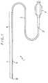
- Fig. 1is a plan view of an embodiment of the vascular catheter of the present invention.
- Fig. 2is a partial longitudinal sectional view of the vascular catheter shown in Fig. 1 which shows the proximal and distal end portions of the catheter.
- Fig. 3is an enlarged longitudinal sectional view of the distal end portion of the vascular catheter shown in Fig. 1 with the radial dimension enlarged at a larger ratio than the axial dimension in order to show the structure clearly.
- the vascular catheter 1 of the present inventioncomprises a catheter body 2 and a hub 11 attached to the proximal end 21 of the catheter body 2 as shown in Figs. 1 and 2.
- the catheter body 2has a lumen 3 formed from the proximal end 21 to the distal end 22.
- a guide wireis passed through the lumen 3.
- the lumen 3serves as the conduit for medicine or other liquid after the catheter is inserted.
- the hub 11serves as the entrance for a guide wire and the inlet for medicine or other liquid into the lumen 3.
- the hub 11is also used as the grip for manipulating the vascular catheter 1.
- the catheter body 2consists of a base or main portion 6 and a tip portion 7.
- the main portion 6has a double-tube structure formed by an inner tube 4 and an outer tube 5 closely fitted over and bonded to an outside surface of the inner tube 4.
- the tip 7 of the catheteris formed by the outer tube 5 alone, that is, by a distal end portion of the outer tube 5 which extends beyond a distal or tip end of the inner tube 4.
- a helical groove 9Ais formed in the inside surface of the distal end portion of the inner tube 4 over an appropriate length from the distal end toward the proximal end. Since the wall thickness of the inner tube 4 is thinner at the bottom of the groove 9A and the width of the groove 9A changes (widens or narrows) when the grooved portion is subjected to an external force thereby decreasing the stress in the wall, the entire grooved portion becomes more flexible.
- the bending force applied to the distal end portion of the catheter when the distal end is passed through bends in blood vesselis dispersed into a larger portion (the grooved portion) and kink at the boundary portion between the comparatively rigid main portion 6 of the double-tube structure and the comparatively flexible tip 7 of the single-tube structure caused by the concentration of stress can be prevented.
- the pitch of the groove 9Abecomes gradually smaller toward the distal end 22.
- the flexibility of the catheter body 2increases gradually toward the distal end 22, and kink at the aforementioned boundary can be prevented with higher reliability.
- the pitchmay be uniform throughout the length of the groove 9A.
- the pitch of the helix of the groove 9Ais preferably smaller than the outer diameter of the inner tube 4, and more preferably within the range of about 2/3 to 1/5 of the outer diameter of the inner tube 4. If the pitch is greater than the outer diameter of the inner tube 4, bending force is not adequately dispersed, and hence kink can occur at the grooved portion against the purpose. If the pitch is smaller than 1/5 of the outer diameter of the inner tube 4, on the other hand, the durability of the distal end portion of the inner tube 4 noticeably decreases and this portion can rupture or break.
- the pitches of groove 9Ais preferably smaller at the distal end portion of the groove and larger at the proximal end portion, and the pitch more preferably becomes gradually smaller toward the distal end. In such a way the flexibility of the portion around the distal end of the inner tube 4 increases more smoothly toward the distal end, which allows this portion of the catheter body 2 to bend in smooth curves and thereby improves the manipulability of the catheter.
- the pitchis preferably within the range of about 0.1 to 0.5 mm for the distal end portion of the groove 9A and about 0.5 to 2.0 mm for the proximal end portion.
- the pitch of the middle portionmay be an intermediate value between the pitches of both end portions or may become gradually smaller from the pitch of the proximal end portion to that of the distal end portion.
- the depth of the groove 9Ais preferably equal to or greater than 50 percent of the wall thickness of the inner tube 4 and more preferably equal to or greater than 80 percent of the same.
- the width of the groove 9Ais preferably about 10 to 100 ⁇ m and more preferably about 10 to 50 ⁇ m taking into consideration the flexibility and the durability, though there is no definite limit.
- the length of the grooved portion of the inner tube 4is preferably within the range of about 5 to 20 times the outer diameter of the inner tube 4 and more preferably within the range of about 10 to 20 times the same.
- the groove 9Amay be formed from the distal end of the inner tube 4 or from a position at an appropriate distance from the distal end of the inner tube 4 as the groove 9A of the embodiment shown in Fig. 3.
- the distance between the distal end of the inner tube 4 and that of the groove 9Ais preferably about 1.0 mm and more preferably 0.5 mm.
- the catheter of this embodimenthas one groove 9A, but two or more grooves may be formed the distal end portion of the inner tube.
- the distal end portion of the inner tube 4 with the groove 9A formed in the inside surfacemay not be bonded to the inside surface of the outer tube 6.
- the distal end portion of the catheter body 2has a higher flexibility.
- the inner diameter of the catheter body 2(diameter of the lumen 3) is substantially uniform throughout the length of the main portion 6.
- the outer diameter of the catheter body 2, on the other hand,is substantially uniform throughout the almost entire length of the main portion 6 except the distal end portion (an appropriate length of portion from the distal end).
- the distal end portion of the main portion 6 and the corresponding distal end portion of the inner tube 4become gradually thinner in wall thickness to their distal ends so that this portion of the catheter body 2 gradually tapers to the distal end of the main portion 6 as shown in Fig.3.
- the distal end of the inner tube 4is formed in a comparatively steep taper 10, and hence the outer diameter and wall thickness of this tapered end become smaller abruptly. It results that the inner diameter of this portion of the outer tube 5 becomes smaller at the large diminishing rate, while the outer diameter decreases gradually as described above.
- the tip portion 7 of the catheter 1is formed by the distal end portion of the outer tube 5 which extends beyond the distal end of the inner tube 4.
- the outer diameter of the tip 7becomes gradually smaller toward the distal as shown in Fig.1, and the wall thickness of the tip 7 also decreases gently toward the distal end, as shown in Fig. 3.
- the vascular catheter of the present inventionhas the following advantages: the rigidity of the catheter body 2 smoothly decreases to the distal end, and hence kink at the boundary between the tip 7 and the main portion 6 (boundary between the single-tube and double-tube structure portions) can be prevented with higher reliability; no step is formed in the outside surface at the boundary between the tip 7 and the main portion 6, and accordingly the catheter can be easily inserted into blood vessel without being caught by the entrance opening of a catheter guide or exerting excessive stimuli on the blood vessel or causing damage to the wall of the blood vessel; and the lumen 3 has a sufficiently large diameter up to the distal end with no narrowing nor step in the inside surface at the boundary between the single- and double-tube
- the vascular catheter of the present inventionis not limited to the structure of the catheter body 2 as described above, particularly as to the shapes of the inner and outer tubes which become smaller at different diminishing rates along the axis of the catheter toward the distal end.
- the outer diameter of the catheter body 2may be uniform or may become gradually smaller toward the distal end at a uniform diminishing rate, throughout the length of the catheter body 2.
- the tapered regionis preferably within the range of about 0.5 to 2.0 mm and more preferably within the range of about 0.5 to 1.0 mm along the axis of the catheter body.
- the dimensions of the catheter body 2there is no particular limitation on the dimensions of the catheter body 2, and the dimensions of the catheter body 2 can be determined so as to be best suited for the purpose of the catheter.
- the entire length of the catheter body 2is preferably about 50 to 200 cm and more preferably about 70 to 150 cm.
- the length of the tip 7is preferably about 5 to 30 cm and more preferably about 10 to 20 cm.
- the outer diameter of the catheter body 2 at the main portion 6is preferably within the range of about 0.6 to 2.0 mm and more preferably within the range of about 0.7 to 1.2 mm.
- the outer diameter of the tip 7is preferably within the range of about 0.3 to 1.0 mm and more preferably within the range of about 0.6 to 0.9 mm.
- the inner diameter of the main portion 6is preferably within the range of about 0.2 to 1.6 mm and more preferably within the range of about 0.3 to 0.9 mm.
- the inner diameter of the tip 7is preferably within the range of about 0.2 to 0.7 mm and more preferably within the range of about 0.3 to 0.6 mm.
- the wall thickness of the outer tube 5 at the main portion 6is preferably within the range of about 0.05 to 0.3 mm and more preferably within the range of about 0.05 to 0.2 mm.
- the wall thickness of the tip 7is preferably about 0.05 to 0.4 mm and more preferably abut 0.07 to 0.3 mm.
- the wall thickness of the inner tube 4is preferably within the range of about 0.05 to 0.5 mm and more preferably within the range of 0.08 to 0.3 mm.
- the vascular catheter 30 shown in Fig. 4has another form of the groove in the inner tube.
- the groove 31is a helical groove whose width becomes gradually larger toward the distal end.
- the width of the groove 31is appropriately determined according to the outer diameter of the inner 4.
- the width of the groove 31is preferably within the range of about 1/2 to 2 times of the outer diameter of the inner tube.
- the width of the groove 31is preferably within the range of about 1.0 to 2.0 mm for the distal end portion of the groove 31 and about 0.1 to 0.5 mm for the proximal end portion. If the width of the groove 31 is within this range, the catheter body 2 has adequate flexibility without breaking of the inner tube 4 during use.
- the pitch of the groove 31is uniform throughout the length of the groove 31.
- the pitch of the groove 31may change along the length of the groove and become gradually smaller toward the distal end as that of the groove 9A of the embodiment shown in Fig. 3.
- the pitchmay also become discontinuously smaller toward the distal end.
- the inner tube 4is preferably formed of a comparatively rigid synthetic resin material.
- the material usable for the inner tube 4includes synthetic resins such as polyolefin (polyethylene, polypropylene, ethylene-vinyl acetate copolymer, etc.), polyamide, polyester (polyethylene-terephthalate, polybutylene-terephthalate, etc.), poly(vinyl chloride), polyurethane, polystyrene resin, fluororesin (polytetrafluoroethylene, etc.) and polyimide, and synthetic resin elastomers such as silicone rubber, polyamide elastomer, polyester elastomer, poly(vinyl chloride) elastomer and polyurethane elastomer. Of these materials, elastomers are preferable, and especially polyamide elastomer and polyester elastomer are preferable.
- the inner tube 4 with appropriate flexural elasticity and high solvent resistanceis prepared.
- the inner tube 4expands or contracts elastically as a spring in the direction of the axis and thereby increases the flexural elasticity of the catheter body 2.
- the catheter body 2with the increased flexural elasticity, can bend more easily in smooth curves along blood vessel, and kink at the boundary between the single- and double-tube portions is prevented with higher reliability.
- polyamide elastomer and polyester elastomerhave comparatively high rigidity at around room temperature giving the catheter body 2 higher pushability and turnability, and become flexible at around body temperature giving catheter body 2 higher flexibility and hence improved pliability and reluctance to kinking after the catheter is inserted in the body of a patient.
- a typical polyamide elastomeris block copolymer of nylon 6, nylon 64, nylon 66, nylon 610, nylon 612, nylon46, nylon 9, nylon 11, nylon 12, N-alkoxymethyl modified nylon, or aliphatic or aromatic polyamide (hexamethylenediamine-isopthalic acid condensation polymer, metaxyloldiamine-adipic acid condensation polymer, etc.) as the hard segment and a polymer such as polyester or polyether as the soft segment.
- polyamide elastomerhere includes a polymer alloy (polymer blend, graft polymer and random polymer) of the above-mentioned polyamide elastomer and one or more soft resins, the above-mentioned polyamide softened with a plasticizer, and a mixture of them.
- a plasticizerone difficult to be extracted with solvents or blood is preferable.
- polyester elastomeris block copolymer of saturated polyester (polyethylene-terephthalate, polybutylene-terephthalate, etc.) and polyester or polyether.
- polyester elastomerhere includes a polymer alloy of the above-mentioned polyester elastomer and one or more soft resins, the above-mentioned polyester softened with a plasticizer, and a mixture of them.
- additivessuch as alloying agent, compatibilizer, hardening agent, softening agent, stabilizer and coloring agent may be added to the above-mentioned elastomers if necessary.
- thermoplastic elastomeris preferable, because forming of the inner tube 4 is easier.
- the inner tube 4is normally formed of a uniform material for the whole, but may be formed of different materials for appropriately determined portions.
- the outer tube 5is preferably formed of a comparatively soft synthetic resin material than the synthetic resin material of the inner tube 4.
- the outer tube 5is preferably more soft than the inner tube 4.
- the resin material usable for the outer tube 5includes synthetic resins such as polyolefin (polyethylene (especially low density polyethylene), polypropylene, ethylene-vinyl acetate copolymer, etc.), polyamide, polyester (polyethylene-terephthalate, polybutylene-terephthalate, etc.), polyurethane, polystyrene resin, fluororesin (polytetrafluoroethylene, etc.) and polyimide, and synthetic resin elastomers such as above-mentioned polyamide elastomer, above-mentioned polyester elastomer, polyurethane elastomer, poly(vinyl chloride) elastomer, polystyrene elastomer, fluoroelastomer, silicone rubber and latex robber.
- synthetic resinssuch as polyolefin (polyethylene (especially low density polyethylene), polypropylene, ethylene-vinyl acetate copolymer, etc.), polyamide
- elastomersare preferable, and especially polyamide elastomer and polyester elastomer are preferable.
- the most preferable elastomeris polyester elastomer.
- thermoplastic elastomeris preferable, because forming of the outer tube 5 is easier.
- the outer tube 5 with softness, appropriate flexural elasticity and high solvent resistanceis prepared.
- the outer tube 5is normally formed of a uniform material for the whole, but may be formed of different materials for appropriately determined portions.
- the rigidity (buckling strength) (ASTM D-790, at 23°c) of the material for the inner tube 4is preferably within the range of 1,500 to 15,000 kg/cm 2 and more preferably 2,000 to 8,000 kg/cm 2 . If the buckling strength of the material is less than 1,500 kg/cm 2 , the catheter body 2 is too flexible to convey pushing force in the direction of the axis and turning force around the axis from the proximal portion to the distal end 22. On the other hand, if the buckling strength is greater than 15,000 kg/cm 2 , the catheter body 2 is too rigid to bend flexibly along the guide wire and exerts excessive force on the wall of blood vessel. Further, the difference between the rigidity of the single-tube and double-tube portions increases and the reluctance to kinking at the boundary portion becomes too low.
- the rigidity (buckling strength) (ASTM D-790, at 23°c) of the material for the outer tube 5is preferably within the range of 5 to 1,500 kg/cm 2 and more preferably 300 to 800 kg/cm 2 . If the buckling strength of the material is less than 5 kg/cm 2 , the catheter body 2 is too flexible to convey pushing force in the direction of the axis and turning force around the axis from the proximal portion to the distal end 22. Further, the difference between the rigidity of the single- and double-tube portions increases and the reluctance to kinking at the boundary becomes too low.
- the difference between the rigidity (buckling strength) (ASTM D-790, at 23 °c) of the materials for the inner and outer tubes 4 and 5is preferably within the range of 100 to 14,000 kg/cm 2 and more preferably 100 to 3,000 kg/cm 2 .
- the entire outside surface of the inner tube 4is in close contact with and bonded to the inside surface of the outer tube 5.
- the methods usable for bonding the inner tube 4 and the outer tube 5are adhering with an adhesive or solvent, welding by heating, and inserting the inner tube 4 into the outer tube 5 swollen with a solvent, for example.
- the inner tube 4is entirely bonded to the outer tube 5 in this embodiment, the distal end portion (grooved portion) of the inner tube 4 may not be bonded to the outer tube 5.
- the method for bonding the inner tube 4 and the outer tube 5 without bonding the distal end portion of the inner tube 4is subjecting the inner and outer tubes 4 and 5 to the bonding process after applying to the distal end portion of the inner tube 4 an appropriate substance (such as silicone, for example silicone oil) which prevents the tubes from bonding together.
- an appropriate substancesuch as silicone, for example silicone oil
- the outside surface of the catheter body 2is preferably coated with a hydrophilic (or water soluble) high-molecular substance.
- the hydrophilic substancebecomes lubricous and decreases the coefficient of friction between the catheter body 2 and blood vessel when it comes into contact with blood or physiologic saline, significantly increasing the easiness of insertion, flexibility to bend along a guide wire or blood vessel, reluctance to kink of the catheter body 2.
- hydrophilic high-molecular substancefor this purpose, the following natural and synthetic high-molecular substances and their derivatives can be used.
- cellulose-derived high-molecular substancehydroxypropyl cellulose, for example
- polyethylene oxide-derived high-molecular substancepolyethylene glycol, for example
- maleic anhydride-derived high-molecular substancemaleic anhydride copolymer such as methyl vinyl ether-maleic anhydride copolymer
- acrylamide-derived high-molecular substancepolyacrylamide, for example
- water-soluble nylonAQ-nylon P-70 from Toray, for example
- Derivatives of the above high-molecule substances usable for this friction reductionare not limited to water-soluble derivatives only and may be insoluble derivatives which have each of the above hydrophilic high-molecule substances as their basic structure and a degree of freedom in molecular chains to contain combined water.
- derivatives usable for the friction reductioninclude ester, salt, amide, anhydride, halide, ether, hydrolysate, acetal, formal, alkylol, quaternary compound, diazo, hydrazide, sulfonated compound, nitro and ion complex obtained by condensation, addition, substitution, oxidation and reduction reaction, compound produced by cross-linking with substances which have more than two reactive functional groups such as diazonium group, azido group, isocyanate group, acid chloride group, acid anhydride group, imino carbonate group, amino group, carboxyl group, epoxy group, hydroxyl group and aldehyde group, vinyl compound, and compound obtained by copolymerization with acrylic acid, methacrylic acid, diene compound and maleic anhydride.
- the coating of such a hydrophilic high-molecular substanceis preferably fixed to the outside surface of the catheter body 2 by bonding the high-molecular substance with the reactive functional group which exists or is introduced in the catheter body 2 or on the surface of the catheter body 2 by covalent bond.
- the reactive functional group which exist or is introduced in the catheter body 2 or on the surface of the catheter body 2may be any group which reacts with the high-molecular substance to bond or cross link, such as diazonium group, azido group, isocyanate group, acid chloride group, acid anhydride group, imino carbonate group, amino group, carboxyl group, epoxy group, hydroxyl group and aldehyde group. Isocyanate group, amino group, epoxy group and hydroxyl group are preferable.
- the average molecular weight of the hydrophilic high-molecular substance used for the friction reductionis preferably within the range of 30,000 to 50,000, though there is no particular limit.
- a hydrophilic high-molecular substance of an average molecular weightwithin this range, a lubricous coating with a high lubricity, a preferable thickness, and a preferable degree of swelling when containing water can be formed.
- the thickness of the lubricous coatingis preferably within the range of 0.1 to 100 ⁇ m and more preferably 1 to to 30 ⁇ m, though there is no particular limit.
- composition of the hydrophilic high-molecular substance used and the method for forming the coatingthose disclosed by Japanese patent application laid open under Provisional Publication No. 106778/1978, U.S. Patent No. 4100309, Japanese patent application laid open under Provisional Publication No. 259269/1985, and Japanese patent application published under Publication No. 33181/1989 can be used.
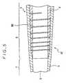
- Fig. 5is an enlarged cross-sectional view of the distal end portion of the vascular catheter of another embodiment of the present invention.
- Fig. 6is a partially broken external view of the distal end portion of the vascular catheter shown in Fig. 5.
- the same parts as those of the catheter shown in Fig. 3are designated by the same numerals and the description of them is omitted.
- the catheter 40has almost the same structure as the catheter 1 shown in Fig. 3. The difference between their structures is that the catheter 40 has a helical slit or slot 9B instead of the helical groove 9A of the catheter 1.
- the helical slot 9Bis formed through the wall of the inner tube 4 from the inside surface to the outside surface. Since the width of the slot 9B can change more easily than that of the groove 9A, the flexibility of the portion provided with the helical slot 9B is greater than that of the portion provided with the helical groove 9A as shown in Fig. 3, though the strength becomes smaller.
- the width of the helical slot 9B of the catheter 40 of this embodimentis appropriately determined by taking into account the outer diameter of the inner tubes 4. It is preferably within the range of about 1/5 to 2 times of the outer diameter of the inner tube 4. For a preferred embodiment, the width of the slot 9B is preferably within the range of about 0.1 to 2.0 mm. If the width of the slot 9B is within this range, the catheter has adequate flexibility without occurrence of breaking of the inner tube 4 during use.
- the pitch of the slot 9Bbecomes gradually smaller toward the distal end as shown in Figs. 5 and 6.
- the pitch of the slot 9Bmay become discontinuously smaller toward the distal end.
- the slotmay also have the shape as that of the slot 51 of the catheter 50 shown in Fig.7.
- the width of the slot 51is greater at the distal end portion of the slot 51 and smaller at the proximal end portion.
- the width of the helical slot 51 of the catheter 50is determined by taking into account the diameter of the inner tube 4 and other factors.
- the width of the slotis preferably within the range of about 1/2 to 2 times of the outer diameter of the inner tube 4.
- the width of the slot 51is preferably within the range of about 1.0 to 2.0 mm for the distal end portion and within the range of about 0.1 to 0.5 mm for the the proximal end portion. If the width of the slot is within this range, the catheter has adequate flexibility and there is no occurrence of breaking of the inner tube 4 during use.
- the pitch of the slot 51is uniform throughout the length of the slot.
- the pitch of the slot 51may become gradually smaller toward the distal end as that of the slot 41 of the embodiment shown in Fig. 6 or may become discontinuously smaller toward the distal end.
- the catheters 40 and 50has one slot 41 or 51, but two or more slot may be formed the distal end portion of the inner tube.
- Fig. 8is an enlarged partially-broken external view of the distal end portion of another embodiment of the vascular catheter of present invention.
- the same parts as those of the catheter shown in Fig. 3are designated by the same numerals and the description of them is omitted.
- the vascular catheter 70has almost the same structure as the catheter 1 shown in Fig. 3. The difference between their structures is that the catheter 70 has a number of microholes 71 in the distal end portion of the inner tube 4 instead of the helical groove 9A of the catheter 1 shown in Fig. 3.
- the diameter of the microholesis determined taking into account the number of microholes 71, the outer diameter of the inner tube 4 and other factors.
- the diameter of the microholes 71is preferably within the range of about 0.1 to 0.4 mm and more preferably within the range of about 0.2 to 0.3 mm.
- the diameter of the microholes 71is preferably within the range of about 1/10 to 1/3 of the outer diameter of the inner tube 4.
- the distance between the microholes 71is preferably about 0.1 to 0.5 mm when the microholes 71 are formed in a uniform density.
- the length from the distal end of the inner tube 4 of the region where the microholes 71 are formedis determined taking into account the length of the catheter, and preferably within the range of about 5 to 20 mm and more preferably within the range of about 10 to 20 mm.
- the density of the microholes 71is preferably greater at the distal end portion than at the proximal end portion of the region provided with the microholes 71, and more preferably the density of the microholes 71 becomes gradually greater toward the distal end as shown in Fig. 8.
- the distance between the microholes 71is preferably within about 0.1 to 0.2 mm for the distal end portion and about 0.3 to 0.5 mm for the proximal end portion.
- the densitymay increase discontinuously or gradually toward the distal end.
- the diameter of the microholes 71may be changed so that the diameter of the microholes at the distal end portion is greater than that of the microholes at the proximal end portion.
- the shape of the microholes 71need not be a circle and may be an ellipse (ellipse elongated in the direction of the axis, for example) or a polygon (rectangle or pentagon, for example).
- each microholeis preferably within the range of about 0.007 to 0.13 mm 2 and the distance between microholes is preferably within the range of about 0.1 to 0.5 mm.
- the distal end portion of the inner tube 4may be made of a material more elastic than that of the other portion of the inner tube 4 in order to increase the flexibility of that portion of the inner tube 4.
- the groove, slot, slit, microholes in the inner tube 4may be filled with the resin material of the outer tube 5, though it is preferable that they are substantially left unfilled, more preferable that they make spaces.
- the groove, slot, slit or microhole of the inner tubeforms a space in the inner tube as showm in Figures.
- a tubing for the inner tube 4was formed of a polyamide elastomer which is copolymer of polytetramethyleneglycol and nylon 12 (Product Name Pebax 7033, Toray Corporation, Buckling strength: 4390 kg/cm 2 (ASTM D-790 at 23 °c)).
- the outer tube 5was formed of a polyester elastomer which is copolymer of polytetramethyleneoxide and polybutyleneterephthalate (Product Name Hytrel 4077, Toray corporation, Buckling strength: 720 kg/cm 2 (ASTM D-790 at 23 °c)).
- One end portion of the tubing for the inner tube 4was heated and drawn into a tapered shape with the outer diameter becoming gradually smaller toward the end.
- the groove 9Awas 0.35 mm in width and 0.06 mm in depth on average.
- the beginning end of the groove 9Awas 1.0 mm from the distal end (the end of the tapered portion) of the inner tube 4.
- the length of the grooved portionwas 10 mm.
- the pitch of the helixwas 0.30 mm at the most distal side and 0.60 mm at the most proximal side and became gradually smaller toward the distal end.
- the inner tube 4 prepared as abovewas inserted into the outer tube 5, and both tubes were bonded together by heating.
- a catheter body 2 of the structure as shown in Fig. 3was made.
- a hub 11was attached to the proximal end 21 of the catheter body 2, and the first example of the vascular catheter of the present invention was made.
- the dimensions of the catheter body 2were as follows.
- Another catheter body of the vascular catheter of the present inventionwas made in the same manner as example 1, except that a helical slot as shown in Fig. 5 instead of the helical groove was formed. Finally, a hub 11 was attached to the proximal end 21 of the catheter body 2, and the second example of the vascular catheter of the present invention was made.
- the helical slotwas 0.35 mm in width on the average.
- the beginning end of the slotwas 1.0 mm from the distal end of the inner tube 4.
- the length along the axis of the portion provided with the helical slotwas 10 mm.
- the pitch of the helixwas 0.30 mm at the most distal side and 0.60 mm at the most proximal side and became gradually smaller toward the distal end.
- a vascular catheter for comparisonwas made in the same manner as in example 1, except that no groove was formed in the inner tube.
- vascular catheters of examples 1 and 2 and the comparison examplewere subjected to the following bending test to examine the reluctance to kink at the boundary between the single-tube and double-tube structures.
- the boundary portion of the catheter body of each catheterwas pressed around cylinders of different outer diameters in water at 37 °c to bend at the curvature of the each cylinder, and the diameter of the cylinder when folds occurred in the catheter body was measured (the measurement was repeated 5 times).
- the vascular catheter of this inventioncan bend more easily along a guide wire and blood vessels than conventional catheters because of the structure of the catheter body having the proximal main portion made up of double tubes and the distal tip made up of a single tube and the higher flexibility of the distal end portion of the inner tube increased by a helical groove, a helical slot, a helical slit or microholes.
- the vascular catheter of this inventionhence has a higher reluctance to kicking, exerts smaller stimuli on blood vessels, causes less damage to the wall of blood vessels, improved manipulability, and higher safety than conventional catheters.
Landscapes
- Health & Medical Sciences (AREA)
- Life Sciences & Earth Sciences (AREA)
- Biophysics (AREA)
- Pulmonology (AREA)
- Engineering & Computer Science (AREA)
- Anesthesiology (AREA)
- Biomedical Technology (AREA)
- Heart & Thoracic Surgery (AREA)
- Hematology (AREA)
- Animal Behavior & Ethology (AREA)
- General Health & Medical Sciences (AREA)
- Public Health (AREA)
- Veterinary Medicine (AREA)
- Media Introduction/Drainage Providing Device (AREA)
Description
- The present invention relates to a vascular catheterused for intravascular surgical operation, highly localizedinjection of medicine such as anticancer drugs, andangiography.
- Medical treatment using vascular catheters isdeveloping to smaller and smaller blood vessels as from theheart to the brain. Lesions of the brain blood vessels areaneurysm, arteriovenous malformation (AVM) and duralarteriovenous fistula (DAVF), for example. Demand for avascular catheter for treating or examining such lesions ofblood vessels is more and more increasing.
- A vascular catheter for this purpose must be insertedto the intended part of a blood vessel being passed incomplicatedly bent or branched blood vessels.
- For an intravascular surgical operation calledemboluation technique conducted for treating lesions in thebrain blood vessels such as aneurysm and arteriovenousmalformation, for example, the distal end of a small-diametervascular catheter is inserted to or near thelesions in the brain. Then, a liquid embolizing materialsuch as cyanoacrylate or dimethylsulfoxide solution ofethylene-vinyl alcohol copolymer, a granular embolizingmaterial such as granules of poly(vinyl alcohol) or aexpanding member such as coil is injected from the distalend of the catheter.
- For such a small-diameter vascular catheter, highmanipulability to insert it easily and quickly up to atarget lesion passing in complicatedly bent or branchedsmall blood vessel is required in addition to the chemicaland biological safety required for common vascularcatheters.
- To have high manipulability, a small-diameter vascularcatheter must have the following four properties.
- The first property is that the catheter can convey thepushing force in the direction of the axis added to theproximal end portion by the operator up to the distal end orhas so called pushability.
- The second property is that the catheter can convey theturning force around the axis added to the proximal endportion up to the distal end or has so called turnability.
- The third property is that the catheter can be advancedin blood vessels along the guide wire inserted beforehandeasily and without causing damage to the wall of the bloodvessels or has so called pliability.
- The fourth property is that the catheter does not kinkat bents (curves and crooks) in blood vessels after theguide wire is removed or has reluctance to kinking.
- A vascular catheter having a catheter body of thedouble-tube structure made up of a comparatively rigid innertube and a comparatively soft and flexible outer tubecovering the outside surface of the inner tube and havingthe distal end portion extending beyond the distal end ofthe inner tube and forming the tip of the catheter body wasdeveloped and currently used.
- In more detail, U.S. Patent 4,385,635 discloses a vascular catheter in which the inner tube is formed ofpolyamide and the outer tube is formed of polyurethane andthe distal end portion is tapered so that the inner diameterbecomes gradually smaller to the distal end. This catheterhas a problem that it kinks easily at the boundary betweenthe two-tube portion and the single tube portion because ofthe abrupt change of the rigidity at the boundary.
- Japanese utility model application published underPublication No. 17082/1987 discloses a vascular catheterwhich uses the outer tube formed of silicone rubber and theinner tube formed of a hard synthetic resin selected fromamong polyethylene, polypropylene, fluororesin and hardvinyl chloride. In this catheter, a step of the height equalto the wall thickness of the inner tube is formed in thelumen at the boundary between the two-tube portion and thesingle tube portion. Because of the step, this catheterkinks easily at the boundary and hence has small reluctanceto kinking.
- Further, a vascular catheter recently put to practicaluse which uses the inner tube formed of polypropylene andthe outer tube formed of ethylene-vinyl acetate copolymerhas also the same problem of small reluctance to kinking.
- The object of this invention is to provide a vascularcatheter of a double-tube structure which has improvedeasiness of insertion, flexibility to bend along a guidewire or blood vessel, reluctance to kink, and manipulabilityand can be used for small blood vessels.
- The vascular catheter of the present invention is a vascular catheter comprising a flexible slendercatheter body which is made up of an comparatively rigid inner tube formed of asynthetic resin and acomparatively soft and flexibleouter tube formed of a syntheticresin covering the outside surface of the inner tube and hasa lumen. Said catheter body has a main portion and a tipportion, the main portion of the catheter body being made up ofthe inner and outer tubes. The tip of the catheter body ismade up of the portion of said outer tube extending from thedistal end of the inner tube. At least one helical groove,helical slot, helical slit or a number of microholes is formed inthe inside surface of the distal end portion of the inner tube.
- The invention will now be further explained on hand of the followingnon limitative examples illustrated by the appended drawings on which:
- FIG. 1 is a plan view of an embodiment of the vascularcatheter of an embodiment of the present invention.
- Fig. 2 is a longitudinal sectional view of the vascularcatheter shown in Fig. 1.
- Fig. 3 is an enlarged longitudinal sectional view ofthe distal end portion of the vascular catheter shown inFig. 1.
- Fig. 4 is an enlarged longitudinal sectional view ofthe distal end portion of the vascular catheter of anotherembodiment of the present invention.
- Fig. 5 is an enlarged longitudinal sectional view ofthe distal end portion of the vascular catheter of anotherembodiment of the present invention.
- Fig. 6 is a partially broken external view of thedistal end portion of the catheter shown in Fig. 5.
- Fig. 7 is a partially broken external view of thedistal end portion of the vascular catheter of another embodiment of the present invention.
- Fig. 8 is a partially broken external view of thedistal end portion of the vascular catheter of anotherembodiment of the present invention.
- Fig. 1 is a plan view of an embodiment of the vascularcatheter of the present invention. Fig. 2 is a partiallongitudinal sectional view of the vascular catheter shownin Fig. 1 which shows the proximal and distal end portionsof the catheter. Fig. 3 is an enlarged longitudinalsectional view of the distal end portion of the vascularcatheter shown in Fig. 1 with the radial dimension enlargedat a larger ratio than the axial dimension in order to showthe structure clearly.
- The vascular catheter 1 of the present inventioncomprises a
catheter body 2 and ahub 11 attached to theproximal end 21 of thecatheter body 2 as shown in Figs. 1and 2. - The
catheter body 2 has alumen 3 formed from theproximal end 21 to thedistal end 22. When the vascularcatheter 1 is inserted into the blood vessel of a patient, a guide wire is passed through thelumen 3. Thelumen 3 servesas the conduit for medicine or other liquid after thecatheter is inserted. Thehub 11 serves as the entrance fora guide wire and the inlet for medicine or other liquid intothelumen 3. Thehub 11 is also used as the grip formanipulating the vascular catheter 1. - The
catheter body 2 consists of a base ormain portion 6 and atip portion 7. Themain portion 6 has a double-tubestructure formed by aninner tube 4 and anouter tube 5closely fitted over and bonded to an outside surface of theinner tube 4. Thetip 7 of the catheter is formed by theouter tube 5 alone, that is, by a distal end portion of theouter tube 5 which extends beyond a distal or tip end of theinner tube 4. - In the embodiment shown in Fig. 3, a
helical groove 9Ais formed in the inside surface of the distal end portion oftheinner tube 4 over an appropriate length from the distalend toward the proximal end. Since the wall thickness of theinner tube 4 is thinner at the bottom of thegroove 9A andthe width of thegroove 9A changes (widens or narrows) whenthe grooved portion is subjected to an external forcethereby decreasing the stress in the wall, the entiregrooved portion becomes more flexible. Therefore, thebending force applied to the distal end portion of thecatheter when the distal end is passed through bends inblood vessel is dispersed into a larger portion (the groovedportion) and kink at the boundary portion between thecomparatively rigidmain portion 6 of the double-tubestructure and the comparativelyflexible tip 7 of thesingle-tube structure caused by the concentration of stress can be prevented. - In the embodiment shown in Fig. 3, the pitch of the
groove 9A becomes gradually smaller toward thedistal end 22. By thus forming thegroove 9A, the flexibility of thecatheter body 2 increases gradually toward thedistal end 22, and kink at the aforementioned boundary can be preventedwith higher reliability. The pitch may be uniform throughoutthe length of thegroove 9A. - The pitch of the helix of the
groove 9A is preferablysmaller than the outer diameter of theinner tube 4, andmore preferably within the range of about 2/3 to 1/5 of theouter diameter of theinner tube 4. If the pitch is greaterthan the outer diameter of theinner tube 4, bending forceis not adequately dispersed, and hence kink can occur at thegrooved portion against the purpose. If the pitch is smallerthan 1/5 of the outer diameter of theinner tube 4, on theother hand, the durability of the distal end portion of theinner tube 4 noticeably decreases and this portion canrupture or break. - The pitches of
groove 9A is preferably smallerat the distal end portion of the groove and larger at theproximal end portion, and the pitch more preferably becomesgradually smaller toward the distal end. In such a waythe flexibility of the portion around thedistal end of theinner tube 4 increases more smoothlytoward the distal end, which allows this portion of thecatheter body 2 to bend in smooth curves and therebyimproves the manipulability of the catheter. - The pitch is preferably within the range of about 0.1to 0.5 mm for the distal end portion of the
groove 9A and about 0.5 to 2.0 mm for the proximal end portion. The pitchof the middle portion may be an intermediate value betweenthe pitches of both end portions or may become graduallysmaller from the pitch of the proximal end portion to thatof the distal end portion. - The depth of the
groove 9A is preferably equal to orgreater than 50 percent of the wall thickness of theinnertube 4 and more preferably equal to or greater than 80percent of the same. The width of thegroove 9A ispreferably about 10 to 100 µm and more preferably about 10to 50 µm taking into consideration the flexibility and thedurability, though there is no definite limit. - The length of the grooved portion of the
inner tube 4 ispreferably within the range of about 5 to 20 times the outerdiameter of theinner tube 4 and more preferably within therange of about 10 to 20 times the same. - The
groove 9A may be formed from the distal end of theinner tube 4 or from a position at an appropriate distancefrom the distal end of theinner tube 4 as thegroove 9A ofthe embodiment shown in Fig. 3. The distance between thedistal end of theinner tube 4 and that of thegroove 9A ispreferably about 1.0 mm and more preferably 0.5 mm. Thecatheter of this embodiment has onegroove 9A, but two ormore grooves may be formed the distal end portion of theinner tube. - The distal end portion of the
inner tube 4 with thegroove 9A formed in the inside surface may not be bonded tothe inside surface of theouter tube 6. When the distal endportion of theinner tube 4 is not bonded to the to theouter tube 6, the distal end portion of thecatheter body 2 has a higher flexibility. - In this embodiment, the inner diameter of the catheterbody 2 (diameter of the lumen 3) is substantially uniformthroughout the length of the
main portion 6. The outerdiameter of thecatheter body 2, on the other hand, issubstantially uniform throughout the almost entire length ofthemain portion 6 except the distal end portion (anappropriate length of portion from the distal end). - The distal end portion of the
main portion 6 and thecorresponding distal end portion of theinner tube 4 becomegradually thinner in wall thickness to their distal ends sothat this portion of thecatheter body 2 gradually tapers tothe distal end of themain portion 6 as shown in Fig.3. - Further, in this embodiment, the distal end of the
inner tube 4 is formed in a comparativelysteep taper 10,and hence the outer diameter and wall thickness of thistapered end become smaller abruptly. It results that theinner diameter of this portion of theouter tube 5 becomessmaller at the large diminishing rate, while the outerdiameter decreases gradually as described above. - The
tip portion 7 of the catheter 1 is formed by thedistal end portion of theouter tube 5 which extends beyondthe distal end of theinner tube 4. The outer diameter ofthetip 7 becomes gradually smaller toward the distal asshown in Fig.1, and the wall thickness of thetip 7 alsodecreases gently toward the distal end, as shown in Fig. 3. - By thus gently tapering the outside surface of thedistal end portion of the main portion 6 and tip 7 towardthe distal end along the axis and moreover decreasing thewall thickness of these portions of the inner and outer tubes 4 and 5 so that the diameter of the lumen 3 issubstantially uniform or decreases at a smaller diminishingrate to the distal end of the catheter, the vascularcatheter of the present invention has the followingadvantages: the rigidity of the catheter body 2 smoothlydecreases to the distal end, and hence kink at the boundarybetween the tip 7 and the main portion 6 (boundary betweenthe single-tube and double-tube structure portions) can beprevented with higher reliability; no step is formed in theoutside surface at the boundary between the tip 7 and themain portion 6, and accordingly the catheter can be easilyinserted into blood vessel without being caught by theentrance opening of a catheter guide or exerting excessivestimuli on the blood vessel or causing damage to the wall ofthe blood vessel; and the lumen 3 has a sufficiently largediameter up to the distal end with no narrowing nor step inthe inside surface at the boundary between the single- anddouble-tube portions, and hence passing of a guide wirethrough the lumen 3 becomes easier and kink at the boundaryis prevented.
- The vascular catheter of the present invention is notlimited to the structure of the
catheter body 2 as describedabove, particularly as to the shapes of the inner and outertubes which become smaller at different diminishing ratesalong the axis of the catheter toward the distal end. Forexample, the outer diameter of thecatheter body 2 may beuniform or may become gradually smaller toward the distalend at a uniform diminishing rate, throughout the length ofthecatheter body 2. - When the
taper 10 is formed at the distal end of theinner tube 4 as shown in Fig. 3, the tapered region ispreferably within the range of about 0.5 to 2.0 mm and morepreferably within the range of about 0.5 to 1.0 mm along theaxis of the catheter body. - There is no particular limitation on the dimensions ofthe
catheter body 2, and the dimensions of thecatheter body 2 can be determined so as to be best suited for the purposeof the catheter. - For the vascular catheter used for cerebral bloodvessel, for example, the entire length of the
catheter body 2 is preferably about 50 to 200 cm and more preferably about70 to 150 cm. The length of thetip 7 is preferably about 5to 30 cm and more preferably about 10 to 20 cm. - The outer diameter of the
catheter body 2 at themainportion 6 is preferably within the range of about 0.6 to 2.0mm and more preferably within the range of about 0.7 to 1.2mm. The outer diameter of thetip 7 is preferably within therange of about 0.3 to 1.0 mm and more preferably within therange of about 0.6 to 0.9 mm. - The inner diameter of the
main portion 6 is preferablywithin the range of about 0.2 to 1.6 mm and more preferablywithin the range of about 0.3 to 0.9 mm. The inner diameterof thetip 7 is preferably within the range of about 0.2 to0.7 mm and more preferably within the range of about 0.3 to0.6 mm. - The wall thickness of the
outer tube 5 at themainportion 6 is preferably within the range of about 0.05 to0.3 mm and more preferably within the range of about 0.05 to0.2 mm. The wall thickness of thetip 7 is preferably about0.05 to 0.4 mm and more preferably abut 0.07 to 0.3 mm. The wall thickness of theinner tube 4 is preferably within therange of about 0.05 to 0.5 mm and more preferably within therange of 0.08 to 0.3 mm. - The
vascular catheter 30 shown in Fig. 4 has anotherform of the groove in the inner tube. Thegroove 31 is ahelical groove whose width becomes gradually larger towardthe distal end. By forming such ahelical groove 31, theflexibility of the portion around the distal end of theinner tube 4 increases more smoothly toward the distal end,which allows this portion of thecatheter body 2 to bend insmooth curves and improves the manipulability of thecatheter. - The width of the
groove 31 is appropriately determinedaccording to the outer diameter of the inner 4. In relationto the outer diameter of theinner tube 4, the width of thegroove 31 is preferably within the range of about 1/2 to 2times of the outer diameter of the inner tube. For apreferred embodiment, the width of thegroove 31 ispreferably within the range of about 1.0 to 2.0 mm for thedistal end portion of thegroove 31 and about 0.1 to 0.5 mmfor the proximal end portion. If the width of thegroove 31is within this range, thecatheter body 2 has adequateflexibility without breaking of theinner tube 4 during use. - The pitch of the
groove 31 is uniform throughout thelength of thegroove 31. The pitch of thegroove 31 maychange along the length of the groove and become graduallysmaller toward the distal end as that of thegroove 9A ofthe embodiment shown in Fig. 3. The pitch may also becomediscontinuously smaller toward the distal end. - The
inner tube 4 is preferably formed of a comparatively rigid synthetic resin material. The materialusable for theinner tube 4 includes synthetic resins suchas polyolefin (polyethylene, polypropylene, ethylene-vinylacetate copolymer, etc.), polyamide, polyester(polyethylene-terephthalate, polybutylene-terephthalate,etc.), poly(vinyl chloride), polyurethane, polystyreneresin, fluororesin (polytetrafluoroethylene, etc.) andpolyimide, and synthetic resin elastomers such as siliconerubber, polyamide elastomer, polyester elastomer, poly(vinylchloride) elastomer and polyurethane elastomer. Of thesematerials, elastomers are preferable, and especiallypolyamide elastomer and polyester elastomer are preferable. - By using at least one of these materials, the
innertube 4 with appropriate flexural elasticity and high solventresistance is prepared. - When an elastomer is used, the
inner tube 4 expands orcontracts elastically as a spring in the direction of theaxis and thereby increases the flexural elasticity of thecatheter body 2. Thecatheter body 2, with the increasedflexural elasticity, can bend more easily in smooth curvesalong blood vessel, and kink at the boundary between thesingle- and double-tube portions is prevented with higherreliability. - Further, polyamide elastomer and polyester elastomerhave comparatively high rigidity at around room temperaturegiving the
catheter body 2 higher pushability andturnability, and become flexible at around body temperaturegivingcatheter body 2 higher flexibility and hence improvedpliability and reluctance to kinking after the catheter isinserted in the body of a patient. - A typical polyamide elastomer is block copolymer of
nylon 6, nylon 64, nylon 66, nylon 610, nylon 612, nylon46,nylon 9,nylon 11, nylon 12, N-alkoxymethyl modified nylon,or aliphatic or aromatic polyamide (hexamethylenediamine-isopthalicacid condensation polymer, metaxyloldiamine-adipicacid condensation polymer, etc.) as the hard segmentand a polymer such as polyester or polyether as the softsegment. Further, polyamide elastomer here includes apolymer alloy (polymer blend, graft polymer and randompolymer) of the above-mentioned polyamide elastomer and oneor more soft resins, the above-mentioned polyamide softenedwith a plasticizer, and a mixture of them. For theplasticizer, one difficult to be extracted with solvents orblood is preferable. - A typical polyester elastomer is block copolymer ofsaturated polyester (polyethylene-terephthalate,polybutylene-terephthalate, etc.) and polyester orpolyether. Further, polyester elastomer here includes apolymer alloy of the above-mentioned polyester elastomer andone or more soft resins, the above-mentioned polyestersoftened with a plasticizer, and a mixture of them.
- Various additives such as alloying agent,compatibilizer, hardening agent, softening agent, stabilizerand coloring agent may be added to the above-mentionedelastomers if necessary.
- A thermoplastic elastomer is preferable, becauseforming of the
inner tube 4 is easier. - The
inner tube 4 is normally formed of a uniformmaterial for the whole, but may be formed of differentmaterials for appropriately determined portions. - The
outer tube 5 is preferably formed of acomparatively soft synthetic resin material than thesynthetic resin material of theinner tube 4. Theoutertube 5 is preferably more soft than theinner tube 4. - The resin material usable for the
outer tube 5 includessynthetic resins such as polyolefin (polyethylene(especially low density polyethylene), polypropylene,ethylene-vinyl acetate copolymer, etc.), polyamide,polyester (polyethylene-terephthalate, polybutylene-terephthalate,etc.), polyurethane, polystyrene resin,fluororesin (polytetrafluoroethylene, etc.) and polyimide,and synthetic resin elastomers such as above-mentionedpolyamide elastomer, above-mentioned polyester elastomer,polyurethane elastomer, poly(vinyl chloride) elastomer,polystyrene elastomer, fluoroelastomer, silicone rubber andlatex robber. - In these materials, elastomers are preferable, andespecially polyamide elastomer and polyester elastomer arepreferable. The most preferable elastomer is polyesterelastomer.
- A thermoplastic elastomer is preferable, becauseforming of the
outer tube 5 is easier. - By using at least one of these materials, the
outertube 5 with softness, appropriate flexural elasticity andhigh solvent resistance is prepared. - The
outer tube 5 is normally formed of a uniformmaterial for the whole, but may be formed of differentmaterials for appropriately determined portions. - The rigidity (buckling strength) (ASTM D-790, at 23°c)of the material for the
inner tube 4 is preferably within the range of 1,500 to 15,000 kg/cm2 and more preferably2,000 to 8,000 kg/cm2. If the buckling strength of thematerial is less than 1,500 kg/cm2, thecatheter body 2 istoo flexible to convey pushing force in the direction of theaxis and turning force around the axis from the proximalportion to thedistal end 22. On the other hand, if thebuckling strength is greater than 15,000 kg/cm2, thecatheter body 2 is too rigid to bend flexibly along theguide wire and exerts excessive force on the wall of bloodvessel. Further, the difference between the rigidity of thesingle-tube and double-tube portions increases and thereluctance to kinking at the boundary portion becomes toolow. - The rigidity (buckling strength) (ASTM D-790, at 23°c)of the material for the
outer tube 5 is preferably withinthe range of 5 to 1,500 kg/cm2 and more preferably 300 to800 kg/cm2. If the buckling strength of the material is lessthan 5 kg/cm2, thecatheter body 2 is too flexible to conveypushing force in the direction of the axis and turning forcearound the axis from the proximal portion to thedistal end 22. Further, the difference between the rigidity of thesingle- and double-tube portions increases and thereluctance to kinking at the boundary becomes too low. - The difference between the rigidity (buckling strength)(ASTM D-790, at 23 °c) of the materials for the inner and
outer tubes - In the catheter of this embodiment, substantaillythe entire outside surface of the
inner tube 4 is in closecontact with and bonded to the inside surface of theouter tube 5. The methods usable for bonding theinner tube 4 andtheouter tube 5 are adhering with an adhesive or solvent,welding by heating, and inserting theinner tube 4 into theouter tube 5 swollen with a solvent, for example.Although theinner tube 4 is entirely bonded to theoutertube 5 in this embodiment, the distal end portion (groovedportion) of theinner tube 4 may not be bonded to theoutertube 5. The method for bonding theinner tube 4 and theouter tube 5 without bonding the distal end portion of theinner tube 4 is subjecting the inner andouter tubes inner tube 4 an appropriate substance (suchas silicone, for example silicone oil) which prevents thetubes from bonding together. - The outside surface of the
catheter body 2 ispreferably coated with a hydrophilic (or water soluble)high-molecular substance. The hydrophilic substance becomeslubricous and decreases the coefficient of friction betweenthecatheter body 2 and blood vessel when it comes intocontact with blood or physiologic saline, significantlyincreasing the easiness of insertion, flexibility to bendalong a guide wire or blood vessel, reluctance to kink ofthecatheter body 2. - For the hydrophilic high-molecular substance for thispurpose, the following natural and synthetic high-molecularsubstances and their derivatives can be used.
- 1. Starch related substance
Example: Carboxymethyl starch, Dialdehyde starch - 2. Cellulose related substance
Example: CMC (Carboxymethyl cellulose), MC (Methylcellulose), HEC (hydroxyethyl cellulose), HPC(hydroxypropyl cellulose) - 3. Tannin and lignin and related substance
Example: Tannin, Lignin - 4. Polysaccharide related substance
Example: Alginic acid, Gum arabic, Gua gum, Tragacanth gum - 5. Protein
Example: Gelatin, Casein, Glue, Collagen - 1. PVA related substance
Example: Poly(vinyl alcohol) - 2. Polyethylene oxide related substance
Example: Polyethylene oxide, Polyethylene glycol - 3. Acrylic acid related substance
Example: Polyacrylic acid soda - 4. Maleic anhydride related substance
Example: Methyl vinyl ether-maleic anhydride copolymer - 5. Phthalic acid related substance
Example: Polyhydroxyethyl-phthalic acid ester - 6. Water-soluble polyester
Example: Polydimethylol-propionic acid ester - 7. Ketone aldehyde resin
Example: Methylisopropylketone-formaldehyde resin - 8. Acrylamide
Example: Polyacrylamide - 9. PVP
Example: Poly(vinyl pyrrolidone) - 10. Polyamine
Example: Polyethyleneimine - 11. Polyelectrolyte
Example: Polystyrene sulfonate - 12. Others
Example: Water-soluble nylon - Of the above substances, cellulose-derived high-molecularsubstance (hydroxypropyl cellulose, for example),polyethylene oxide-derived high-molecular substance(polyethylene glycol, for example), maleic anhydride-derivedhigh-molecular substance (maleic anhydride copolymer such asmethyl vinyl ether-maleic anhydride copolymer), acrylamide-derivedhigh-molecular substance (polyacrylamide, forexample), water-soluble nylon (AQ-nylon P-70 from Toray, forexample) are preferable, because a small coefficient offriction is obtained stably.
- Derivatives of the above high-molecule substancesusable for this friction reduction are not limited to water-solublederivatives only and may be insoluble derivativeswhich have each of the above hydrophilic high-moleculesubstances as their basic structure and a degree of freedomin molecular chains to contain combined water.
- Therefore, derivatives usable for the frictionreduction include ester, salt, amide, anhydride, halide,ether, hydrolysate, acetal, formal, alkylol, quaternarycompound, diazo, hydrazide, sulfonated compound, nitro andion complex obtained by condensation, addition,substitution, oxidation and reduction reaction, compoundproduced by cross-linking with substances which have more than two reactive functional groups such as diazonium group,azido group, isocyanate group, acid chloride group, acidanhydride group, imino carbonate group, amino group,carboxyl group, epoxy group, hydroxyl group and aldehydegroup, vinyl compound, and compound obtained bycopolymerization with acrylic acid, methacrylic acid, dienecompound and maleic anhydride.
- The coating of such a hydrophilic high-molecularsubstance is preferably fixed to the outside surface of the
catheter body 2 by bonding the high-molecular substance withthe reactive functional group which exists or is introducedin thecatheter body 2 or on the surface of thecatheterbody 2 by covalent bond. By thus fixing the coating of ahydrophilic high-molecular substance to the outside surfaceof thecatheter body 2, a durable lubricous surface isobtained. - The reactive functional group which exist or isintroduced in the
catheter body 2 or on the surface of thecatheter body 2 may be any group which reacts with the high-molecularsubstance to bond or cross link, such as diazoniumgroup, azido group, isocyanate group, acid chloride group,acid anhydride group, imino carbonate group, amino group,carboxyl group, epoxy group, hydroxyl group and aldehydegroup. Isocyanate group, amino group, epoxy group andhydroxyl group are preferable. - The average molecular weight of the hydrophilic high-molecularsubstance used for the friction reduction ispreferably within the range of 30,000 to 50,000, thoughthere is no particular limit. By using a hydrophilic high-molecularsubstance of an average molecular weight within this range, a lubricous coating with a high lubricity, apreferable thickness, and a preferable degree of swellingwhen containing water can be formed.
- The thickness of the lubricous coating is preferablywithin the range of 0.1 to 100 µm and more preferably 1 toto 30 µm, though there is no particular limit.
- For the composition of the hydrophilic high-molecularsubstance used and the method for forming the coating, thosedisclosed by Japanese patent application laid open underProvisional Publication No. 106778/1978, U.S. Patent No.4100309, Japanese patent application laid open underProvisional Publication No. 259269/1985, and Japanese patentapplication published under Publication No. 33181/1989 canbe used.
- Next, the vascular catheter of the embodiment shown inFig. 5 is described.
- Fig. 5 is an enlarged cross-sectional view of thedistal end portion of the vascular catheter of anotherembodiment of the present invention. Fig. 6 is a partiallybroken external view of the distal end portion of thevascular catheter shown in Fig. 5. The same parts as thoseof the catheter shown in Fig. 3 are designated by the samenumerals and the description of them is omitted.
- The
catheter 40 has almost the same structure as thecatheter 1 shown in Fig. 3. The difference between theirstructures is that thecatheter 40 has a helical slit orslot 9B instead of thehelical groove 9A of the catheter 1.Thehelical slot 9B is formed through the wall of theinnertube 4 from the inside surface to the outside surface. Sincethe width of theslot 9B can change more easily than that of thegroove 9A, the flexibility of the portion provided withthehelical slot 9B is greater than that of the portionprovided with thehelical groove 9A as shown in Fig. 3,though the strength becomes smaller. - The width of the
helical slot 9B of thecatheter 40 ofthis embodiment is appropriately determined by taking intoaccount the outer diameter of theinner tubes 4. It ispreferably within the range of about 1/5 to 2 times of theouter diameter of theinner tube 4. For a preferredembodiment, the width of theslot 9B is preferably withinthe range of about 0.1 to 2.0 mm. If the width of theslot 9B is within this range, the catheter has adequateflexibility without occurrence of breaking of theinner tube 4 during use. - The pitch of the
slot 9B becomes gradually smallertoward the distal end as shown in Figs. 5 and 6. The pitchof theslot 9B may become discontinuously smaller toward thedistal end. - The slot may also have the shape as that of the
slot 51of thecatheter 50 shown in Fig.7. In this embodiment, thewidth of theslot 51 is greater at the distal end portion oftheslot 51 and smaller at the proximal end portion. Byforming the slot in this shape, the flexibility of theportion provided with the slot increases gradually towardthe distal end, and hence the portion around the distal endof theinner tube 4 bend more easily in smooth curves toimprove the manipulability of the catheter. - The width of the
helical slot 51 of thecatheter 50 isdetermined by taking into account the diameter of theinnertube 4 and other factors. The width of the slot is preferably within the range of about 1/2 to 2 times of theouter diameter of theinner tube 4. For a preferredembodiment, the width of theslot 51 is preferably withinthe range of about 1.0 to 2.0 mm for the distal end portionand within the range of about 0.1 to 0.5 mm for the theproximal end portion. If the width of the slot is withinthis range, the catheter has adequate flexibility and thereis no occurrence of breaking of theinner tube 4 during use. - The pitch of the
slot 51 is uniform throughout thelength of the slot. The pitch of theslot 51 may becomegradually smaller toward the distal end as that of the slot41 of the embodiment shown in Fig. 6 or may becomediscontinuously smaller toward the distal end. Thecatheters slot 41 or 51, but two or more slot may beformed the distal end portion of the inner tube. - Next, the vascular catheter of the embodiment shown inFig. 8 is described.
- Fig. 8 is an enlarged partially-broken external viewof the distal end portion of another embodiment of thevascular catheter of present invention. The same parts asthose of the catheter shown in Fig. 3 are designated by thesame numerals and the description of them is omitted.
- The
vascular catheter 70 has almost the same structureas the catheter 1 shown in Fig. 3. The difference betweentheir structures is that thecatheter 70 has a number ofmicroholes 71 in the distal end portion of theinner tube 4instead of thehelical groove 9A of the catheter 1 shown inFig. 3. - The diameter of the microholes is determined takinginto account the number of
microholes 71, the outer diameterof theinner tube 4 and other factors. The diameter of themicroholes 71 is preferably within the range of about 0.1 to0.4 mm and more preferably within the range of about 0.2 to0.3 mm. Relatively to the outer diameter of theinner tube 4, the diameter of themicroholes 71 is preferably withinthe range of about 1/10 to 1/3 of the outer diameter of theinner tube 4. - The distance between the
microholes 71 is preferablyabout 0.1 to 0.5 mm when themicroholes 71 are formed in auniform density. - The length from the distal end of the
inner tube 4 ofthe region where themicroholes 71 are formed is determinedtaking into account the length of the catheter, andpreferably within the range of about 5 to 20 mm and morepreferably within the range of about 10 to 20 mm. - The density of the
microholes 71 is preferably greaterat the distal end portion than at the proximal end portionof the region provided with themicroholes 71, and morepreferably the density of themicroholes 71 becomesgradually greater toward the distal end as shown in Fig. 8. - When forming the
microholes 71 at different densitiesalong the axis, the distance between themicroholes 71 ispreferably within about 0.1 to 0.2 mm for the distal endportion and about 0.3 to 0.5 mm for the proximal end portion.The density may increase discontinuously or gradually towardthe distal end. - Further, instead of changing the density of the
microholes 71, the diameter of themicroholes 71 may bechanged so that the diameter of the microholes at the distalend portion is greater than that of the microholes at theproximal end portion. - The shape of the
microholes 71 need not be a circle andmay be an ellipse (ellipse elongated in the direction of theaxis, for example) or a polygon (rectangle or pentagon,for example). - The area of each microhole is preferably within therange of about 0.007 to 0.13 mm2 and the distance betweenmicroholes is preferably within the range of about 0.1 to0.5 mm.
- Although the present invention is described above with reference to the embodiments shown in the drawings, thepresent invention is not limited to the structures of thoseembodiments and includes various modifications andvariations. For example, the distal end portion of the
innertube 4 may be made of a material more elastic than that ofthe other portion of theinner tube 4 in order to increasethe flexibility of that portion of theinner tube 4. - Further, the groove, slot, slit, microholes in the
inner tube 4 may be filled with the resin material of theouter tube 5, though it is preferable that they aresubstantially left unfilled, more preferable that they makespaces. The groove, slot, slit or microhole of the innertube forms a space in the inner tube as showm in Figures. - Next, examples of the vascular catheter of presentinvention are described below in detail.
- A tubing for the
inner tube 4 was formed of a polyamideelastomer which is copolymer of polytetramethyleneglycol andnylon 12 (Product Name Pebax 7033, Toray Corporation,Buckling strength: 4390 kg/cm2 (ASTM D-790 at 23 °c)). Theouter tube 5 was formed of a polyester elastomer which iscopolymer of polytetramethyleneoxide and polybutyleneterephthalate(Product Name Hytrel 4077, Toray corporation,Buckling strength: 720 kg/cm2 (ASTM D-790 at 23 °c)). - One end portion of the tubing for the
inner tube 4 washeated and drawn into a tapered shape with the outerdiameter becoming gradually smaller toward the end. - The end portion of this tapered portion was put over ascrew having a projecting helical rib and heated from the outside, and the screw was pulled off. Thus a
helical groove 9A extending in the direction of the axis was formed in theinside surface of theinner tube 4. - The
groove 9A was 0.35 mm in width and 0.06 mm in depthon average. The beginning end of thegroove 9A was 1.0 mmfrom the distal end (the end of the tapered portion) of theinner tube 4. The length of the grooved portion was 10 mm.The pitch of the helix was 0.30 mm at the most distal sideand 0.60 mm at the most proximal side and became graduallysmaller toward the distal end. - The
inner tube 4 prepared as above was inserted intotheouter tube 5, and both tubes were bonded together byheating. Thus acatheter body 2 of the structure as shown inFig. 3 was made. - Finally, a
hub 11 was attached to theproximal end 21of thecatheter body 2, and the first example of thevascular catheter of the present invention was made. - The dimensions of the
catheter body 2 were as follows. - Overall length of the catheter body: 150 cm
- Length of the main portion: 130 cm
- Length of the tip portion: 20 cm
- Outer diameter of the catheter body:
- From the proximal end to 120 cm: 1.1 mm
- From 120 cm to 130 cm: Gradually decreasesfrom 1.1 mm to 1.0 mm.
- From 130 cm to the tip end: Graduallydecreases from 1.0 to 0.75 mm.
- Inner diameter of the catheter body:
- Main portion: 0.65 mm
- Tip portion: Gradually decreasesfrom 0.65 mm to 0.55 mm
- Wall thickness of the inner tube:
- From the proximal end to 120 cm: 0.14 mm
- From 120 cm to 129.9 cm: Gradually decreases from0.14 mm to 0.08 mm.
- From 129.9 cm to the tip end: Decreases from0.08 to 0 mm.
- Another catheter body of the vascular catheter of thepresent invention was made in the same manner as example 1,except that a helical slot as shown in Fig. 5 instead of thehelical groove was formed. Finally, a
hub 11 was attached totheproximal end 21 of thecatheter body 2, and the secondexample of the vascular catheter of the present inventionwas made. - The helical slot was 0.35 mm in width on the average.The beginning end of the slot was 1.0 mm from the distal endof the
inner tube 4. The length along the axis of theportion provided with the helical slot was 10 mm. The pitchof the helix was 0.30 mm at the most distal side and 0.60 mmat the most proximal side and became gradually smallertoward the distal end. - A vascular catheter for comparison was made in the samemanner as in example 1, except that no groove was formed inthe inner tube.
- The vascular catheters of examples 1 and 2 and thecomparison example were subjected to the following bendingtest to examine the reluctance to kink at the boundarybetween the single-tube and double-tube structures.
- The boundary portion of the catheter body of eachcatheter was pressed around cylinders of different outer diameters in water at 37 °c to bend at the curvature of theeach cylinder, and the diameter of the cylinder when foldsoccurred in the catheter body was measured (the measurementwas repeated 5 times).
- The test result is shown in Table 1.
Folds Occurred in Catheter Body Example 1 5.0 mm Example 2 4.5 mm Com. Ex. 7.0 mm - It is known from Table 1 that the vascular catheters ofthe present invention of examples 1 and 2 endure bending ofgreater curvature than the catheter of the comparisonexample and have a higher reluctance to kink.
- As described above, the vascular catheter of thisinvention can bend more easily along a guide wire and bloodvessels than conventional catheters because of the structureof the catheter body having the proximal main portion madeup of double tubes and the distal tip made up of a singletube and the higher flexibility of the distal end portion ofthe inner tube increased by a helical groove, a helicalslot, a helical slit or microholes.The vascular catheter of this invention hence has a higherreluctance to kicking, exerts smaller stimuli on bloodvessels, causes less damage to the wall of blood vessels, improved manipulability, and higher safety than conventionalcatheters.
Claims (14)
- A vascular catheter (1,30,40,50) comprising a flexible slendercatheter body (2) which is made up of an comparatively rigid inner tube (4) formed of asynthetic resin and a comparatively soft and flexible outer tube (5) formed of a syntheticresin covering the outside surface of the inner tube (4) and hasa main portion (6), tip portion (7) and a lumen (3),said main portion (6) of said catheter body being made up ofsaid inner tube and said outer tube,said tip (7) of said catheter body being made up of theportion of said outer tube (5) which extends from the distal endof said inner tube (4), characterized in thatat least one helical groove (9A,31) helical slot (9B,51) or helical slitis formed in the inside surface of the distal end portion of theinner tube (4)extending from or from near the distal end to an appropriateposition in the direction of the axis so as to increase flexibilityof the distal end portion of the inner tube (4).
- The vascular catheter of claim 1 wherein said outertube (5) is formed of a synthetic resin softer than thesynthetic resin of which said inner tube (4) is formed.
- The vascular catheter of claim 1 or 2 wherein saidsynthetic resin for both or either one of said inner andouter tubes is a synthetic resin elastomer.
- The vascular catheter of any preceding claim wherein the pitch of said helical groove, helical slot or helical slit becomesgradually smaller toward the distal end.
- The vascular catheter of any preceding claim wherein the width ofsaid helical groove, helical slot or helical slit becomesgradually greater toward the distal end.
- The vascular catheter of any preceding claim wherein said catheteris a brain blood vessel catheter.
- The vascular catheter of any preceding claim wherein said groove,slot or slit forms a space in said inner tube.
- A vascular catheter comprising a flexible slender catheterbody which is made up of a comparatively rigid inner tube (4) formedof a synthetic resin and a comparatively soft and flexible outer tubeformed of a synthetic resin covering the outside surface of the innertube (4) and has a main portion (6), tip portion (7) and a lumen (3),said main portion (6) of said catheter body being made up ofsaid inner tube and said outer tube,said tip (7) of said catheter body being made up of theportion of said outer tube (5) which extends from the distal end of saidinner tube (34), characterized in thata number of microholes are provided only through the wall ofthe inner tube in the distal end portion of the inner tube so as toincrease flexibility of the distal end portion of the inner tube (4).
- The vascular catheter of claim 8 wherein saidsynthetic resin for both or either one of said inner andouter tubes is a synthetic resin elastomer.
- The vascular catheter of claim 8 or 9 wherein thedensity of the microholes is greater at the distal end sidethan at the proximal end side.
- The vascular catheter of claim 8 or 9 wherein the areaof the microholes is greater at the distal end side than atthe proximal end side.
- The vascular catheter of any of claims 8 to 11 wherein said catheteris a brain blood vessel catheter.
- The vascular catheter of any of claims 8 to 12 wherein saidmicroholes form spaces in said inner tube.
- The vascular catheter of any of claims 8 to 13 whereinsaid outer tube is formed of a synthetic resinsofter than the synthetic resin of which said inner tubeis formed.
Applications Claiming Priority (3)
| Application Number | Priority Date | Filing Date | Title |
|---|---|---|---|
| JP15979093AJP3383009B2 (en) | 1993-06-29 | 1993-06-29 | Vascular catheter |
| JP15979093 | 1993-06-29 | ||
| JP159790/93 | 1993-06-29 |
Publications (2)
| Publication Number | Publication Date |
|---|---|
| EP0631791A1 EP0631791A1 (en) | 1995-01-04 |
| EP0631791B1true EP0631791B1 (en) | 2000-08-16 |
Family
ID=15701326
Family Applications (1)
| Application Number | Title | Priority Date | Filing Date |
|---|---|---|---|
| EP94110039AExpired - LifetimeEP0631791B1 (en) | 1993-06-29 | 1994-06-28 | Vascular catheter |
Country Status (4)
| Country | Link |
|---|---|
| US (1) | US5531719A (en) |
| EP (1) | EP0631791B1 (en) |
| JP (1) | JP3383009B2 (en) |
| DE (1) | DE69425531T2 (en) |
Cited By (2)
| Publication number | Priority date | Publication date | Assignee | Title |
|---|---|---|---|---|
| US7488338B2 (en) | 2001-12-27 | 2009-02-10 | Boston Scientific Scimed, Inc. | Catheter having an improved torque transmitting shaft |
| US7670302B2 (en) | 2001-12-18 | 2010-03-02 | Boston Scientific Scimed, Inc. | Super elastic guidewire with shape retention tip |
Families Citing this family (116)
| Publication number | Priority date | Publication date | Assignee | Title |
|---|---|---|---|---|
| JP3970341B2 (en)* | 1994-06-20 | 2007-09-05 | テルモ株式会社 | Vascular catheter |
| US5599326A (en)* | 1994-12-20 | 1997-02-04 | Target Therapeutics, Inc. | Catheter with multi-layer section |
| EP0729766A1 (en)* | 1995-03-03 | 1996-09-04 | Cordis Europa N.V. | Microcatheter |
| ES2236792T3 (en)* | 1995-03-27 | 2005-07-16 | Sdgi Holdings, Inc. | IMPLANTS OF SPINAL FUSION AND INSTRUMENTS FOR INSERTION AND REVIEW. |
| US5843050A (en) | 1995-11-13 | 1998-12-01 | Micro Therapeutics, Inc. | Microcatheter |
| US20030069522A1 (en) | 1995-12-07 | 2003-04-10 | Jacobsen Stephen J. | Slotted medical device |
| JP3529537B2 (en)* | 1996-03-25 | 2004-05-24 | テルモ株式会社 | Electrode catheter |
| US5836926A (en)* | 1996-05-13 | 1998-11-17 | Schneider (Usa) Inc | Intravascular catheter |
| US6042578A (en)* | 1996-05-13 | 2000-03-28 | Schneider (Usa) Inc. | Catheter reinforcing braids |
| US6440088B1 (en)* | 1996-05-24 | 2002-08-27 | Precision Vascular Systems, Inc. | Hybrid catheter guide wire apparatus and method |
| US6622367B1 (en)* | 1998-02-03 | 2003-09-23 | Salient Interventional Systems, Inc. | Intravascular device and method of manufacture and use |
| IE980241A1 (en)* | 1998-04-02 | 1999-10-20 | Salviac Ltd | Delivery catheter with split sheath |
| US6045547A (en)* | 1998-06-15 | 2000-04-04 | Scimed Life Systems, Inc. | Semi-continuous co-extruded catheter shaft |
| JP3637216B2 (en)* | 1998-10-09 | 2005-04-13 | ペンタックス株式会社 | Endoscopic treatment tool |
| KR20010080519A (en)* | 1998-12-16 | 2001-08-22 | 쿡 인코포레이티드 | Finishing technique for a guiding catheter |
| US6413228B1 (en) | 1998-12-28 | 2002-07-02 | Pro Duct Health, Inc. | Devices, methods and systems for collecting material from a breast duct |
| JP2000279507A (en)* | 1999-03-30 | 2000-10-10 | Nippon Zeon Co Ltd | Balloon catheter with low temperature blow molded balloon |
| WO2000066211A1 (en)* | 1999-04-30 | 2000-11-09 | Usaminanotechnology, Inc. | Catheter and guide wire |
| JP4666702B2 (en)* | 1999-10-06 | 2011-04-06 | 株式会社塚田メディカル・リサーチ | Intermittent self urinary catheter |
| JP2001137348A (en)* | 1999-11-12 | 2001-05-22 | Goodman Co Ltd | Catheter |
| JP3909991B2 (en)* | 1999-11-26 | 2007-04-25 | テルモ株式会社 | catheter |
| US6475184B1 (en) | 2000-06-14 | 2002-11-05 | Scimed Life Systems, Inc. | Catheter shaft |
| AU2001271517A1 (en)* | 2000-06-29 | 2002-01-14 | Minitube Of America, Inc. | Coextruded plastic catheter |
| US6500130B2 (en) | 2000-12-21 | 2002-12-31 | Scimed Life Systems, Inc. | Steerable guidewire |
| US7245959B1 (en)* | 2001-03-02 | 2007-07-17 | Scimed Life Systems, Inc. | Imaging catheter for use inside a guiding catheter |
| DE10131152B4 (en)* | 2001-04-30 | 2004-05-27 | Nutricia Healthcare S.A. | Medical balloon button system |
| DE20110121U1 (en)* | 2001-06-19 | 2002-12-05 | B. Braun Melsungen Ag, 34212 Melsungen | catheter |
| US20030009208A1 (en) | 2001-07-05 | 2003-01-09 | Precision Vascular Systems, Inc. | Torqueable soft tip medical device and method of usage |
| US6652508B2 (en) | 2001-11-09 | 2003-11-25 | Scimed Life Systems, Inc. | Intravascular microcatheter having hypotube proximal shaft with transition |
| US7163524B2 (en)* | 2002-02-27 | 2007-01-16 | Terumo Kabushiki Kaisha | Catheter |
| US20040147903A1 (en)* | 2002-04-05 | 2004-07-29 | Lucas Latini | Microcatheter having tip relief region |
| JP3813112B2 (en)* | 2002-06-26 | 2006-08-23 | テルモ株式会社 | Catheter and medical tubing |
| DE60334122D1 (en)* | 2002-07-25 | 2010-10-21 | Boston Scient Ltd | MEDICAL DEVICE FOR NAVIGATING THROUGH ANATOMY |
| US7914467B2 (en)* | 2002-07-25 | 2011-03-29 | Boston Scientific Scimed, Inc. | Tubular member having tapered transition for use in a medical device |
| US8337968B2 (en) | 2002-09-11 | 2012-12-25 | Boston Scientific Scimed, Inc. | Radiation sterilized medical devices comprising radiation sensitive polymers |
| US8377035B2 (en) | 2003-01-17 | 2013-02-19 | Boston Scientific Scimed, Inc. | Unbalanced reinforcement members for medical device |
| US7169118B2 (en) | 2003-02-26 | 2007-01-30 | Scimed Life Systems, Inc. | Elongate medical device with distal cap |
| ES2325398T3 (en) | 2003-02-26 | 2009-09-03 | Boston Scientific Limited | BALL CATETER. |
| US7001369B2 (en) | 2003-03-27 | 2006-02-21 | Scimed Life Systems, Inc. | Medical device |
| CA2536368A1 (en)* | 2003-08-19 | 2005-03-03 | Nmt Medical, Inc. | Expandable sheath tubing |
| US8388630B2 (en)* | 2003-09-18 | 2013-03-05 | Boston Scientific Scimed, Inc. | Medical retrieval devices and methods |
| US7575568B2 (en)* | 2003-12-10 | 2009-08-18 | Boston Scientific Scimed, Inc. | Catheter distal tip |
| US7824345B2 (en) | 2003-12-22 | 2010-11-02 | Boston Scientific Scimed, Inc. | Medical device with push force limiter |
| US7468051B2 (en)* | 2004-03-02 | 2008-12-23 | Boston Scientific Scimed, Inc. | Occlusion balloon catheter with external inflation lumen |
| US7666217B2 (en)* | 2004-10-29 | 2010-02-23 | Boston Scientific Scimed, Inc. | Implantable medical endoprosthesis delivery systems and related components |
| US7989042B2 (en)* | 2004-11-24 | 2011-08-02 | Boston Scientific Scimed, Inc. | Medical devices with highly flexible coated hypotube |
| WO2006085498A1 (en)* | 2005-02-10 | 2006-08-17 | Kaneka Corporation | Medical catheter tube and method of producing the same |
| JP5112288B2 (en)* | 2005-03-10 | 2013-01-09 | メデイカル コンポーネンツ,インコーポレーテツド | Catheter with large diameter proximal end |
| US9480589B2 (en)* | 2005-05-13 | 2016-11-01 | Boston Scientific Scimed, Inc. | Endoprosthesis delivery system |
| US7850623B2 (en) | 2005-10-27 | 2010-12-14 | Boston Scientific Scimed, Inc. | Elongate medical device with continuous reinforcement member |
| US7718106B2 (en)* | 2006-05-30 | 2010-05-18 | Boston Scientific Scimed, Inc. | Medical devices and related systems and methods |
| US8551020B2 (en) | 2006-09-13 | 2013-10-08 | Boston Scientific Scimed, Inc. | Crossing guidewire |
| US8556914B2 (en) | 2006-12-15 | 2013-10-15 | Boston Scientific Scimed, Inc. | Medical device including structure for crossing an occlusion in a vessel |
| US8562557B2 (en)* | 2007-05-25 | 2013-10-22 | Medical Components, Inc. | Small diameter dual lumen catheter |
| EP2000159A1 (en)* | 2007-06-07 | 2008-12-10 | NewCorTec S.p.A. | A duct for a ventricular assistance device |
| EP2164548A4 (en) | 2007-06-26 | 2011-12-07 | Avalon Lab Llc | Coaxial venal cannula |
| US8409114B2 (en) | 2007-08-02 | 2013-04-02 | Boston Scientific Scimed, Inc. | Composite elongate medical device including distal tubular member |
| US8105246B2 (en) | 2007-08-03 | 2012-01-31 | Boston Scientific Scimed, Inc. | Elongate medical device having enhanced torque and methods thereof |
| US8821477B2 (en) | 2007-08-06 | 2014-09-02 | Boston Scientific Scimed, Inc. | Alternative micromachined structures |
| US9808595B2 (en) | 2007-08-07 | 2017-11-07 | Boston Scientific Scimed, Inc | Microfabricated catheter with improved bonding structure |
| WO2009035745A1 (en)* | 2007-09-14 | 2009-03-19 | Avalon Laboratories, Llc | Cannula reinforcing band and method |
| US7841994B2 (en) | 2007-11-02 | 2010-11-30 | Boston Scientific Scimed, Inc. | Medical device for crossing an occlusion in a vessel |
| WO2009079506A1 (en)* | 2007-12-17 | 2009-06-25 | Boston Scientific Scimed, Inc. | Retrieval device |
| US20090209941A1 (en)* | 2008-02-19 | 2009-08-20 | William Cook Europe, Aps | Implant deployment catheter |
| JP5188242B2 (en)* | 2008-03-31 | 2013-04-24 | テルモ株式会社 | In vivo insertion probe |
| US8376961B2 (en) | 2008-04-07 | 2013-02-19 | Boston Scientific Scimed, Inc. | Micromachined composite guidewire structure with anisotropic bending properties |
| US8968355B2 (en)* | 2008-08-04 | 2015-03-03 | Covidien Lp | Articulating surgical device |
| WO2010017537A2 (en)* | 2008-08-08 | 2010-02-11 | Incept, Llc | Apparatus and methods for accessing and removing material from body lumens |
| US20100049167A1 (en)* | 2008-08-20 | 2010-02-25 | Cook Incorporated | Introducer sheath having reinforced distal taper |
| US8535243B2 (en) | 2008-09-10 | 2013-09-17 | Boston Scientific Scimed, Inc. | Medical devices and tapered tubular members for use in medical devices |
| US10363389B2 (en) | 2009-04-03 | 2019-07-30 | Scientia Vascular, Llc | Micro-fabricated guidewire devices having varying diameters |
| US11406791B2 (en) | 2009-04-03 | 2022-08-09 | Scientia Vascular, Inc. | Micro-fabricated guidewire devices having varying diameters |
| US12220538B2 (en) | 2008-12-08 | 2025-02-11 | Scientia Vascular, Inc. | Micro-fabricated intravascular devices having varying diameters |
| WO2010077692A2 (en) | 2008-12-08 | 2010-07-08 | Scientia Vascular Llc | Micro-cutting machine for forming cuts in products |
| US8795254B2 (en) | 2008-12-10 | 2014-08-05 | Boston Scientific Scimed, Inc. | Medical devices with a slotted tubular member having improved stress distribution |
| US9616195B2 (en) | 2009-04-03 | 2017-04-11 | Scientia Vascular, Llc | Micro-fabricated catheter devices having varying diameters |
| AU2010232448B2 (en)* | 2009-04-03 | 2013-11-14 | Scientia Vascular, Inc. | Micro-fabricated catheter and guidewire devices |
| US9950137B2 (en) | 2009-04-03 | 2018-04-24 | Scientia Vascular, Llc | Micro-fabricated guidewire devices formed with hybrid materials |
| US8137293B2 (en) | 2009-11-17 | 2012-03-20 | Boston Scientific Scimed, Inc. | Guidewires including a porous nickel-titanium alloy |
| US20110184509A1 (en)* | 2010-01-27 | 2011-07-28 | Abbott Laboratories | Dual sheath assembly and method of use |
| US20110208292A1 (en)* | 2010-02-19 | 2011-08-25 | Abbott Laboratories | Hinged sheath assembly and method of use |
| JP5399301B2 (en)* | 2010-03-12 | 2014-01-29 | テルモ株式会社 | catheter |
| US8551021B2 (en) | 2010-03-31 | 2013-10-08 | Boston Scientific Scimed, Inc. | Guidewire with an improved flexural rigidity profile |
| US8795202B2 (en) | 2011-02-04 | 2014-08-05 | Boston Scientific Scimed, Inc. | Guidewires and methods for making and using the same |
| US9072874B2 (en) | 2011-05-13 | 2015-07-07 | Boston Scientific Scimed, Inc. | Medical devices with a heat transfer region and a heat sink region and methods for manufacturing medical devices |
| US8945025B2 (en)* | 2011-12-30 | 2015-02-03 | St. Jude Medical, Atrial Fibrillation Division, Inc. | Catheter with atraumatic tip |
| US9901706B2 (en) | 2014-04-11 | 2018-02-27 | Boston Scientific Scimed, Inc. | Catheters and catheter shafts |
| US10207080B2 (en)* | 2015-04-20 | 2019-02-19 | Je Bum Lee | Catheter apparatus for cranial cavity |
| KR101846071B1 (en)* | 2015-06-05 | 2018-04-05 | 이제범 | catheter apparatus for cranial cavity |
| JP7082052B2 (en) | 2015-09-03 | 2022-06-07 | ネプチューン メディカル インク. | A device for advancing the endoscope in the small intestine |
| US10118012B2 (en) | 2015-10-30 | 2018-11-06 | Acclarent, Inc. | System and method for anesthetizing eustachian tube |
| US11351048B2 (en) | 2015-11-16 | 2022-06-07 | Boston Scientific Scimed, Inc. | Stent delivery systems with a reinforced deployment sheath |
| JP6419099B2 (en)* | 2016-01-20 | 2018-11-07 | 日本ライフライン株式会社 | Cautery needle device, induction cautery treatment system and chemical cautery treatment system |
| US11052228B2 (en) | 2016-07-18 | 2021-07-06 | Scientia Vascular, Llc | Guidewire devices having shapeable tips and bypass cuts |
| US11207502B2 (en) | 2016-07-18 | 2021-12-28 | Scientia Vascular, Llc | Guidewire devices having shapeable tips and bypass cuts |
| US10646689B2 (en) | 2016-07-29 | 2020-05-12 | Cephea Valve Technologies, Inc. | Mechanical interlock for catheters |
| EP3500151A4 (en) | 2016-08-18 | 2020-03-25 | Neptune Medical Inc. | DEVICE AND METHOD FOR IMPROVED VISUALIZATION OF THE SMALL BOWEL |
| US10821268B2 (en) | 2016-09-14 | 2020-11-03 | Scientia Vascular, Llc | Integrated coil vascular devices |
| US11452541B2 (en) | 2016-12-22 | 2022-09-27 | Scientia Vascular, Inc. | Intravascular device having a selectively deflectable tip |
| ES2966345T3 (en) | 2017-05-26 | 2024-04-22 | Scientia Vascular Inc | Microfabricated medical device with a non-helical cutting arrangement |
| JP7379321B2 (en) | 2017-07-20 | 2023-11-14 | ネプチューン メディカル インク. | Dynamically rigid overtube |
| CN111465420B (en)* | 2017-12-15 | 2023-04-18 | 佩尔福兹有限公司 | Improved catheter and apparatus and system incorporating same |
| US11305095B2 (en) | 2018-02-22 | 2022-04-19 | Scientia Vascular, Llc | Microfabricated catheter having an intermediate preferred bending section |
| US12059128B2 (en) | 2018-05-31 | 2024-08-13 | Neptune Medical Inc. | Device and method for enhanced visualization of the small intestine |
| JP6906883B2 (en)* | 2018-06-04 | 2021-07-21 | 日本ライフライン株式会社 | Balloon catheter |
| CN112714658A (en) | 2018-07-19 | 2021-04-27 | 海王星医疗公司 | Dynamic rigidized composite medical structure |
| US12011555B2 (en) | 2019-01-15 | 2024-06-18 | Scientia Vascular, Inc. | Guidewire with core centering mechanism |
| US11793392B2 (en) | 2019-04-17 | 2023-10-24 | Neptune Medical Inc. | External working channels |
| WO2020214221A1 (en) | 2019-04-17 | 2020-10-22 | Neptune Medical Inc. | Dynamically rigidizing composite medical structures |
| US12343485B2 (en) | 2020-01-23 | 2025-07-01 | Scientia Vascular, Inc. | High torque guidewire device |
| US12178975B2 (en) | 2020-01-23 | 2024-12-31 | Scientia Vascular, Inc. | Guidewire having enlarged, micro-fabricated distal section |
| CA3178444A1 (en) | 2020-03-30 | 2021-10-07 | Neptune Medical Inc. | Layered walls for rigidizing devices |
| US12296112B2 (en) | 2020-10-05 | 2025-05-13 | Scientia Vascular, Inc. | Microfabricated catheter devices with high axial strength |
| KR20230133374A (en) | 2021-01-29 | 2023-09-19 | 넵튠 메디컬 인코포레이티드 | Device and method for preventing inadvertent movement of a dynamic stiffening device |
| KR20250003955A (en) | 2022-04-27 | 2025-01-07 | 넵튠 메디컬 인코포레이티드 | Sanitary outer covering for endoscope |
| US12330292B2 (en) | 2023-09-28 | 2025-06-17 | Neptune Medical Inc. | Telescoping robot |
Family Cites Families (27)
| Publication number | Priority date | Publication date | Assignee | Title |
|---|---|---|---|---|
| US3498286A (en)* | 1966-09-21 | 1970-03-03 | American Optical Corp | Catheters |
| JPS506192A (en)* | 1973-05-18 | 1975-01-22 | ||
| US4100309A (en)* | 1977-08-08 | 1978-07-11 | Biosearch Medical Products, Inc. | Coated substrate having a low coefficient of friction hydrophilic coating and a method of making the same |
| DE2946385A1 (en)* | 1979-11-16 | 1981-05-21 | Siemens AG, 1000 Berlin und 8000 München | PLASTIC HOSE |
| US4385635A (en)* | 1980-04-25 | 1983-05-31 | Ruiz Oscar F | Angiographic catheter with soft tip end |
| US4430083A (en)* | 1981-03-06 | 1984-02-07 | American Hospital Supply Corporation | Infusion catheter |
| JPS5886129A (en)* | 1981-11-17 | 1983-05-23 | 旭光学工業株式会社 | Flexible tube of endoscope and production thereof |
| US4464176A (en)* | 1982-06-04 | 1984-08-07 | Mallinckrodt, Inc. | Blood vessel catheter for medicine delivery and method of manufacture |
| US4616652A (en)* | 1983-10-19 | 1986-10-14 | Advanced Cardiovascular Systems, Inc. | Dilatation catheter positioning apparatus |
| US4801297A (en)* | 1984-06-01 | 1989-01-31 | Edward Weck Incorporated | Catheter having slit tip |
| AU566085B2 (en)* | 1984-06-04 | 1987-10-08 | Terumo Kabushiki Kaisha | Medical instrument with surface treatment |
| JPS6217082A (en)* | 1985-07-15 | 1987-01-26 | 株式会社 応用企画 | Manufacture of porous sintered body |
| US4739768B2 (en)* | 1986-06-02 | 1995-10-24 | Target Therapeutics Inc | Catheter for guide-wire tracking |
| US4840622A (en)* | 1987-10-06 | 1989-06-20 | Menlo Care, Inc. | Kink resistant catheter |
| US4998923A (en)* | 1988-08-11 | 1991-03-12 | Advanced Cardiovascular Systems, Inc. | Steerable dilatation catheter |
| US4985022A (en)* | 1988-11-23 | 1991-01-15 | Med Institute, Inc. | Catheter having durable and flexible segments |
| US4955862A (en)* | 1989-05-22 | 1990-09-11 | Target Therapeutics, Inc. | Catheter and catheter/guide wire device |
| DE3935256C1 (en)* | 1989-10-23 | 1991-01-03 | Bauerfeind, Peter, Dr., 8264 Waldkraiburg, De | |
| JP2528011B2 (en)* | 1989-12-20 | 1996-08-28 | テルモ株式会社 | Catheter |
| US5147315A (en)* | 1990-04-06 | 1992-09-15 | C. R. Bard, Inc. | Access catheter and system for use in the female reproductive system |
| US5180376A (en)* | 1990-05-01 | 1993-01-19 | Cathco, Inc. | Non-buckling thin-walled sheath for the percutaneous insertion of intraluminal catheters |
| US5244619A (en)* | 1991-05-03 | 1993-09-14 | Burnham Warren R | Method of making catheter with irregular inner and/or outer surfaces to reduce travelling friction |
| US5380304A (en)* | 1991-08-07 | 1995-01-10 | Cook Incorporated | Flexible, kink-resistant, introducer sheath and method of manufacture |
| US5275152A (en)* | 1992-07-27 | 1994-01-04 | Welch Allyn, Inc. | Insertion tube terminator |
| JP3310031B2 (en)* | 1992-10-23 | 2002-07-29 | テルモ株式会社 | Catheter tube |
| US5357979A (en)* | 1992-12-01 | 1994-10-25 | Intelliwire, Inc. | Flexible elongate device having a distal extremity with current controlled adjustable stiffness and adjustable bend location and method |
| JP3122850U (en) | 2006-03-06 | 2006-06-29 | 呉明徳 | Packing tool for band |
- 1993
- 1993-06-29JPJP15979093Apatent/JP3383009B2/ennot_activeExpired - Fee Related
- 1994
- 1994-06-28USUS08/266,553patent/US5531719A/ennot_activeExpired - Lifetime
- 1994-06-28EPEP94110039Apatent/EP0631791B1/ennot_activeExpired - Lifetime
- 1994-06-28DEDE69425531Tpatent/DE69425531T2/ennot_activeExpired - Fee Related
Cited By (3)
| Publication number | Priority date | Publication date | Assignee | Title |
|---|---|---|---|---|
| US7670302B2 (en) | 2001-12-18 | 2010-03-02 | Boston Scientific Scimed, Inc. | Super elastic guidewire with shape retention tip |
| US7488338B2 (en) | 2001-12-27 | 2009-02-10 | Boston Scientific Scimed, Inc. | Catheter having an improved torque transmitting shaft |
| US8231647B2 (en) | 2001-12-27 | 2012-07-31 | Boston Scientific Scimed, Inc. | Catheter having an improved torque transmitting shaft |
Also Published As
| Publication number | Publication date |
|---|---|
| EP0631791A1 (en) | 1995-01-04 |
| JP3383009B2 (en) | 2003-03-04 |
| US5531719A (en) | 1996-07-02 |
| DE69425531T2 (en) | 2001-01-11 |
| JPH078560A (en) | 1995-01-13 |
| DE69425531D1 (en) | 2000-09-21 |
Similar Documents
| Publication | Publication Date | Title |
|---|---|---|
| EP0631791B1 (en) | Vascular catheter | |
| US6451005B1 (en) | Catheter | |
| JP3659664B2 (en) | Medical tube | |
| US5336205A (en) | Flow directed catheter | |
| US6171296B1 (en) | Flow directed catheter | |
| US5782809A (en) | Vascular catheter | |
| CA1191064A (en) | Catheter with selectively rigidified portion | |
| CA2127257C (en) | Lubricious catheters | |
| JPH07178176A (en) | Catheter | |
| US20050182386A1 (en) | Catheter with stiffening element | |
| GB2031734A (en) | Balloon catheter | |
| JP3231073B2 (en) | Vascular catheter | |
| US20200197662A1 (en) | Introducer sheath | |
| US20030163117A1 (en) | Catheter | |
| JPH0759861A (en) | Catheter | |
| JPH07265432A (en) | Work hardening type non-shape memory alloy catheter | |
| JPH11276592A (en) | Catheter and medical tube | |
| US20230012845A1 (en) | Catheter | |
| JPH0647094A (en) | Blood vessel catheter | |
| JPH0434914B2 (en) | ||
| JP3944395B2 (en) | Cerebral artery catheter and catheter device |
Legal Events
| Date | Code | Title | Description |
|---|---|---|---|
| PUAI | Public reference made under article 153(3) epc to a published international application that has entered the european phase | Free format text:ORIGINAL CODE: 0009012 | |
| AK | Designated contracting states | Kind code of ref document:A1 Designated state(s):BE DE FR GB IT NL SE | |
| 17P | Request for examination filed | Effective date:19950203 | |
| 17Q | First examination report despatched | Effective date:19970811 | |
| GRAG | Despatch of communication of intention to grant | Free format text:ORIGINAL CODE: EPIDOS AGRA | |
| GRAG | Despatch of communication of intention to grant | Free format text:ORIGINAL CODE: EPIDOS AGRA | |
| GRAG | Despatch of communication of intention to grant | Free format text:ORIGINAL CODE: EPIDOS AGRA | |
| GRAH | Despatch of communication of intention to grant a patent | Free format text:ORIGINAL CODE: EPIDOS IGRA | |
| GRAH | Despatch of communication of intention to grant a patent | Free format text:ORIGINAL CODE: EPIDOS IGRA | |
| GRAA | (expected) grant | Free format text:ORIGINAL CODE: 0009210 | |
| AK | Designated contracting states | Kind code of ref document:B1 Designated state(s):BE DE FR GB IT NL SE | |
| ET | Fr: translation filed | ||
| REF | Corresponds to: | Ref document number:69425531 Country of ref document:DE Date of ref document:20000921 | |
| ITF | It: translation for a ep patent filed | ||
| PLBE | No opposition filed within time limit | Free format text:ORIGINAL CODE: 0009261 | |
| STAA | Information on the status of an ep patent application or granted ep patent | Free format text:STATUS: NO OPPOSITION FILED WITHIN TIME LIMIT | |
| 26N | No opposition filed | ||
| REG | Reference to a national code | Ref country code:GB Ref legal event code:IF02 | |
| PGFP | Annual fee paid to national office [announced via postgrant information from national office to epo] | Ref country code:NL Payment date:20090615 Year of fee payment:16 | |
| PGFP | Annual fee paid to national office [announced via postgrant information from national office to epo] | Ref country code:SE Payment date:20090605 Year of fee payment:16 Ref country code:IT Payment date:20090619 Year of fee payment:16 | |
| PGFP | Annual fee paid to national office [announced via postgrant information from national office to epo] | Ref country code:BE Payment date:20090525 Year of fee payment:16 | |
| PGFP | Annual fee paid to national office [announced via postgrant information from national office to epo] | Ref country code:GB Payment date:20090624 Year of fee payment:16 Ref country code:DE Payment date:20090626 Year of fee payment:16 | |
| BERE | Be: lapsed | Owner name:*TERUMO K.K. Effective date:20100630 | |
| REG | Reference to a national code | Ref country code:NL Ref legal event code:V1 Effective date:20110101 | |
| EUG | Se: european patent has lapsed | ||
| GBPC | Gb: european patent ceased through non-payment of renewal fee | Effective date:20100628 | |
| REG | Reference to a national code | Ref country code:FR Ref legal event code:ST Effective date:20110228 | |
| PG25 | Lapsed in a contracting state [announced via postgrant information from national office to epo] | Ref country code:IT Free format text:LAPSE BECAUSE OF NON-PAYMENT OF DUE FEES Effective date:20100628 | |
| PG25 | Lapsed in a contracting state [announced via postgrant information from national office to epo] | Ref country code:DE Free format text:LAPSE BECAUSE OF NON-PAYMENT OF DUE FEES Effective date:20110101 | |
| PG25 | Lapsed in a contracting state [announced via postgrant information from national office to epo] | Ref country code:NL Free format text:LAPSE BECAUSE OF NON-PAYMENT OF DUE FEES Effective date:20110101 Ref country code:FR Free format text:LAPSE BECAUSE OF NON-PAYMENT OF DUE FEES Effective date:20100630 | |
| PG25 | Lapsed in a contracting state [announced via postgrant information from national office to epo] | Ref country code:BE Free format text:LAPSE BECAUSE OF NON-PAYMENT OF DUE FEES Effective date:20100630 | |
| PG25 | Lapsed in a contracting state [announced via postgrant information from national office to epo] | Ref country code:GB Free format text:LAPSE BECAUSE OF NON-PAYMENT OF DUE FEES Effective date:20100628 | |
| PG25 | Lapsed in a contracting state [announced via postgrant information from national office to epo] | Ref country code:SE Free format text:LAPSE BECAUSE OF NON-PAYMENT OF DUE FEES Effective date:20100629 | |
| PGFP | Annual fee paid to national office [announced via postgrant information from national office to epo] | Ref country code:FR Payment date:20090611 Year of fee payment:16 |