EP0631770B1 - New use of polymeric membranes in the dispensing of pharmaceutical solutions that contain quaternary ammonium compounds as preservatives and corresponding dose dispensor - Google Patents
New use of polymeric membranes in the dispensing of pharmaceutical solutions that contain quaternary ammonium compounds as preservatives and corresponding dose dispensorDownload PDFInfo
- Publication number
- EP0631770B1 EP0631770B1EP19940201823EP94201823AEP0631770B1EP 0631770 B1EP0631770 B1EP 0631770B1EP 19940201823EP19940201823EP 19940201823EP 94201823 AEP94201823 AEP 94201823AEP 0631770 B1EP0631770 B1EP 0631770B1
- Authority
- EP
- European Patent Office
- Prior art keywords
- membrane
- polymeric membrane
- dose dispenser
- polymeric
- container
- Prior art date
- Legal status (The legal status is an assumption and is not a legal conclusion. Google has not performed a legal analysis and makes no representation as to the accuracy of the status listed.)
- Expired - Lifetime
Links
- 239000012528membraneSubstances0.000titleclaimsabstractdescription108
- 239000003755preservative agentSubstances0.000titleclaimsabstractdescription26
- 239000003186pharmaceutical solutionSubstances0.000titleclaimsdescription20
- 150000003856quaternary ammonium compoundsChemical class0.000titleclaimsdescription17
- 230000002335preservative effectEffects0.000claimsabstractdescription20
- 238000011458pharmacological treatmentMethods0.000claimsabstract2
- 239000000463materialSubstances0.000claimsdescription12
- 238000007789sealingMethods0.000claimsdescription12
- 238000005192partitionMethods0.000claimsdescription10
- 229920002492poly(sulfone)Polymers0.000claimsdescription4
- 229920002284Cellulose triacetatePolymers0.000claimsdescription3
- 239000000020NitrocelluloseSubstances0.000claimsdescription3
- 239000004677NylonSubstances0.000claimsdescription3
- NNLVGZFZQQXQNW-ADJNRHBOSA-N[(2r,3r,4s,5r,6s)-4,5-diacetyloxy-3-[(2s,3r,4s,5r,6r)-3,4,5-triacetyloxy-6-(acetyloxymethyl)oxan-2-yl]oxy-6-[(2r,3r,4s,5r,6s)-4,5,6-triacetyloxy-2-(acetyloxymethyl)oxan-3-yl]oxyoxan-2-yl]methyl acetateChemical compoundO([C@@H]1O[C@@H]([C@H]([C@H](OC(C)=O)[C@H]1OC(C)=O)O[C@H]1[C@@H]([C@@H](OC(C)=O)[C@H](OC(C)=O)[C@@H](COC(C)=O)O1)OC(C)=O)COC(=O)C)[C@@H]1[C@@H](COC(C)=O)O[C@@H](OC(C)=O)[C@H](OC(C)=O)[C@H]1OC(C)=ONNLVGZFZQQXQNW-ADJNRHBOSA-N0.000claimsdescription3
- FJWGYAHXMCUOOM-QHOUIDNNSA-N[(2s,3r,4s,5r,6r)-2-[(2r,3r,4s,5r,6s)-4,5-dinitrooxy-2-(nitrooxymethyl)-6-[(2r,3r,4s,5r,6s)-4,5,6-trinitrooxy-2-(nitrooxymethyl)oxan-3-yl]oxyoxan-3-yl]oxy-3,5-dinitrooxy-6-(nitrooxymethyl)oxan-4-yl] nitrateChemical compoundO([C@@H]1O[C@@H]([C@H]([C@H](O[N+]([O-])=O)[C@H]1O[N+]([O-])=O)O[C@H]1[C@@H]([C@@H](O[N+]([O-])=O)[C@H](O[N+]([O-])=O)[C@@H](CO[N+]([O-])=O)O1)O[N+]([O-])=O)CO[N+](=O)[O-])[C@@H]1[C@@H](CO[N+]([O-])=O)O[C@@H](O[N+]([O-])=O)[C@H](O[N+]([O-])=O)[C@H]1O[N+]([O-])=OFJWGYAHXMCUOOM-QHOUIDNNSA-N0.000claimsdescription3
- 239000006185dispersionSubstances0.000claimsdescription3
- 229920001220nitrocellulosPolymers0.000claimsdescription3
- 229920001778nylonPolymers0.000claimsdescription3
- 229920000515polycarbonatePolymers0.000claimsdescription3
- 239000004417polycarbonateSubstances0.000claimsdescription3
- 229920001296polysiloxanePolymers0.000claimsdescription3
- 239000004627regenerated celluloseSubstances0.000claimsdescription3
- 238000003780insertionMethods0.000claimsdescription2
- 230000037431insertionEffects0.000claimsdescription2
- 229920000131polyvinylidenePolymers0.000claims2
- 239000012530fluidSubstances0.000claims1
- 230000014759maintenance of locationEffects0.000abstractdescription16
- 239000000243solutionSubstances0.000description25
- 229960000686benzalkonium chlorideDrugs0.000description15
- CADWTSSKOVRVJC-UHFFFAOYSA-Nbenzyl(dimethyl)azanium;chlorideChemical compound[Cl-].C[NH+](C)CC1=CC=CC=C1CADWTSSKOVRVJC-UHFFFAOYSA-N0.000description15
- 239000007788liquidSubstances0.000description11
- 229940027983antiseptic and disinfectant quaternary ammonium compoundDrugs0.000description10
- 239000002033PVDF binderSubstances0.000description9
- 229920002981polyvinylidene fluoridePolymers0.000description9
- 230000000717retained effectEffects0.000description9
- 238000011109contaminationMethods0.000description7
- 238000001914filtrationMethods0.000description7
- 230000000694effectsEffects0.000description6
- 230000002000scavenging effectEffects0.000description5
- 238000009472formulationMethods0.000description4
- 239000000203mixtureSubstances0.000description4
- 238000004321preservationMethods0.000description4
- 238000011282treatmentMethods0.000description4
- CPELXLSAUQHCOX-UHFFFAOYSA-MBromideChemical compound[Br-]CPELXLSAUQHCOX-UHFFFAOYSA-M0.000description3
- 229960001950benzethonium chlorideDrugs0.000description3
- UREZNYTWGJKWBI-UHFFFAOYSA-Mbenzethonium chlorideChemical compound[Cl-].C1=CC(C(C)(C)CC(C)(C)C)=CC=C1OCCOCC[N+](C)(C)CC1=CC=CC=C1UREZNYTWGJKWBI-UHFFFAOYSA-M0.000description3
- 230000008602contractionEffects0.000description3
- 210000004087corneaAnatomy0.000description3
- 239000003814drugSubstances0.000description3
- 239000011148porous materialSubstances0.000description3
- 239000000126substanceSubstances0.000description3
- 241000894006BacteriaSpecies0.000description2
- RTZKZFJDLAIYFH-UHFFFAOYSA-NDiethyl etherChemical compoundCCOCCRTZKZFJDLAIYFH-UHFFFAOYSA-N0.000description2
- 125000000217alkyl groupChemical group0.000description2
- 230000000845anti-microbial effectEffects0.000description2
- 150000001875compoundsChemical class0.000description2
- IMZMKUWMOSJXDT-UHFFFAOYSA-Ncromoglycic acidChemical compoundO1C(C(O)=O)=CC(=O)C2=C1C=CC=C2OCC(O)COC1=CC=CC2=C1C(=O)C=C(C(O)=O)O2IMZMKUWMOSJXDT-UHFFFAOYSA-N0.000description2
- 150000004820halidesChemical class0.000description2
- VZCYOOQTPOCHFL-UPHRSURJSA-Nmaleic acidChemical compoundOC(=O)\C=C/C(O)=OVZCYOOQTPOCHFL-UPHRSURJSA-N0.000description2
- 230000007246mechanismEffects0.000description2
- 244000005700microbiomeSpecies0.000description2
- 230000004048modificationEffects0.000description2
- 238000012986modificationMethods0.000description2
- 238000002360preparation methodMethods0.000description2
- 230000002441reversible effectEffects0.000description2
- 238000000926separation methodMethods0.000description2
- 230000007480spreadingEffects0.000description2
- VZCYOOQTPOCHFL-UHFFFAOYSA-Ntrans-butenedioic acidNatural productsOC(=O)C=CC(O)=OVZCYOOQTPOCHFL-UHFFFAOYSA-N0.000description2
- QCHFTSOMWOSFHM-WPRPVWTQSA-N(+)-PilocarpineChemical compoundC1OC(=O)[C@@H](CC)[C@H]1CC1=CN=CN1CQCHFTSOMWOSFHM-WPRPVWTQSA-N0.000description1
- LZZYPRNAOMGNLH-UHFFFAOYSA-MCetrimonium bromideChemical compound[Br-].CCCCCCCCCCCCCCCC[N+](C)(C)CLZZYPRNAOMGNLH-UHFFFAOYSA-M0.000description1
- VEXZGXHMUGYJMC-UHFFFAOYSA-MChloride anionChemical compound[Cl-]VEXZGXHMUGYJMC-UHFFFAOYSA-M0.000description1
- 125000002947alkylene groupChemical group0.000description1
- 238000004873anchoringMethods0.000description1
- 230000000844anti-bacterial effectEffects0.000description1
- 230000001384anti-glaucomaEffects0.000description1
- 125000003118aryl groupChemical group0.000description1
- 230000008901benefitEffects0.000description1
- 229960002165carteolol hydrochlorideDrugs0.000description1
- FYBXRCFPOTXTJF-UHFFFAOYSA-Ncarteolol hydrochlorideChemical compound[Cl-].N1C(=O)CCC2=C1C=CC=C2OCC(O)C[NH2+]C(C)(C)CFYBXRCFPOTXTJF-UHFFFAOYSA-N0.000description1
- 125000002091cationic groupChemical group0.000description1
- QDYLMAYUEZBUFO-UHFFFAOYSA-Ncetalkonium chlorideChemical compoundCCCCCCCCCCCCCCCC[N+](C)(C)CC1=CC=CC=C1QDYLMAYUEZBUFO-UHFFFAOYSA-N0.000description1
- 229960000228cetalkonium chlorideDrugs0.000description1
- 229960002798cetrimideDrugs0.000description1
- 239000002801charged materialSubstances0.000description1
- 238000006243chemical reactionMethods0.000description1
- 230000001684chronic effectEffects0.000description1
- 125000004122cyclic groupChemical group0.000description1
- 238000009792diffusion processMethods0.000description1
- 238000006073displacement reactionMethods0.000description1
- 229940079593drugDrugs0.000description1
- 230000007831electrophysiologyEffects0.000description1
- 238000002001electrophysiologyMethods0.000description1
- 150000002148estersChemical class0.000description1
- 230000007717exclusionEffects0.000description1
- 230000036512infertilityEffects0.000description1
- 230000003993interactionEffects0.000description1
- 230000000670limiting effectEffects0.000description1
- 244000000010microbial pathogenSpecies0.000description1
- 239000002997ophthalmic solutionSubstances0.000description1
- 238000006213oxygenation reactionMethods0.000description1
- 238000004806packaging method and processMethods0.000description1
- 230000001575pathological effectEffects0.000description1
- 239000008194pharmaceutical compositionSubstances0.000description1
- 239000000546pharmaceutical excipientSubstances0.000description1
- 230000002829reductive effectEffects0.000description1
- 230000000630rising effectEffects0.000description1
- 230000037390scarringEffects0.000description1
- 238000001228spectrumMethods0.000description1
- 239000004094surface-active agentSubstances0.000description1
- 150000003512tertiary aminesChemical class0.000description1
Images


Classifications
- A—HUMAN NECESSITIES
- A61—MEDICAL OR VETERINARY SCIENCE; HYGIENE
- A61J—CONTAINERS SPECIALLY ADAPTED FOR MEDICAL OR PHARMACEUTICAL PURPOSES; DEVICES OR METHODS SPECIALLY ADAPTED FOR BRINGING PHARMACEUTICAL PRODUCTS INTO PARTICULAR PHYSICAL OR ADMINISTERING FORMS; DEVICES FOR ADMINISTERING FOOD OR MEDICINES ORALLY; BABY COMFORTERS; DEVICES FOR RECEIVING SPITTLE
- A61J1/00—Containers specially adapted for medical or pharmaceutical purposes
- A61J1/14—Details; Accessories therefor
- A61J1/1443—Containers with means for dispensing liquid medicaments in a filtered or sterile way, e.g. with bacterial filters
- A61J1/145—Containers with means for dispensing liquid medicaments in a filtered or sterile way, e.g. with bacterial filters using air filters
- A—HUMAN NECESSITIES
- A61—MEDICAL OR VETERINARY SCIENCE; HYGIENE
- A61J—CONTAINERS SPECIALLY ADAPTED FOR MEDICAL OR PHARMACEUTICAL PURPOSES; DEVICES OR METHODS SPECIALLY ADAPTED FOR BRINGING PHARMACEUTICAL PRODUCTS INTO PARTICULAR PHYSICAL OR ADMINISTERING FORMS; DEVICES FOR ADMINISTERING FOOD OR MEDICINES ORALLY; BABY COMFORTERS; DEVICES FOR RECEIVING SPITTLE
- A61J1/00—Containers specially adapted for medical or pharmaceutical purposes
- A61J1/14—Details; Accessories therefor
- A61J1/1443—Containers with means for dispensing liquid medicaments in a filtered or sterile way, e.g. with bacterial filters
- A61J1/1456—Containers with means for dispensing liquid medicaments in a filtered or sterile way, e.g. with bacterial filters using liquid filters
- A—HUMAN NECESSITIES
- A61—MEDICAL OR VETERINARY SCIENCE; HYGIENE
- A61J—CONTAINERS SPECIALLY ADAPTED FOR MEDICAL OR PHARMACEUTICAL PURPOSES; DEVICES OR METHODS SPECIALLY ADAPTED FOR BRINGING PHARMACEUTICAL PRODUCTS INTO PARTICULAR PHYSICAL OR ADMINISTERING FORMS; DEVICES FOR ADMINISTERING FOOD OR MEDICINES ORALLY; BABY COMFORTERS; DEVICES FOR RECEIVING SPITTLE
- A61J1/00—Containers specially adapted for medical or pharmaceutical purposes
- A61J1/14—Details; Accessories therefor
- A61J1/1468—Containers characterised by specific material properties
Definitions
- the inventionrelates to a new use of polymeric membranes in the dispensing of pharmaceutical solutions that include a quaternary ammonium compound as a preservative.
- the inventionalso refers to a new container that includes one or several membranes of polymeric material, preferably polyvinylidene fluoride (PVDF) or polysulfone, capable of selectively retaining, when applied the quaternary ammonium compounds, preferably benzalkonium chloride (BAC), or benzethonium chloride (BTC), that pharmaceutical solutions include as a preservative permitting the free flow without retention of the active principles.
- PVDFpolyvinylidene fluoride
- BACbenzalkonium chloride
- BTCbenzethonium chloride
- the quaternary ammonium compounds usedare products resulting from the reaction of an organic halide, preferably a chloride or a bromide, with a tertiary amine.
- organic halidepreferably a chloride or a bromide
- R 1 , R 2 , R 3 and R 4are:
- benzalkonium chloridebenzethonium chloride, benzodecinium bromide, cetalkonium chloride, cetexonium bromide, cetrimide and cetylpyridine, among others, stand out.
- concentrations of quaternary ammonium compound that are normally used in pharmaceutical solutionsvary between 0.0005% and 1.0%, depending on the rest of the components of the formulation.
- Said quaternary ammonium compoundshave the characteristic, just like other cationic surface active agents, of interacting with different polymeric materials (Saito and Yukawa (1969), Naidoo et al. (1971), Richardson et al. (1979); Goddard (1986.)) Said interaction causes difficulties in the handling and storage of preparations that contain quaternary ammonium compounds and that have to come in contact with polymeric materials.
- the concentrations of quaternary ammonium compounds that are needed to be reached to ensure the antimicrobial effectcan, in some cases, give rise to undesirable side effects.
- corneal de-epithelization, modification of the scarring of the cornea, modification of the electrophysiology of the corneal membrane and of the oxygenation of the corneacan be pointed out.
- Said effectscan be increased depending on the pathological state of the cornea and can have a greater repercussion on the patient who has to be subjected to chronic treatment, such as antiglaucomatous treatments.
- Said side effectscan affect the bioavailability of the active principle that the pharmaceutical solution includes.
- EP-A-0 439 999relates to an apparatus for removing preservatives, such as quaternary ammonium compound preservatives, from solutions, especially from ophtalmic solutions.
- the preservativesare removed by selective retaining means, capable of retaining the preservative but permitting the active product to pass through said retaining means.
- EP-A-0 439 999discloses, as suggested examples of such selective retaining means, scavenging materials provided within the path or within the fitment.
- said scavenging materialsmay have a positive charge for scavenging negatively charged preservatives, or a negative charge for scavenging positively charged materials, or may be materials which selectively scavenge components by a size exclusion mechanism, or may comprise any other means for removing a component from solution.
- a polymeric membraneas a "scavenging material" is mentioned or suggested.
- FR-A-2 422 569discloses the use of filters for the purpose of preventing bacteria from entering a medicine container from the outside.
- WO-A-92/09 523also discloses the use of filters for preventing bacteria from entering a medicine container.
- the present inventionas claimed proposes to achieve the above cited aim.
- the containerincludes membranes that are capable of retaining the quaternary ammonium compounds at the moment of application.
- the device described in the present inventionis to be coupled to the container that contains the pharmaceutical solution with quaternary ammonium compounds.
- the preservative systemcan carry out its function during the time of storage and use of the same, whereby it is ensured that no microorganisms will grow in the solution, but it will be retained totally, or partially, upon passing through the membrane, or membranes, of the container at the moment of application reaching the surface to be treated a concentration of quaternary ammonium compound low enough so as to minimize the undesirable side effects of the cited compounds.
- the materials that the container can includeare commercial membranes of cellulose triacetate, cellulose nitrate, regenerated cellulose, nylon, PVDF, silicones, polysulfone, polycarbonate, among others.
- the thickness of the membranes, the number, the pore size of the same and in short the area of filtration of the samewill depend on the nature of the formulation to be used and the percentage of retention of quaternary ammonium compounds that is desired to be given to the container.
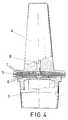
- the membrane, or membraneswill have to be located in the outlet end, or dropper, of the dose dispenser.
- the present inventionproposes a way how to place the membrane or membranes in the dropper of the dose dispenser.
- the support projections for the membranecan be materialized by small finger-type cylinders, distributed preferably in concentric annular alignments.
- the small cylinders that surround the axial opening for flow of the product from the main body to the containerhave their free edges joined by means of a disk-shaped partition, of the same or different material, defining a small radial diffusion chamber given that the flow of the product in an axial direction is prevented, thus this small disk acts as a deflecting element.
- these support fingers of the membraneIn the top part of the dropper, or top body of the same, there are also these support fingers of the membrane, with an identical distribution and the innermost ones having their ends likewise joined by another small disk, of an identical function and which on the other hand does not interfere with the outflow of the pharmaceutical solution.
- All this plurality of support projections for seating the filtering membranescan also be achieved upon providing a plurality of concentric annular partitions equidistant to each other, there being some radial or diametric cuts that form in the same passage or intercommunication ducts between the chambers formed between said annular partitions, thus obtaining a good dispersion of flow through the entire surface of the membrane.
- the bottom body of the dropperis the element which can include the inside thread for connection to the neck of the container, having on its bottom end the sealing ring. It is also provided for that it is not necessary to include the cited thread and that this bottom body of the dropper were to fit by pressure on the neck of the container, though the corresponding sealing ring were included.
- the outlet mouth of the curative product, formed in the top part of the dropperadvantageously includes an outside thread for anchoring a small sealing cover of said mouth, likewise provided with a sealing ring that remains locked in the corresponding toothing provided for opposite the dropper.
- a dose dispenser included in the present inventionhas a container (1) of a material easily deformable by pressure, a thread cap (2) with its corresponding sealing ring, a dropper divided in two parts, a bottom one (3) and another top one (4) and, finally the membrane or membranes (5) that are located between the cited two parts (3) and (4) of the dropper.
- the liquid that passes through the membrane substantially preservative-freerises through the inside center reverse truncated-cone shaped cavity (8) of the top part (4) of the dropper until the outside.
- the air itself that enters through the center hole (8) of the top part (4) to counteract the vacuum produced by the liquid removedpushes the membrane downward which remains supported on the bottom cylinder unit of part (3) of the dropper, leaving a cavity through which the liquid retained in the duct (8) spreads again through the membrane and between the spaces existing between the cylinders (6 ), going back inside the container for its preservation.
- the containerrecovers its initial shape and no liquid remains in the top part of the dropper which could be easily contaminated upon being substantially preservative-free.
- the operation describedis repeated as many times as necessary during the patient's treatment with a total guarantee of preservation and easy application.
- the container (1)is susceptible to contract but there is no danger of contamination of the solution.
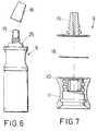
- the new dose dispensorthat is proposed includes a dropper generally referred to as number (9), whose bottom body (10) includes an annular flap (11) that immobilizes the neck (12) of the container (1), including the sealing ring (13) that immobilizes the sawtoothing (14) of the neck of the container (1.)
- a droppergenerally referred to as number (9)
- the bottom body10
- the sealing ring(13) that immobilizes the sawtoothing (14) of the neck of the container (1.
- the top body of the dropper (9)is referred to as number (15) and its dose mouth remains closed with the sealing cap (16) upon including a thread (17.)
- sealing cap (16)also provided with a sealing ring (25.)
Landscapes
- Health & Medical Sciences (AREA)
- Veterinary Medicine (AREA)
- Life Sciences & Earth Sciences (AREA)
- Animal Behavior & Ethology (AREA)
- General Health & Medical Sciences (AREA)
- Public Health (AREA)
- Pharmacology & Pharmacy (AREA)
- Medical Preparation Storing Or Oral Administration Devices (AREA)
- Closures For Containers (AREA)
- Separation Using Semi-Permeable Membranes (AREA)
- Compositions Of Macromolecular Compounds (AREA)
- Feeding, Discharge, Calcimining, Fusing, And Gas-Generation Devices (AREA)
- Manufacture Of Macromolecular Shaped Articles (AREA)
Abstract
Description

- alkyl, alkylene, alkyl or aryl groups;
- identical or different;
- substituted or unsubstituted;
- branched or unbranched;
- cyclic or linear;
- that main contain ether, ester or amide bonds;
Claims (22)
- Use of polymeric membranes in the dispensing ofa pharmaceutical solution containing an active product,wherein at least one polymeric membrane is placed in adropper portion of a dose dispenser housing said pharmaceuticalsolution,
characterized in thatsaid at least one polymeric membrane is used topermit the flow of essentially all of the active productand to retain essentially all of a preservative comprisinga quaternary ammonium compound, during pharmacologicaltreatment with said pharmaceutical solution. - Use according to claim 1, wherein the polymericmembrane is a membrane of cellulose triacetate.
- Use according to claim 1, wherein the polymericmembrane is a membrane of cellulose nitrate.
- Use according to claim 1, wherein the polymericmembrane is a membrane of regenerated cellulose.
- Use according to claim 1, wherein the polymericmembrane is a membrane of nylon.
- Use according to claim 1, wherein the polymericmembrane is a membrane of polyvinylidene flouride.
- Use according to claim 1, wherein the polymericmembrane is a membrane of silicone.
- Use according to claim 1, wherein the polymericmembrane is a membrane of polysulfone.
- Use according to claim 1, wherein the polymericmembrane is a membrane of polycarbonate.
- Dose dispenser for pharmaceutical solutionscomprising:a container (1) of a material easily deformable bypressure;a thread cap (2,16) with its corresponding sealingring; anda dropper having a bottom part (3,10) and a top part (4,15) between which at least one polymeric membrane (5,18)is housed, the bottom part including a first cylinder unit(6) and the top part including a second cylinder unit (7)disposed such that said cylinder units (6,7) may come incontact with said at least one polymeric membrane (5,18);
characterized that there is sufficient free spacebetween said first cylinder unit (6) and said secondcylinder unit (7), in order to allow for movement of saidat least one polymeric membrane (5,18) between an upperposition and a lower position, wherein in the lowerposition air is permitted to flow around the membrane andinto the container. - Dose dispenser according to claim 10,wherein the cylinder units (6,7) represent projections (19)which establish ducts that permit the pharmaceuticalsolution to pass from an axial hole (22) of the bottom part(10), the bottom part (10) of the dropper including a flap(11) for immobilization of said part on the outside of aneck (12) of the container (1), by insertion or optionallyby thread, permitting the increase of the diameter of theat least one polymeric membrane (18) and therefore of thesurface of the projections (19) that support said at leastone membrane (18), making the surface of the membranelarger than the cross section area of the mouth and neck ofthe container (1), the bottom part (10) further includinga sealing ring (13).
- Dose dispenser according to claim 11, whereinthe projections (19) are embodied by a plurality ofcylinder-like projections disposed in a concentric annularalignment and, in the center portion of the top part aswell as of the bottom part, small disks (24) situated overthe axial hole (22), acting as deflecting elements in orderto avoid deformation of the membrane in that area.
- Dose dispenser according to claim 11, whereinthe projections (19) comprise concentric annular partitions establishing chambers, there being radial or diametric cutsin said partitions in order to provide for fluid communicationbetween said chambers, allowing a good dispersion offlow through the entire surface of the at least onepolymeric membrane (18), there being a small wall (24) ofcover of the innermost discontinuous annular partition, inorder to prevent the membrane from wear or from breaking.
- Dose dispenser according to any of claims 11-13,characterized in that the top part (15) includes athread (17) and immobilization means for the sealing ring(25) of the cover (16).
- Dose dispenser according to any of claims 10-14,wherein the at least one polymeric membrane includes amembrane of cellulose triacetate.
- Dose dispenser according to any of claims 10-14,wherein the at least one polymeric membrane includes amembrane of cellulose nitrate.
- Dose dispenser according to any of claims 10-14,wherein the at least one polymeric membrane includes amembrane of regenerated cellulose.
- Dose dispenser according to any of claims 10-14,wherein the at least one polymeric membrane includes amembrane of nylon.
- Dose dispenser according to any of claims 10-14,wherein the at least one polymeric membrane includes amembrane of polyvinylidene flouride.
- Dose dispenser according to any of claims 10-14,wherein the at least one polymeric membrane includes amembrane of silicone.
- Dose dispenser according to any of claims 10-14,wherein the at least one polymeric membrane includes amembrane of polysulfone.
- Dose dispenser according to any of claims 10-14,wherein the at least one polymeric membrane includes amembrane of polycarbonate.
Applications Claiming Priority (4)
| Application Number | Priority Date | Filing Date | Title |
|---|---|---|---|
| ES9301443 | 1993-06-25 | ||
| ES9301443AES2064286B1 (en) | 1993-06-25 | 1993-06-25 | NEW APPLICATION OF POLYMERIC MEMBRANES IN THE DISPENSATION OF PHARMACEUTICAL SOLUTIONS CONTAINING QUATERNARY AMMONIUM COMPOUNDS AS CONSERVATIVES AND THE CORRESPONDING DISPENSER CONTAINER. |
| ES9401260 | 1994-06-09 | ||
| ES9401260AES2119588B1 (en) | 1993-06-25 | 1994-06-09 | IMPROVEMENTS INTRODUCED IN THE INVENTION PATENT N-P 9301443/0, BY: NEW APPLICATION OF POLYMERIC MEMBRANES IN THE DISPENSATION OF PHARMACEUTICAL SOLUTIONS CONTAINING QUATERNARY AMMONIUM COMPOUNDS AS CONSERVATIVES, AND CORRESPONDING DOSAGE CONTAINER. |
Publications (2)
| Publication Number | Publication Date |
|---|---|
| EP0631770A1 EP0631770A1 (en) | 1995-01-04 |
| EP0631770B1true EP0631770B1 (en) | 1998-07-22 |
Family
ID=26154731
Family Applications (1)
| Application Number | Title | Priority Date | Filing Date |
|---|---|---|---|
| EP19940201823Expired - LifetimeEP0631770B1 (en) | 1993-06-25 | 1994-06-23 | New use of polymeric membranes in the dispensing of pharmaceutical solutions that contain quaternary ammonium compounds as preservatives and corresponding dose dispensor |
Country Status (9)
| Country | Link |
|---|---|
| US (1) | US5588559A (en) |
| EP (1) | EP0631770B1 (en) |
| JP (1) | JP2736227B2 (en) |
| CN (1) | CN1105230A (en) |
| AT (1) | ATE168553T1 (en) |
| AU (1) | AU671743B2 (en) |
| CA (1) | CA2126703C (en) |
| DE (1) | DE69411816T2 (en) |
| FI (1) | FI108514B (en) |
Families Citing this family (39)
| Publication number | Priority date | Publication date | Assignee | Title |
|---|---|---|---|---|
| DE29609396U1 (en)* | 1996-05-25 | 1996-09-26 | Moormann, Frank, 49377 Vechta | Dispensing device for keeping sterile and dispensing liquids |
| US6076709A (en)* | 1998-05-04 | 2000-06-20 | Dentsply Detrey G.M.B.H. | Dental adhesive container dropping system |
| US6168581B1 (en)* | 1999-02-09 | 2001-01-02 | Comar, Inc. | Drop dispensers |
| US6632202B1 (en)* | 1999-03-16 | 2003-10-14 | James Hagele | Precision release eye dropper bottle |
| US6197008B1 (en)* | 1999-05-26 | 2001-03-06 | James Hagele | Precise instilation eye dropper tip |
| US6632681B1 (en) | 2000-07-24 | 2003-10-14 | Ey Laboratories | Reagent delivery device and method of use |
| FR2816600B1 (en)* | 2000-11-13 | 2003-03-21 | Michel Faurie | DISPENSING DEVICE FOR DROP FLUID LIQUIDS |
| DE10112332C1 (en)* | 2001-03-13 | 2002-08-29 | Stella Kunststofftechnik Gmbh | Drip cap for dosing liquid in drop form and container with drip cap |
| DE10147799C1 (en)* | 2001-09-27 | 2003-04-03 | Buender Glas Gmbh | Dropper, especially eye dropper |
| US20040127861A1 (en)* | 2002-12-26 | 2004-07-01 | Bradley Pharmaceuticals, Inc. | Method and apparatus for dispensing a composition |
| US8403176B2 (en)* | 2003-01-22 | 2013-03-26 | Allergan, Inc. | Controlled drop dispensing container |
| US20050043693A1 (en)* | 2003-03-31 | 2005-02-24 | Infantolino Angelo Michael | Easy drop |
| US20050194410A1 (en)* | 2004-03-08 | 2005-09-08 | Tuan Pham | Stopper for a bottle pourer |
| FR2872137B1 (en)* | 2004-06-24 | 2009-01-23 | Thea Sa Lab | CONTAINER FOR THE CONDITIONING OF A LIQUID WITH A DROPPER FLOW DISTRIBUTOR WITH REVERSIBLE DEFORMATION BY AIR INTAKE |
| ATE412400T1 (en)* | 2004-11-09 | 2008-11-15 | Novagali Pharma Sa | OIL-IN-WATER EMULSION WITH LOW CATIONIC AGENT CONCENTRATION AND POSITIVE ZETA POTENTIAL |
| CA111438S (en)* | 2005-05-23 | 2006-12-22 | Rexam Dispensing Sys | NASAL SPRAYER |
| US7537141B1 (en)* | 2005-07-26 | 2009-05-26 | Rexam Closure Systems Inc. | Dispensing closure and package |
| FR2897599B1 (en)* | 2006-02-23 | 2010-08-27 | Rexam Pharma | LIQUID CONDITIONING AND DISPENSING ASSEMBLY. |
| WO2008035246A2 (en) | 2006-07-28 | 2008-03-27 | Novagali Pharma Sa | Compositions containing quaternary ammonium compounds |
| FR2908043B1 (en)* | 2006-11-03 | 2009-01-23 | Prevor Internat Sarl | PORTABLE INDIVIDUAL DEVICE FOR EYE BATH |
| JP4869039B2 (en)* | 2006-11-27 | 2012-02-01 | ニプロ株式会社 | Chemical container |
| EP2228058A1 (en) | 2009-03-04 | 2010-09-15 | Novagali Pharma S.A. | Anionic oil-in-water emulsion containing prostaglandins and uses thereof |
| EP2389939A1 (en) | 2010-05-28 | 2011-11-30 | Novagali Pharma S.A. | Use of prostaglandins F2alpha and analogues for the healing of corneal and conjunctival lesions |
| EP2361599A1 (en)* | 2010-02-22 | 2011-08-31 | Fresenius Kabi Deutschland GmbH | Device for supplying or removing a liquid into or out of a container |
| FR2963329B1 (en)* | 2010-07-30 | 2013-06-28 | Thea Lab | HEAD FOR DISPENSING A DROP FLUID LIQUID |
| US20120312840A1 (en)* | 2011-05-13 | 2012-12-13 | Ayako Hasegawa | Container closure system with integral antimicrobial additives |
| KR101554189B1 (en)* | 2013-12-10 | 2015-09-21 | (주)연우 | Tube type cosmetic vessel exhausting into the form of water drop |
| USD770287S1 (en)* | 2014-02-27 | 2016-11-01 | Ivoclar Vivadent Ag | Bottle |
| USD733286S1 (en)* | 2014-04-30 | 2015-06-30 | Meadwestvaco Corporation | Pump with locking sleeve |
| JP6660939B2 (en) | 2014-08-13 | 2020-03-11 | ユニバーシティ オブ フロリダ リサーチ ファンデーション インコーポレーティッド | Preservative removal from eye drops |
| CN104307584B (en)* | 2014-09-25 | 2015-09-16 | 瑞安市富日包装机械有限公司 | Dropper unit mahine |
| WO2017151624A1 (en)* | 2016-02-29 | 2017-09-08 | Distek, Inc. | Sample probe for dissolution testing and the like |
| AU2017366761B2 (en) | 2016-12-02 | 2023-06-15 | University Of Florida Research Foundation, Inc. | Preservative removal from eye drops |
| TW202005623A (en) | 2018-04-06 | 2020-02-01 | 美商蒂克利爾公司 | Systems and methods for delivery of a therapeutic agent |
| CN113891697B (en)* | 2019-03-28 | 2025-03-18 | 特清公司 | Device and method for flow control of ophthalmic preparations |
| CN114096339B (en)* | 2019-05-02 | 2024-04-12 | 特清公司 | Removal of preservatives from eye drops |
| CN110683173B (en)* | 2019-11-01 | 2024-08-23 | 安徽创孚医疗科技有限公司 | Deoxidizing and freezing device |
| CA3165110A1 (en) | 2019-12-19 | 2021-06-24 | Michael S. Williams | Preservative removal from eye drops |
| US11931749B2 (en)* | 2022-08-03 | 2024-03-19 | Gerresheimer Boleslawiec Spolka Akcyjna | Dispenser for dispensing liquids |
Family Cites Families (24)
| Publication number | Priority date | Publication date | Assignee | Title |
|---|---|---|---|---|
| DE2809321B2 (en)* | 1978-03-03 | 1980-04-24 | Carl Schleicher & Schuell Gmbh & Co Kg, 3352 Einbeck | Disposable filter housing |
| FR2422569A1 (en)* | 1978-04-14 | 1979-11-09 | Roussel Uclaf | STERILE LIQUID DISPENSER |
| DE3242359A1 (en)* | 1981-12-08 | 1983-07-21 | Smiths Industries Public Ltd. Co., London | FILTER COMPONENT |
| US4463880A (en)* | 1982-04-30 | 1984-08-07 | The Regents Of The University Of California | Medicine drop dispenser with anti-bacterial filter |
| JPS59194751A (en)* | 1983-04-19 | 1984-11-05 | 帝国臓器製薬株式会社 | drop bottle |
| JPS61206445A (en)* | 1985-03-11 | 1986-09-12 | テルモ株式会社 | Air passing needle and its production |
| US4846810A (en)* | 1987-07-13 | 1989-07-11 | Reseal International Limited Partnership | Valve assembly |
| FR2638428B1 (en)* | 1988-10-28 | 1990-12-28 | Transphyto Sa | PACKAGING FOR PURIFYING LIQUIDS |
| US4938389A (en)* | 1988-11-03 | 1990-07-03 | Eye Research Institute Of Retina Foundation | Filter bottle |
| US5219101A (en)* | 1989-06-01 | 1993-06-15 | Pall Corporation | Contamination-resistant dispensing and metering drop forming device |
| GB9011455D0 (en)* | 1989-06-01 | 1990-07-11 | Pall Corp | Contamination-resistant dispensing and metering device |
| US5265770A (en)* | 1989-06-01 | 1993-11-30 | Pall Corporation | Contamination-resistant dispensing and metering device |
| US5105993A (en)* | 1989-12-29 | 1992-04-21 | La Haye Laboratories, Inc. | Disposable medical dispenser with a filtering dispenser nozzle |
| US5056689A (en)* | 1990-01-08 | 1991-10-15 | Ciba-Geigy Corporation | Apparatus for removing components from solutions |
| US5373971A (en)* | 1990-01-11 | 1994-12-20 | Laffy; Raoul | Aseptic container for holding and dispensing a sterile liquid or semi-liquid product |
| FR2661401B1 (en)* | 1990-04-27 | 1992-07-24 | Transphyto Sa | PACKAGING PROCESS FOR STORING AND DISPENSING BY PORTIONS OF STERILE LIQUID. |
| US5074440A (en)* | 1990-07-16 | 1991-12-24 | Alcon Laboratories, Inc. | Container for dispensing preservative-free preparations |
| CA2025105A1 (en)* | 1990-09-11 | 1992-03-12 | Garth T. Webb | Device for storing and dispensing sterile liquids |
| US5238153A (en)* | 1991-02-19 | 1993-08-24 | Pilkington Visioncare Inc. | Dispenser for dispersing sterile solutions |
| FR2678905B1 (en)* | 1991-07-10 | 1995-01-27 | Kerplas Snc | DRIP TIP. |
| US5310094A (en)* | 1991-11-15 | 1994-05-10 | Jsp Partners, L.P. | Preservative free sterile fluid dispensing system |
| ES1019546Y (en)* | 1991-12-05 | 1992-11-01 | Grifols Lucas Victor | PERFUSION LIQUID BAG, PERFECTED. |
| US5269917A (en)* | 1992-02-28 | 1993-12-14 | Millipore Corporation | Filtration apparatus having stress relief groove |
| TW205503B (en)* | 1992-04-24 | 1993-05-11 | Ciba Geigy Ag | Apparatus for removing components from solutions |
- 1994
- 1994-06-23EPEP19940201823patent/EP0631770B1/ennot_activeExpired - Lifetime
- 1994-06-23FIFI943066Apatent/FI108514B/enactive
- 1994-06-23ATAT94201823Tpatent/ATE168553T1/ennot_activeIP Right Cessation
- 1994-06-23DEDE69411816Tpatent/DE69411816T2/ennot_activeExpired - Fee Related
- 1994-06-24CACA 2126703patent/CA2126703C/ennot_activeExpired - Fee Related
- 1994-06-24USUS08/265,409patent/US5588559A/ennot_activeExpired - Lifetime
- 1994-06-24CNCN94108914Apatent/CN1105230A/enactivePending
- 1994-06-27AUAU66007/94Apatent/AU671743B2/ennot_activeCeased
- 1994-06-27JPJP14473294Apatent/JP2736227B2/ennot_activeExpired - Fee Related
Also Published As
| Publication number | Publication date |
|---|---|
| JPH07171193A (en) | 1995-07-11 |
| JP2736227B2 (en) | 1998-04-02 |
| CA2126703C (en) | 1999-08-17 |
| DE69411816D1 (en) | 1998-08-27 |
| AU6600794A (en) | 1995-01-05 |
| FI943066A0 (en) | 1994-06-23 |
| CN1105230A (en) | 1995-07-19 |
| ATE168553T1 (en) | 1998-08-15 |
| US5588559A (en) | 1996-12-31 |
| FI943066A7 (en) | 1994-12-26 |
| FI108514B (en) | 2002-02-15 |
| EP0631770A1 (en) | 1995-01-04 |
| CA2126703A1 (en) | 1994-12-26 |
| AU671743B2 (en) | 1996-09-05 |
| DE69411816T2 (en) | 1998-12-03 |
Similar Documents
| Publication | Publication Date | Title |
|---|---|---|
| EP0631770B1 (en) | New use of polymeric membranes in the dispensing of pharmaceutical solutions that contain quaternary ammonium compounds as preservatives and corresponding dose dispensor | |
| US5105993A (en) | Disposable medical dispenser with a filtering dispenser nozzle | |
| US4938389A (en) | Filter bottle | |
| US5310094A (en) | Preservative free sterile fluid dispensing system | |
| US5373972A (en) | Preservative-free sterile fluid dispensing system | |
| EP0439999B2 (en) | Apparatus for removing preservatives from solutions | |
| US5265770A (en) | Contamination-resistant dispensing and metering device | |
| EP0644785B1 (en) | Arrangement for dispensing preservative-free nasal sprays and similar preparations | |
| JPH05500937A (en) | Containers for dispensing preservative-free preparations | |
| EP1008358A2 (en) | Infusion filter | |
| EP0459498B1 (en) | Contamination-resistant dispensing and metering device | |
| CN107531370A (en) | Liquid dispensing device for aseptic packaging bottles | |
| EP2389956B1 (en) | Contact lens cases for delivery of ophthalmic agents | |
| AU643404B2 (en) | Double tip drug dispensing and metering device | |
| CA2819305C (en) | A device for packaging, conserving, and extemporaneously preparing a plurality of active principles | |
| GB2132989A (en) | Hand-held liquid filtering and dispensing device | |
| US20250041215A1 (en) | Multidose preservative-free (mdpf) ophthalmic dose delivery with addition of formulation surfactants | |
| JPH063808Y2 (en) | Secondary contamination prevention cap for eye drops | |
| JPH0361461B2 (en) | ||
| CN118122514A (en) | Aseptic liquid medicine dispenser | |
| TW201811290A (en) | Sterile liquid dispenser | |
| HK1027060A1 (en) | Flask for dispensing liquid, cream or gel comprising a device for filtering incoming air | |
| HK1027060B (en) | Flask for dispensing liquid, cream or gel comprising a device for filtering incoming air |
Legal Events
| Date | Code | Title | Description |
|---|---|---|---|
| PUAI | Public reference made under article 153(3) epc to a published international application that has entered the european phase | Free format text:ORIGINAL CODE: 0009012 | |
| AK | Designated contracting states | Kind code of ref document:A1 Designated state(s):AT BE CH DE DK FR GB GR IE IT LI LU MC NL PT SE | |
| 17P | Request for examination filed | Effective date:19950524 | |
| 17Q | First examination report despatched | Effective date:19970110 | |
| GRAG | Despatch of communication of intention to grant | Free format text:ORIGINAL CODE: EPIDOS AGRA | |
| GRAG | Despatch of communication of intention to grant | Free format text:ORIGINAL CODE: EPIDOS AGRA | |
| GRAH | Despatch of communication of intention to grant a patent | Free format text:ORIGINAL CODE: EPIDOS IGRA | |
| GRAH | Despatch of communication of intention to grant a patent | Free format text:ORIGINAL CODE: EPIDOS IGRA | |
| RAP1 | Party data changed (applicant data changed or rights of an application transferred) | Owner name:ALCON CUSI, S.A. | |
| GRAA | (expected) grant | Free format text:ORIGINAL CODE: 0009210 | |
| AK | Designated contracting states | Kind code of ref document:B1 Designated state(s):AT BE CH DE DK FR GB GR IE IT LI LU MC NL PT SE | |
| PG25 | Lapsed in a contracting state [announced via postgrant information from national office to epo] | Ref country code:NL Free format text:LAPSE BECAUSE OF FAILURE TO SUBMIT A TRANSLATION OF THE DESCRIPTION OR TO PAY THE FEE WITHIN THE PRESCRIBED TIME-LIMIT Effective date:19980722 Ref country code:LI Free format text:LAPSE BECAUSE OF FAILURE TO SUBMIT A TRANSLATION OF THE DESCRIPTION OR TO PAY THE FEE WITHIN THE PRESCRIBED TIME-LIMIT Effective date:19980722 Ref country code:GR Free format text:LAPSE BECAUSE OF NON-PAYMENT OF DUE FEES Effective date:19980722 Ref country code:CH Free format text:LAPSE BECAUSE OF FAILURE TO SUBMIT A TRANSLATION OF THE DESCRIPTION OR TO PAY THE FEE WITHIN THE PRESCRIBED TIME-LIMIT Effective date:19980722 Ref country code:BE Free format text:LAPSE BECAUSE OF FAILURE TO SUBMIT A TRANSLATION OF THE DESCRIPTION OR TO PAY THE FEE WITHIN THE PRESCRIBED TIME-LIMIT Effective date:19980722 Ref country code:AT Free format text:LAPSE BECAUSE OF FAILURE TO SUBMIT A TRANSLATION OF THE DESCRIPTION OR TO PAY THE FEE WITHIN THE PRESCRIBED TIME-LIMIT Effective date:19980722 | |
| REF | Corresponds to: | Ref document number:168553 Country of ref document:AT Date of ref document:19980815 Kind code of ref document:T | |
| REG | Reference to a national code | Ref country code:CH Ref legal event code:EP | |
| REF | Corresponds to: | Ref document number:69411816 Country of ref document:DE Date of ref document:19980827 | |
| PG25 | Lapsed in a contracting state [announced via postgrant information from national office to epo] | Ref country code:SE Free format text:LAPSE BECAUSE OF FAILURE TO SUBMIT A TRANSLATION OF THE DESCRIPTION OR TO PAY THE FEE WITHIN THE PRESCRIBED TIME-LIMIT Effective date:19981022 Ref country code:PT Free format text:LAPSE BECAUSE OF FAILURE TO SUBMIT A TRANSLATION OF THE DESCRIPTION OR TO PAY THE FEE WITHIN THE PRESCRIBED TIME-LIMIT Effective date:19981022 Ref country code:DK Free format text:LAPSE BECAUSE OF FAILURE TO SUBMIT A TRANSLATION OF THE DESCRIPTION OR TO PAY THE FEE WITHIN THE PRESCRIBED TIME-LIMIT Effective date:19981022 | |
| REG | Reference to a national code | Ref country code:IE Ref legal event code:FG4D | |
| ET | Fr: translation filed | ||
| NLV1 | Nl: lapsed or annulled due to failure to fulfill the requirements of art. 29p and 29m of the patents act | ||
| REG | Reference to a national code | Ref country code:CH Ref legal event code:PL | |
| PLBE | No opposition filed within time limit | Free format text:ORIGINAL CODE: 0009261 | |
| STAA | Information on the status of an ep patent application or granted ep patent | Free format text:STATUS: NO OPPOSITION FILED WITHIN TIME LIMIT | |
| PG25 | Lapsed in a contracting state [announced via postgrant information from national office to epo] | Ref country code:LU Free format text:LAPSE BECAUSE OF NON-PAYMENT OF DUE FEES Effective date:19990623 | |
| 26N | No opposition filed | ||
| PG25 | Lapsed in a contracting state [announced via postgrant information from national office to epo] | Ref country code:MC Free format text:LAPSE BECAUSE OF NON-PAYMENT OF DUE FEES Effective date:19991231 | |
| REG | Reference to a national code | Ref country code:GB Ref legal event code:IF02 | |
| PGFP | Annual fee paid to national office [announced via postgrant information from national office to epo] | Ref country code:IE Payment date:20090626 Year of fee payment:16 | |
| PGFP | Annual fee paid to national office [announced via postgrant information from national office to epo] | Ref country code:FR Payment date:20090617 Year of fee payment:16 | |
| PGFP | Annual fee paid to national office [announced via postgrant information from national office to epo] | Ref country code:GB Payment date:20090625 Year of fee payment:16 Ref country code:DE Payment date:20090629 Year of fee payment:16 | |
| PGFP | Annual fee paid to national office [announced via postgrant information from national office to epo] | Ref country code:IT Payment date:20090629 Year of fee payment:16 | |
| GBPC | Gb: european patent ceased through non-payment of renewal fee | Effective date:20100623 | |
| REG | Reference to a national code | Ref country code:FR Ref legal event code:ST Effective date:20110228 | |
| REG | Reference to a national code | Ref country code:IE Ref legal event code:MM4A | |
| PG25 | Lapsed in a contracting state [announced via postgrant information from national office to epo] | Ref country code:IT Free format text:LAPSE BECAUSE OF NON-PAYMENT OF DUE FEES Effective date:20100623 | |
| PG25 | Lapsed in a contracting state [announced via postgrant information from national office to epo] | Ref country code:IE Free format text:LAPSE BECAUSE OF NON-PAYMENT OF DUE FEES Effective date:20100623 Ref country code:DE Free format text:LAPSE BECAUSE OF NON-PAYMENT OF DUE FEES Effective date:20110101 | |
| PG25 | Lapsed in a contracting state [announced via postgrant information from national office to epo] | Ref country code:FR Free format text:LAPSE BECAUSE OF NON-PAYMENT OF DUE FEES Effective date:20100630 | |
| PG25 | Lapsed in a contracting state [announced via postgrant information from national office to epo] | Ref country code:GB Free format text:LAPSE BECAUSE OF NON-PAYMENT OF DUE FEES Effective date:20100623 |