EP0629419B1 - Composite iron golf club - Google Patents
Composite iron golf clubDownload PDFInfo
- Publication number
- EP0629419B1 EP0629419B1EP94108411AEP94108411AEP0629419B1EP 0629419 B1EP0629419 B1EP 0629419B1EP 94108411 AEP94108411 AEP 94108411AEP 94108411 AEP94108411 AEP 94108411AEP 0629419 B1EP0629419 B1EP 0629419B1
- Authority
- EP
- European Patent Office
- Prior art keywords
- blade
- clubhead
- hosel
- weight
- bracket
- Prior art date
- Legal status (The legal status is an assumption and is not a legal conclusion. Google has not performed a legal analysis and makes no representation as to the accuracy of the status listed.)
- Expired - Lifetime
Links
- XEEYBQQBJWHFJM-UHFFFAOYSA-NIronChemical compound[Fe]XEEYBQQBJWHFJM-UHFFFAOYSA-N0.000titleclaimsdescription29
- 229910052742ironInorganic materials0.000titleclaimsdescription15
- 239000002131composite materialSubstances0.000titledescription4
- 239000000463materialSubstances0.000claimsdescription26
- 238000009826distributionMethods0.000description7
- OKTJSMMVPCPJKN-UHFFFAOYSA-NCarbonChemical compound[C]OKTJSMMVPCPJKN-UHFFFAOYSA-N0.000description2
- 229910000831SteelInorganic materials0.000description2
- 229910052782aluminiumInorganic materials0.000description2
- XAGFODPZIPBFFR-UHFFFAOYSA-NaluminiumChemical compound[Al]XAGFODPZIPBFFR-UHFFFAOYSA-N0.000description2
- 230000000694effectsEffects0.000description2
- 239000000835fiberSubstances0.000description2
- 229910002804graphiteInorganic materials0.000description2
- 239000010439graphiteSubstances0.000description2
- 229910052751metalInorganic materials0.000description2
- 239000002184metalSubstances0.000description2
- 239000010959steelSubstances0.000description2
- RYGMFSIKBFXOCR-UHFFFAOYSA-NCopperChemical compound[Cu]RYGMFSIKBFXOCR-UHFFFAOYSA-N0.000description1
- 229910000881Cu alloyInorganic materials0.000description1
- 239000004593EpoxySubstances0.000description1
- RTAQQCXQSZGOHL-UHFFFAOYSA-NTitaniumChemical compound[Ti]RTAQQCXQSZGOHL-UHFFFAOYSA-N0.000description1
- 230000002411adverseEffects0.000description1
- DMFGNRRURHSENX-UHFFFAOYSA-Nberyllium copperChemical compound[Be].[Cu]DMFGNRRURHSENX-UHFFFAOYSA-N0.000description1
- 230000015572biosynthetic processEffects0.000description1
- 238000005219brazingMethods0.000description1
- 238000005266castingMethods0.000description1
- 229910052802copperInorganic materials0.000description1
- 239000010949copperSubstances0.000description1
- 238000005260corrosionMethods0.000description1
- 230000007797corrosionEffects0.000description1
- -1e.g.Substances0.000description1
- 239000003822epoxy resinSubstances0.000description1
- 239000003733fiber-reinforced compositeSubstances0.000description1
- 238000005242forgingMethods0.000description1
- 230000005484gravityEffects0.000description1
- 150000002505ironChemical class0.000description1
- 235000000396ironNutrition0.000description1
- 238000004519manufacturing processMethods0.000description1
- 229910001092metal group alloyInorganic materials0.000description1
- 238000000034methodMethods0.000description1
- 239000012768molten materialSubstances0.000description1
- 229920000647polyepoxidePolymers0.000description1
- 229920005989resinPolymers0.000description1
- 239000011347resinSubstances0.000description1
- 239000007779soft materialSubstances0.000description1
- 239000010935stainless steelSubstances0.000description1
- 229910001220stainless steelInorganic materials0.000description1
- 239000010936titaniumSubstances0.000description1
- 229910052719titaniumInorganic materials0.000description1
- 238000003466weldingMethods0.000description1
Images


Classifications
- A—HUMAN NECESSITIES
- A63—SPORTS; GAMES; AMUSEMENTS
- A63B—APPARATUS FOR PHYSICAL TRAINING, GYMNASTICS, SWIMMING, CLIMBING, OR FENCING; BALL GAMES; TRAINING EQUIPMENT
- A63B53/00—Golf clubs
- A63B53/04—Heads
- A—HUMAN NECESSITIES
- A63—SPORTS; GAMES; AMUSEMENTS
- A63B—APPARATUS FOR PHYSICAL TRAINING, GYMNASTICS, SWIMMING, CLIMBING, OR FENCING; BALL GAMES; TRAINING EQUIPMENT
- A63B53/00—Golf clubs
- A63B53/04—Heads
- A63B53/0416—Heads having an impact surface provided by a face insert
- A—HUMAN NECESSITIES
- A63—SPORTS; GAMES; AMUSEMENTS
- A63B—APPARATUS FOR PHYSICAL TRAINING, GYMNASTICS, SWIMMING, CLIMBING, OR FENCING; BALL GAMES; TRAINING EQUIPMENT
- A63B53/00—Golf clubs
- A63B53/04—Heads
- A63B53/0445—Details of grooves or the like on the impact surface
- A—HUMAN NECESSITIES
- A63—SPORTS; GAMES; AMUSEMENTS
- A63B—APPARATUS FOR PHYSICAL TRAINING, GYMNASTICS, SWIMMING, CLIMBING, OR FENCING; BALL GAMES; TRAINING EQUIPMENT
- A63B53/00—Golf clubs
- A63B53/04—Heads
- A63B53/047—Heads iron-type
- A—HUMAN NECESSITIES
- A63—SPORTS; GAMES; AMUSEMENTS
- A63B—APPARATUS FOR PHYSICAL TRAINING, GYMNASTICS, SWIMMING, CLIMBING, OR FENCING; BALL GAMES; TRAINING EQUIPMENT
- A63B60/00—Details or accessories of golf clubs, bats, rackets or the like
- A—HUMAN NECESSITIES
- A63—SPORTS; GAMES; AMUSEMENTS
- A63F—CARD, BOARD, OR ROULETTE GAMES; INDOOR GAMES USING SMALL MOVING PLAYING BODIES; VIDEO GAMES; GAMES NOT OTHERWISE PROVIDED FOR
- A63F7/00—Indoor games using small moving playing bodies, e.g. balls, discs or blocks
- A63F7/22—Accessories; Details
- A63F7/36—Constructional details not covered by groups A63F7/24 - A63F7/34, i.e. constructional details of rolling boards, rims or play tables, e.g. frame, game boards, guide tracks
- A63F2007/3674—Details of play tables, designed as a table
- Y—GENERAL TAGGING OF NEW TECHNOLOGICAL DEVELOPMENTS; GENERAL TAGGING OF CROSS-SECTIONAL TECHNOLOGIES SPANNING OVER SEVERAL SECTIONS OF THE IPC; TECHNICAL SUBJECTS COVERED BY FORMER USPC CROSS-REFERENCE ART COLLECTIONS [XRACs] AND DIGESTS
- Y10—TECHNICAL SUBJECTS COVERED BY FORMER USPC
- Y10S—TECHNICAL SUBJECTS COVERED BY FORMER USPC CROSS-REFERENCE ART COLLECTIONS [XRACs] AND DIGESTS
- Y10S273/00—Amusement devices: games
- Y10S273/23—High modulus filaments
Definitions
- This inventionrelates to an iron type golf clubhead according to the preamble of claim 1.
- An iron clubheadincludes a blade, which includes the club face for striking a golf ball, and a hosel, to which the shaft is secured. A junction portion connects the hosel and the blade.
- Iron clubheadsare conventionally forged or cast in a single, integral piece from metal or metal alloy.
- Some clubheadsare formed from two or more different materials.
- a metal corecan be covered with fiber-reinforced composite material, or the face and back of the clubhead can be formed from different materials.
- the hosel and junctionare generally formed integrally with a portion of the blade.
- the GB-A-2 192 795discloses a composite golf club iron head comprising a hosel for attaching the head to a shaft, a front surface defined by a heel, a sole, a toe, a topline and a backweight.
- the hosel, heel and a portion of the toeform a unitary member and are made of a material of a first weight density; the sole, backweight, remainder of the toe and a majority of the front surface are -- as a second unitary member -- formed of a material of a second weight density, said second weight density being higher than said first weight density, whereby the weight distribution of said head is greatest adjacent the centre of said front surface.
- the said first unitary memberis made of epoxy-impregnated graphite, and the second unitary member is made of steel.
- This iron clubheadis said to provide better durability, a better weight distribution, a better utilisation of the mass of the head and better control of the location of the centre of gravity which tends to reduce the likelihood of an errant shot.
- Each numbered golf ironfor example a 5 iron, has a standard weight which does not vary much between various manufacturers of golf clubs.
- a typical iron clubheadhas about 78% of its weight in the blade area and about 22% of its weight in the junction area. Ball flight and distance is affected by the weight of the blade and the manner in which the weight is distributed in the blade. The weight in the hosel and the junction area has little or no effect on the ball.
- Some clubshave redistributed weight from the hosel to the blade by forming openings or cutouts in the hosel. However, such openings interrupt the integrity of the hosel. Other clubs have reduced the length of the hosel or eliminated the hosel. However, the attachment of the shaft to the clubhead can be adversely affected.
- the inventionrefers to a composite iron clubhead in which the blade -- including a toe end and a heel end --is formed of a first material and the hosel and hosel junction are formed from a second material which is less dense than the first material. Weight is thereby taken out of the hosel and injunction and redistributed to the blade. The additional weight in the blade will have an advantageous effect on the flight and distance of the golf ball.
- the innovationcomprises a relatively flat bracket which extends from the heel end of the blade and which is thinner than the blade at the heel end, the junction portion surrounding the bracket and being secured thereto. This bracket is provided with openings through which the material of the junction portion extends.
- the said bracketincludes curved top and bottom edges.
- One embodiment of the inventionshows a clubhead in which the face is provided with parallel grooves which extend between the toe end and heel end of the blade, each groove having a toe end and a heel end, the heel end of the blade extending substantially perpendicularly to the heel ends of the grooves and being spaced about 2,54 to 5,08 mm (0.10 to 0.20 inch) from the heel ends of the grooves.
- the heel end of the bladeis spaced about 3,81 mm (0.15 inch) from the heel ends of the grooves.
- the weight of the bladeshould be from about 85 to 95 % of the total weight of the clubhead and the weight of the hosel and junction portion from abort 5 to 15 % of the total weight of the clubhead.
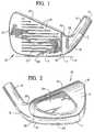
- an iron type golf clubhead 10includes a blade 11, a hosel 12, and a junction 13 which joins the hosel 12 and the blade 11.
- the hosel 12is tubular or cylindrical and is provided with a bore 14 which is adapted to receive a conventional golf club shaft. The shaft is inserted into the hosel 12 and secured therein in the conventional manner.
- the blade 11includes a toe end 15 and a heel end 16 and a flat face 17 which extends from the toe end 15 to the heel end 16. A plurality of parallel grooves 18 are formed in the face 17 in the conventional manner.
- the blade 11also includes a top edge 19, a sole 20, and a back surface 21.
- the particular clubhead 10 illustratedincludes a cavity 22 in the back surface.
- the bottom of the junction 13curves upwardly from the sole of the blade 11, and the top of the junction 13 includes a generally U-shaped notch 23.
- the grooves 18are usually designed so that they extend parallel to a ground plane G when the center of the sole rests on the ground in the proper address position.
- the toe ends of the grooves 18 and the heel ends of the groove 18are aligned along lines which extend perpendicularly to the grooves 18.
- the blade 11is formed separately from the junction 13 and the hosel 12.
- the heel end 16 of the blade 11terminates in a flat end surface 25 which extends perpendicularly to the face 17 and the grooves 18.
- a flat, thin bracket 26extends from the end surface 25 parallel to the face 17.
- the thickness of the bracket 26is constant along the length of the bracket 26 and the thickness of the bracket 26 in a direction perpendicular to the face 17 is less than the thickness of the blade 11 along the top edge 19.
- the bracket 26has a curved bottom edge 27 and a U-shaped top edge 28 which conform generally to the contour of the junction 13.
- the bracket 26terminates in a straight end edge 29.
- a plurality of openings 30are formed in the bracket 26.
- the blade 11can be formed by conventional forging or casting techniques.
- the bracket 26is formed integrally with the remainder of the blade 11, and, if necessary, suitable finishing operations can be performed on the bracket 26 to obtain the desired shape or openings 30.
- the entire bracket 26is generally planar and extends parallel to the face 17. However, for irons which have an offset hosel 12, the bracket 26 can curve forwardly beyond the face 17 so that the completed hosel 12 will have the desired offset relative to the blade 11.
- the material of the junction 13 and hosel 12is cast or otherwise formed around the bracket 26 and abuts the flat end surface 25 of the blade 11. During formation of the junction 13, the molten or soft material of the junction 13 flows through the openings 30 in the bracket 26 to form a secure interconnection between the junction 13 and the bracket 26.
- the bore of the hosel 12may be formed while the hosel 12 is formed and extends substantially to the end 29 of the bracket 26.
- the material of the junction 13 and the hosel 12can be joined to the blade 11 at the surface 25 by welding, brazing, epoxy, copper flash, or mechanical fit.
- the outer surface of the junction 13merges smoothly with the outer surface of the blade 11, and a seam line 32 is formed where the material of the junction 13 meets the material of the blade 11. If desired, the seam line 32 can be buffed to render the seam less perceptible.
- the seam line 32extends perpendicularly to the grooves 18.
- the flat end surface 25 and the seam line 32are spaced about 2,54 to 5,08 mm (0.10 to 0.20 inch), preferably about 3,81 mm (0.15 inch), from the heel ends of the grooves 18 and are substantially aligned with the intersection P (Fig. 1) between the axis or centerline CL of the hosel 12 and the ground plane G.
- the blade 11is formed from a relatively dense material, and the junction 13 and hosel 12 are formed from a less dense material so that the weight of the junction 13 and hosel 12 is less than the weight of the junction 13 and hosel 12 of a conventional club.
- the weight of the blade 11can therefore be increased while maintaining the overall weight of the clubhead within the traditional range.
- the extra weight in the blade 11can be used to increase the perimeter weighting of the cavity-backed blade 11 and/or increase the mass behind the sweetspot of the face 17.
- the material of the blade 11can be corrosion resistant stainless steel, beryllium copper alloy, or other conventional clubhead materials.
- the material of the hosel 12 and junction 13can be aluminum, titanium, composite material such as fiber reinforced resin, e.g., graphite fibers and epoxy resin, or other material which is lighter than the material of the blade 11.
- a typical number iron clubhead 10has about 78-80% of its weight in the blade area and about 20-22% of its weight in the hosel 12 and junction 13 area.
- the weight distribution of the clubhead 10can be changed so that a substantially higher percentage of the weight of the clubhead 10 is in the blade 11.
- the weight distributioncan be varied as desired so that from 80% to up to about 95% of the weight is in the blade 11 and only about 20% to 5% is in the hosel 12 and junction 13 area.
- the weight of the blade 11is between about 85 and 95% of the total weight of the clubhead 10
- the weight of the hosel 12 and junction 13is between about 5 and 15% of the total weight.
- the weight distributionis about 90% of the blade 11 and about 10% in the hosel/junction area.
- Table Idescribes the weight distribution of a prior art set of conventional Wilson Ultra iron clubheads. TABLE I Conventional Clubhead No. of Iron Total Weight (grams) weight in Blade (grams) Weight in Hosel/Junction (grams) % of Weight in Blade % of Weigh in Hosel 1 236.2 185.3 50.9 78.45 21.55 2 242.3 191.55 50.75 79.05 20.95 3 247.2 195.5 51.7 79.09 20.91 4 253.8 200.7 53.1 79.08 20.92 5 258.5 202.9 55.6 78.49 21.51 6 266.3 212.5 53.8 79.80 20.20 7 271.4 216.25 55.15 79.68 20.32 8 279.2 220.70 58.5 79.05 20.95 9 286.7 226.25 60.45 78.92 21.08 PW 296.4 235.05 61.35 79.32 20.20 Sand Wedge 322.9 253.8 69.1 78.60 21.40 60° Wedge 315.2 245.35
- the weight distribution in the blade 11 and the hosel/junction 12/13can be varied as desired while maintaining the overall weight of the clubhead 10 within the standard range.
- the clubheads in Table Iwere made from steel which has a density of 7,75 g/cm 3 (0.28 pounds per cubic inch).
- An advantageous material for the hosel/junction areais A206 aluminum, which has a density of only 2,768 g/cm 3 (0.101 pounds per cubic inch).
Landscapes
- Health & Medical Sciences (AREA)
- General Health & Medical Sciences (AREA)
- Physical Education & Sports Medicine (AREA)
- Golf Clubs (AREA)
Description
- This invention relates to an iron type golf clubhead according to the preamble of claim 1.
- An iron clubhead includes a blade, which includes the club face for striking a golf ball, and a hosel, to which the shaft is secured. A junction portion connects the hosel and the blade. Iron clubheads are conventionally forged or cast in a single, integral piece from metal or metal alloy.
- Some clubheads are formed from two or more different materials. For example, a metal core can be covered with fiber-reinforced composite material, or the face and back of the clubhead can be formed from different materials. In such cases, however, the hosel and junction are generally formed integrally with a portion of the blade.
- The GB-A-2 192 795 discloses a composite golf club iron head comprising a hosel for attaching the head to a shaft, a front surface defined by a heel, a sole, a toe, a topline and a backweight. The hosel, heel and a portion of the toe form a unitary member and are made of a material of a first weight density; the sole, backweight, remainder of the toe and a majority of the front surface are -- as a second unitary member -- formed of a material of a second weight density, said second weight density being higher than said first weight density, whereby the weight distribution of said head is greatest adjacent the centre of said front surface. The said first unitary member is made of epoxy-impregnated graphite, and the second unitary member is made of steel. This iron clubhead is said to provide better durability, a better weight distribution, a better utilisation of the mass of the head and better control of the location of the centre of gravity which tends to reduce the likelihood of an errant shot.
- Each numbered golf iron, for example a 5 iron, has a standard weight which does not vary much between various manufacturers of golf clubs. A typical iron clubhead has about 78% of its weight in the blade area and about 22% of its weight in the junction area. Ball flight and distance is affected by the weight of the blade and the manner in which the weight is distributed in the blade. The weight in the hosel and the junction area has little or no effect on the ball.
- Some clubs have redistributed weight from the hosel to the blade by forming openings or cutouts in the hosel. However, such openings interrupt the integrity of the hosel. Other clubs have reduced the length of the hosel or eliminated the hosel. However, the attachment of the shaft to the clubhead can be adversely affected.
- The invention refers to a composite iron clubhead in which the blade -- including a toe end and a heel end --is formed of a first material and the hosel and hosel junction are formed from a second material which is less dense than the first material. Weight is thereby taken out of the hosel and injunction and redistributed to the blade. The additional weight in the blade will have an advantageous effect on the flight and distance of the golf ball. The innovation comprises a relatively flat bracket which extends from the heel end of the blade and which is thinner than the blade at the heel end, the junction portion surrounding the bracket and being secured thereto. This bracket is provided with openings through which the material of the junction portion extends.
- The said bracket includes curved top and bottom edges.
- One embodiment of the invention shows a clubhead in which the face is provided with parallel grooves which extend between the toe end and heel end of the blade, each groove having a toe end and a heel end, the heel end of the blade extending substantially perpendicularly to the heel ends of the grooves and being spaced about 2,54 to 5,08 mm (0.10 to 0.20 inch) from the heel ends of the grooves.
- In addition it is found good that the heel end of the blade is spaced about 3,81 mm (0.15 inch) from the heel ends of the grooves.
- The weight of the blade should be from about 85 to 95 % of the total weight of the clubhead and the weight of the hosel and junction portion from
abort 5 to 15 % of the total weight of the clubhead. - The invention will be explained in conjunction with an illustrative embodiment shown in the accompanying drawing, in which
- Fig. 1 is a front elevational view of a clubhead formed in accordance with the invention;
- Fig. 2 is a rear elevational view of the clubhead;
- Fig. 3 is a front elevational view of the blade of the clubhead;
- Fig. 4 is a rear elevational view of the blade;
- Fig. 5 is a side elevational view of the blade taken along the line 5-5 of Fig. 3;
- Fig. 6 is a view similar to Fig. 2 with the junction portion of the clubhead broken away; and
- Fig. 7 is a view similar to Fig. 2 showing the bracket of the blade in dotted outline.
- Referring first to Fig. 1 and 2, an iron
type golf clubhead 10 includes ablade 11, ahosel 12, and ajunction 13 which joins thehosel 12 and theblade 11. Thehosel 12 is tubular or cylindrical and is provided with abore 14 which is adapted to receive a conventional golf club shaft. The shaft is inserted into thehosel 12 and secured therein in the conventional manner. - The
blade 11 includes atoe end 15 and aheel end 16 and aflat face 17 which extends from thetoe end 15 to theheel end 16. A plurality ofparallel grooves 18 are formed in theface 17 in the conventional manner. Theblade 11 also includes atop edge 19, a sole 20, and aback surface 21. Theparticular clubhead 10 illustrated includes acavity 22 in the back surface. The bottom of thejunction 13 curves upwardly from the sole of theblade 11, and the top of thejunction 13 includes a generallyU-shaped notch 23. - The
grooves 18 are usually designed so that they extend parallel to a ground plane G when the center of the sole rests on the ground in the proper address position. The toe ends of thegrooves 18 and the heel ends of thegroove 18 are aligned along lines which extend perpendicularly to thegrooves 18. - Referring now to Fig. 3 to 5, the
blade 11 is formed separately from thejunction 13 and thehosel 12. Theheel end 16 of theblade 11 terminates in aflat end surface 25 which extends perpendicularly to theface 17 and thegrooves 18. A flat,thin bracket 26 extends from theend surface 25 parallel to theface 17. As can be seen in Fig. 5, the thickness of thebracket 26 is constant along the length of thebracket 26 and the thickness of thebracket 26 in a direction perpendicular to theface 17 is less than the thickness of theblade 11 along thetop edge 19. - The
bracket 26 has acurved bottom edge 27 and a U-shapedtop edge 28 which conform generally to the contour of thejunction 13. Thebracket 26 terminates in astraight end edge 29. A plurality ofopenings 30 are formed in thebracket 26. - The
blade 11 can be formed by conventional forging or casting techniques. Thebracket 26 is formed integrally with the remainder of theblade 11, and, if necessary, suitable finishing operations can be performed on thebracket 26 to obtain the desired shape oropenings 30. In the embodiment illustrated, theentire bracket 26 is generally planar and extends parallel to theface 17. However, for irons which have anoffset hosel 12, thebracket 26 can curve forwardly beyond theface 17 so that the completedhosel 12 will have the desired offset relative to theblade 11. - The material of the
junction 13 andhosel 12 is cast or otherwise formed around thebracket 26 and abuts theflat end surface 25 of theblade 11. During formation of thejunction 13, the molten or soft material of thejunction 13 flows through theopenings 30 in thebracket 26 to form a secure interconnection between thejunction 13 and thebracket 26. The bore of thehosel 12 may be formed while thehosel 12 is formed and extends substantially to theend 29 of thebracket 26. Alternatively, the material of thejunction 13 and thehosel 12 can be joined to theblade 11 at thesurface 25 by welding, brazing, epoxy, copper flash, or mechanical fit. - The outer surface of the
junction 13 merges smoothly with the outer surface of theblade 11, and aseam line 32 is formed where the material of thejunction 13 meets the material of theblade 11. If desired, theseam line 32 can be buffed to render the seam less perceptible. Theseam line 32 extends perpendicularly to thegrooves 18. Theflat end surface 25 and theseam line 32 are spaced about 2,54 to 5,08 mm (0.10 to 0.20 inch), preferably about 3,81 mm (0.15 inch), from the heel ends of thegrooves 18 and are substantially aligned with the intersection P (Fig. 1) between the axis or centerline CL of thehosel 12 and the ground plane G. - The
blade 11 is formed from a relatively dense material, and thejunction 13 andhosel 12 are formed from a less dense material so that the weight of thejunction 13 andhosel 12 is less than the weight of thejunction 13 andhosel 12 of a conventional club. The weight of theblade 11 can therefore be increased while maintaining the overall weight of the clubhead within the traditional range. The extra weight in theblade 11 can be used to increase the perimeter weighting of the cavity-backedblade 11 and/or increase the mass behind the sweetspot of theface 17. - The material of the
blade 11 can be corrosion resistant stainless steel, beryllium copper alloy, or other conventional clubhead materials. The material of thehosel 12 andjunction 13 can be aluminum, titanium, composite material such as fiber reinforced resin, e.g., graphite fibers and epoxy resin, or other material which is lighter than the material of theblade 11. - A typical number iron clubhead 10 has about 78-80% of its weight in the blade area and about 20-22% of its weight in the
hosel 12 andjunction 13 area. By forming the clubhead 10 in accordance with the invention, the weight distribution of the clubhead 10 can be changed so that a substantially higher percentage of the weight of the clubhead 10 is in theblade 11. For example, the weight distribution can be varied as desired so that from 80% to up to about 95% of the weight is in theblade 11 and only about 20% to 5% is in thehosel 12 andjunction 13 area. More preferably, the weight of theblade 11 is between about 85 and 95% of the total weight of the clubhead 10, and the weight of thehosel 12 andjunction 13 is between about 5 and 15% of the total weight. Even more preferably, the weight distribution is about 90% of theblade 11 and about 10% in the hosel/junction area. - Table I describes the weight distribution of a prior art set of conventional Wilson Ultra iron clubheads.
TABLE I Conventional Clubhead No. of Iron Total Weight (grams) weight in Blade (grams) Weight in Hosel/Junction (grams) % of Weight in Blade % of Weigh in Hosel 1 236.2 185.3 50.9 78.45 21.55 2 242.3 191.55 50.75 79.05 20.95 3 247.2 195.5 51.7 79.09 20.91 4 253.8 200.7 53.1 79.08 20.92 5 258.5 202.9 55.6 78.49 21.51 6 266.3 212.5 53.8 79.80 20.20 7 271.4 216.25 55.15 79.68 20.32 8 279.2 220.70 58.5 79.05 20.95 9 286.7 226.25 60.45 78.92 21.08 PW 296.4 235.05 61.35 79.32 20.20 Sand Wedge 322.9 253.8 69.1 78.60 21.40 60° Wedge 315.2 245.35 69.85 77.84 22.16 - By varying the materials which are used for the
blade 11 and for thehosel 12 andjunction 13, the weight distribution in theblade 11 and the hosel/junction 12/13 can be varied as desired while maintaining the overall weight of the clubhead 10 within the standard range. For example, the clubheads in Table I were made from steel which has a density of 7,75 g/cm3 (0.28 pounds per cubic inch). An advantageous material for the hosel/junction area is A206 aluminum, which has a density of only 2,768 g/cm3 (0.101 pounds per cubic inch). - Dimensions and weights which are referred to herein may vary within standard manufacturing tolerances for cast and forged clubheads, for example about ± 2%.
Claims (7)
- An iron type golf clubhead having a blade (11), a hosel (12), and a junction portion (13) which joins the blade and the hosel, the blade having a toe end (15) and a heel end (16) and a face (17) for striking a golf ball, the blade being formed from a first material and the hosel being formed from a second material which is less dense than the first material,
characterized inthat the blade (11) includes a bracket (26) which extends from the heel end (16) and which is thinner than the blade (11) at the heel end, the junction portion (13) surrounding the bracket and being secured thereto. - The clubhead of claim 1 in which the bracket (26) is provided with openings (30) through which the material of the junction portion (13) extends.
- The clubhead of claim 1 or 2 in which the bracket (26) includes curved top and bottom edges (27, 28).
- The clubhead of one of the claims 1 to 3 in which the face (17) is provided with parallel grooves (18) which extend between the toe end (15) and heel end (16) of the blade (11), each groove having a toe end and a heel end, the heel end of the blade extending substantially perpendicularly to the heel ends of the grooves and being spaced about 2,54 to 5,08 mm (0.10 to 0.20 inch) from the heel ends of the grooves.
- The clubhead of claim 4 in which the heel end (16) of the blade (11) is spaced about 3,81 mm (0.15 inch) from the heel ends of the grooves (18).
- The clubhead of one of the claims 1 to 5 in which the bracket (26) is substantially flat.
- The clubhead of one of the claims 1 to 6 in which the weight of the blade (11) is from about 85 to 95 % of the total weight of the clubhead (10) and the weight of the hosel (12) and junction portion (13) is from about 5 to 15 % of the total weight of the clubhead.
Applications Claiming Priority (2)
| Application Number | Priority Date | Filing Date | Title |
|---|---|---|---|
| US08/074,586US5326106A (en) | 1993-06-11 | 1993-06-11 | Composite iron golf club |
| US74586 | 1993-06-11 |
Publications (2)
| Publication Number | Publication Date |
|---|---|
| EP0629419A1 EP0629419A1 (en) | 1994-12-21 |
| EP0629419B1true EP0629419B1 (en) | 1997-03-26 |
Family
ID=22120379
Family Applications (1)
| Application Number | Title | Priority Date | Filing Date |
|---|---|---|---|
| EP94108411AExpired - LifetimeEP0629419B1 (en) | 1993-06-11 | 1994-06-01 | Composite iron golf club |
Country Status (11)
| Country | Link |
|---|---|
| US (1) | US5326106A (en) |
| EP (1) | EP0629419B1 (en) |
| JP (1) | JPH078583A (en) |
| KR (1) | KR950000181A (en) |
| CN (1) | CN1102790A (en) |
| AU (1) | AU674399B2 (en) |
| CA (1) | CA2125329A1 (en) |
| DE (1) | DE69402252D1 (en) |
| NZ (1) | NZ260574A (en) |
| TW (1) | TW307206U (en) |
| ZA (1) | ZA943543B (en) |
Families Citing this family (46)
| Publication number | Priority date | Publication date | Assignee | Title |
|---|---|---|---|---|
| USD355234S (en) | 1993-06-10 | 1995-02-07 | Tommy Armour Golf Company | Golf club head |
| US5601498A (en)* | 1993-09-21 | 1997-02-11 | Antonious; Anthony J. | Golf club head with shankless hosel |
| US5540437A (en)* | 1994-03-15 | 1996-07-30 | Bamber; Jeffrey V. | Perimeter weighted golf clubs |
| USD366082S (en) | 1994-04-29 | 1996-01-09 | Daiwa Seiko Inc. | Golf club head |
| US5607363A (en)* | 1995-05-19 | 1997-03-04 | Acushnet Company | Golf club head with located hosel |
| US5738596A (en)* | 1996-02-12 | 1998-04-14 | Prince Sports Group, Inc. | Iron-type golf clubhead |
| US5695409A (en)* | 1996-03-04 | 1997-12-09 | Jackson; Michael D. | Golf club with opening at base of the head |
| US5885170A (en)* | 1996-03-12 | 1999-03-23 | Kabushiki Kaisha Endo Seisakusho | Iron-type golf club head production method therefor |
| US5702310A (en)* | 1996-09-11 | 1997-12-30 | Wilson Sporting Goods Co. | Golf club with adjustable male hosel and ferrule |
| JP3487103B2 (en)* | 1996-12-06 | 2004-01-13 | ヤマハ株式会社 | Golf club head |
| US6431995B1 (en)* | 1999-05-05 | 2002-08-13 | Michael D. Jackson | Golf club head with non-metallic filled cavity |
| US6354959B1 (en)* | 2000-02-02 | 2002-03-12 | Karsten Manufacturing Corporation | Lightweight vibration absorbing hosel for golf putters |
| US6592469B2 (en) | 2001-01-25 | 2003-07-15 | Acushnet Company | Golf club heads with back cavity inserts and weighting |
| US7220189B2 (en)* | 2002-09-20 | 2007-05-22 | Callaway Golf Company | Iron golf club |
| US6887164B2 (en)* | 2002-09-20 | 2005-05-03 | Callaway Golf Company | Iron golf club head |
| US7399238B2 (en)* | 2002-09-20 | 2008-07-15 | Callaway Golf Company | Iron golf club with nanocrystalline face insert |
| WO2005035074A1 (en)* | 2002-09-20 | 2005-04-21 | Callaway Golf Company | Iron golf club |
| US6863625B2 (en)* | 2002-09-20 | 2005-03-08 | Callaway Golf Company | Iron golf club |
| US7004853B2 (en)* | 2003-07-28 | 2006-02-28 | Callaway Golf Company | High density alloy for improved mass properties of an article |
| US7338387B2 (en)* | 2003-07-28 | 2008-03-04 | Callaway Golf Company | Iron golf club |
| US6923733B2 (en)* | 2003-10-10 | 2005-08-02 | Fu Sheng Industrial Co., Ltd. | Golf club heads |
| JP2005334648A (en) | 2004-04-21 | 2005-12-08 | Acushnet Co | Transitioning hollow golf clubs |
| US7815524B2 (en) | 2005-02-17 | 2010-10-19 | Pelican Golf, Inc. | Golf clubs |
| US7980960B2 (en) | 2006-06-09 | 2011-07-19 | Acushnet Company | Iron-type golf clubs |
| US8388464B2 (en)* | 2006-06-09 | 2013-03-05 | Acushnet Company | Iron-type golf clubs |
| US20090029796A1 (en)* | 2007-07-24 | 2009-01-29 | Karsten Manufacturing Corporation | Multiple Material Iron-Type Golf Club Head |
| TWM330847U (en)* | 2007-10-26 | 2008-04-21 | Advanced Int Multitech Co Ltd | Golf head |
| US8668595B2 (en) | 2011-04-28 | 2014-03-11 | Nike, Inc. | Golf clubs and golf club heads |
| US9795845B2 (en) | 2009-01-20 | 2017-10-24 | Karsten Manufacturing Corporation | Golf club and golf club head structures |
| US9149693B2 (en) | 2009-01-20 | 2015-10-06 | Nike, Inc. | Golf club and golf club head structures |
| US9192831B2 (en) | 2009-01-20 | 2015-11-24 | Nike, Inc. | Golf club and golf club head structures |
| US8246487B1 (en) | 2009-09-01 | 2012-08-21 | Callaway Golf Company | Iron-type golf club head having movable weights |
| EP2646122B1 (en) | 2010-11-30 | 2015-03-18 | NIKE Innovate C.V. | Golf club heads or other ball striking devices having distributed impact response and a stiffened face plate |
| US9687705B2 (en) | 2010-11-30 | 2017-06-27 | Nike, Inc. | Golf club head or other ball striking device having impact-influencing body features |
| US9101808B2 (en) | 2011-01-27 | 2015-08-11 | Nike, Inc. | Golf club head or other ball striking device having impact-influencing body features |
| US9375624B2 (en) | 2011-04-28 | 2016-06-28 | Nike, Inc. | Golf clubs and golf club heads |
| US9433844B2 (en) | 2011-04-28 | 2016-09-06 | Nike, Inc. | Golf clubs and golf club heads |
| US9433845B2 (en) | 2011-04-28 | 2016-09-06 | Nike, Inc. | Golf clubs and golf club heads |
| US9409076B2 (en) | 2011-04-28 | 2016-08-09 | Nike, Inc. | Golf clubs and golf club heads |
| US9409073B2 (en) | 2011-04-28 | 2016-08-09 | Nike, Inc. | Golf clubs and golf club heads |
| CN107583254B (en) | 2011-08-23 | 2020-03-27 | 耐克创新有限合伙公司 | Golf club head with cavity |
| US9873028B2 (en) | 2011-11-30 | 2018-01-23 | Nike, Inc. | Golf clubs and golf club heads |
| US9072948B2 (en) | 2011-11-30 | 2015-07-07 | Nike, Inc. | Golf club head or other ball striking device utilizing energy transfer |
| WO2013181534A1 (en)* | 2012-05-31 | 2013-12-05 | Nike International Ltd. | Golf clubs and golf club heads |
| US20150367204A1 (en) | 2014-06-20 | 2015-12-24 | Nike, Inc. | Golf Club Head or Other Ball Striking Device Having Impact-Influencing Body Features |
| KR102389745B1 (en)* | 2016-07-07 | 2022-04-21 | 카스턴 매뉴팩츄어링 코오포레이숀 | Club heads having reinforced club head faces and related methods |
Family Cites Families (20)
| Publication number | Priority date | Publication date | Assignee | Title |
|---|---|---|---|---|
| CA692197A (en)* | 1964-08-11 | H. Onions John | Golf clubs | |
| US1480961A (en)* | 1920-10-12 | 1924-01-15 | W P Smith Sports Company Ltd | Golf club |
| US1515390A (en)* | 1923-12-27 | 1924-11-11 | Edward L Hubbard | Golf club |
| GB413392A (en)* | 1933-02-01 | 1934-07-19 | Luke And Spencer Ltd | Improvements in or relating to golf club heads |
| US2231847A (en)* | 1938-05-31 | 1941-02-11 | Spalding A G & Bros Inc | Golf club |
| US3253071A (en)* | 1960-03-14 | 1966-05-24 | Donald P Hings | Method of making a golf club |
| JPS58165873A (en)* | 1982-03-27 | 1983-09-30 | マルマンゴルフ株式会社 | Iron head of golf club |
| US4540178A (en)* | 1983-08-30 | 1985-09-10 | Johnson Louis W | Golf iron and method of construction |
| JPH0626635B2 (en)* | 1985-03-28 | 1994-04-13 | マルマンゴルフ株式会社 | Golf club head |
| US4632400A (en)* | 1985-06-21 | 1986-12-30 | Boone David D | Golf club head |
| JPS62102775A (en)* | 1985-10-31 | 1987-05-13 | マルマンゴルフ株式会社 | Head of golf club |
| GB2192795B (en)* | 1986-07-21 | 1989-12-13 | Lynx Golf Inc | Improved golf club iron head |
| US4883275A (en)* | 1986-07-21 | 1989-11-28 | Lynx Golf, Inc. | Gold club iron head |
| US4995609A (en)* | 1987-02-27 | 1991-02-26 | Callaway Golf Company | Iron golf club heads |
| JPH082383B2 (en)* | 1988-06-16 | 1996-01-17 | ダイワゴルフ株式会社 | Golf club head manufacturing method |
| JPH0315484A (en)* | 1989-06-12 | 1991-01-23 | Sumitomo Rubber Ind Ltd | Iron type club head and its manufacture |
| FR2654354A1 (en)* | 1989-11-14 | 1991-05-17 | Salomon Sa | DEVICE FOR FIXING A HEAD OF A GOLF CLUB ON A SLEEVE. |
| GB2241173B (en)* | 1990-02-01 | 1994-04-13 | Yamaha Corp | A golf club and head therefor |
| JPH04108464A (en)* | 1990-08-28 | 1992-04-09 | Yamaha Corp | Wood golf club head |
| US5226659A (en)* | 1992-12-30 | 1993-07-13 | Lo Kun Nan | Golf club head |
- 1993
- 1993-06-11USUS08/074,586patent/US5326106A/ennot_activeExpired - Lifetime
- 1993-08-02TWTW084215988Upatent/TW307206U/enunknown
- 1994
- 1994-05-18AUAU63164/94Apatent/AU674399B2/ennot_activeExpired - Fee Related
- 1994-05-23ZAZA943543Apatent/ZA943543B/enunknown
- 1994-05-23NZNZ260574Apatent/NZ260574A/enunknown
- 1994-06-01EPEP94108411Apatent/EP0629419B1/ennot_activeExpired - Lifetime
- 1994-06-01DEDE69402252Tpatent/DE69402252D1/ennot_activeExpired - Lifetime
- 1994-06-02CNCN94105865Apatent/CN1102790A/enactivePending
- 1994-06-07CACA002125329Apatent/CA2125329A1/ennot_activeAbandoned
- 1994-06-09KRKR1019940012925Apatent/KR950000181A/ennot_activeWithdrawn
- 1994-06-13JPJP6130626Apatent/JPH078583A/enactivePending
Also Published As
| Publication number | Publication date |
|---|---|
| EP0629419A1 (en) | 1994-12-21 |
| TW307206U (en) | 1997-06-01 |
| JPH078583A (en) | 1995-01-13 |
| AU6316494A (en) | 1994-12-15 |
| US5326106A (en) | 1994-07-05 |
| KR950000181A (en) | 1995-01-03 |
| NZ260574A (en) | 1995-12-21 |
| DE69402252D1 (en) | 1997-04-30 |
| CA2125329A1 (en) | 1994-12-12 |
| CN1102790A (en) | 1995-05-24 |
| ZA943543B (en) | 1995-01-23 |
| AU674399B2 (en) | 1996-12-19 |
Similar Documents
| Publication | Publication Date | Title |
|---|---|---|
| EP0629419B1 (en) | Composite iron golf club | |
| EP0481677B1 (en) | Metal wood golf club with variable faceplate thickness | |
| CA2255374C (en) | Golf club with different shaft orientations and method of making same | |
| US7520822B2 (en) | Golf club head | |
| US8485920B2 (en) | Metal wood golf club head | |
| US7056228B2 (en) | Golf club head providing enhanced acoustics | |
| US6332848B1 (en) | Metal wood golf club head | |
| KR100863314B1 (en) | Multi-material golf club head with insert face | |
| US7344452B2 (en) | Golf club head | |
| US4836550A (en) | Club head for an iron-type golf club | |
| JP5689214B2 (en) | Muscle back golf club with large moment of inertia and low center of gravity | |
| US7520821B2 (en) | Golf club head and method of making same | |
| US8133133B2 (en) | Forged iron-type golf clubs | |
| HK1002026B (en) | Metal wood golf club with variable faceplate thickness | |
| US20020187852A1 (en) | Golf club head with coated striking plate | |
| US20020151379A1 (en) | Golf club head | |
| US5879243A (en) | Weight forward golf club head | |
| EP2480293B1 (en) | Golf club having two-part head | |
| US12397204B1 (en) | Iron-type golf club head | |
| WO1981000056A1 (en) | Golf club | |
| US12102893B2 (en) | Golf club head and set of golf clubs | |
| JPS6331683A (en) | Composite golf club iron head | |
| EP0622094A2 (en) | Golf club heads | |
| WO1999048564A2 (en) | Improved golf club head |
Legal Events
| Date | Code | Title | Description |
|---|---|---|---|
| PUAI | Public reference made under article 153(3) epc to a published international application that has entered the european phase | Free format text:ORIGINAL CODE: 0009012 | |
| AK | Designated contracting states | Kind code of ref document:A1 Designated state(s):DE FR GB SE | |
| RAX | Requested extension states of the european patent have changed | Free format text:SI | |
| 17P | Request for examination filed | Effective date:19950113 | |
| RBV | Designated contracting states (corrected) | Designated state(s):DE FR GB SE | |
| 17Q | First examination report despatched | Effective date:19951206 | |
| GRAG | Despatch of communication of intention to grant | Free format text:ORIGINAL CODE: EPIDOS AGRA | |
| GRAH | Despatch of communication of intention to grant a patent | Free format text:ORIGINAL CODE: EPIDOS IGRA | |
| GRAH | Despatch of communication of intention to grant a patent | Free format text:ORIGINAL CODE: EPIDOS IGRA | |
| GRAA | (expected) grant | Free format text:ORIGINAL CODE: 0009210 | |
| AK | Designated contracting states | Kind code of ref document:B1 Designated state(s):DE FR GB SE | |
| AX | Request for extension of the european patent | Free format text:SI | |
| PG25 | Lapsed in a contracting state [announced via postgrant information from national office to epo] | Ref country code:FR Effective date:19970326 | |
| REF | Corresponds to: | Ref document number:69402252 Country of ref document:DE Date of ref document:19970430 | |
| PG25 | Lapsed in a contracting state [announced via postgrant information from national office to epo] | Ref country code:SE Effective date:19970626 | |
| PG25 | Lapsed in a contracting state [announced via postgrant information from national office to epo] | Ref country code:DE Effective date:19970627 | |
| EN | Fr: translation not filed | ||
| PLBE | No opposition filed within time limit | Free format text:ORIGINAL CODE: 0009261 | |
| STAA | Information on the status of an ep patent application or granted ep patent | Free format text:STATUS: NO OPPOSITION FILED WITHIN TIME LIMIT | |
| 26N | No opposition filed | ||
| PG25 | Lapsed in a contracting state [announced via postgrant information from national office to epo] | Ref country code:GB Free format text:LAPSE BECAUSE OF NON-PAYMENT OF DUE FEES Effective date:19980601 | |
| GBPC | Gb: european patent ceased through non-payment of renewal fee | Effective date:19980601 |