EP0629325B1 - Apparatus and method for reducing message collision between mobile stations simultaneously accessing a base station in a cdma cellular communications system - Google Patents
Apparatus and method for reducing message collision between mobile stations simultaneously accessing a base station in a cdma cellular communications systemDownload PDFInfo
- Publication number
- EP0629325B1 EP0629325B1EP93907229AEP93907229AEP0629325B1EP 0629325 B1EP0629325 B1EP 0629325B1EP 93907229 AEP93907229 AEP 93907229AEP 93907229 AEP93907229 AEP 93907229AEP 0629325 B1EP0629325 B1EP 0629325B1
- Authority
- EP
- European Patent Office
- Prior art keywords
- message
- providing
- random number
- signal
- additional
- Prior art date
- Legal status (The legal status is an assumption and is not a legal conclusion. Google has not performed a legal analysis and makes no representation as to the accuracy of the status listed.)
- Expired - Lifetime
Links
Images


Classifications
- H—ELECTRICITY
- H04—ELECTRIC COMMUNICATION TECHNIQUE
- H04W—WIRELESS COMMUNICATION NETWORKS
- H04W74/00—Wireless channel access
- H04W74/08—Non-scheduled access, e.g. ALOHA
- H04W74/0833—Random access procedures, e.g. with 4-step access
- H04W74/0841—Random access procedures, e.g. with 4-step access with collision treatment
- H—ELECTRICITY
- H04—ELECTRIC COMMUNICATION TECHNIQUE
- H04B—TRANSMISSION
- H04B1/00—Details of transmission systems, not covered by a single one of groups H04B3/00 - H04B13/00; Details of transmission systems not characterised by the medium used for transmission
- H04B1/69—Spread spectrum techniques
- H04B1/707—Spread spectrum techniques using direct sequence modulation
- H04B1/7073—Synchronisation aspects
- H04B1/7085—Synchronisation aspects using a code tracking loop, e.g. a delay-locked loop
- H—ELECTRICITY
- H04—ELECTRIC COMMUNICATION TECHNIQUE
- H04B—TRANSMISSION
- H04B1/00—Details of transmission systems, not covered by a single one of groups H04B3/00 - H04B13/00; Details of transmission systems not characterised by the medium used for transmission
- H04B1/69—Spread spectrum techniques
- H04B1/707—Spread spectrum techniques using direct sequence modulation
- H04B1/7097—Interference-related aspects
- H04B1/7103—Interference-related aspects the interference being multiple access interference
- H—ELECTRICITY
- H04—ELECTRIC COMMUNICATION TECHNIQUE
- H04B—TRANSMISSION
- H04B7/00—Radio transmission systems, i.e. using radiation field
- H04B7/24—Radio transmission systems, i.e. using radiation field for communication between two or more posts
- H04B7/26—Radio transmission systems, i.e. using radiation field for communication between two or more posts at least one of which is mobile
- H04B7/2628—Radio transmission systems, i.e. using radiation field for communication between two or more posts at least one of which is mobile using code-division multiple access [CDMA] or spread spectrum multiple access [SSMA]
- H—ELECTRICITY
- H04—ELECTRIC COMMUNICATION TECHNIQUE
- H04J—MULTIPLEX COMMUNICATION
- H04J13/00—Code division multiplex systems
- H04J13/0007—Code type
- H04J13/0022—PN, e.g. Kronecker
- H—ELECTRICITY
- H04—ELECTRIC COMMUNICATION TECHNIQUE
- H04J—MULTIPLEX COMMUNICATION
- H04J13/00—Code division multiplex systems
- H04J13/10—Code generation
- H—ELECTRICITY
- H04—ELECTRIC COMMUNICATION TECHNIQUE
- H04J—MULTIPLEX COMMUNICATION
- H04J13/00—Code division multiplex systems
- H04J13/16—Code allocation
- H—ELECTRICITY
- H04—ELECTRIC COMMUNICATION TECHNIQUE
- H04L—TRANSMISSION OF DIGITAL INFORMATION, e.g. TELEGRAPHIC COMMUNICATION
- H04L1/00—Arrangements for detecting or preventing errors in the information received
- H04L1/12—Arrangements for detecting or preventing errors in the information received by using return channel
- H04L1/16—Arrangements for detecting or preventing errors in the information received by using return channel in which the return channel carries supervisory signals, e.g. repetition request signals
- H04L1/18—Automatic repetition systems, e.g. Van Duuren systems
- H04L1/1867—Arrangements specially adapted for the transmitter end
- H04L1/1887—Scheduling and prioritising arrangements
- H—ELECTRICITY
- H04—ELECTRIC COMMUNICATION TECHNIQUE
- H04W—WIRELESS COMMUNICATION NETWORKS
- H04W52/00—Power management, e.g. Transmission Power Control [TPC] or power classes
- H04W52/04—Transmission power control [TPC]
- H04W52/38—TPC being performed in particular situations
- H04W52/48—TPC being performed in particular situations during retransmission after error or non-acknowledgment
- H—ELECTRICITY
- H04—ELECTRIC COMMUNICATION TECHNIQUE
- H04W—WIRELESS COMMUNICATION NETWORKS
- H04W52/00—Power management, e.g. Transmission Power Control [TPC] or power classes
- H04W52/04—Transmission power control [TPC]
- H04W52/38—TPC being performed in particular situations
- H04W52/50—TPC being performed in particular situations at the moment of starting communication in a multiple access environment
- H—ELECTRICITY
- H04—ELECTRIC COMMUNICATION TECHNIQUE
- H04B—TRANSMISSION
- H04B2201/00—Indexing scheme relating to details of transmission systems not covered by a single group of H04B3/00 - H04B13/00
- H04B2201/69—Orthogonal indexing scheme relating to spread spectrum techniques in general
- H04B2201/707—Orthogonal indexing scheme relating to spread spectrum techniques in general relating to direct sequence modulation
- H04B2201/7097—Direct sequence modulation interference
- H04B2201/709709—Methods of preventing interference
- H—ELECTRICITY
- H04—ELECTRIC COMMUNICATION TECHNIQUE
- H04L—TRANSMISSION OF DIGITAL INFORMATION, e.g. TELEGRAPHIC COMMUNICATION
- H04L1/00—Arrangements for detecting or preventing errors in the information received
- H04L1/12—Arrangements for detecting or preventing errors in the information received by using return channel
- H04L1/16—Arrangements for detecting or preventing errors in the information received by using return channel in which the return channel carries supervisory signals, e.g. repetition request signals
- H04L1/18—Automatic repetition systems, e.g. Van Duuren systems
- H04L1/1867—Arrangements specially adapted for the transmitter end
- H04L1/188—Time-out mechanisms
- H—ELECTRICITY
- H04—ELECTRIC COMMUNICATION TECHNIQUE
- H04W—WIRELESS COMMUNICATION NETWORKS
- H04W74/00—Wireless channel access
- H04W74/002—Transmission of channel access control information
- H—ELECTRICITY
- H04—ELECTRIC COMMUNICATION TECHNIQUE
- H04W—WIRELESS COMMUNICATION NETWORKS
- H04W74/00—Wireless channel access
- H04W74/08—Non-scheduled access, e.g. ALOHA
- H—ELECTRICITY
- H04—ELECTRIC COMMUNICATION TECHNIQUE
- H04W—WIRELESS COMMUNICATION NETWORKS
- H04W74/00—Wireless channel access
- H04W74/08—Non-scheduled access, e.g. ALOHA
- H04W74/0866—Non-scheduled access, e.g. ALOHA using a dedicated channel for access
Definitions
- the present inventionrelates to cellular telephone systems. More specifically, the present invention relates to a system for increasing the reliability of the cellular telephone system in environments having substantial multipath propagation or under conditions wherein a large number of mobile telephone units simultaneously attempt to access a base station.
- a local area networkis one example of such a multiple access system.
- a cellular telephone systemis another. In any such system, when several transmitters attempt to transmit simultaneously, the messages may interfere or "collide" with one another. A receiver cannot distinguish among the messages involved in the collision.
- each transmittermay transmit a message at any time. Upon discovering that the transmitted message has collided, the transmitter waits a random delay time and retransmits the message.
- Slotted Alohaall messages fit into a time slot of a predetermined length. Upon discovering that the transmitted message has collided, the transmitter delays a random number of slots and then retransmits the message. In both methods, a random delay is introduced to prevent transmitters from retransmitting simultaneously.
- CDMAcode division multiple access
- a multiple access techniqueis disclosed where a large number of mobile stations, each having a transceiver, communicate through base stations, also known as cell-sites, using CDMA spread spectrum communication signals.
- the base stationsare connected to a mobile telephone switching office (MTSO), which in turn is connected to the public switched telephone network (PSTN).
- MTSOmobile telephone switching office
- PSTNpublic switched telephone network
- CDMA spread-spectrum techniquesmaximizes the number of mobile stations that can communicate simultaneously with the base station because the same frequency band is common to all stations.
- Each mobilehas a pseudonoise (PN) code uniquely associated with it that the mobile station uses to spread its transmitted signal.
- PN codeis called the "long PN code.”
- the base stationcan receive and de-spread the signal transmitted by the mobile station.
- the mobile stationcan receive and de-spread the signal transmitted by the base station.
- the signalsmay be modulated with a "pilot" PN code as well.
- a common PN long coderather than a unique long code for each mobile station.
- the message transmitted by a mobile station attempting to initiate a callis one example of such a transmission.
- a mobile station wishing to initiate callscan transmit such requests on a common "access channel" using a corresponding common PN code.
- the base stationcan monitor the access channel by despreading the signal using this PN code.
- the access channelis used because messages such as those for initiating a call are relatively short in comparison to voice transmissions, and a receiver could more easily monitor a relatively few access channels than the large number of unique "traffic channels" with which the mobile stations are associated by their unique PN long codes.
- the access channelmay be used by the mobile station not only to initiate a call, but to transmit any information to the base station at a time other than during a call that has already been initiated.
- the access channelmay be used by the mobile station to respond to an incoming call initiated by a base station over a "paging channel.”
- multiple mobile stationsmay transmit simultaneously on the access channel.
- the transmissionsarrive at the base station separated in time by a delay equal to the difference of twice the distance between each mobile station and the base station.
- a delayequal to the difference of twice the distance between each mobile station and the base station.
- simultaneously transmitted messageswould collide if two or more stations are at the same range.
- the base stationcan distinguish among the transmissions because the time between arrivals of the transmissions at the base station exceeds one PN chip.
- Some operating conditionstend to produce collisions. Collisions are likely to occur when a large number of mobile stations approach the edge of a cell simultaneously, a condition causing handoffs of the mobile stations.
- the access channel transmissionsarrive at the base station simultaneously because the mobile stations are at substantially the same distance from the base station when at the edge of the cell.
- US-patent 4701 905discloses a local area network system using a code division multiple access method.
- the systemincludes a repeater for generating a reference synchronizing signal to synchronize the system, transceivers, connected to the repeater via a sending line and a receiving line, and subscriber units, connected to each transceiver.
- Each transceiverincludes a common synchronizing circuit section for replicating and regenerating a synchronizing signal, as a reference signal, which is equal to the reference synchronizing signal generated by the repeater.
- Each transceiveralso has a transmitter for delaying the synchronizing signal in accordance with the specific number of each subscriber unit and the delay time attributed to the sending and the receiving lines, multiplying the delayed synchronizing signal by the signal obtained by level coding the data sent by the transmitter into M-ary data, and then transmitting multiplied data to the sending line.
- the transceiverhas a receiver for delaying a reference synchronizing signal which is generated at the common synchronizing circuit section with the delay time corresponding to the specific number of the receiver, detecting the sent signal which corresponds to the subscriber units of the receiver after providing a correlation value in accordance with the delayed synchronizing signal, and converting the sent signal into original data by integrating the detected signal. Therefore, the users may simultaneously transmit their data over the same transmission lines without collision among their data. Also they may exchange information with each other without a central switchboard.
- a predetermined set of digital code wordsis established for the network.
- a member desiring to transmit digital dataselects an unused code word.
- a CDMA generatorgenerates a reference code corresponding to the selected unused code word.
- the code wordis gated with a signal from a pseudo-random noise generator, the output of which is then gated with the digital data to be transmitted to form a digital signal.
- a carrier signalis modulated with the digital signal and transmitted.
- the transmitted digital data modulating the carrier signalis demodulated to provide a digital signal.
- the particular code word embodied in the digital signalis determined by a corresponding PN generator and a corresponding CDMA generator which provides outputs which are gated and mixed with the digital signal resulting in the digital data being separated from the digital signal.
- Each node of the LAN to avoid call collisionsuses an ID (Characteristic Variable), sets an initial value and defines a skip interval of generation of a random number characteristic of that node.
- IDChargeristic Variable
- an apparatus for reducing message collisionas set forth in claim 1, and a method for reducing collisions between messages in a communications network, as set forth in claim 9, are provided.
- Preferred embodiments of the inventionare disclosed in the dependent claims.
- the present inventionreduces interference between multiple spread-spectrum transmitters operating simultaneously and improves distribution of the transmissions among the available resources of the receiver.
- the present inventionis generally applicable to any communication system having multiple transmitters attempting uncoordinated communication with a receiver, including local area networks.
- the transmittersare mobile stations transmitting on an access channel and the receiver is a base station in a CDMA cellular communications network.
- Each mobile stationuses one or more randomization methods for its access channel transmissions.
- the randomizationshave the effect of separating the transmissions to reduce collisions.
- the first randomizationseparates the access channel signals by adding a random time delay to each signal and the second randomization separates them by randomly changing the direct sequence spreading of each signal.
- PN randomizationIn the first randomization, called "PN randomization," the mobile station time-delays its access channel transmissions by a small amount that is greater than or equal to one chip but is much less than the length of the message itself.
- a non-spread-spectrum communication system using a slotted aloha protocolmust, upon a collision, typically wait to receive an acknowledgment of a transmission. If a collision occurred, typically detected by not receiving an acknowledgment, the mobile station must wait a random delay, typically several slots before retransmitting the message. Because the present invention addresses spread-spectrum systems, collisions are naturally reduced by the range difference described above and even more by adding the PN random delay which is typically much less than a slot length.
- the PN randomization delaymay be pseudorandomly produced using a hash algorithm to which a number uniquely associated with that mobile station is provided.
- the input numbermay be the station's electronic serial number (ESN).
- ESNelectronic serial number
- PN randomizationmay be understood in the context of a scenario involving a number of mobile stations simultaneously transmitting at the edge of a cell, i.e., equally distant from the base station. In such a scenario, PN randomization increases the effective distance from each mobile station to the base station by a random amount
- Multipathsignificantly increases the difficulty experienced by a base station in distinguishing the signals simultaneously transmitted by different mobile stations.
- the small PN randomization delaymay not be enough to separate the multipath components, which would otherwise be used by a base station diversity receiver to improve reception in multipath environments.
- a second randomizationmay be used to improve transmission quality in such a multipath environment.
- the CDMA transmitterspreads its signal using a PN code and the CDMA receiver demodulates the received signal using a local replica of the PN code.
- channel randomizationthe mobile station randomly changes the PN code with which it spreads the access channel signal. Changing the PN code effectively creates a larger number of access channels.
- the base stationhas a receiver that corresponds to each possible access channel. Even in the presence of multipath, the base station can distinguish simultaneous transmissions on different access channels.
- the base stationmay send the mobile station a parameter representing the maximum number of access channels, i.e., the maximum number of different PN codes, that it can receive.
- the base stationtransmits this maximum access channel parameter to the mobile station during periodic communications of system information or "overhead" between the base station and a mobile station.
- a base stationmay not be able to distinguish among simultaneous transmissions if it receives more such transmissions than it has access channels. For that reason, mobile stations may use a third randomization called “backoff randomization” and a fourth randomization called “persistence" in addition to PN randomization and channel randomization.
- the mobile stationinserts a random delay between successive probes. Before beginning a probe, the mobile station generates a random number in a predetermined range and delays the probe by an amount proportional to the random number.
- the mobile stationinserts a random delay before each access probe sequence. Before beginning an access probe sequence, the mobile station compares a randomly generated number to a predetermined persistence parameter.
- the persistence parameteris a probability that is used to determine whether an access probe sequence will or will not occur. The mobile station begins the access probe sequence only if the random number is within a range of numbers determined by the persistence parameter. If persistence is used, the mobile station performs the test at predetermined intervals until the test passes or until a probe is acknowledged.
- the mobile stationmay abandon the attempt.
- a mobile stationuses the access channels for any non-voice transmissions to the base station.
- the mobile stationmay, for example, request communication with the base station when the mobile user initiates a call.
- the mobile stationmay also respond on the access channel to a transmission from the base station to acknowledge an incoming call.
- the base stationcan schedule its transmissions on the paging channel to more efficiently handle the responses from the mobile stations, which may be expected to occur within a certain time period. Because the base station has some control over the situation, the mobile stations are not required to use persistence for transmitting responses.
- Mobile stationsmay further reduce interference with each other by transmitting with the minimum power necessary for their signals to be received by the base station.
- a mobile stationtransmits its first probe at a power level somewhat less than it estimates to be necessary to reach the base station. This conservative estimate may be a predetermined value or it may be calculated in response to the measured power level of a signal that the mobile station has or is receiving from the base station.
- a preferred embodimentis for the mobile station to measure the received power from the base station. This received power is the transmitted power of the base station times the path loss. The mobile station then uses this estimate, plus a constant correction, plus adjustment factors to set the initial transmit power. These adjustment factors may be sent to the mobile station from the base station. Some of these factors correspond to radiated power of the base station.
- the signal received at the base stationshould be at the correct level, assuming that the base station has supplied the appropriate correction factors.
- the mobile stationAfter transmitting the first access probe at this minimum power level, the mobile station increases the power of successive probes within each access probe sequence by a predetermined step amount.
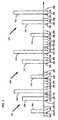
- two access channel signals 10 and 12are despread at a receiver (not shown), which produces respective correlation spikes 14 and 16.
- Signal 12arrives shortly after signal 10 because, for example, the transmitter from which signal 12 emanates is further from the receiver than the transmitter from which signal 10 emanates.
- Signals 10 and 12may be direct sequence spread spectrum signals of a CDMA cellular telephone system (not shown).
- the transmittersare access channel transmitters of mobile stations and the receiver is an access channel receiver of a base station.
- the receivermay be unable to distinguish between signals 10 and 12. This may be true in Fig. 1 when, for example, the two mobile stations are less than 120 meters (m) apart and the access channel has a chip rate of 1.2288 megahertz (MHz). A collision is said to occur when the receiver cannot distinguish the signals.
- Each mobile stationuses "PN randomization" to reduce the probability of a collision between its transmitted signal and those of other mobile stations on the same access channel.
- PN randomizationa first mobile station transmitter may delay signal 10 to the location of delayed signal 18 and a second mobile station transmitter may delay signal 12 to the location of delayed signal 20.
- a hash functionis preferred for generating the delay because it enables the base station to determine the delay used by the mobile station. The base station can then calculate the range to the mobile station by measuring the total delay experienced by a message in arriving at the mobile station and subtracting the added PN randomization delay.
- Equation 1uses the electronic serial number (ESN) associated with the mobile station to produce the delay.
- the hash functionproduces a delay, RN, in the range of 0 to 512 chips of the PN code sequence generator that modulates the signal. Note that the maximum delay is much less than the delay provided by the other randomizations discussed below.
- the base stationmay provide a range index, PROBE_PN_RAN, to the mobile station during system initialization or at other times.
- the delay range, Ris defined as 2 PROBE_PN_RAN .
- RNR x ((40503 x (L ⁇ H ⁇ D)) mod 2 16 ) / 2 16 where:
- two access channel signals 22 and 24are despread by a receiver correlator (not shown), which produces respective correlation spikes 26 and 28.
- signal 24arrives shortly after signal 22.
- Signals 22 and 24are delayed using the method described above.
- the presence of multipathcreates multipath correlation spikes 30 and 32 in signals 22 and 24 respectively.
- a diversity base station receivercould combine spikes 26 and 30 to improve reception of signal 22.
- the receivermay not be able to distinguish signal 22 from signal 24 if multipath correlation spike 32 is received within one chip of correlation spike 26 or if multipath correlation spike 30 is received within one chip of correlation spike 28.
- the receivercannot determine which spike is associated with which signal and therefore cannot combine them. However, if a PN randomization delay of one or more chips is added, for example, to signal 24 then signal 24 will be shifted towards the right in Fig. 2 and correlation spike 32 will not interfere with correlation spike 26.
- a base station diversity receivercould then assume that multipath components occurring close to one another, such as spikes 26 and 30, are associated with the same transmitted signal 22 and could therefore be combined. Similarly, a base station receiver could assume that spikes 28 and 32 are associated with signal 24 and combine them. Such assumptions are valid because multipath delays are typically less than one chip.
- two access channel signals 34 and 36are despread by two separate receiver correlators (not shown).
- Two mobile station transmitters(not shown) use "channel randomization" to modulate their respective signals 34 and 36 respectively with different PN codes, thereby requiring the base station receiver to use different correlators to demodulate them.
- signals 34 and 36share the same frequency band, they are said to occupy different access channels because they are modulated using different PN codes.
- the receiverdespreads signal 34 using the PN code corresponding to a first access channel and produces correlation spike 38, but signal 36 appears as noise to the receiver. This property, which allows a receiver to distinguish between signals 34 and 36 even in the presence of multipath, is well-known in spread spectrum communications. For each access channel that a base station receiver can receive simultaneously with other access channels, the base station must have a receiver that uses a PN code corresponding to that access channel.
- the transmitterrandomly selects an access channel from a predetermined range, ACC_CHAN.
- the base stationmay provide this ACC_CHAN to the mobile station during system initialization or at other times during operation.
- ACC_CHANa predetermined range
- the number of access channels from which a mobile station may chooseis limited by hardware considerations and system throughput, a maximum of 32 is preferred.
- a mobile station processor 100executes the steps shown in Fig. 6a beginning at step 102 in an attempt to communicate with a base station (not shown).
- the processmay be initiated whenever the mobile station (not shown) must send information to the base station.
- a usermay initiate a telephone call, which must be routed to the base station.
- the mobile stationattempts to communicate by transmitting one or more "access probes" 104, 106, 108, 110, 112, 114, 116, 118 and 120 to the base station.
- An access probeconsists of one message and has a maximum duration of one "slot."
- a slotis a predetermined interval of system time to which the base stations and mobile stations are synchronized in the CDMA cellular telephone system described above.
- the actual slot lengthis not critical, for purposes of comparing the duration and randomization of access probes to PN randomization, discussed above, it may be on the order of 60 ms. Thus, the PN randomization delay is a very small fraction of a slot.
- access probe sequence 122consists of access probes 104, 106, and 108
- access probe sequence 124consists of access probes 110, 112, and 114
- access probe sequence 126consists of access probes 116,118, and 120.
- initiation signal 128,which is provided to processor 100.
- processor 100initializes a probe count, PROBE, to zero and an access probe sequence count, SEQ, to zero.
- processor 100computes the hash function described above to obtain the PN randomization delay, RN.
- Processor 100provides delay signal 134, which corresponds to RN, to timing generator 136.
- Processor 100provides the message data 138 to an encoder 140, which encodes it as described in the above-referenced U.S. Patents.
- the encoded message data 142is modulated with a PN long code 144, which is generated by a PN long code sequence generator 146.
- timing generator 136provides timing signals 156, 158, and 160 to these elements, which ultimately delays the transmitted signal 164.
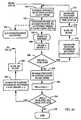
- processor 100determines whether the mobile station is attempting to respond to a communication from the base station or whether it is attempting to initiate a request for communication with the base station.
- a call initiated by a useris an example of a request attempt rather than a response attempt. If, as in Fig. 4, a request attempt is required, processor 100 proceeds to step 166. However, if a response attempt were required, the mobile station would perform a backoff randomization at step 168. In a backoff randomization, processor 100 generates a random number, RS, in the range of 0 to BKOFF+1, where BKOFF is a predetermined parameter. Then, at step 170 processor 100 would wait RS slots before proceeding to step 166. Processor 100 can count the slots to delay because it receives a slot count signal 172 from timing generator 136.
- processor 100performs the same request/response test discussed above. If a request attempt is required, processor 100 performs a persistence test, which introduces a random delay of one or more slots between successive access probe sequences. In the persistence test, processor 100 generates a random probability, RP, at the beginning of a slot at step 174. A predetermined parameter, P, represents the probability that the next access probe sequence will be performed. At step 176, processor 100 compares P to RP. If RP is less than P, the persistence test passes and processor 100 proceeds to step 178. If the persistence test fails, processor 100 repeats the test immediately before the beginning of the next slot.
- RPrandom probability
- Prepresents the probability that the next access probe sequence will be performed.
- processor 100compares P to RP. If RP is less than P, the persistence test passes and processor 100 proceeds to step 178. If the persistence test fails, processor 100 repeats the test immediately before the beginning of the next slot.
- processor 100determines that a response attempt is required rather than a request attempt at step 166, it proceeds to step 178.
- the persistence testis not necessary during response attempts because, unlike request attempts, the base station can schedule its communications requiring responses such that multiple mobile stations are not likely to respond simultaneously.
- processor 100begins step 174 at the beginning of a slot at time 180. Because the mobile station is attempting a request, it performs the persistence test. The test fails and is performed again immediately before the beginning of the slot at time 182. On this second attempt, the test passes and processor 100 proceeds to step 178.
- Processor 100performs a channel randomization at step 178. It generates a random number RA in the range from zero to ACC_CHAN, which is a predetermined parameter representing the maximum number of access channels. RA corresponds to the access channel on which access probe sequence 122 will be transmitted. Processor 100 provides access channel selection signal 183 to PN code sequence generator 146.
- processor 100initializes transmit power signal 186 to a predetermined initial level, INIT_PWR, which is provided to the power transmitter 188 in Fig. 5.
- INIT_PWRa predetermined initial level
- processor 100it is important to minimize the level of background noise, which is determined largely by the combined signals of many transmitters. A low level of background noise enables a receiver to more easily extract the desired spread-spectrum signal from the noise.
- the present inventionminimizes the power at which each mobile station transmits.
- INIT_PWRis set to a value that is below the level typically required for the base station to receive the message.
- Processor 100preferably estimates INIT_PWR using measured power levels of signals previously or currently received from the base station. Although the receiver portion of the mobile station is not shown, it is described in one or more of the above-referenced U.S. Patents.
- processor 100disables the system access state timer (not shown), which may be used to provide processor 100 with an indication that the mobile station has not received a message it is expecting from the base station within a predetermined timeout period. Such a timer must be disabled during access attempts.
- the messageis transmitted in access probe 104 on the selected access channel, RA.
- the PN randomizationfurther delays the beginning of access probe 104 to time 194, which occurs RN chips after time 182. This delay, which is much less than a 60 ms slot, is greatly exaggerated in Fig. 4 for the purpose of clarity.
- the height of access probe 104represents its relative power level.
- processor 100starts an internal acknowledgment timeout timer, TA.
- a predetermined timeout parameter, ACC_TMOindicates the length of time that processor 100 must wait for an acknowledgment to probe 104.
- processor 100If processor 100 receives an acknowledgment signal 198 within the timeout period, it proceeds to step 200 and ceases the access channel request attempt. It may then perform other actions that are not the subject of the present invention.
- processor 100proceeds to step 202.
- timer TAexpires at time 204.
- processor 100increments PROBE, the value of its internal probe counter.
- processor 100compares PROBE to NUM_STEP, which is a predetermined parameter that indicates the number of access probes to be performed in each access probe sequence if no acknowledgment is received.
- NUM_STEPis three because access probe sequence 122 consists of three access probes 104, 106, and 108. Therefore, processor 100 proceeds to step 210.
- processor 100begins a probe backoff randomization.
- a probe backoff randomizationis similar to the backoff randomization described above, the difference being that probe backoff randomization is performed between successive access probes of an access probe sequence, while backoff randomization is performed before each access probe sequence.
- the value of PROBE_BKOFFmay or may not be equal to that of BKOFF.
- processor 100generates a random number, RT, in the range from zero to PROBE_BKOFF+1, which is a predetermined parameter.
- processor 100waits RT slots. For example, in Fig. 4 RT is "2" and processor 100 waits two slots until the slot beginning at time 214.
- processor 100changes transmit power signal 186 to a number that causes power transmitter 188 to increase transmit power by a number of decibels (dB) equal to 0.5 times PWR_STEP, which is a predetermined parameter.
- Processor 100then proceeds to step 190 and transmits access probe 106 at an increased power level on the same access channel, RA, at time 218, which is RN chips after the beginning of the slot at time 214.
- Processor 100does not receive an acknowledgment within the timeout period from time 220 to time 222. It generates a probe backoff, RT, of "1" and waits one slot at step 212 until the slot beginning at time 224.
- Access probe 108is transmitted at a further increased power level on the same access channel, RA, at time 226, which is RN chips after the beginning of the slot at time 224. Because no acknowledgment has been received from the base station by the end of the timeout period at time 230 and NUM_STEP probes have been transmitted, processor 100 proceeds to step 232.
- processor 100enables the system access state timer (not shown) and proceeds to step 234. Having completed transmission of access probe sequence 122, processor 100 increments SEQ, the value of its internal access probe sequence counter. At step 236, processor 100 compares SEQ to MAX_REQ_SEQ or MAX_RSP_SEQ, the former being a predetermined parameter for indicating the maximum number of access probe sequences to perform before aborting a request attempt and the latter being a predetermined parameter for indicating the maximum number of access probe sequences to perform before aborting a response attempt. If one of these maxima is reached, processor 100 proceeds to step 238. It may then perform other actions that are not the subject of the present invention.
- processor 100proceeds to step 240, where it performs a backoff randomization as described above with reference to steps 168 and 170. For example, in Fig. 4 processor 100 at time 230 generates a random number RS of "1" and waits one slot at step 242 until the slot beginning at time 248. Processor 100 then returns to step 166 (Fig 6a) to begin access probe sequence 124.
- Processor 100performs the steps for producing access probe sequence 124 in a like manner to those for producing access probe sequence 122. If, as in the present example, a request attempt is required, processor 100 performs a persistence test at step 174 immediately before the slot beginning at time 248. The test fails and is repeated immediately before the slot beginning at time 250. This second test fails and is repeated immediately before the slot beginning at time 252. The third test passes and processor 100 proceeds to step 178.
- Processor 100performs a channel randomization at step 178. Because processor 100 randomly selects an access channel at the beginning of each access probe sequence, the access channel on which access probe sequence 124 is to be transmitted may not be the same as that on which access probe sequence 122 was transmitted.
- processor 100initializes transmit power signal 186, and at step 190 (Fig. 6b) processor 100 disables the system access state timer.
- step 192the message is transmitted in access probe 110, further delayed to time 254 from the slot beginning at time 252 by the PN randomization.
- Processor 100proceeds to step 202 after the timeout period has elapsed at time 258 without having received acknowledgment signal 198.
- processor 100produces a random number RT of "3" and processor 100 waits three slots at step 212 until the slot beginning at time 260.
- processor 100increases the power of signal 164 and transmits access probe 112 at the increased power level at time 262, which is RN chips after the beginning of the slot at time 260.
- Processor 100proceeds through the above steps a third time because it does not receive acknowledgment signal before the timeout period expires at time 266. It generates a probe backoff of two slots and waits until time 268. Access probe 114 is transmitted at time 270, which is RN chips after time 268. Transmission of access probe 114 without an acknowledgment by the timeout at time 274 completes access probe sequence 124, and processor 100 increments SEQ at step 234. Processor 100 then generates a backoff randomization of "1" at step 240. Processor 100 waits one slot at step 242 until the slot beginning at time 276. Processor 100 then returns to step 166 to begin access probe sequence 126.
- processor 100performs a persistence test at step 174.
- the persistence testfails three times before passing before the slot beginning at time 284.
- access probe sequence 126access probe 116 is transmitted at time 286, access probe 118 is transmitted at time 294, and access probe 120 is transmitted at time 302 as described above.
- processor 100After the mobile station transmits access probe 304 and before the timeout timer has reached ACC_TMO, processor 100 receives acknowledgment signal 198 from the base station at time 306. In response to acknowledgment signal 198, processor 100 proceeds to step 200 and ceases the request attempt.
- Fig. 4illustrates a request attempt
- a response attemptwould be similar.
- no persistence testwould be performed before access probe 104.
- the backoff randomization at steps 168 and 170would produce a backoff delay before access probe 104.
- no persistence testswould be performed between access probe sequences 122 and 124 and between sequences 124 and 126.
Landscapes
- Engineering & Computer Science (AREA)
- Computer Networks & Wireless Communication (AREA)
- Signal Processing (AREA)
- Mobile Radio Communication Systems (AREA)
- Small-Scale Networks (AREA)
Abstract
Description
Claims (85)
- An apparatus for reducing collisions between transmitted messages in acommunications network, wherein said message is a direct spread spectrumsignal spread using a PN code sequence on a channel with a chip rate, saidapparatus having a unique identification code, said apparatus comprising:processor means (100) for providing said a message; a timinggenerator (136) for providing a delay time in response to said uniqueidentification code; wherein the delay time is greater than or equal to onechip, but is less than the length of the message itself:an encoder (140) for delaying said message by said delay time; anda transmitter (188) for transmitting, at a time determined inaccordance with said unique identification code, said delayed message to areceiver.
- The apparatus described in claim 1, wherein:said transmitted delayed message isspread using a PN code sequence having said chip rate;
- The apparatus described in claim 1,
wherein said processor means (100) further provides at least onerandom number;
the apparatus further comprising a PN code sequence generator(146) for randomly selecting a PN code sequence from a predetermined setof PN code sequences in response to a random number received from saidprocessor means (100); and
wherein said transmitter (188) is for transmitting said delayedmessage to a receiver, said transmitted delayed message being a directsequence spread spectrum signal spread using said PN code sequence having a chip rate wherein said delay time is equal to or greater than onechip. - The apparatus described in claim 3, wherein said processor means (100) isfurther for receiving an acknowledgement indication in response to anacknowledgement, for measuring the time between transmission of saidmessage and said acknowledgement indication and for providing a timeoutsignal if said time exceeds a predetermined timeout parameter, and forproviding an additional message in response to said timeout signal.
- The apparatus described in claim 4 wherein said processor means (100) is furtherfor counting said successive messages to provide a probe count, said probecount being reset upon reaching a predetermined maximum probe count; andfor providing a power level signal to said transmitter (188) for increasing tilepower of each said successive message, said power being a predeterminedminimum when said probe count is reset.
- The apparatus described in claim 5, wherein said processor means (100) increasessaid power of each said successive message by a predetermined increment.
- The apparatus described in claim 6, wherein:said processor means (100) inserts a backoff delay between saidsuccessive messages in response to said timeout signal, said backoff delaycorresponding to a second random number.
- The apparatus described in claim 7, wherein: said processor means (100) isinhibited from providing said message when said probe counter is reset anda third random number is within a predetermined persistence range.
- A method for reducing collisions between messages in a communicationsnetwork having a plurality of transmitters and at least one receiver, each ofsaid transmitters having a unique identification code, wherein said message is a direct spread spectrum signal spread using a PN code sequence on achannel with a chip rate, said method comprising the repeated steps of:generating said message;delaying said message by a delay time corresponding to saididentification code, wherein the delay time is greater than or equal to onechip but is less than the length of the message itself; andtransmitting said delayed message at a time determined inaccordance with said unique identification code.
- The method for reducing collisions between messages described in claim 9,wherein:said transmitted delayed message is a direct sequence spreadspectrum signal spread using a PN code sequence having said chip rate.
- The method for reducing collisions between messages described in claim 9comprising the further steps of:randomly selecting a PN code sequence from a predetermined set ofPN code sequences;modulating said delayed message with said PN code sequencebefore transmitting said delayed message.
- The method for reducing collisions between messages described in claim 11,further comprising the step of:monitoring an acknowledgement signal from said receiver during apredetermined timeout period.
- The method for reducing collisions between messages described in claim 12,further comprising, before said transmitting step, the steps of:generating a first random number;selecting a backoff time period from a predetermined range inresponse to said first random number; andwaiting said backoff time period.
- The method for reducing collisions between messages described in claim 13,further comprising the steps of:increasing said power level by a predetermined power increment;incrementing a probe count;comparing said probe count to a predetermined probe sequencelength; andsetting said power level to a predetermined initial value when saidprobe count equals said predetermined probe sequence length.
- The method for reducing collisions between messages described in claim 14,further comprising the steps of:repeatedly generating a second random number and comparing it toa predetermined persistence parameter until said second random number iswithin a range corresponding to said predetermined persistence parameter.
- The apparatus of claim 1, wherein said apparatus is employed in acommunication device and is for reducing collisions between messages ofsaid communications device and other communication devices in saidcommunications network,
wherein said processor means (100) is further for providing a timingsignal in accordance with said unique identification code, and for providingsaid message in response to said timing signal; and
wherein said transmitter means (188) transmits said message at atime determined in accordance with said unique identification code. - The apparatus of claim 16 wherein said encoder (140) encodes saidmessage for transmission according to a predetermined coding format.
- The apparatus of claim 16 wherein said processor means (100) is further forencoding said message for transmission according to a predeterminedcoding format.
- The apparatus of claim 18 wherein said processor means (100) is further forgenerating a first random number within a backoff delay range of numbersand for providing a second timing signal responsive to said first randomnumber and said delay signal and for further delaying the provision of saidmessage responsive to said second timing signal.
- The apparatus of claim 19 wherein said processor means (100) is further forgenerating at least one second random number within a random probabilityrange of numbers, comparing said second random number with apredetermined parameter, inhibiting the provision of said message if saidsecond random number is less than said predetermined parameter, andrepeating said steps of generating said second random number, comparingsaid second random number with said predetermined parameter, andinhibiting the provision of said message until one of said at least one secondrandom number exceeds said predetermined parameter.
- The apparatus of claim 20 wherein said processor means (100) is further forrandomly selecting a channel number from a set of access channel numbers,providing said selected channel number, and providing a PN code inaccordance with said channel number, said apparatus further comprising:spreading means (152) for receiving said PN code and directsequence spreading said encoded message in accordance with said PNcode.
- The apparatus of claim 21 wherein said processor means (100) is further forreceiving a message acknowledged signal, providing a retransmission signalif said message acknowledged signal is not received within a predeterminedtime duration, generating at least one additional random number within aprobe backoff range of numbers responsive to said retransmission signal, providing at least one additional timing signal in accordance with said at leastone additional random number, and providing at least one additionalmessage responsive to said at least one additional timing signal, repeatingsaid steps of generating at least one additional random number, providingsaid at least one additional timing signal, and providing said at least oneadditional message until said message acknowledged signal is received, andmaintaining a probe count equal to the number of said at least one additionalmessage provisions.
- The apparatus of claim 22 wherein said processor means (100) is further forproviding a transmission power signal (186) in accordance with said probecount; and wherein said transmitter (188) is responsive to said power signal(186).
- The apparatus of claim 23 wherein said processor means (100) is further forresetting said probe count when probe count is equal to a predeterminedprobe sequence number.
- The apparatus of claim 24 wherein said processor means (100) is further forgenerating a third random number from a backoff range of numbers,providing a sequence message responsive to said third random number.
- The apparatus of claim 25 wherein said processor means (100) is further forrandomly selecting a second channel number from a second set of accesschannel numbers, providing a PN code in accordance with said secondchannel number; and wherein said spreading means is further for receivingsaid PN code and direct sequence spreading said sequence message inaccordance with said PN code.
- The apparatus of claim 20 wherein said processor means (100) is further forreceiving a message acknowledged signal (ACK), providing a retransmissionsignal if said message acknowledged signal is not received within apredetermined time duration from the time of said message transmission, generating at least one additional random number within a probe backoffrange of numbers responsive to said retransmission signal, providing at leastone additional timing signal in accordance with said at least one additionalrandom number, and providing at least one additional message responsive tosaid at least one additional timing signal, repeating said steps of generatingat least one additional random number, providing said at least one additionaltiming signal, and providing said at least one additional message until saidmessage acknowledged signal is received, and maintaining a probe countequal to the number of said at least one additional message provisions.
- The apparatus of claim 27 wherein said processor means (100) is further forproviding a transmission power signal (186) in accordance with said probecount; and wherein said transmitter (188) is responsive to said power signal.
- The apparatus of claim 28 wherein said processor means (100) is further forresetting said probe count when probe count is equal to a predeterminedprobe sequence number.
- The apparatus of claim 29 wherein said processor means (100) is further forgenerating a third random number from a backoff range of numbers,providing a sequence message responsive to said third random number.
- The apparatus of claim 1, wherein the apparatus is employed In acommunications device and is for reducing collisions between messages ofsaid communications device and other communication devices in saidcommunications network,
wherein said processor means (100) is also for providing a timingsignal in accordance with said unique identification code, and for providingsaid message in response to said timing signal,
wherein said processor means further includes means for generatinga first random number within a backoff delay range of numbers and meansfor providing a second timing signal responsive to said first random number and said timing signal and means for further delaying the provision of saidmessage in response to said second timing signal;
wherein said encoder (140) is for encoding said message fortransmission according to a predetermined coding format - The apparatus of claim 31 wherein said processor means (100) is further forgenerating at least one second random number within a random probabilityrange of numbers, comparing said second random number with apredetermined parameter, inhibiting the provision of said message if saidsecond random number is less than said predetermined parameter, andrepeating said steps of generating said second random number, comparingsaid second random number with said predetermined parameter, andinhibiting the provision of said message until one of said at least one secondrandom number exceeds said predetermined parameter.
- The apparatus of claim 32 wherein said processor means (100) is further forrandomly selecting a channel number from a set of access channel numbersand for providing said selected channel number, said apparatus furthercomprising:PN code generator means (146) for receiving said channel numberand providing a PN code in accordance with said channel number; andspreading means for receiving said PN code and direct sequence spreadingsaid encoded message in accordance with said PN code.
- The apparatus of claim 33 wherein said processor means (100) is further forreceiving a message acknowledged signal, providing a retransmission signalif said message acknowledged signal is not received within a predeterminedtime-duration from the time of said message transmission, generating at leastone additional random number within a probe backoff range of numbersresponsive to said retransmission signal, providing at least one additionaltiming signal in accordance with said at least one additional random number,and providing at least one additional message responsive to said at least one additional timing signal, repeating said steps of generating at least oneadditional random number, providing said at least one additional timingsignal, and providing said at least one additional message until said messageacknowledged signal is received, and maintaining a probe count equal to thenumber of said at least one additional message provisions.
- The apparatus of claim 34 wherein said processor means (100) is further forproviding a transmission power signal (186) in accordance with said probecount; and wherein said transmitter (188) is responsive to said power signal.
- The apparatus of claim 35 wherein said processor means (100) is further forresetting said probe count when probe count is equal to a predeterminedprobe sequence number.
- The apparatus of claim 36 wherein said processor means (100) is further forgenerating a third random number from a backoff range of numbers andproviding a sequence message responsive to said third random number.
- The apparatus of claim 37, wherein said processor means (100) is further forrandomly selecting a second channel number from a second set of accesschannel numbers;
wherein said PN code generator means (146) is further for receivingsaid channel number and providing a PN code in accordance with saidsecond channel number; and
wherein said spreading means (152) is further for receiving said PNcode and direct sequence spreading said sequence message in accordancewith said PN code. - The apparatus of claim 32 wherein said processor means (100) is further forreceiving a message acknowledged signal, providing a retransmission signalif said message acknowledged signal is not received within a predeterminedtime duration from the time of said message transmission, generating at leastone additional random number within a probe backoff range of numbers responsive to said retransmission signal, providing at least one additionaltiming signal in accordance with said at least one additional random number,and providing at least one additional message responsive to said at least oneadditional timing signal, repeating said steps of generating at least oneadditional random number, providing said at least one additional timingsignal, and providing said at least one additional message until said messageacknowledged signal is received, and maintaining a probe count equal to thenumber of said at least one additional message provisions.
- The apparatus of claim 39 wherein said processor means (100) is further forproviding a transmission power signal in accordance with said probe count;and wherein said transmitter is responsive to said power signal.
- The apparatus of claim 40 wherein said processor means (100) is further forresetting said probe count when probe count is equal to a predeterminedprobe sequence number.
- The apparatus of claim 41 wherein said processor means (100) is further forgenerating a third random number from a backoff range of numbers,providing a sequence message responsive to said third random number.
- The apparatus of claim 1, wherein said apparatus is a circuit for reducingcollisions between messages of a communications device with othercommunications devices in a communications network, said circuitcomprising:wherein said transmitter (188) has an input coupled to saidprocessor circuit second output.a processor circuit having an output for providing a timing signaldetermined in accordance with said unique identification code and having asecond output for providing said message responsive to said timing signal;and
- The apparatus of claim 43 wherein said processor circuit (100) is further for encodingsaid message for transmission according to a predetermined coding format.
- The apparatus of claim 1, wherein said apparatus is a circuit for reducingcollisions between messages of a communications device with othercommunications devices in a communications network, said circuitcomprising:a processor circuit having an output for providing a timing signaldetermined in accordance with said identification code and having means forencoding a message for transmission as an encoded message according toa predetermined coding format, said processor circuit further including asecond output for providing said encoded message responsive to said timingsignal and means for generating a first random number within a backoff delayrange of numbers and means for providing a second timing signal responsiveto said first random number and said timing signal and means for furtherdelaying the provision of said message responsive to said second timingsignal; anda transmitter (188) having an input coupled to said processor circuitsecond output.
- The apparatus of claim 45 wherein said processor circuit is further for generatingat least one second random number within a random probability range ofnumbers, comparing said second random number with a predeterminedparameter, inhibiting the provision of said message if said second randomnumber is less than said predetermined parameter, and repeating said stepsof generating said second random number, comparing said second randomnumber with said predetermined parameter, and inhibiting the provision ofsaid message until one of said at least one second random number exceedssaid predetermined parameter.
- The apparatus of claim 46 wherein said processor circuit is further for randomlyselecting a channel number from a set of access channel numbers, providingsaid selected channel number, and providing a PN code in accordance with said channel number, and said circuit further comprising a spreading circuitfor receiving said PN code and direct sequence spreading said encodedmessage in accordance with said PN code.
- The apparatus of claim 47 wherein said processor circuit is further for receiving amessage acknowledged signal, providing a retransmission signal if saidmessage acknowledged signal is not received within a predetermined timeduration from the time of said message transmission, generating at least oneadditional random number within a probe backoff range of numbersresponsive to said retransmission signal, providing at least one additionaltiming signal in accordance with said at least one additional random number,and providing at least one additional message responsive to said at least oneadditional timing signal, repeating said steps of generating at least oneadditional random number, providing said at least one additional timingsignal, and providing said at least one additional message until said messageacknowledged signal is received, and maintaining a probe count equal to thenumber of said at least one additional message provisions.
- The apparatus of claim 48 wherein said processor circuit is further for providing atransmission power signal (186) in accordance with said probe count; andwherein said transmitter (188) is responsive to said power signal.
- The apparatus of claim 49 wherein said processor circuit is further for resettingsaid probe count when probe count is equal to a predetermined probesequence number.
- The apparatus of claim 50 wherein said processor circuit is further for generatinga third random number from a backoff range of numbers, providing asequence message responsive to said third random number.
- The apparatus of claim 51 wherein said processor circuit is further for randomlyselecting a second channel number from a second set of access channelnumbers, providing a PN code in accordance with said second channel number, and wherein said spreading circuit is further for receiving said PNcode and direct sequence spreading said sequence message in accordancewith said PN code.
- The apparatus of claim 46 wherein said processor circuit (100) is further for receiving amessage acknowledged signal, providing a retransmission signal if saidmessage acknowledged signal is not received within a predetermined timeduration from the time of said message transmission, generating at least oneadditional random number within a probe backoff range of numbersresponsive to said retransmission signal, providing at least one additionaltiming signal in accordance with said at least one additional random number,and providing at least one additional message responsive to said at least oneadditional timing signal, repeating said steps of generating at least oneadditional random number, providing said at least one additional timingsignal, and providing said at least one additional message until said messageacknowledged signal is received, and maintaining a probe count equal to thenumber of said at least one additional message provisions.
- The apparatus of claim 53 wherein said processor circuit is further for providing atransmission power signal (186) in accordance with said probe count; andwherein said transmitter is responsive to said power signal.
- The apparatus of claim 54 wherein said processor circuit is further for resettingsaid probe count when probe count is equal to a predetermined probesequence number.
- The apparatus of claim 55 wherein said processor circuit is further for generatinga third random number from a backoff range of numbers, providing asequence message responsive to said third random number.
- The method of claim 9 wherein a time period is divided into slots ofpredetermined durations, wherein said generating a message comprisesand said method comprising the further steps of:(a) providing said message;(b) generating a random number (168, 240) from a first range of numbers;and(c) delaying (180, 240) said message by a number of said slots equal to saidrandom number.
- The method of claim 57 further comprising the steps of:(d) generating at least one additional second random number in accordancewith a predetermined probability distribution;(e) comparing said second random number against a predetermined randomprobability parameter;(f) inhibiting said provision of said message if said generated second randomnumber is less than said random probability parameter; and(g) repeating said steps (d)-(f) until said additional random number exceedssaid random probability parameter.
- The method of claim 58 further comprising the steps of:(h) generating a second random number from a second range of randomnumbers;(i) determining a PN code in accordance with said second random number;and(j) direct sequence spreading said message in accordance with said secondrandom number.
- The method of claim 59 further comprising the steps of:(k) transmitting said delayed message at an initial power level;(l) receiving a message acknowledged signal;(m) generating at least one second additional random number if messageacknowledged signal is not received within a time out time period duration;(n) providing at least one additional message;(o) delaying said additional message by a number of slots equal to saidsecond additional random number;(p) transmitting said message at an increased power level wherein saidincreased power level is determined as the power level of the previoustransmission plus a predetermined increase(q) repeating said steps (m)-(p) until a message acknowledged signal isreceived.
- The method of claim 60 further comprising the steps of:(r) counting the number of said transmitted additional messages;(s) resetting said count if said number of said transmitted additionalmessages equals a sequence count;(t) increment a sequence count;(u) generating a fourth random number from a fourth range of numbers if saidnumber of said transmitted additional messages equals a sequence count;(v) providing a second additional message if said number of said transmittedadditional messages equals a sequence count;(w) delaying said second additional message by a number slots equal to saidfourth random number; and(x) repeating steps (d)-(q) until said sequence count equals a predeterminedmaximum count.
- The apparatus of claim 1, wherein the apparatus is used in a spreadspectrum communications system in which a plurality of remote stationscommunicate messages to a base station, and wherein said apparatus ineach remote station is for reducing collisions between messages of saidremote stations,
wherein said processor means is for providing a timing signal,
wherein said timing signal is determined in accordance with said uniqueidentification code and for providing said message responsive to said timingsignal; said system further comprising:spreading means (152) for direct sequence spreading said message;and wherein said transmitter is for transmitting said direct sequence spreadmessage at a time determined in accordance with said unique identificationcode. - The apparatus of claim 62 wherein said processor means is further forencoding said message for transmission according to a predeterminedcoding format.
- The apparatus of claim 1, wherein the apparatus is used in a spreadspectrum communications system in which a plurality of remote stationscommunicate messages to a base station, wherein said apparatus is in eachremote station for reducing collisions between messages of said remotestations, said system comprising:processor means for providing a timing signal, wherein said timingsignal is determined in accordance with said unique identification code andfor providing said message responsive to said timing signal, said processormeans further including means for encoding said message for transmissionaccording to a predetermined coding format and means for generating a firstrandom number within a backoff delay range of numbers and means forproviding a second timing signal responsive to said first random number andsaid timing signal and means for further delaying the provision of saidmessage responsive to said second timing signal;spreading means (152) for direct sequence spreading said message;andand wherein said transmitter is for transmitting said direct sequence spreadmessage.
- The apparatus of claim 64 wherein said processor means is further forgenerating at least one second random number within a random probabilityrange of numbers, comparing said second random number with apredetermined parameter, inhibiting the provision of said message if saidsecond random number is less than said predetermined parameter, andrepeating said steps of generating said second random number, comparingsaid second random number with said predetermined parameter, andinhibiting the provision of said message until one of said at least one secondrandom number exceeds said predetermined parameter.
- The apparatus of claim 65 wherein said processor means is further forrandomly selecting a channel number from a set of access channel numbers,providing said selected channel number, and providing a PN code inaccordance with said channel number; and wherein said spreading means isresponsive to said PN code.
- The apparatus of claim 66 wherein said processor means is further forreceiving a message acknowledged signal, providing a retransmission signalif said message acknowledged signal is not received within a predeterminedtime duration from said transmission of direct sequence spread message,generating at least one additional random number within a probe backoffrange of numbers responsive to said retransmission signal, providing at leastone additional timing signal in accordance with said at least one additionalrandom number, and providing at least one additional message responsive tosaid at least one additional timing signal, repeating said steps of generatingat least one additional random number, providing said at least one additionaltiming signal, and providing said at least one additional message until saidmessage acknowledged signal is received, and maintaining a probe countequal to the number of said at least one additional message provisions.
- The apparatus of claim 67 wherein said processor means is further forproviding a transmission power signal in accordance with said probe count;and wherein said transmitter is responsive to said power signal.
- The apparatus of claim 68 wherein said processor means is further forresetting said probe count when probe count is equal to a predeterminedprobe sequence number.
- The apparatus of claim 69 wherein said processor means is further forgenerating a third random number from a backoff range of numbers,providing a sequence message responsive to said third random number.
- The apparatus of claim 70 wherein said processor means is further forrandomly selecting a second channel number from a second set of accesschannel numbers, providing a PN code in accordance with said secondchannel number; and
wherein said spreading means is further for receiving said PN codeand direct sequence spreading said sequence message in accordance withsaid PN code. - The apparatus of claim 1, wherein the apparatus is used in a spreadspectrum communications system in which a plurality of remote stations eachhaving said unique identification code communicate messages to a basestation, said apparatus being in each remote station for reducing collisionsbetween messages of said remote stations,
wherein said processor means (100) is for determining a delay value inaccordance with said unique identification code and having an output forproviding said message responsive to said delay value; and
wherein said transmitter (188) has an input coupled to said processor(100) second output and an output for transmitting said message at a timedetermined in accordance with said unique identification code. - The apparatus of claim 72 further comprising an encoder (140) disposedbetween said processor means (100) and said transmitter (188) having an inputcoupled to said processor output and having an output coupled to saidtransmitter input.
- The apparatus of claim 73 further comprising a spreading circuit (152)disposed between said encoder (140) and said transmitter (188) having aninput coupled to said encoder (140) output and an output coupled to saidtransmitter input.
- The apparatus of claim 1, wherein the apparatus is used in a spreadspectrum communications system in which a plurality of remote stations eachhaving said unique identification code communicate messages to a base station, said apparatus being in each remote station for reducing collisionsbetween messages of said remote stations,
wherein said processor means (100) for determining a delay value inaccordance with said unique identification code and having an output forproviding said message responsive to said delay value, said processorfurther comprising a second output for providing a PN code;
wherein said encoder (140) has an input coupled to said processoroutput and having an output;
a spreading circuit (152) having an input coupled to said encoderoutput, a second input coupled to said processor second output and anoutput; and
wherein said transmitter (188) having an input coupled to saidspreading circuit output and an output for transmitting said message. - The apparatus of claim 75 further wherein said processor means further has asecond input for receiving a message acknowledged signal.
- The apparatus of claim 76 wherein said processor means further has a third outputfor providing a delay signal indicative of said delay value.
- The apparatus of claim 77 wherein said encoder further has a second inputcoupled to said third processor output.
- The apparatus of claim 78 further comprising a PN sequence generator (146)disposed between said processor means (100) and said spreading circuit having aninput coupled to said processor second output and an output coupled to saidspreading circuit second input.
- The apparatus of claim 79 wherein said PN sequence generator further has asecond input coupled to said processor third output.
- The apparatus of claim 80 further comprising timing generator (136) disposedbetween said processor means (100) and said encoder (140) having an input coupled to said processor third output and an output coupled to said encodersecond input.
- The apparatus of claim 81 wherein said timing generator (136) is furtherdisposed between said processor means (100) and said PN sequence generator(146) having an input coupled to said processor third output and an outputcoupled to said PN sequence generator second input.
- The apparatus of claim 82 further comprising an antenna (164) coupledhaving an input coupled to said transmitter output.
- The apparatus of claim 83 wherein said processor means (100) further has a secondinput for receiving a call initiate signal.
- The apparatus of claim 80 wherein said processor means (100) comprises amicroprocessor (100) and a timing generator (136).
Priority Applications (6)
| Application Number | Priority Date | Filing Date | Title |
|---|---|---|---|
| EP05014772AEP1583309B1 (en) | 1992-03-05 | 1993-03-04 | Apparatus and method for reducing message collision between mobile stations simultaneously accessing a base station in a CDMA cellular communications system |
| EP09002947AEP2058994B1 (en) | 1992-03-05 | 1993-03-04 | Apparatus and method for reducing message collision between mobile stations simultaneously accessing a base station in a CDMA cellular communications system |
| EP07024991AEP1901513A3 (en) | 1992-03-05 | 1993-03-04 | Apparatus and method for reducing message collision between mobile stations simultaneously accessing a base station in a CDMA cellular communications system |
| EP06022961AEP1746795B1 (en) | 1992-03-05 | 1993-03-04 | Apparatus and method for reducing message collision between mobile stations simultaneously accessing a base station in a CDMA cellular communications system |
| EP06022962AEP1746796B1 (en) | 1992-03-05 | 1993-03-04 | Apparatus and method for reducing message collision between mobile stations simultaneously accessing a base station in a CDMA cellular communications system |
| EP10010904AEP2317718A1 (en) | 1992-03-05 | 1993-03-04 | Apparatus and method for reducing message collision between mobile stations simultaneously accessing a base station in a CDMA cellular communication system |
Applications Claiming Priority (3)
| Application Number | Priority Date | Filing Date | Title |
|---|---|---|---|
| US84715292A | 1992-03-05 | 1992-03-05 | |
| US847152 | 1992-03-05 | ||
| PCT/US1993/001982WO1993018601A1 (en) | 1992-03-05 | 1993-03-04 | Apparatus and method for reducing message collision between mobile stations simultaneously accessing a base station in a cdma cellular communications system |
Related Child Applications (2)
| Application Number | Title | Priority Date | Filing Date |
|---|---|---|---|
| EP05014772ADivisionEP1583309B1 (en) | 1992-03-05 | 1993-03-04 | Apparatus and method for reducing message collision between mobile stations simultaneously accessing a base station in a CDMA cellular communications system |
| EP05014772.7Division-Into | 2005-07-07 |
Publications (3)
| Publication Number | Publication Date |
|---|---|
| EP0629325A1 EP0629325A1 (en) | 1994-12-21 |
| EP0629325A4 EP0629325A4 (en) | 1998-04-08 |
| EP0629325B1true EP0629325B1 (en) | 2005-10-12 |
Family
ID=25299903
Family Applications (7)
| Application Number | Title | Priority Date | Filing Date |
|---|---|---|---|
| EP06022961AExpired - LifetimeEP1746795B1 (en) | 1992-03-05 | 1993-03-04 | Apparatus and method for reducing message collision between mobile stations simultaneously accessing a base station in a CDMA cellular communications system |
| EP06022962AExpired - LifetimeEP1746796B1 (en) | 1992-03-05 | 1993-03-04 | Apparatus and method for reducing message collision between mobile stations simultaneously accessing a base station in a CDMA cellular communications system |
| EP07024991AWithdrawnEP1901513A3 (en) | 1992-03-05 | 1993-03-04 | Apparatus and method for reducing message collision between mobile stations simultaneously accessing a base station in a CDMA cellular communications system |
| EP10010904AWithdrawnEP2317718A1 (en) | 1992-03-05 | 1993-03-04 | Apparatus and method for reducing message collision between mobile stations simultaneously accessing a base station in a CDMA cellular communication system |
| EP05014772AExpired - LifetimeEP1583309B1 (en) | 1992-03-05 | 1993-03-04 | Apparatus and method for reducing message collision between mobile stations simultaneously accessing a base station in a CDMA cellular communications system |
| EP93907229AExpired - LifetimeEP0629325B1 (en) | 1992-03-05 | 1993-03-04 | Apparatus and method for reducing message collision between mobile stations simultaneously accessing a base station in a cdma cellular communications system |
| EP09002947AExpired - LifetimeEP2058994B1 (en) | 1992-03-05 | 1993-03-04 | Apparatus and method for reducing message collision between mobile stations simultaneously accessing a base station in a CDMA cellular communications system |
Family Applications Before (5)
| Application Number | Title | Priority Date | Filing Date |
|---|---|---|---|
| EP06022961AExpired - LifetimeEP1746795B1 (en) | 1992-03-05 | 1993-03-04 | Apparatus and method for reducing message collision between mobile stations simultaneously accessing a base station in a CDMA cellular communications system |
| EP06022962AExpired - LifetimeEP1746796B1 (en) | 1992-03-05 | 1993-03-04 | Apparatus and method for reducing message collision between mobile stations simultaneously accessing a base station in a CDMA cellular communications system |
| EP07024991AWithdrawnEP1901513A3 (en) | 1992-03-05 | 1993-03-04 | Apparatus and method for reducing message collision between mobile stations simultaneously accessing a base station in a CDMA cellular communications system |
| EP10010904AWithdrawnEP2317718A1 (en) | 1992-03-05 | 1993-03-04 | Apparatus and method for reducing message collision between mobile stations simultaneously accessing a base station in a CDMA cellular communication system |
| EP05014772AExpired - LifetimeEP1583309B1 (en) | 1992-03-05 | 1993-03-04 | Apparatus and method for reducing message collision between mobile stations simultaneously accessing a base station in a CDMA cellular communications system |
Family Applications After (1)
| Application Number | Title | Priority Date | Filing Date |
|---|---|---|---|
| EP09002947AExpired - LifetimeEP2058994B1 (en) | 1992-03-05 | 1993-03-04 | Apparatus and method for reducing message collision between mobile stations simultaneously accessing a base station in a CDMA cellular communications system |
Country Status (22)
| Country | Link |
|---|---|
| US (6) | US5544196A (en) |
| EP (7) | EP1746795B1 (en) |
| JP (1) | JP3152353B2 (en) |
| KR (1) | KR100202745B1 (en) |
| CN (1) | CN1072863C (en) |
| AT (5) | ATE362263T1 (en) |
| AU (1) | AU677578B2 (en) |
| BG (1) | BG62022B1 (en) |
| BR (1) | BR9306032A (en) |
| CA (1) | CA2130667C (en) |
| DE (4) | DE69334205T2 (en) |
| DK (3) | DK2058994T3 (en) |
| ES (5) | ES2299133T3 (en) |
| FI (1) | FI114537B (en) |
| HU (1) | HU214413B (en) |
| IL (1) | IL104910A (en) |
| MX (1) | MX9301230A (en) |
| PT (2) | PT1583309E (en) |
| RU (1) | RU2171013C2 (en) |
| SK (1) | SK282136B6 (en) |
| WO (1) | WO1993018601A1 (en) |
| ZA (1) | ZA931077B (en) |
Families Citing this family (183)
| Publication number | Priority date | Publication date | Assignee | Title |
|---|---|---|---|---|
| AU8959191A (en) | 1990-10-23 | 1992-05-20 | Omnipoint Corporation | Method and apparatus for establishing spread spectrum communications |
| US5285469A (en) | 1991-06-03 | 1994-02-08 | Omnipoint Data Corporation | Spread spectrum wireless telephone system |
| ZA931077B (en)* | 1992-03-05 | 1994-01-04 | Qualcomm Inc | Apparatus and method for reducing message collision between mobile stations simultaneously accessing a base station in a cdma cellular communications system |
| EP0639899B2 (en)* | 1993-03-05 | 2008-02-27 | Ntt Mobile Communications Network Inc. | Random access communication method by use of cdma, and system for mobile stations which use the method |
| US5436941A (en)* | 1993-11-01 | 1995-07-25 | Omnipoint Corporation | Spread spectrum spectral density techniques |
| DE69536131D1 (en)* | 1994-02-09 | 2011-02-03 | Ntt Docomo Inc | Method and system for CDMA mobile communication |
| JP2655108B2 (en)* | 1994-12-12 | 1997-09-17 | 日本電気株式会社 | CDMA transceiver |
| DE19503209C1 (en)* | 1995-02-02 | 1996-10-02 | Becker Gmbh | Process for initializing a network with several master-capable, i.e. clock-capable network participants |
| US6356607B1 (en) | 1995-06-05 | 2002-03-12 | Omnipoint Corporation | Preamble code structure and detection method and apparatus |
| ZA965340B (en) | 1995-06-30 | 1997-01-27 | Interdigital Tech Corp | Code division multiple access (cdma) communication system |
| US6885652B1 (en) | 1995-06-30 | 2005-04-26 | Interdigital Technology Corporation | Code division multiple access (CDMA) communication system |
| US7123600B2 (en) | 1995-06-30 | 2006-10-17 | Interdigital Technology Corporation | Initial power control for spread-spectrum communications |
| US5841768A (en) | 1996-06-27 | 1998-11-24 | Interdigital Technology Corporation | Method of controlling initial power ramp-up in CDMA systems by using short codes |
| US7929498B2 (en) | 1995-06-30 | 2011-04-19 | Interdigital Technology Corporation | Adaptive forward power control and adaptive reverse power control for spread-spectrum communications |
| US7020111B2 (en) | 1996-06-27 | 2006-03-28 | Interdigital Technology Corporation | System for using rapid acquisition spreading codes for spread-spectrum communications |
| US6041046A (en)* | 1995-07-14 | 2000-03-21 | Omnipoint Corporation | Cyclic time hopping in time division multiple access communication system |
| JP3212238B2 (en) | 1995-08-10 | 2001-09-25 | 株式会社日立製作所 | Mobile communication system and mobile terminal device |
| DE69638236D1 (en)* | 1995-09-20 | 2010-09-23 | Nippon Telegraph & Telephone | Access method, mobile station and base station for CDMA mobile communication system |
| US5850525A (en)* | 1996-03-29 | 1998-12-15 | Advanced Micro Devices, Inc. | Method and apparatus for adding a randomized propagation delay interval to an interframe spacing in a station accessing an ethernet network |
| US5629929A (en)* | 1996-06-07 | 1997-05-13 | Motorola, Inc. | Apparatus for rapid interference cancellation and despreading of a CDMA waveform |
| US6021122A (en)* | 1996-06-07 | 2000-02-01 | Qualcomm Incorporated | Method and apparatus for performing idle handoff in a multiple access communication system |
| US6178164B1 (en)* | 1996-06-07 | 2001-01-23 | Qualcomm Incorporated | Method and apparatus for performing idle handoff in a multiple access communication system |
| JP3386098B2 (en)* | 1996-06-20 | 2003-03-10 | 株式会社エヌ・ティ・ティ・ドコモ | Signal transmission method in CDMA mobile communication system, mobile station apparatus and base station apparatus |
| AU6987896A (en)* | 1996-09-06 | 1998-03-26 | Brigitta Wagner | Wireless communications system using beam direction multiplexing |
| US6002664A (en)* | 1997-02-24 | 1999-12-14 | At&T Wireless Services Inc. | Method to gain access to a base station in a discrete multitone spread spectrum communications system |
| EP0990351B1 (en)* | 1997-06-17 | 2003-03-26 | Siemens Aktiengesellschaft | Method, mobile station and base station for transmitting signals |
| US20020051434A1 (en)* | 1997-10-23 | 2002-05-02 | Ozluturk Fatih M. | Method for using rapid acquisition spreading codes for spread-spectrum communications |
| KR100329186B1 (en)* | 1997-12-27 | 2002-09-04 | 주식회사 하이닉스반도체 | Reverse Call Channel Search Method of CDM Mobile Communication System |
| US6018547A (en)* | 1998-01-09 | 2000-01-25 | Bsd Broadband, N.V. | Method and apparatus for increasing spectral efficiency of CDMA systems using direct sequence spread spectrum signals |
| KR100326182B1 (en)* | 1998-03-23 | 2002-07-02 | 윤종용 | Method and apparatus for generating pseudo noise sequence in code division multiple access communication system |
| KR100381012B1 (en) | 1998-05-04 | 2003-08-19 | 한국전자통신연구원 | Random connection device for reverse common channel in cdma scheme and method therefor |
| US7123628B1 (en)* | 1998-05-06 | 2006-10-17 | Lg Electronics Inc. | Communication system with improved medium access control sub-layer |
| DE19821004C2 (en)* | 1998-05-11 | 2000-03-23 | Ericsson Telefon Ab L M | Sequence generator |
| US6674765B1 (en)* | 1998-05-22 | 2004-01-06 | Lucent Technologies Inc. | Methods and apparatus for random chip delay access priority in a communications system |
| US6104927A (en)* | 1998-05-28 | 2000-08-15 | Motorola, Inc. | Communication system, mobile station, and method for mobile station registration |
| US6366779B1 (en) | 1998-09-22 | 2002-04-02 | Qualcomm Incorporated | Method and apparatus for rapid assignment of a traffic channel in digital cellular communication systems |
| US7483699B2 (en)* | 1998-09-22 | 2009-01-27 | Qualcomm Incorporated | Overhead message update with decentralized control |
| US6252865B1 (en) | 1998-10-02 | 2001-06-26 | Qualcomm, Inc. | Methods and apparatuses for fast power control of signals transmitted on a multiple access channel |
| US6606313B1 (en) | 1998-10-05 | 2003-08-12 | Telefonaktiebolaget Lm Ericsson (Publ) | Random access in a mobile telecommunications system |
| US6256301B1 (en)* | 1998-10-15 | 2001-07-03 | Qualcomm Incorporated | Reservation multiple access |
| US6788937B1 (en)* | 1998-10-15 | 2004-09-07 | Qualcomm, Incorporated | Reservation multiple access |
| GB9823605D0 (en)* | 1998-10-29 | 1998-12-23 | Koninkl Philips Electronics Nv | Radio communication system |
| US6535736B1 (en) | 1998-12-11 | 2003-03-18 | Lucent Technologies Inc. | System and method for variably delaying access requests in wireless communications system |
| USRE47895E1 (en) | 1999-03-08 | 2020-03-03 | Ipcom Gmbh & Co. Kg | Method of allocating access rights to a telecommunications channel to subscriber stations of a telecommunications network and subscriber station |
| EP1511346B1 (en) | 1999-03-10 | 2017-11-22 | Thomson Licensing SAS | Random access burst transmission scheme and apparatus |
| US6574267B1 (en) | 1999-03-22 | 2003-06-03 | Golden Bridge Technology, Inc. | Rach ramp-up acknowledgement |
| US6169759B1 (en) | 1999-03-22 | 2001-01-02 | Golden Bridge Technology | Common packet channel |
| US6606341B1 (en)* | 1999-03-22 | 2003-08-12 | Golden Bridge Technology, Inc. | Common packet channel with firm handoff |
| MY128734A (en)* | 1999-03-22 | 2007-02-28 | Golden Bridge Tech Inc | Common packet channel |
| ES2620291T3 (en) | 1999-03-24 | 2017-06-28 | Qualcomm, Incorporated | Multiple Reserve Access |
| US6567420B1 (en)* | 1999-04-15 | 2003-05-20 | Qualcomm, Incorporated | Method and apparatus for high rate channel access control |
| US6947469B2 (en) | 1999-05-07 | 2005-09-20 | Intel Corporation | Method and Apparatus for wireless spread spectrum communication with preamble processing period |
| US6665272B1 (en) | 1999-09-30 | 2003-12-16 | Qualcomm Incorporated | System and method for persistence-vector-based modification of usage rates |
| US6643318B1 (en) | 1999-10-26 | 2003-11-04 | Golden Bridge Technology Incorporated | Hybrid DSMA/CDMA (digital sense multiple access/code division multiple access) method with collision resolution for packet communications |
| JP3525828B2 (en) | 1999-11-01 | 2004-05-10 | 株式会社日立製作所 | Location registration control method and mobile station device using the same |
| KR20010046952A (en)* | 1999-11-16 | 2001-06-15 | 배동만 | Anti-jamming method |
| US6480525B1 (en) | 1999-11-29 | 2002-11-12 | Golden Bridge Technology Inc. | Second level collision resolution for packet data communications |
| US6757319B1 (en) | 1999-11-29 | 2004-06-29 | Golden Bridge Technology Inc. | Closed loop power control for common downlink transport channels |
| JP3440048B2 (en)* | 2000-02-14 | 2003-08-25 | 松下電器産業株式会社 | Receiver and method for receiving pilot signal |
| AU760513B2 (en)* | 2000-02-16 | 2003-05-15 | Samsung Electronics Co., Ltd. | Apparatus and method for assigning a common packet channel in a CDMA communication system |
| DE60118254T2 (en)* | 2000-02-17 | 2006-08-17 | Samsung Electronics Co., Ltd., Suwon | Method for allocating a common packet channel in a CDMA communication channel |
| CN101534570A (en)* | 2000-02-23 | 2009-09-16 | Ipr特许公司 | Access probe acknowledgement with collision detection |
| WO2001093462A1 (en) | 2000-06-02 | 2001-12-06 | Samsung Electronics Co., Ltd. | Method for selecting rach in a cdma mobile communication system |
| US6778513B2 (en)* | 2000-09-29 | 2004-08-17 | Arraycomm, Inc. | Method and apparatus for separting multiple users in a shared-channel communication system |
| US6931030B1 (en)* | 2000-11-30 | 2005-08-16 | Arraycomm, Inc. | Training sequence with a random delay for a radio communications system |
| US7099671B2 (en)* | 2001-01-16 | 2006-08-29 | Texas Instruments Incorporated | Collaborative mechanism of enhanced coexistence of collocated wireless networks |
| US8605686B2 (en)* | 2001-02-12 | 2013-12-10 | Qualcomm Incorporated | Method and apparatus for power control in a wireless communication system |
| WO2002076134A1 (en)* | 2001-03-17 | 2002-09-26 | Koninklijke Philips Electronics N.V. | Network with common transmission channels |
| US7961616B2 (en) | 2001-06-07 | 2011-06-14 | Qualcomm Incorporated | Method and apparatus for congestion control in a wireless communication system |
| US20030039226A1 (en)* | 2001-08-24 | 2003-02-27 | Kwak Joseph A. | Physical layer automatic repeat request (ARQ) |
| IL160251A0 (en)* | 2001-08-24 | 2004-07-25 | Interdigital Tech Corp | Method for physical layer automatic repeat request for a base station |
| US20030073439A1 (en)* | 2001-10-17 | 2003-04-17 | Wenzel Peter W. | Home agent redundancy in a cellular system |
| EP1335537A1 (en)* | 2002-02-01 | 2003-08-13 | Thomson Licensing S.A. | Method for evaluating radio links in a communication network |
| DE10214117B4 (en)* | 2002-03-28 | 2005-06-23 | Siemens Ag | Adaptive modulation and other extensions of the physical layer in multiple access systems |
| US7110783B2 (en)* | 2002-04-17 | 2006-09-19 | Microsoft Corporation | Power efficient channel scheduling in a wireless network |
| JP3862074B2 (en)* | 2002-06-20 | 2006-12-27 | ソニー株式会社 | Data communication system, information processing apparatus and method, and program |
| GB0225903D0 (en)* | 2002-11-07 | 2002-12-11 | Siemens Ag | Method for uplink access transmissions in a radio communication system |
| US7811231B2 (en) | 2002-12-31 | 2010-10-12 | Abbott Diabetes Care Inc. | Continuous glucose monitoring system and methods of use |
| EP1435558A1 (en)* | 2003-01-02 | 2004-07-07 | Texas Instruments Incorporated | On-device random number generator |
| CN1275489C (en)* | 2003-03-18 | 2006-09-13 | 大唐移动通信设备有限公司 | Method for detecting multiple user's terminal random cutrin conflict |
| JP2004289717A (en)* | 2003-03-25 | 2004-10-14 | Mitsubishi Electric Corp | Random access control method, base station and terminal device |
| US7587287B2 (en) | 2003-04-04 | 2009-09-08 | Abbott Diabetes Care Inc. | Method and system for transferring analyte test data |
| US8066639B2 (en) | 2003-06-10 | 2011-11-29 | Abbott Diabetes Care Inc. | Glucose measuring device for use in personal area network |
| US7228134B2 (en)* | 2003-06-17 | 2007-06-05 | Lucent Technologies Inc. | Method of minimizing reverse channel interference caused by an abnormally high number of access attempts in a wireless communications system |
| US20050224596A1 (en)* | 2003-07-08 | 2005-10-13 | Panopoulos Peter J | Machine that is an automatic pesticide, insecticide, repellant, poison, air freshener, disinfectant or other type of spray delivery system |
| US7643412B1 (en)* | 2003-10-30 | 2010-01-05 | Nortel Networks Limited | Media proxy able to detect blocking |
| WO2005089103A2 (en) | 2004-02-17 | 2005-09-29 | Therasense, Inc. | Method and system for providing data communication in continuous glucose monitoring and management system |
| US7450541B2 (en) | 2004-03-09 | 2008-11-11 | Qualcomm Incorporated | Access channel with constrained arrival times |
| US7071866B2 (en)* | 2004-03-26 | 2006-07-04 | Northrop Grumman Corporation | 2-d range hopping spread spectrum encoder/decoder system for RF tags |
| KR100989314B1 (en)* | 2004-04-09 | 2010-10-25 | 삼성전자주식회사 | Display device |
| US8014377B2 (en)* | 2004-06-24 | 2011-09-06 | Nortel Networks Limited | Efficient location updates, paging and short bursts |
| EP2988563B1 (en) | 2004-10-15 | 2020-05-20 | Apple Inc. | Method and basis station for communication resource allocation |
| US9788771B2 (en) | 2006-10-23 | 2017-10-17 | Abbott Diabetes Care Inc. | Variable speed sensor insertion devices and methods of use |
| WO2006075770A1 (en)* | 2005-01-11 | 2006-07-20 | Nec Corporation | Base station apparatus, radio transmission system, radio base station program, and timing estimating method |
| US7742444B2 (en) | 2005-03-15 | 2010-06-22 | Qualcomm Incorporated | Multiple other sector information combining for power control in a wireless communication system |
| US20060209837A1 (en)* | 2005-03-16 | 2006-09-21 | Lee Jai Y | Method and apparatus for dynamically managing a retransmission persistence |
| WO2006117647A2 (en)* | 2005-05-02 | 2006-11-09 | Nokia Siemens Networks Oy | Implementing downlink code management for fractional dpch in timing conflict situations |
| US7729696B2 (en) | 2005-05-26 | 2010-06-01 | Motorola, Inc. | Method and apparatus for accessing a wireless communication network |
| US8750908B2 (en) | 2005-06-16 | 2014-06-10 | Qualcomm Incorporated | Quick paging channel with reduced probability of missed page |
| US9055552B2 (en) | 2005-06-16 | 2015-06-09 | Qualcomm Incorporated | Quick paging channel with reduced probability of missed page |
| WO2007003004A1 (en)* | 2005-07-01 | 2007-01-11 | Jeylan Kismet | Randomized sending of a message from a terminal |
| GB0513570D0 (en)* | 2005-07-04 | 2005-08-10 | Siemens Ag | Broadcast channel inter-cell interference avoidance scheme |
| US7542421B2 (en)* | 2005-09-09 | 2009-06-02 | Tropos Networks | Adaptive control of transmission power and data rates of transmission links between access nodes of a mesh network |
| US8379606B2 (en)* | 2005-09-22 | 2013-02-19 | Lg Electronics Inc. | Access probe randomization for wireless communication system |
| US20090207790A1 (en) | 2005-10-27 | 2009-08-20 | Qualcomm Incorporated | Method and apparatus for settingtuneawaystatus in an open state in wireless communication system |
| US20100150106A1 (en) | 2005-10-27 | 2010-06-17 | Qualcomm Incorporated | Method and apparatus for managing assignment during handoff in wireless communication systems |
| US7766829B2 (en) | 2005-11-04 | 2010-08-03 | Abbott Diabetes Care Inc. | Method and system for providing basal profile modification in analyte monitoring and management systems |
| DE102005060467A1 (en) | 2005-12-17 | 2007-06-21 | Bayer Cropscience Ag | carboxamides |
| US8412249B2 (en)* | 2005-12-20 | 2013-04-02 | Alcatel Lucent | Resource allocation based on interference mitigation in a wireless communication system |
| US7792075B2 (en) | 2006-01-05 | 2010-09-07 | Qualcomm Incorporated | Method and apparatus to perform persistence tests in a network |
| US8588115B2 (en) | 2006-01-11 | 2013-11-19 | Thomson Licensing | Apparatus for controlling channel switching in wireless networks |
| KR100732381B1 (en) | 2006-01-19 | 2007-06-27 | 주식회사 팬택 | Mobile communication terminal and method for fast access by controlling transmission power efficiently |
| US7813753B2 (en)* | 2006-02-27 | 2010-10-12 | Qualcomm Incorporated | Power control in communication systems |
| US8284793B2 (en)* | 2006-02-27 | 2012-10-09 | Qualcomm Incorporated | Backoff control for access probe transmission in communication systems |
| US7720499B2 (en)* | 2006-02-27 | 2010-05-18 | Tropos Networks, Inc. | Regulation of transmission power control in mitigate self interference by optimizing link transmission parameters in a wireless network |
| US8226891B2 (en) | 2006-03-31 | 2012-07-24 | Abbott Diabetes Care Inc. | Analyte monitoring devices and methods therefor |
| US7620438B2 (en) | 2006-03-31 | 2009-11-17 | Abbott Diabetes Care Inc. | Method and system for powering an electronic device |
| CN100499869C (en) | 2006-05-24 | 2009-06-10 | 华为技术有限公司 | Terminal equipment accessing method and system |
| DE102006030602A1 (en)* | 2006-07-03 | 2008-01-24 | Siemens Audiologische Technik Gmbh | Method for identifying hearing aids in the context of wireless programming |
| US8036186B2 (en)* | 2006-07-26 | 2011-10-11 | Tropos Networks, Inc. | Adaptively setting transmission power levels of nodes within a wireless mesh network |
| CN101132622B (en)* | 2006-08-20 | 2010-05-12 | 华为技术有限公司 | A Quality of Service Control Method for Random Access |
| EP2090126B1 (en)* | 2006-10-26 | 2012-03-14 | Nokia Corporation | Method for immediate access to a random access channel |
| DE602006005256D1 (en) | 2006-12-08 | 2009-04-02 | Research In Motion Ltd | Communication initiation in a push-to-talk over cellular (PoC) communication network |
| US20080139130A1 (en)* | 2006-12-08 | 2008-06-12 | Wen Zhao | System and method for initiating communication in a cellular network |
| US8565103B2 (en)* | 2006-12-12 | 2013-10-22 | Qualcomm Incorporated | Load determination in wireless networks |
| US7881738B2 (en)* | 2006-12-12 | 2011-02-01 | Qualcomm Incorporated | Estimation based approach to determine the retransmission timeout value for access probe retransmissions |
| US20080199894A1 (en) | 2007-02-15 | 2008-08-21 | Abbott Diabetes Care, Inc. | Device and method for automatic data acquisition and/or detection |
| US8123686B2 (en) | 2007-03-01 | 2012-02-28 | Abbott Diabetes Care Inc. | Method and apparatus for providing rolling data in communication systems |
| US8456301B2 (en) | 2007-05-08 | 2013-06-04 | Abbott Diabetes Care Inc. | Analyte monitoring system and methods |
| US8665091B2 (en) | 2007-05-08 | 2014-03-04 | Abbott Diabetes Care Inc. | Method and device for determining elapsed sensor life |
| US7928850B2 (en) | 2007-05-08 | 2011-04-19 | Abbott Diabetes Care Inc. | Analyte monitoring system and methods |
| US8461985B2 (en) | 2007-05-08 | 2013-06-11 | Abbott Diabetes Care Inc. | Analyte monitoring system and methods |
| US20080298436A1 (en)* | 2007-05-28 | 2008-12-04 | Telefonaktiebolaget L M Ericsson (Publ) | Random Access Collision Detection |
| AU2008265542B2 (en) | 2007-06-21 | 2014-07-24 | Abbott Diabetes Care Inc. | Health monitor |
| WO2008157820A1 (en) | 2007-06-21 | 2008-12-24 | Abbott Diabetes Care, Inc. | Health management devices and methods |
| US8098680B2 (en)* | 2007-08-14 | 2012-01-17 | Motorola Mobility, Inc. | Method and system for managing transmissions in a wireless communication network |
| US9648493B2 (en) | 2007-11-16 | 2017-05-09 | Qualcomm Incorporated | Using identifiers to establish communication |
| US20090132674A1 (en)* | 2007-11-16 | 2009-05-21 | Qualcomm Incorporated | Resolving node identifier confusion |
| US20090239550A1 (en) | 2008-03-18 | 2009-09-24 | Myers Theodore J | Random phase multiple access system with location tracking |
| US8477830B2 (en) | 2008-03-18 | 2013-07-02 | On-Ramp Wireless, Inc. | Light monitoring system using a random phase multiple access system |
| US7733945B2 (en) | 2008-03-18 | 2010-06-08 | On-Ramp Wireless, Inc. | Spread spectrum with doppler optimization |
| US20100195553A1 (en) | 2008-03-18 | 2010-08-05 | Myers Theodore J | Controlling power in a spread spectrum system |
| US8958460B2 (en) | 2008-03-18 | 2015-02-17 | On-Ramp Wireless, Inc. | Forward error correction media access control system |
| US7782926B2 (en)* | 2008-03-18 | 2010-08-24 | On-Ramp Wireless, Inc. | Random phase multiple access communication interface system and method |
| US8520721B2 (en) | 2008-03-18 | 2013-08-27 | On-Ramp Wireless, Inc. | RSSI measurement mechanism in the presence of pulsed jammers |
| US7773664B2 (en)* | 2008-03-18 | 2010-08-10 | On-Ramp Wireless, Inc. | Random phase multiple access system with meshing |
| US7826382B2 (en) | 2008-05-30 | 2010-11-02 | Abbott Diabetes Care Inc. | Close proximity communication device and methods |
| US9094880B2 (en)* | 2008-06-19 | 2015-07-28 | Qualcomm Incorporated | Access terminal assisted node identifier confusion resolution using a time gap |
| US20100008235A1 (en)* | 2008-07-11 | 2010-01-14 | Qualcomm Incorporated | Reporting and resolving conflicting use of a node identifier |
| US8743858B2 (en)* | 2008-07-15 | 2014-06-03 | Qualcomm Incorporated | Wireless communication systems with femto cells |
| US8989138B2 (en)* | 2008-07-15 | 2015-03-24 | Qualcomm Incorporated | Wireless communication systems with femto nodes |
| US8583117B2 (en)* | 2008-07-22 | 2013-11-12 | Qualcomm Incorporated | Wireless communication device that prioritizes access probe handling using a predetermined transmission delay |
| US8265683B2 (en)* | 2008-08-07 | 2012-09-11 | Qualcomm Incorporated | Two-tier random backoff and combined random backoff and transmit power control in wireless networks |
| US8886200B2 (en) | 2008-09-18 | 2014-11-11 | Qualcomm Incorporated | Using signal monitoring to resolve access point identifier ambiguity |
| US8428079B1 (en)* | 2008-09-24 | 2013-04-23 | Marvell International, Ltd | Systems and methods for discovering a wireless network in a peer-to-peer network |
| US9402544B2 (en) | 2009-02-03 | 2016-08-02 | Abbott Diabetes Care Inc. | Analyte sensor and apparatus for insertion of the sensor |
| US8363699B2 (en) | 2009-03-20 | 2013-01-29 | On-Ramp Wireless, Inc. | Random timing offset determination |
| WO2010127050A1 (en) | 2009-04-28 | 2010-11-04 | Abbott Diabetes Care Inc. | Error detection in critical repeating data in a wireless sensor system |
| US8368556B2 (en) | 2009-04-29 | 2013-02-05 | Abbott Diabetes Care Inc. | Method and system for providing data communication in continuous glucose monitoring and management system |
| WO2010138856A1 (en) | 2009-05-29 | 2010-12-02 | Abbott Diabetes Care Inc. | Medical device antenna systems having external antenna configurations |
| US8432801B2 (en) | 2009-07-31 | 2013-04-30 | Google Inc. | System and method for identifying multiple paths between network nodes |
| WO2011020824A2 (en)* | 2009-08-17 | 2011-02-24 | Nokia Siemens Networks Oy | Setting timing of communication network access point |
| EP3001194B1 (en) | 2009-08-31 | 2019-04-17 | Abbott Diabetes Care, Inc. | Medical devices and methods |
| US8993331B2 (en) | 2009-08-31 | 2015-03-31 | Abbott Diabetes Care Inc. | Analyte monitoring system and methods for managing power and noise |
| US9314195B2 (en) | 2009-08-31 | 2016-04-19 | Abbott Diabetes Care Inc. | Analyte signal processing device and methods |
| US9025572B2 (en) | 2009-09-03 | 2015-05-05 | Via Telecom Co., Ltd. | Apparatus, system, and method for access procedure enhancements |
| US8416641B2 (en)* | 2010-04-28 | 2013-04-09 | Semiconductor Components Industries, Llc | Acoustic distance measurement system having cross talk immunity |
| CN107019515B (en) | 2011-02-28 | 2021-02-26 | 雅培糖尿病护理公司 | Method of displaying sensor readings and analyte monitoring device and method of operating the same |
| US9036548B2 (en)* | 2011-08-15 | 2015-05-19 | Qualcomm Incorporated | Apparatuses and methods for controlling access to a radio access network |
| US8917705B2 (en)* | 2011-09-29 | 2014-12-23 | Qualcomm Incorporated | Collision reduction mechanisms for wireless communication networks |
| US9069536B2 (en) | 2011-10-31 | 2015-06-30 | Abbott Diabetes Care Inc. | Electronic devices having integrated reset systems and methods thereof |
| WO2013070794A2 (en) | 2011-11-07 | 2013-05-16 | Abbott Diabetes Care Inc. | Analyte monitoring device and methods |
| US9615316B2 (en)* | 2011-11-18 | 2017-04-04 | Qualcomm Incorporated | Methods and devices for facilitating modified cell reselection parameters and procedures when access terminals exhibit little or no mobility |
| EP2688334B1 (en) | 2012-07-17 | 2018-10-03 | LG Electronics Inc. | Method and apparatus for measuring data burst throughput in a wireless communications system |
| US9968306B2 (en) | 2012-09-17 | 2018-05-15 | Abbott Diabetes Care Inc. | Methods and apparatuses for providing adverse condition notification with enhanced wireless communication range in analyte monitoring systems |
| US10305640B2 (en)* | 2014-07-18 | 2019-05-28 | Samsung Electronics Co., Ltd. | Communication method of node in content centric network (CCN) and the node |
| KR102337119B1 (en)* | 2014-07-18 | 2021-12-09 | 삼성전자주식회사 | Communication method of node in content centric network(ccn) and node |
| US11727443B2 (en) | 2015-01-23 | 2023-08-15 | Bluezoo, Inc. | Mobile device detection and tracking |
| US20190026492A1 (en)* | 2017-07-22 | 2019-01-24 | Bluefox, Inc. | Protected pii of mobile device detection and tracking |
| US11151611B2 (en) | 2015-01-23 | 2021-10-19 | Bluezoo, Inc. | Mobile device detection and tracking |
| US11071478B2 (en) | 2017-01-23 | 2021-07-27 | Abbott Diabetes Care Inc. | Systems, devices and methods for analyte sensor insertion |
| CA3188510A1 (en) | 2020-08-31 | 2022-03-03 | Vivek S. RAO | Systems, devices, and methods for analyte sensor insertion |
| US20250168887A1 (en)* | 2023-11-16 | 2025-05-22 | Cisco Technology, Inc. | Adaptive code assignment to ambient power stations |
Family Cites Families (63)
| Publication number | Priority date | Publication date | Assignee | Title |
|---|---|---|---|---|
| JPS5325202B2 (en)* | 1972-08-29 | 1978-07-25 | ||
| JPS5318284B2 (en)* | 1972-12-26 | 1978-06-14 | ||
| US4320502A (en)* | 1978-02-22 | 1982-03-16 | International Business Machines Corp. | Distributed priority resolution system |
| US4400585A (en)* | 1979-11-30 | 1983-08-23 | Motorola, Inc. | Method and apparatus for automatically attempting to seize a radio channel in a multichannel communication system |
| JPS57115131A (en)* | 1981-01-07 | 1982-07-17 | Chiyuuichi Miyake | Production of fillet from fish |
| US4409592A (en)* | 1981-04-20 | 1983-10-11 | Hunt V Bruce | Multipoint packet data communication system using random access and collision detection techniques |
| GB2125654B (en)* | 1982-08-13 | 1986-01-29 | Hazeltine Corp | Intranetwork code division multiple access communication system |
| JPS60220635A (en)* | 1984-04-17 | 1985-11-05 | Clarion Co Ltd | Spread spectrum transmitter and receiver |
| US4653114A (en)* | 1984-06-21 | 1987-03-24 | General Instrument Corporation | Automatic terminal signal equalization |
| KR860001747B1 (en)* | 1984-11-26 | 1986-10-20 | 한국과학기술원 | Local area communication using code division multiplexing |
| GB8430003D0 (en)* | 1984-11-28 | 1985-01-09 | Plessey Co Plc | Subscriber line interface modem |
| US4675863A (en)* | 1985-03-20 | 1987-06-23 | International Mobile Machines Corp. | Subscriber RF telephone system for providing multiple speech and/or data signals simultaneously over either a single or a plurality of RF channels |
| US4653115A (en)* | 1985-03-27 | 1987-03-24 | Holcomb Jack N | Transmitter battery case |
| JPS61227442A (en) | 1985-03-30 | 1986-10-09 | Toshiba Electric Equip Corp | transmission device |
| JPS61227443A (en) | 1985-03-30 | 1986-10-09 | Toshiba Electric Equip Corp | Transmitter |
| JPS61227441A (en) | 1985-03-30 | 1986-10-09 | Toshiba Electric Equip Corp | Transmitter |
| JPH06101728B2 (en) | 1985-05-20 | 1994-12-12 | 沖電気工業株式会社 | Method of avoiding call collision of local network |
| AU593564B2 (en)* | 1985-07-24 | 1990-02-15 | Nec Corporation | Spread spectrum power line communications |
| JPS6269749A (en) | 1985-09-20 | 1987-03-31 | Sanyo Electric Co Ltd | Data transmission method |
| DE3607687A1 (en)* | 1986-03-08 | 1987-09-10 | Philips Patentverwaltung | METHOD AND CIRCUIT ARRANGEMENT FOR SWITCHING A RADIO CONNECTION INTO ANOTHER RADIO CELL OF A DIGITAL RADIO TRANSMISSION SYSTEM |
| JPH06101737B2 (en)* | 1986-04-14 | 1994-12-12 | 株式会社東芝 | Concentration distribution method |
| DK155265C (en)* | 1986-06-09 | 1989-07-31 | Rovsing As Christian | PROCEDURE FOR CONNECTING A DATA UNIT ON A SIGNAL PIPE AND APPARATUS FOR EXERCISING THE PROCEDURE |
| US4694467A (en) | 1986-07-03 | 1987-09-15 | Signatron, Inc. | Modem for use in multipath communication systems |
| SU1478368A1 (en) | 1987-08-10 | 1989-05-07 | Военная академия им.Ф.Э.Дзержинского | Multifrequency signal receiver |
| JP2583243B2 (en)* | 1987-09-18 | 1997-02-19 | 富士通株式会社 | Method for manufacturing MOS transistor |
| ZA882394B (en)* | 1988-04-05 | 1988-11-30 | American Cyanamid Co | Method for the depressing of hydrous,layered silicates |
| JPH0226176A (en)* | 1988-07-15 | 1990-01-29 | Mitsubishi Electric Corp | Facsimile communication method |
| US5056031A (en) | 1988-11-12 | 1991-10-08 | Kabushiki Kaisha Toyota Chuo Kenyusho | Apparatus for detecting the collision of moving objects |
| JPH02156751A (en)* | 1988-12-09 | 1990-06-15 | Mitsubishi Electric Corp | How to avoid LAN call collision |
| JP2531254B2 (en)* | 1989-01-18 | 1996-09-04 | 日本電気株式会社 | Line connection method for distributed wireless system |
| JPH02256331A (en)* | 1989-03-29 | 1990-10-17 | Sharp Corp | Radio communication system |
| US5680633A (en)* | 1990-01-18 | 1997-10-21 | Norand Corporation | Modular, portable data processing terminal for use in a radio frequency communication network |
| JPH02306460A (en) | 1989-05-19 | 1990-12-19 | Toshiba Corp | cassette loading device |
| GB8912768D0 (en)* | 1989-06-02 | 1989-07-19 | British Telecomm | Hybrid data communication system |
| JP2733110B2 (en)* | 1989-09-19 | 1998-03-30 | 日本電信電話株式会社 | Wireless signal transmission method |
| US5056109A (en)* | 1989-11-07 | 1991-10-08 | Qualcomm, Inc. | Method and apparatus for controlling transmission power in a cdma cellular mobile telephone system |
| US5109390A (en)* | 1989-11-07 | 1992-04-28 | Qualcomm Incorporated | Diversity receiver in a cdma cellular telephone system |
| US5204973A (en)* | 1989-11-17 | 1993-04-20 | Sanyo Electric Co., Ltd. | Receiver capable of quickly suppressing defective effect of multipath reflection interference |
| US5093841A (en)* | 1990-01-30 | 1992-03-03 | Nynex Corporation | Clock acquisition in a spread spectrum system |
| JPH03231523A (en) | 1990-02-07 | 1991-10-15 | Nippon Telegr & Teleph Corp <Ntt> | Mobile communication control system |
| US5077753A (en)* | 1990-04-09 | 1991-12-31 | Proxim, Inc. | Radio communication system using spread spectrum techniques |
| US5103459B1 (en)* | 1990-06-25 | 1999-07-06 | Qualcomm Inc | System and method for generating signal waveforms in a cdma cellular telephone system |
| IL100213A (en) | 1990-12-07 | 1995-03-30 | Qualcomm Inc | CDMA microcellular telephone system and distributed antenna system therefor |
| US5144668A (en) | 1991-01-25 | 1992-09-01 | Motorola, Inc. | Signal overlap detection in a communication system |
| US5204970A (en)* | 1991-01-31 | 1993-04-20 | Motorola, Inc. | Communication system capable of adjusting transmit power of a subscriber unit |
| CA2102502A1 (en)* | 1991-06-25 | 1992-12-26 | Michael J. Buchenhorner | Method and apparatus for establishing a communication link |
| US5243530A (en)* | 1991-07-26 | 1993-09-07 | The United States Of America As Represented By The Secretary Of The Navy | Stand alone multiple unit tracking system |
| US5278992A (en)* | 1991-11-08 | 1994-01-11 | Teknekron Communications Systems, Inc. | Method and apparatus for controlling transmission power of a remote unit communicating with a base unit over a common frequency channel |
| ZA931077B (en)* | 1992-03-05 | 1994-01-04 | Qualcomm Inc | Apparatus and method for reducing message collision between mobile stations simultaneously accessing a base station in a cdma cellular communications system |
| EP0565507A3 (en)* | 1992-04-10 | 1994-11-30 | Ericsson Ge Mobile Communicat | Power control for random access call set-up in a mobile telephone system |
| US5295153A (en)* | 1992-04-13 | 1994-03-15 | Telefonaktiebolaget L M Ericsson | CDMA frequency allocation |
| US5465399A (en)* | 1992-08-19 | 1995-11-07 | The Boeing Company | Apparatus and method for controlling transmitted power in a radio network |
| JP3181440B2 (en)* | 1993-07-30 | 2001-07-03 | 松下通信工業株式会社 | CDMA communication device |
| US5440542A (en)* | 1993-10-14 | 1995-08-08 | Motorola, Inc. | Method and apparatus for multiplexing control information into a user signal stream of a CDMA cellular system |
| US5841768A (en)* | 1996-06-27 | 1998-11-24 | Interdigital Technology Corporation | Method of controlling initial power ramp-up in CDMA systems by using short codes |
| JP3267858B2 (en) | 1996-04-08 | 2002-03-25 | 株式会社エヌ・ティ・ティ・ドコモ | Mobile communication network |
| FI103082B1 (en)* | 1996-05-27 | 1999-04-15 | Nokia Telecommunications Oy | Connection set up procedure and radio system |
| KR100259905B1 (en)* | 1997-09-18 | 2000-06-15 | 정선종 | The control method of new call attempt under the traffic overload condition in cdma system |
| US6167056A (en)* | 1997-11-10 | 2000-12-26 | Qualcomm Incorporated | Access channel slot sharing |
| US6442152B1 (en)* | 1998-07-13 | 2002-08-27 | Samsung Electronics, Co., Ltd. | Device and method for communicating packet data in mobile communication system |
| US6535736B1 (en)* | 1998-12-11 | 2003-03-18 | Lucent Technologies Inc. | System and method for variably delaying access requests in wireless communications system |
| US6169759B1 (en)* | 1999-03-22 | 2001-01-02 | Golden Bridge Technology | Common packet channel |
| US6480525B1 (en)* | 1999-11-29 | 2002-11-12 | Golden Bridge Technology Inc. | Second level collision resolution for packet data communications |
- 1993
- 1993-02-16ZAZA931077Apatent/ZA931077B/enunknown
- 1993-03-02ILIL10491093Apatent/IL104910A/ennot_activeIP Right Cessation
- 1993-03-04EPEP06022961Apatent/EP1746795B1/ennot_activeExpired - Lifetime
- 1993-03-04WOPCT/US1993/001982patent/WO1993018601A1/enactiveIP Right Grant
- 1993-03-04DKDK09002947.1Tpatent/DK2058994T3/enactive
- 1993-03-04AUAU37907/93Apatent/AU677578B2/ennot_activeExpired
- 1993-03-04JPJP51589993Apatent/JP3152353B2/ennot_activeExpired - Lifetime
- 1993-03-04ESES06022962Tpatent/ES2299133T3/ennot_activeExpired - Lifetime
- 1993-03-04ATAT05014772Tpatent/ATE362263T1/enactive
- 1993-03-04RURU94045877/09Apatent/RU2171013C2/enactive
- 1993-03-04HUHU9402518Apatent/HU214413B/enunknown
- 1993-03-04DKDK05014772Tpatent/DK1583309T3/enactive
- 1993-03-04ESES93907229Tpatent/ES2247583T3/ennot_activeExpired - Lifetime
- 1993-03-04EPEP06022962Apatent/EP1746796B1/ennot_activeExpired - Lifetime
- 1993-03-04EPEP07024991Apatent/EP1901513A3/ennot_activeWithdrawn
- 1993-03-04ATAT93907229Tpatent/ATE306772T1/enactive
- 1993-03-04EPEP10010904Apatent/EP2317718A1/ennot_activeWithdrawn
- 1993-03-04DKDK93907229Tpatent/DK0629325T3/enactive
- 1993-03-04DEDE69334205Tpatent/DE69334205T2/ennot_activeExpired - Lifetime
- 1993-03-04EPEP05014772Apatent/EP1583309B1/ennot_activeExpired - Lifetime
- 1993-03-04EPEP93907229Apatent/EP0629325B1/ennot_activeExpired - Lifetime
- 1993-03-04ATAT09002947Tpatent/ATE532376T1/enactive
- 1993-03-04DEDE69334204Tpatent/DE69334204T2/ennot_activeExpired - Lifetime
- 1993-03-04SKSK1054-94Apatent/SK282136B6/ennot_activeIP Right Cessation
- 1993-03-04ATAT06022962Tpatent/ATE386395T1/ennot_activeIP Right Cessation
- 1993-03-04CACA002130667Apatent/CA2130667C/ennot_activeExpired - Lifetime
- 1993-03-04DEDE69334140Tpatent/DE69334140T2/ennot_activeExpired - Lifetime
- 1993-03-04PTPT05014772Tpatent/PT1583309E/enunknown
- 1993-03-04PTPT09002947Tpatent/PT2058994E/enunknown
- 1993-03-04ATAT06022961Tpatent/ATE386394T1/ennot_activeIP Right Cessation
- 1993-03-04DEDE69333883Tpatent/DE69333883T2/ennot_activeExpired - Lifetime
- 1993-03-04EPEP09002947Apatent/EP2058994B1/ennot_activeExpired - Lifetime
- 1993-03-04ESES09002947Tpatent/ES2373626T3/ennot_activeExpired - Lifetime
- 1993-03-04CNCN93102620Apatent/CN1072863C/ennot_activeExpired - Lifetime
- 1993-03-04ESES05014772Tpatent/ES2282956T3/ennot_activeExpired - Lifetime
- 1993-03-04ESES06022961Tpatent/ES2299132T3/ennot_activeExpired - Lifetime
- 1993-03-04BRBR9306032Apatent/BR9306032A/ennot_activeIP Right Cessation
- 1993-03-05MXMX9301230Apatent/MX9301230A/enunknown
- 1994
- 1994-03-30USUS08/219,867patent/US5544196A/ennot_activeExpired - Lifetime
- 1994-09-01BGBG99024Apatent/BG62022B1/enunknown
- 1994-09-02FIFI944055Apatent/FI114537B/ennot_activeIP Right Cessation
- 1994-09-05KRKR1019940703125Apatent/KR100202745B1/ennot_activeExpired - Lifetime
- 1996
- 1996-01-18USUS08/588,149patent/US6615050B1/ennot_activeExpired - Fee Related
- 2003
- 2003-06-10USUS10/457,962patent/US6985728B2/ennot_activeExpired - Fee Related
- 2006
- 2006-01-09USUS11/328,786patent/US20060121897A1/ennot_activeAbandoned
- 2007
- 2007-01-11USUS11/622,383patent/US7734260B2/ennot_activeExpired - Fee Related
- 2007-01-11USUS11/622,403patent/US7426391B2/ennot_activeExpired - Fee Related
Also Published As
Similar Documents
| Publication | Publication Date | Title |
|---|---|---|
| EP0629325B1 (en) | Apparatus and method for reducing message collision between mobile stations simultaneously accessing a base station in a cdma cellular communications system | |
| JP2002026941A (en) | Wireless network provided with capability measurement device | |
| HK1109259B (en) | Apparatus and method for reducing message collision between mobile stations simultaneously accessing a base station in a cdma cellular communications system | |
| HK1129171A1 (en) | Apparatus and method for reducing message collision between mobile stations simultaneously accessing a base station in a cdma cellular communications system | |
| HK1129171B (en) | Apparatus and method for reducing message collision between mobile stations simultaneously accessing a base station in a cdma cellular communications system | |
| HK1157961A (en) | Apparatus and method for reducing message collision between mobile stations simultaneously accessing a base station in a cdma cellular communication system | |
| HK1109258B (en) | Apparatus and method for reducing message collision between mobile stations simultaneously accessing a base station in a cdma cellular communications system | |
| HK1118659A (en) | Apparatus and method for reducing message collision between mobile stations simultaneously accessing a base station in a cdma cellular communications system | |
| HK1084794B (en) | Apparatus and method for reducing message collision between mobile stations simultaneously accessing a base station in a cdma cellular communications system |
Legal Events
| Date | Code | Title | Description |
|---|---|---|---|
| PUAI | Public reference made under article 153(3) epc to a published international application that has entered the european phase | Free format text:ORIGINAL CODE: 0009012 | |
| 17P | Request for examination filed | Effective date:19940902 | |
| AK | Designated contracting states | Kind code of ref document:A1 Designated state(s):AT BE CH DE DK ES FR GB GR IE IT LI LU MC NL PT SE | |
| RIN1 | Information on inventor provided before grant (corrected) | Inventor name:PADOVANI, ROBERTO Inventor name:WEAVER, LINDSAY, A., JR. Inventor name:TIEDEMANN, EDWARD, G., JR. | |
| A4 | Supplementary search report drawn up and despatched | Effective date:19980220 | |
| AK | Designated contracting states | Kind code of ref document:A4 Designated state(s):AT BE CH DE DK ES FR GB GR IE IT LI LU MC NL PT SE | |
| 17Q | First examination report despatched | Effective date:19991223 | |
| RAP1 | Party data changed (applicant data changed or rights of an application transferred) | Owner name:QUALCOMM INCORPORATED | |
| GRAP | Despatch of communication of intention to grant a patent | Free format text:ORIGINAL CODE: EPIDOSNIGR1 | |
| GRAS | Grant fee paid | Free format text:ORIGINAL CODE: EPIDOSNIGR3 | |
| GRAA | (expected) grant | Free format text:ORIGINAL CODE: 0009210 | |
| AK | Designated contracting states | Kind code of ref document:B1 Designated state(s):AT BE CH DE DK ES FR GB GR IE IT LI LU MC NL PT SE | |
| REG | Reference to a national code | Ref country code:GB Ref legal event code:FG4D | |
| REG | Reference to a national code | Ref country code:CH Ref legal event code:EP | |
| REG | Reference to a national code | Ref country code:IE Ref legal event code:FG4D | |
| REG | Reference to a national code | Ref country code:SE Ref legal event code:TRGR | |
| REG | Reference to a national code | Ref country code:GR Ref legal event code:EP Ref document number:20050403581 Country of ref document:GR | |
| REG | Reference to a national code | Ref country code:DK Ref legal event code:T3 | |
| REG | Reference to a national code | Ref country code:CH Ref legal event code:NV Representative=s name:R. A. EGLI & CO. PATENTANWAELTE | |
| REF | Corresponds to: | Ref document number:69333883 Country of ref document:DE Date of ref document:20060223 Kind code of ref document:P | |
| REG | Reference to a national code | Ref country code:ES Ref legal event code:FG2A Ref document number:2247583 Country of ref document:ES Kind code of ref document:T3 | |
| PG25 | Lapsed in a contracting state [announced via postgrant information from national office to epo] | Ref country code:PT Free format text:LAPSE BECAUSE OF FAILURE TO SUBMIT A TRANSLATION OF THE DESCRIPTION OR TO PAY THE FEE WITHIN THE PRESCRIBED TIME-LIMIT Effective date:20060313 | |
| PG25 | Lapsed in a contracting state [announced via postgrant information from national office to epo] | Ref country code:MC Free format text:LAPSE BECAUSE OF NON-PAYMENT OF DUE FEES Effective date:20060331 Ref country code:LU Free format text:LAPSE BECAUSE OF NON-PAYMENT OF DUE FEES Effective date:20060331 | |
| REG | Reference to a national code | Ref country code:HK Ref legal event code:GR Ref document number:1015212 Country of ref document:HK | |
| ET | Fr: translation filed | ||
| PLBE | No opposition filed within time limit | Free format text:ORIGINAL CODE: 0009261 | |
| STAA | Information on the status of an ep patent application or granted ep patent | Free format text:STATUS: NO OPPOSITION FILED WITHIN TIME LIMIT | |
| 26N | No opposition filed | Effective date:20060713 | |
| PGFP | Annual fee paid to national office [announced via postgrant information from national office to epo] | Ref country code:CH Payment date:20120126 Year of fee payment:20 Ref country code:FR Payment date:20120328 Year of fee payment:20 Ref country code:IE Payment date:20120228 Year of fee payment:20 | |
| PGFP | Annual fee paid to national office [announced via postgrant information from national office to epo] | Ref country code:GR Payment date:20120228 Year of fee payment:20 Ref country code:DK Payment date:20120227 Year of fee payment:20 Ref country code:SE Payment date:20120307 Year of fee payment:20 Ref country code:GB Payment date:20120227 Year of fee payment:20 Ref country code:BE Payment date:20120328 Year of fee payment:20 Ref country code:IT Payment date:20120320 Year of fee payment:20 | |
| PGFP | Annual fee paid to national office [announced via postgrant information from national office to epo] | Ref country code:NL Payment date:20120322 Year of fee payment:20 Ref country code:DE Payment date:20120330 Year of fee payment:20 | |
| REG | Reference to a national code | Ref country code:DE Ref legal event code:R071 Ref document number:69333883 Country of ref document:DE | |
| REG | Reference to a national code | Ref country code:DK Ref legal event code:EUP | |
| REG | Reference to a national code | Ref country code:NL Ref legal event code:V4 Effective date:20130304 | |
| REG | Reference to a national code | Ref country code:CH Ref legal event code:PL | |
| REG | Reference to a national code | Ref country code:GB Ref legal event code:PE20 Expiry date:20130303 | |
| PGFP | Annual fee paid to national office [announced via postgrant information from national office to epo] | Ref country code:AT Payment date:20120228 Year of fee payment:20 | |
| BE20 | Be: patent expired | Owner name:*QUALCOMM INC. Effective date:20130304 | |
| REG | Reference to a national code | Ref country code:AT Ref legal event code:MK07 Ref document number:306772 Country of ref document:AT Kind code of ref document:T Effective date:20130304 | |
| PG25 | Lapsed in a contracting state [announced via postgrant information from national office to epo] | Ref country code:DE Free format text:LAPSE BECAUSE OF EXPIRATION OF PROTECTION Effective date:20130305 Ref country code:GB Free format text:LAPSE BECAUSE OF EXPIRATION OF PROTECTION Effective date:20130303 | |
| REG | Reference to a national code | Ref country code:SE Ref legal event code:EUG | |
| REG | Reference to a national code | Ref country code:GR Ref legal event code:MA Ref document number:20050403581 Country of ref document:GR Effective date:20130305 | |
| PGFP | Annual fee paid to national office [announced via postgrant information from national office to epo] | Ref country code:ES Payment date:20120320 Year of fee payment:20 | |
| REG | Reference to a national code | Ref country code:ES Ref legal event code:FD2A Effective date:20130717 | |
| PG25 | Lapsed in a contracting state [announced via postgrant information from national office to epo] | Ref country code:ES Free format text:LAPSE BECAUSE OF EXPIRATION OF PROTECTION Effective date:20130305 | |
| REG | Reference to a national code | Ref country code:IE Ref legal event code:MK9A | |
| PG25 | Lapsed in a contracting state [announced via postgrant information from national office to epo] | Ref country code:IE Free format text:LAPSE BECAUSE OF EXPIRATION OF PROTECTION Effective date:20130304 |