EP0627634B1 - Vehicle obstruction detection system - Google Patents
Vehicle obstruction detection systemDownload PDFInfo
- Publication number
- EP0627634B1 EP0627634B1EP94201291AEP94201291AEP0627634B1EP 0627634 B1EP0627634 B1EP 0627634B1EP 94201291 AEP94201291 AEP 94201291AEP 94201291 AEP94201291 AEP 94201291AEP 0627634 B1EP0627634 B1EP 0627634B1
- Authority
- EP
- European Patent Office
- Prior art keywords
- obstruction
- hazardous
- signal
- vehicle
- fmcw
- Prior art date
- Legal status (The legal status is an assumption and is not a legal conclusion. Google has not performed a legal analysis and makes no representation as to the accuracy of the status listed.)
- Expired - Lifetime
Links
- 238000001514detection methodMethods0.000titleclaimsdescription13
- 231100001261hazardousToxicity0.000claimsdescription52
- 230000000717retained effectEffects0.000description10
- 238000000034methodMethods0.000description9
- 230000003595spectral effectEffects0.000description6
- 230000005540biological transmissionEffects0.000description4
- 230000005855radiationEffects0.000description4
- 230000001186cumulative effectEffects0.000description2
- 238000010586diagramMethods0.000description2
- 230000008054signal transmissionEffects0.000description2
- 230000002238attenuated effectEffects0.000description1
- 230000001143conditioned effectEffects0.000description1
- 230000001419dependent effectEffects0.000description1
- 230000004069differentiationEffects0.000description1
- 230000007613environmental effectEffects0.000description1
- 239000000284extractSubstances0.000description1
- 230000000630rising effectEffects0.000description1
Images

Classifications
- G—PHYSICS
- G01—MEASURING; TESTING
- G01S—RADIO DIRECTION-FINDING; RADIO NAVIGATION; DETERMINING DISTANCE OR VELOCITY BY USE OF RADIO WAVES; LOCATING OR PRESENCE-DETECTING BY USE OF THE REFLECTION OR RERADIATION OF RADIO WAVES; ANALOGOUS ARRANGEMENTS USING OTHER WAVES
- G01S13/00—Systems using the reflection or reradiation of radio waves, e.g. radar systems; Analogous systems using reflection or reradiation of waves whose nature or wavelength is irrelevant or unspecified
- G01S13/02—Systems using reflection of radio waves, e.g. primary radar systems; Analogous systems
- G01S13/50—Systems of measurement based on relative movement of target
- G01S13/58—Velocity or trajectory determination systems; Sense-of-movement determination systems
- G01S13/583—Velocity or trajectory determination systems; Sense-of-movement determination systems using transmission of continuous unmodulated waves, amplitude-, frequency-, or phase-modulated waves and based upon the Doppler effect resulting from movement of targets
- G01S13/584—Velocity or trajectory determination systems; Sense-of-movement determination systems using transmission of continuous unmodulated waves, amplitude-, frequency-, or phase-modulated waves and based upon the Doppler effect resulting from movement of targets adapted for simultaneous range and velocity measurements
- G—PHYSICS
- G01—MEASURING; TESTING
- G01S—RADIO DIRECTION-FINDING; RADIO NAVIGATION; DETERMINING DISTANCE OR VELOCITY BY USE OF RADIO WAVES; LOCATING OR PRESENCE-DETECTING BY USE OF THE REFLECTION OR RERADIATION OF RADIO WAVES; ANALOGOUS ARRANGEMENTS USING OTHER WAVES
- G01S13/00—Systems using the reflection or reradiation of radio waves, e.g. radar systems; Analogous systems using reflection or reradiation of waves whose nature or wavelength is irrelevant or unspecified
- G01S13/02—Systems using reflection of radio waves, e.g. primary radar systems; Analogous systems
- G01S13/06—Systems determining position data of a target
- G01S13/08—Systems for measuring distance only
- G01S13/32—Systems for measuring distance only using transmission of continuous waves, whether amplitude-, frequency-, or phase-modulated, or unmodulated
- G01S13/34—Systems for measuring distance only using transmission of continuous waves, whether amplitude-, frequency-, or phase-modulated, or unmodulated using transmission of continuous, frequency-modulated waves while heterodyning the received signal, or a signal derived therefrom, with a locally-generated signal related to the contemporaneously transmitted signal
- G—PHYSICS
- G01—MEASURING; TESTING
- G01S—RADIO DIRECTION-FINDING; RADIO NAVIGATION; DETERMINING DISTANCE OR VELOCITY BY USE OF RADIO WAVES; LOCATING OR PRESENCE-DETECTING BY USE OF THE REFLECTION OR RERADIATION OF RADIO WAVES; ANALOGOUS ARRANGEMENTS USING OTHER WAVES
- G01S13/00—Systems using the reflection or reradiation of radio waves, e.g. radar systems; Analogous systems using reflection or reradiation of waves whose nature or wavelength is irrelevant or unspecified
- G01S13/88—Radar or analogous systems specially adapted for specific applications
- G01S13/93—Radar or analogous systems specially adapted for specific applications for anti-collision purposes
- G01S13/931—Radar or analogous systems specially adapted for specific applications for anti-collision purposes of land vehicles
- G—PHYSICS
- G01—MEASURING; TESTING
- G01S—RADIO DIRECTION-FINDING; RADIO NAVIGATION; DETERMINING DISTANCE OR VELOCITY BY USE OF RADIO WAVES; LOCATING OR PRESENCE-DETECTING BY USE OF THE REFLECTION OR RERADIATION OF RADIO WAVES; ANALOGOUS ARRANGEMENTS USING OTHER WAVES
- G01S13/00—Systems using the reflection or reradiation of radio waves, e.g. radar systems; Analogous systems using reflection or reradiation of waves whose nature or wavelength is irrelevant or unspecified
- G01S13/02—Systems using reflection of radio waves, e.g. primary radar systems; Analogous systems
- G01S13/06—Systems determining position data of a target
- G01S13/08—Systems for measuring distance only
- G01S13/32—Systems for measuring distance only using transmission of continuous waves, whether amplitude-, frequency-, or phase-modulated, or unmodulated
- G01S13/34—Systems for measuring distance only using transmission of continuous waves, whether amplitude-, frequency-, or phase-modulated, or unmodulated using transmission of continuous, frequency-modulated waves while heterodyning the received signal, or a signal derived therefrom, with a locally-generated signal related to the contemporaneously transmitted signal
- G01S13/345—Systems for measuring distance only using transmission of continuous waves, whether amplitude-, frequency-, or phase-modulated, or unmodulated using transmission of continuous, frequency-modulated waves while heterodyning the received signal, or a signal derived therefrom, with a locally-generated signal related to the contemporaneously transmitted signal using triangular modulation
- G—PHYSICS
- G01—MEASURING; TESTING
- G01S—RADIO DIRECTION-FINDING; RADIO NAVIGATION; DETERMINING DISTANCE OR VELOCITY BY USE OF RADIO WAVES; LOCATING OR PRESENCE-DETECTING BY USE OF THE REFLECTION OR RERADIATION OF RADIO WAVES; ANALOGOUS ARRANGEMENTS USING OTHER WAVES
- G01S13/00—Systems using the reflection or reradiation of radio waves, e.g. radar systems; Analogous systems using reflection or reradiation of waves whose nature or wavelength is irrelevant or unspecified
- G01S13/88—Radar or analogous systems specially adapted for specific applications
- G01S13/93—Radar or analogous systems specially adapted for specific applications for anti-collision purposes
- G01S13/931—Radar or analogous systems specially adapted for specific applications for anti-collision purposes of land vehicles
- G01S2013/9315—Monitoring blind spots
- G—PHYSICS
- G01—MEASURING; TESTING
- G01S—RADIO DIRECTION-FINDING; RADIO NAVIGATION; DETERMINING DISTANCE OR VELOCITY BY USE OF RADIO WAVES; LOCATING OR PRESENCE-DETECTING BY USE OF THE REFLECTION OR RERADIATION OF RADIO WAVES; ANALOGOUS ARRANGEMENTS USING OTHER WAVES
- G01S13/00—Systems using the reflection or reradiation of radio waves, e.g. radar systems; Analogous systems using reflection or reradiation of waves whose nature or wavelength is irrelevant or unspecified
- G01S13/88—Radar or analogous systems specially adapted for specific applications
- G01S13/93—Radar or analogous systems specially adapted for specific applications for anti-collision purposes
- G01S13/931—Radar or analogous systems specially adapted for specific applications for anti-collision purposes of land vehicles
- G01S2013/932—Radar or analogous systems specially adapted for specific applications for anti-collision purposes of land vehicles using own vehicle data, e.g. ground speed, steering wheel direction
- G—PHYSICS
- G01—MEASURING; TESTING
- G01S—RADIO DIRECTION-FINDING; RADIO NAVIGATION; DETERMINING DISTANCE OR VELOCITY BY USE OF RADIO WAVES; LOCATING OR PRESENCE-DETECTING BY USE OF THE REFLECTION OR RERADIATION OF RADIO WAVES; ANALOGOUS ARRANGEMENTS USING OTHER WAVES
- G01S13/00—Systems using the reflection or reradiation of radio waves, e.g. radar systems; Analogous systems using reflection or reradiation of waves whose nature or wavelength is irrelevant or unspecified
- G01S13/88—Radar or analogous systems specially adapted for specific applications
- G01S13/93—Radar or analogous systems specially adapted for specific applications for anti-collision purposes
- G01S13/931—Radar or analogous systems specially adapted for specific applications for anti-collision purposes of land vehicles
- G01S2013/9322—Radar or analogous systems specially adapted for specific applications for anti-collision purposes of land vehicles using additional data, e.g. driver condition, road state or weather data
- G—PHYSICS
- G01—MEASURING; TESTING
- G01S—RADIO DIRECTION-FINDING; RADIO NAVIGATION; DETERMINING DISTANCE OR VELOCITY BY USE OF RADIO WAVES; LOCATING OR PRESENCE-DETECTING BY USE OF THE REFLECTION OR RERADIATION OF RADIO WAVES; ANALOGOUS ARRANGEMENTS USING OTHER WAVES
- G01S13/00—Systems using the reflection or reradiation of radio waves, e.g. radar systems; Analogous systems using reflection or reradiation of waves whose nature or wavelength is irrelevant or unspecified
- G01S13/88—Radar or analogous systems specially adapted for specific applications
- G01S13/93—Radar or analogous systems specially adapted for specific applications for anti-collision purposes
- G01S13/931—Radar or analogous systems specially adapted for specific applications for anti-collision purposes of land vehicles
- G01S2013/9327—Sensor installation details
- G01S2013/93272—Sensor installation details in the back of the vehicles
- G—PHYSICS
- G01—MEASURING; TESTING
- G01S—RADIO DIRECTION-FINDING; RADIO NAVIGATION; DETERMINING DISTANCE OR VELOCITY BY USE OF RADIO WAVES; LOCATING OR PRESENCE-DETECTING BY USE OF THE REFLECTION OR RERADIATION OF RADIO WAVES; ANALOGOUS ARRANGEMENTS USING OTHER WAVES
- G01S13/00—Systems using the reflection or reradiation of radio waves, e.g. radar systems; Analogous systems using reflection or reradiation of waves whose nature or wavelength is irrelevant or unspecified
- G01S13/88—Radar or analogous systems specially adapted for specific applications
- G01S13/93—Radar or analogous systems specially adapted for specific applications for anti-collision purposes
- G01S13/931—Radar or analogous systems specially adapted for specific applications for anti-collision purposes of land vehicles
- G01S2013/9327—Sensor installation details
- G01S2013/93274—Sensor installation details on the side of the vehicles
Definitions
- This inventionis related to a vehicle obstruction detection system and to a method of discriminating between hazardous and non-hazardous obstructions, for example for discriminating hazardous objects from various non-hazardous objects and/or clutter commonly encountered in typical automotive environments.
- FR-A-2255610discloses a detection system in accordance with the preamble of Claims 1 and 2.
- the present inventionseeks to provide an improved vehicle obstruction detection system and a method of discriminating between hazardous and non-hazardous obstructions in the vicinity of a vehicle.
- a vehicle obstruction detection systemas specified in claim 1.
- a preferred embodimentuses a multimode radar system which provides for accurate obstruction discrimination in an automotive application.
- a frequency modulated continuous wave (FM-CW) portion of transmitted and received signalsis utilised in the determination of apparent velocity and range of an obstruction.
- a continuous wave (CW) portion of transmitted and received signalsis utilised in the determination of the obstruction's apparent velocity. The relationship between the range and two apparent velocities of the obstruction determine whether the obstruction is hazardous or non-hazardous.
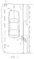
- Figure 1depicts a motor vehicle 12 travelling in a forward direction along its major axis V along a typical roadway environment generally designated 10.
- Lane boundariesare shown by lines 20, 21 and an extended roadside object 13 is illustrated to represent common roadway environmental elements such as guardrails, fences, infrastructure abutments and the like.
- Vehicle 12is equipped with a blind-zone radar system 15 operative to transmit and receive radio signals.
- the transmitted radio signalshave a radiation patter 14 substantially corresponding to the main lobe thereof.
- Radiation pattern 14has a spread angle ⁇ which also substantially corresponds to the reception pattern spread angle.
- the radiation and reception patterns showncorrespond to what is termed a vehicle blind-zone, created by obstructions and/or limited mirror viewing fields, and are intended to be used to detect the presence of hazardous objects in this zone.
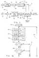
- An embodiment of blind-zone radar system 15includes (as best seen in Figure 2) a transmission antenna 41 for establishing the radio signal radiation pattern 14.
- Receiving antenna 42is configured to receive reflected radio signals within substantially the same pattern established by transmission antenna 41.
- Modulator 47is a multi-function modulator responsive to digital signals on control lines 51 and 52 to produce an analogue voltage output on line 60 for control of voltage controlled oscillator (VCO) 45.
- VCOvoltage controlled oscillator
- Modulator 47responds, for example, to a high logic signal on line 52 by outputting a constant DC voltage on line 60 so that voltage controlled oscillator 45 outputs a continuous wave (CW) radar signal on line 61.
- Modulator 47responds to a low logic signal on line 52 by outputting a linear ramped voltage on line 60 such that voltage controlled oscillator 45 outputs a frequency modulated, continuous wave (FM-CW) radar signal on line 61.
- the direction of the linear ramped voltage on line 60is dependent on the logic signal on line 51, thereby allowing both a ramped-up and a ramped-down voltage and correspondingly unique FM-CW radar signals.
- the radar signal on line 61is fed to power divider 43, at which a portion is routed to transmitting antenna 41 and another portion thereof is routed to mixer 44 via line 64.
- Mixer 44also receives radar signals from receiving antenna 42, which are reflected portions of the transmitted radar signals from antenna 41.
- the two signalsare processed in a conventional heterodyned sensor so as to produce an IF signal on line 62 at the output of mixer 44.
- the IF signalis amplified and filtered at unit 46 to remove low frequency and DC components therein.
- the output on line 63is the frequency differential between the transmitted and received signals.
- Digital processor 49operates on the basis of a control algorithm of the type shown in Figures 3a and 3b and described below, so as to control modulator 41 and to process conditioned radar signals to determine therefrom distance from and relative velocities of obstructions and to distinguish between hazardous and non-hazardous obstructions.
- Digital processor 49comprises a central processing unit with internal clock, ROM, RAM and various digital input and output ports.
- digital output line 70provides an indication via its logic state of the presence or absence of a hazardous obstruction.
- Input line 53comprises a measure of vehicle speed to the radar system to take into account varying vehicle speeds.
- routinebegins at step 100 which is executed each time the radar system operates for initialising various tables, timers, flags and the like used by the routine.
- step 100is executed each time the radar system operates for initialising various tables, timers, flags and the like used by the routine.
- a group of obstruction discrimination steps 101-112 and alternative groups of obstruction acceptance steps 120-124 or obstruction rejection steps 130-134are repeatedly executed.
- Processing steps 101-103perform radar signal transmission, reception and signal processing functions to establish well known radar data quantities.
- Step 101performs a first FM-CS radar cycle including controlling modulator 47 via control lines 51 and 52 to produce transmission of an up-sweep signal according to a linear ramp in the present embodiment, reading an amplified, filtered and digitised IF signal at input line 54 and calculating therefrom the lowest order spectral component f up such as by Fast Fourier Transform (FFT) techniques.
- the quantity f upis a rough measure of range to the obstruction off which the transmitted signal was reflected.
- Step 102performs a second FM-CW radar cycle but with a down-sweep signal according to a linear ramp and similarly calculates the lowest order spectral component f down .
- FFTFast Fourier Transform
- Step 103performs a continuous wave (CW) radar cycle and determines the CW doppler quantity f cw .
- the CW doppler quantity f cwis a pure doppler frequency difference without algebraic sign and thus a measure of relative obstruction velocity but not direction.
- Steps 101-103provide a portion of the data used to determine whether or not a hazardous object is in the path of the vehicle and the relationship of the position of such an object relative to the vehicle.
- the time intervals for the up-sweep and down-sweep FM-CW cyclesare preferably substantially equivalent so that any doppler frequency component present in the measured quantities f up and f down can be extracted in subsequent processing steps.
- Other modulating waveformssuch as rising and falling portions of a sinusoidal signal, could be used in place of the chosen linear ramps.
- linear ramp modulationis preferred since it provides relatively simple discrimination between several obstructions in comparison to non-linear modulation, such as sinusoidal waveforms would provide.
- Alternative methods and techniques for obtaining the FM-CW and CW quantitieswill be apparent to the skilled person.
- Steps 104 and 105determine whether the obstruction is within a predetermined range.
- the quantities f up and f downmay contain a doppler frequency component depending upon the relative motion between the vehicle and obstruction and thus may differ from one another. However, these quantities f up and f down provide a sufficient estimate of range for a preliminary detection of obstructions.
- Step 104compares f up to a predetermined quantity f max representing a maximum range of concern. If the quantity f up is less than f max , then the rough measure of obstruction range represented thereby is determined to be within the range of concern and step 105 is next executed.
- the quantity f downis similarly compared to f max at step 105 and if it is also less than f max then the obstruction is accepted as being within the range of concern and step 106 is next executed. If either f up or f down is greater than f max , then the current obstruction detection is immediately considered non-hazardous, no further obstruction discrimination steps need be performed and processing proceeds to obstruction rejection steps 130-134 via path 151.
- the rangemay be determined by comparing the average of quantities f up and f down with f max , which technique effectively eliminates any doppler frequency component between the two quantities averaged.
- step 106extracts the FM-CW doppler quantity f d from the FM-CW quantities f up and f down as one half of the difference between these two quantities.
- the FM-CW doppler quantity f dis a measure of the relative velocity of the obstruction.
- the FM-CW doppler quantity f dmay be positive or negative, a positive value being indicative of an approaching obstruction and a negative value being indicative of a receding obstruction.
- the first branch of a two-branched discrimination testis performed at step 107.
- the magnitude of f dis compared to a predetermined quantity W 1 representing a minimum relative obstruction velocity which will reliably indicate whether the obstruction is potentially hazardous.
- step 109sets a retained doppler quantity F d used in further processing to the FM-CW doppler quantity f d .
- F dthe strongest reflected radar signals are perpendicular to the guard rail and thus the FM-CW doppler quantity f d is a measure of the apparent velocity of the guard rail section adjacent the vehicle.
- the relative velocity between themmay cause a negative response at step 107, immediately indicating a potential hazard.
- the relative velocity and thus the magnitude of the FM-CW doppler quantity f dis correspondingly small and a positive response is made at step 107.
- step 108is next executed to compare the CW doppler quantity f cw to a predetermined quantity W 2 representing a minimum obstruction velocity which will reliably indicate whether a significant difference between the FM-CW doppler quantity f d and the CW doppler quantity f cw is detected.
- the detected obstructionis considered a potential hazard and step 109 sets the retained doppler quantity F d to the FM-CW doppler quantity f d .
- step 110sets the retained doppler quantity F d to the algebraic negative value of the CW cycle doppler quantity f cw in order to flag the detected obstruction as non-hazardous.
- the strongest reflected radar signalsare perpendicular to the guard rail.
- the IF signals produced during the FM-CW and CW cycleswill, when processed through amplifier and filter 46, produce respective frequency signals on line 63 which are the differences in frequency between the two heterodyne-processed signals for the particular cycle.
- the perpendicularly reflected signalwill, when combined with the transmitted signal in heterodyne manner, produce an IF signal on line 62 which has a high frequency content so as to pass through the filter at 46, thus producing the dominant lowest order spectral component on line 63.
- the FM-CW doppler quantity f dwill be small or non-existent, indicating minimal relative motion between the vehicle and the obstruction.
- the perpendicularly reflected signalwill produce an IF signal on line 62 which has minimal if any high frequency content due to the near zero frequency differential (zero doppler component) between the transmitted and the perpendicularly reflected signal, so as to be greatly attenuated through the filter 46, thus producing little if any high frequency spectral component on line 63.
- the dominant lowest order spectral component on line 63 during a CW cycleis therefore the result of the doppler content of the "heterodyned" reflected and transmitted CW signals.
- Non-perpendicular portions of the roadside obstructionwill have a relative velocity with the vehicle and thus the signal reflected thereby will combine with the transmitted signal to produce an IF signal having substantial high frequency content which will pass through the filter 46 to produce the dominant lowest order spectral component on line 63. Therefore, the CW doppler quantity f cw will be large, indicating relative motion between the vehicle and the obstruction.
- divergent FM-CW and CW doppler quantitiesindicate a roadside obstruction which is not hazardous.
- step 110is then executed to generate the retained doppler quantity F d , as the algebraic negative value of the CW cycle doppler quantity f cw , thereby to flag the detected obstruction as non-hazardous.
- the retained doppler quantity F dis compared to a threshold value f th representative of a closing velocity which, if exceeded, determines that the detected obstruction is hazardous.
- the threshold value f this a predetermined positive value which, in the present embodiment, is a function of vehicle speed and is preferably read from a conventional two-dimensional look-up table or alternatively calculated from a formula. Additionally, other parameters such as tyre to road friction coefficients and weather conditions may be included in determining the threshold value.
- the threshold value f thcannot be exceeded in the case where the retained doppler quantity F d was set negative at step 110, and step 112 will therefore pass processing on to a group of obstruction rejection steps 130-134. This follows since the detected obstruction has already been considered non-hazardous.
- the threshold value f thmay or may not be exceeded in the case where the retained doppler quantity F d was set at step 109, indicating a potential hazard.
- a receding obstructionwill have a negative value for the retained doppler quantity F d and cannot exceed the positive threshold value f th .
- An approaching obstructionon the other hand will have a positive value for the retained doppler quantity F d and, depending upon its magnitude, may exceed the threshold value f th .
- threshold value f thIf the threshold value f th is exceeded, then the potentially hazardous event is actually determined to be hazardous and a group of obstruction acceptance steps 120-124 is next executed. On the other hand, if the threshold value f th is not exceeded, then the potentially hazardous event is determined to be non-hazardous and a group of obstruction rejection steps 130-134 is next executed.
- the group of obstruction acceptance steps 120-124is executed to determine if the valid obstruction flag should be set.
- a set valid obstruction flag in the present embodimentindicates that a predetermined number of consecutive hazardous events has been detected.
- Step 120first determines if a valid obstruction flag is currently set. If the valid obstruction flag is set, the current hazardous event is merely cumulative, the valid obstruction flag remains set and the routine returns via line 150 to step 101 to repeat the obstruction discrimination steps. If the valid obstruction flag is not set, processing passes to step 121 which checks if this current pass through obstruction acceptance steps 120-124 is the initial pass since the last non-hazardous event was detected. If this pass represents the first time through this part of the routine, then a debounce timer is reset at step 122 and begins a count down. If this is not the first pass, the debounce timer is not reset and continues to count down. Step 123 next determines if the debounce timer has expired.
- step 124sets the valid obstruction flag which remains set so long as the group of obstruction rejection steps 130-134 does not reset it.
- the group of obstruction rejection steps 130-134is executed to determine if the valid obstruction flag should be reset.
- a reset valid obstruction flag in the present embodimentindicates that a predetermined number of consecutive non-hazardous events has been detected.
- Step 130first determines if a valid obstruction flag is currently set. If the valid obstruction flag is not set, the current non-hazardous event is merely cumulative, the valid obstruction flag remains reset and the routine returns via line 150 to step 101. If the valid obstruction flag is set, processing passes to step 131 which checks if the current pass through obstruction rejection steps 130-134 is the initial pass since the last hazardous event was detected. If it is the first pass, a hold timer is reset at step 132 and begins a count down.
- Step 133next determines if the hold time has expired. An expired hold time indicates that a sufficient number of consecutive non-hazardous events has occurred to accept the current obstruction as non-hazardous. Therefore, if the hold time has expired, step 134 resets the valid obstruction flag, which remains reset so long as the group of obstruction acceptance steps 120-124 does not set it.
Landscapes
- Engineering & Computer Science (AREA)
- Radar, Positioning & Navigation (AREA)
- Remote Sensing (AREA)
- Physics & Mathematics (AREA)
- Computer Networks & Wireless Communication (AREA)
- General Physics & Mathematics (AREA)
- Electromagnetism (AREA)
- Radar Systems Or Details Thereof (AREA)
Description
- This invention is related to a vehicleobstruction detection system and to a method ofdiscriminating between hazardous and non-hazardousobstructions, for example for discriminating hazardousobjects from various non-hazardous objects and/orclutter commonly encountered in typical automotiveenvironments.
- Many attempts have been made to providereliable discrimination of obstructions in the path ofa vehicle. Many of these attempts have used vehicularradar systems which provide data relating to the rangeof the obstruction and relative velocity between theobstruction and the vehicle. The operatingenvironment of an automotive radar system presentsmany challenges to the system designer, among the mosttroublesome being differentiation between hazardousand non-hazardous obstructions, both of which returntransmitted radar signals. Typical non-hazardousobstructions include road signs, bridges, fences,guardrails and the like. Poor discrimination of suchnon-hazards from hazards limits the effectiveness andreliability of such automotive radar systems.
- Various attempts have been made to remedythe above shortfalls. One such attempt includeslimiting the range and pattern width of signaltransmission and reception, however, this alsoundesirably limits the area of detection. This is anespecially unattractive option where, as in a vehicleblind-zone detection radar system, a relatively widearea needs to be covered.
- Other proposals for solving the aboveshortfalls include multiple transmitter and/orreceiver configurations which are complex and costly.
- Systems with variable transmitted radarpattern angle and range, responsive to steering input, have also been proposed to limit return signals fromnon-hazard obstructions of the type which aretangential to a vehicle's travel around a curve orbend. This technique may be useful for look-ahead orlook-back radar systems where radar pattern issubstantially aligned with the major axis of thevehicle but does not address the problems ofblind-zone radar systems where the transmissionpattern is intentionally at an angle from the majoraxis of the vehicle.
- Additionally, relatively complicated returnsignal processing to separate multipath signals infrequency bands have been proposed to discriminatebetween several detected obstructions.FR-A-2255610 discloses a detection system in accordance with thepreamble of Claims 1 and 2.
- The present invention seeks to provide animproved vehicle obstruction detection system and amethod of discriminating between hazardous andnon-hazardous obstructions in the vicinity of avehicle.
- According to an aspect of the presentinvention, there is provided a vehicle obstructiondetection system as specified in claim 1.
- It is possible to provide accuratediscrimination of hazardous obstructions fromnon-hazardous obstructions, without substantial orcomplex hardware and with relatively simple processingof obstruction data. Additionally, it is possible toprovide obstruction discrimination without limitingthe area covered by the system.
- A preferred embodiment uses a multimoderadar system which provides for accurate obstructiondiscrimination in an automotive application. Afrequency modulated continuous wave (FM-CW) portion oftransmitted and received signals is utilised in thedetermination of apparent velocity and range of anobstruction. A continuous wave (CW) portion oftransmitted and received signals is utilised in thedetermination of the obstruction's apparent velocity.The relationship between the range and two apparentvelocities of the obstruction determine whether theobstruction is hazardous or non-hazardous.
- An embodiment of the present invention isdescribed below, by way of example only, withreference to the accompanying drawings, in which:
- Figure 1 is a diagram illustrating anembodiment of vehicular blind-zone radar pattern inrelation to a carrying vehicle and typicalnon-hazardous obstruction;
- Figure 2 is a block diagram of an embodimentof vehicular radar system; and
- Figures 3a and 3b are flow charts of anembodiment of program instructions executed by thesystem of Figure 2 for carrying out obstructiondiscrimination.
- Figure 1 depicts a
motor vehicle 12travelling in a forward direction along its major axisV along a typical roadway environment generallydesignated 10. Lane boundaries are shown bylines roadside object 13 is illustratedto represent common roadway environmental elementssuch as guardrails, fences, infrastructure abutmentsand the like. Vehicle 12 is equipped with a blind-zoneradar system 15 operative to transmit and receive radio signals. The transmitted radio signals have aradiation patter 14 substantially corresponding to themain lobe thereof.Radiation pattern 14 has a spreadangle which also substantially corresponds to thereception pattern spread angle. The radiation andreception patterns shown correspond to what is termeda vehicle blind-zone, created by obstructions and/orlimited mirror viewing fields, and are intended to beused to detect the presence of hazardous objects inthis zone.- An embodiment of blind-
zone radar system 15includes (as best seen in Figure 2) atransmissionantenna 41 for establishing the radiosignal radiationpattern 14. Receivingantenna 42 is configured toreceive reflected radio signals within substantiallythe same pattern established bytransmission antenna 41.Modulator 47 is a multi-function modulatorresponsive to digital signals oncontrol lines line 60for control of voltage controlled oscillator (VCO) 45. Modulator 47 responds, for example, to ahigh logic signal online 52 by outputting a constantDC voltage online 60 so that voltage controlledoscillator 45 outputs a continuous wave (CW) radarsignal online 61.Modulator 47 responds to a lowlogic signal online 52 by outputting a linear rampedvoltage online 60 such that voltage controlledoscillator 45 outputs a frequency modulated,continuous wave (FM-CW) radar signal online 61. Thedirection of the linear ramped voltage online 60 isdependent on the logic signal online 51, therebyallowing both a ramped-up and a ramped-down voltageand correspondingly unique FM-CW radar signals.- The radar signal on
line 61 is fed topowerdivider 43, at which a portion is routed to transmittingantenna 41 and another portion thereof isrouted to mixer 44 vialine 64.Mixer 44 alsoreceives radar signals from receivingantenna 42,which are reflected portions of the transmitted radarsignals fromantenna 41. The two signals areprocessed in a conventional heterodyned sensor so asto produce an IF signal online 62 at the output ofmixer 44. The IF signal is amplified and filtered atunit 46 to remove low frequency and DC componentstherein. The output online 63 is the frequencydifferential between the transmitted and receivedsignals. - The resultant signal is digitised forprocessing by
digital processor 49.Digital processor 49 operates on the basis of a control algorithm of thetype shown in Figures 3a and 3b and described below,so as to controlmodulator 41 and to processconditioned radar signals to determine therefromdistance from and relative velocities of obstructionsand to distinguish between hazardous and non-hazardousobstructions.Digital processor 49 comprises acentral processing unit with internal clock, ROM, RAMand various digital input and output ports. Inaddition tocontrol lines digital outputline 70 provides an indication via its logic state ofthe presence or absence of a hazardous obstruction.Input line 53 comprises a measure of vehicle speed tothe radar system to take into account varying vehiclespeeds. - Referring to the embodiment of routine shownin Figures 3a and 3b, it begins at
step 100 which isexecuted each time the radar system operates forinitialising various tables, timers, flags and thelike used by the routine. Following initialisation, agroup of obstruction discrimination steps 101-112 and alternative groups of obstruction acceptance steps120-124 or obstruction rejection steps 130-134 arerepeatedly executed. - Processing steps 101-103 perform radarsignal transmission, reception and signal processingfunctions to establish well known radar dataquantities.
Step 101 performs a first FM-CS radarcycle including controllingmodulator 47 viacontrollines input line 54 and calculatingtherefrom the lowest order spectral component fup suchas by Fast Fourier Transform (FFT) techniques. Thequantity fup is a rough measure of range to theobstruction off which the transmitted signal wasreflected.Step 102 performs a second FM-CW radarcycle but with a down-sweep signal according to alinear ramp and similarly calculates the lowest orderspectral component fdown.Step 103 performs acontinuous wave (CW) radar cycle and determines the CWdoppler quantity fcw. The CW doppler quantity fcw is apure doppler frequency difference without algebraicsign and thus a measure of relative obstructionvelocity but not direction. - Steps 101-103 provide a portion of the dataused to determine whether or not a hazardous object isin the path of the vehicle and the relationship of theposition of such an object relative to the vehicle.It is here noted that the time intervals for theup-sweep and down-sweep FM-CW cycles are preferablysubstantially equivalent so that any doppler frequencycomponent present in the measured quantities fup andfdown can be extracted in subsequent processing steps.Other modulating waveforms, such as rising and falling portions of a sinusoidal signal, could be used inplace of the chosen linear ramps. However, linearramp modulation is preferred since it providesrelatively simple discrimination between severalobstructions in comparison to non-linear modulation,such as sinusoidal waveforms would provide.Alternative methods and techniques for obtaining theFM-CW and CW quantities will be apparent to theskilled person.
Steps Step 104compares fup to a predetermined quantity fmaxrepresenting a maximum range of concern. If thequantity fup is less than fmax, then the rough measureof obstruction range represented thereby is determinedto be within the range of concern and step 105 is nextexecuted. The quantity fdown is similarly compared tofmax atstep 105 and if it is also less than fmax thenthe obstruction is accepted as being within the rangeof concern and step 106 is next executed. If eitherfup or fdown is greater than fmax, then the currentobstruction detection is immediately considerednon-hazardous, no further obstruction discriminationsteps need be performed and processing proceeds toobstruction rejection steps 130-134 viapath 151.Alternatively, the range may be determined bycomparing the average of quantities fup and fdown withfmax, which technique effectively eliminates any doppler frequency component between the two quantitiesaveraged.- Proceeding with the assumption that thepreliminary check has determined that the obstructionis within the range of concern,
step 106 extracts theFM-CW doppler quantity fd from the FM-CW quantities fupand fdown as one half of the difference between thesetwo quantities. The FM-CW doppler quantity fd is ameasure of the relative velocity of the obstruction.The FM-CW doppler quantity fd may be positive ornegative, a positive value being indicative of anapproaching obstruction and a negative value beingindicative of a receding obstruction. The firstbranch of a two-branched discrimination test isperformed atstep 107. The magnitude of fd iscompared to a predetermined quantity W1 representing aminimum relative obstruction velocity which willreliably indicate whether the obstruction ispotentially hazardous. Where the magnitude of fd isequal to or greater than W1, the detected obstructionis considered potentially hazardous and step 109 setsa retained doppler quantity Fd used in furtherprocessing to the FM-CW doppler quantity fd. In thecase of a roadside obstruction, for example a guardrail, the strongest reflected radar signals areperpendicular to the guard rail and thus the FM-CWdoppler quantity fd is a measure of the apparentvelocity of the guard rail section adjacent thevehicle. Where the vehicle is closing in on the guardrail, the relative velocity between them may cause anegative response atstep 107, immediately indicatinga potential hazard. Alternatively, where the vehicletravel is substantially parallel to the guardrail, therelative velocity and thus the magnitude of the FM-CW doppler quantity fd is correspondingly small and apositive response is made atstep 107. - When the result at
step 107 is positive,step 108 is next executed to compare the CW dopplerquantity fcw to a predetermined quantity W2representing a minimum obstruction velocity which willreliably indicate whether a significant differencebetween the FM-CW doppler quantity fd and the CWdoppler quantity fcw is detected. In the case wherethe magnitude of the FM-CW doppler quantity fd issmall (indicating little or no apparent relativemotion between the vehicle and obstruction) and the CWdoppler quantity fcw is also small (likewiseindicating little or no apparent relative motionbetween the vehicle and obstruction), the detectedobstruction is considered a potential hazard and step109 sets the retained doppler quantity Fd to the FM-CWdoppler quantity fd. In the case where the magnitudeof the FM-CW doppler quantity fd is small (indicatingno apparent relative motion between the vehicle andobstruction) and the CW doppler quantity fcw is large(indicating apparent relative motion between thevehicle and obstruction), the detected obstruction isconsidered non-hazardous and step 110 sets theretained doppler quantity Fd to the algebraic negativevalue of the CW cycle doppler quantity fcw in order toflag the detected obstruction as non-hazardous. Thedivergent FM-CW and CW doppler quantities areexplained and resolved as follows with reference toFigure 2. - As mentioned above in relation to asituation in which the
vehicle 12 is adjacent aroadside obstruction such as a guard rail, thestrongest reflected radar signals are perpendicular tothe guard rail. The IF signals produced during the FM-CW and CW cycles will, when processed throughamplifier andfilter 46, produce respective frequencysignals online 63 which are the differences infrequency between the two heterodyne-processed signalsfor the particular cycle. In the case of an FM-CWcycle with a roadside obstruction, the perpendicularlyreflected signal will, when combined with thetransmitted signal in heterodyne manner, produce an IFsignal online 62 which has a high frequency contentso as to pass through the filter at 46, thus producingthe dominant lowest order spectral component online 63. Therefore, the FM-CW doppler quantity fd will besmall or non-existent, indicating minimal relativemotion between the vehicle and the obstruction.However, in the case of a CW cycle with the sameroadside obstruction, the perpendicularly reflectedsignal will produce an IF signal online 62 which hasminimal if any high frequency content due to the nearzero frequency differential (zero doppler component)between the transmitted and the perpendicularlyreflected signal, so as to be greatly attenuatedthrough thefilter 46, thus producing little if anyhigh frequency spectral component online 63. - The dominant lowest order spectral componenton
line 63 during a CW cycle is therefore the resultof the doppler content of the "heterodyned" reflectedand transmitted CW signals. Non-perpendicularportions of the roadside obstruction will have arelative velocity with the vehicle and thus the signalreflected thereby will combine with the transmittedsignal to produce an IF signal having substantial highfrequency content which will pass through thefilter 46 to produce the dominant lowest order spectralcomponent online 63. Therefore, the CW dopplerquantity fcw will be large, indicating relative motion between the vehicle and the obstruction. Where thedecisions atsteps step 110 is then executed to generatethe retained doppler quantity Fd, as the algebraicnegative value of the CW cycle doppler quantity fcw,thereby to flag the detected obstruction asnon-hazardous. - After the retained doppler quantity Fd isset at
step step 112. The retained dopplerquantity Fd is compared to a threshold value fthrepresentative of a closing velocity which, ifexceeded, determines that the detected obstruction ishazardous. The threshold value fth is a predeterminedpositive value which, in the present embodiment, is afunction of vehicle speed and is preferably read froma conventional two-dimensional look-up table oralternatively calculated from a formula.Additionally, other parameters such as tyre to roadfriction coefficients and weather conditions may beincluded in determining the threshold value. Thethreshold value fth cannot be exceeded in the casewhere the retained doppler quantity Fd was setnegative atstep 110, and step 112 will therefore passprocessing on to a group of obstruction rejectionsteps 130-134. This follows since the detectedobstruction has already been considered non-hazardous.The threshold value fth may or may not be exceeded inthe case where the retained doppler quantity Fd wasset atstep 109, indicating a potential hazard. Areceding obstruction will have a negative value forthe retained doppler quantity Fd and cannot exceed thepositive threshold value fth. An approaching obstruction on the other hand will have a positivevalue for the retained doppler quantity Fd and,depending upon its magnitude, may exceed the thresholdvalue fth. If the threshold value fth is exceeded,then the potentially hazardous event is actuallydetermined to be hazardous and a group of obstructionacceptance steps 120-124 is next executed. On theother hand, if the threshold value fth is notexceeded, then the potentially hazardous event isdetermined to be non-hazardous and a group ofobstruction rejection steps 130-134 is next executed. - When the threshold value fth is exceeded,the group of obstruction acceptance steps 120-124 isexecuted to determine if the valid obstruction flagshould be set. A set valid obstruction flag in thepresent embodiment indicates that a predeterminednumber of consecutive hazardous events has beendetected.
- Step 120 first determines if a validobstruction flag is currently set. If the validobstruction flag is set, the current hazardous eventis merely cumulative, the valid obstruction flagremains set and the routine returns via
line 150 tostep 101 to repeat the obstruction discriminationsteps. If the valid obstruction flag is not set,processing passes to step 121 which checks if thiscurrent pass through obstruction acceptance steps120-124 is the initial pass since the lastnon-hazardous event was detected. If this passrepresents the first time through this part of theroutine, then a debounce timer is reset atstep 122and begins a count down. If this is not the firstpass, the debounce timer is not reset and continues tocount down. Step 123 next determines if the debouncetimer has expired. An expired debounce timer indicates that a sufficient number of consecutivehazardous events has occurred to accept the currentobstruction as hazardous. Therefore, if the debouncetime has expired,step 124 sets the valid obstructionflag which remains set so long as the group ofobstruction rejection steps 130-134 does not reset it. - When the threshold value fth is not exceededor the obstruction is out of range, the group ofobstruction rejection steps 130-134 is executed todetermine if the valid obstruction flag should bereset. A reset valid obstruction flag in the presentembodiment indicates that a predetermined number ofconsecutive non-hazardous events has been detected.Step 130 first determines if a valid obstruction flagis currently set. If the valid obstruction flag isnot set, the current non-hazardous event is merelycumulative, the valid obstruction flag remains resetand the routine returns via
line 150 to step 101. Ifthe valid obstruction flag is set, processing passesto step 131 which checks if the current pass throughobstruction rejection steps 130-134 is the initialpass since the last hazardous event was detected. Ifit is the first pass, a hold timer is reset atstep 132 and begins a count down. If it is not the firstpass, the hold timer is not reset and continues tocount down. Step 133 next determines if the hold timehas expired. An expired hold time indicates that asufficient number of consecutive non-hazardous eventshas occurred to accept the current obstruction asnon-hazardous. Therefore, if the hold time hasexpired,step 134 resets the valid obstruction flag,which remains reset so long as the group ofobstruction acceptance steps 120-124 does not set it. - The precise process of accepting andrejecting groups of sequential hazardous and non-hazardous events disclosed above is unnecessary tothe actual discrimination between hazardous andnon-hazardous events which preceded it, and is onlydescribed to illustrate the preferred embodiment.
Claims (4)
- A vehicle obstruction detection system for discriminatingbetween hazardous and non-hazardous obstructions, including transmittingmeans (41, 43, 45, 47) for transmitting a frequency modulated continuouswave (FMCW) signal and a continuous wave (CW) signal, receiving means(42) for receiving reflections of the FMCW and CW signals reflected off anobstruction, and processing means (49) for determining a first measure ofrelative velocity of the obstruction based on the CW signal and its reflection,characterized by:means (49) for determining a second measure of the relativevelocity of the obstruction based on the FMCW signal and its reflection; andcomparator means (49) for comparing said first and second measures and fordetermining that the obstruction is non-hazardous when the comparisonindicates a significant difference between said first and second measures.
- A vehicle obstruction detection system for discriminatingbetween hazardous and non-hazardous obstructions, including transmittingmeans (41, 43, 45, 47) for transmitting a frequency modulated continuouswave (FMCW) signal and a continuous wave (CW) signal, receiving means(42) for receiving reflections of the FMCW and CW signals reflected off anobstruction, and processing means (49) for determining a measure of relativevelocity of the obstruction based on the CW signal and its reflection,characterized by:means (49) for determining a doppler quantity from the FMCWsignal and its reflection; and identifying means (49) operative to determinethat the obstruction is non-hazardous when the determined doppler quantitycontradicts the determined measure of relative velocity.
- A vehicle obstruction detection system according to claim 1or 2, wherein the FMCW signal is linearly modulated.
- A vehicle obstruction detection system according to claim 1,2 or 3, wherein the FMCW and CW signals are radar signals.
Applications Claiming Priority (2)
| Application Number | Priority Date | Filing Date | Title |
|---|---|---|---|
| US08/069,470US5325097A (en) | 1993-06-01 | 1993-06-01 | Multimode radar for road vehicle blind-zone target discrimination |
| US69470 | 1993-06-01 |
Publications (3)
| Publication Number | Publication Date |
|---|---|
| EP0627634A2 EP0627634A2 (en) | 1994-12-07 |
| EP0627634A3 EP0627634A3 (en) | 1996-04-17 |
| EP0627634B1true EP0627634B1 (en) | 2000-09-06 |
Family
ID=22089180
Family Applications (1)
| Application Number | Title | Priority Date | Filing Date |
|---|---|---|---|
| EP94201291AExpired - LifetimeEP0627634B1 (en) | 1993-06-01 | 1994-05-09 | Vehicle obstruction detection system |
Country Status (4)
| Country | Link |
|---|---|
| US (1) | US5325097A (en) |
| EP (1) | EP0627634B1 (en) |
| JP (1) | JPH06347545A (en) |
| DE (1) | DE69425779T2 (en) |
Families Citing this family (63)
| Publication number | Priority date | Publication date | Assignee | Title |
|---|---|---|---|---|
| US5517196A (en)* | 1992-08-14 | 1996-05-14 | Pakett; Allan G. | Smart blind spot sensor with object ranging |
| DE4242700C2 (en)* | 1992-12-17 | 2003-01-30 | Bosch Gmbh Robert | Procedure for measuring the distance and speed of objects |
| US6664920B1 (en)* | 1993-11-18 | 2003-12-16 | Raytheon Company | Near-range microwave detection for frequency-modulation continuous-wave and stepped frequency radar systems |
| US5530447A (en)* | 1995-01-13 | 1996-06-25 | Delco Electronics Corp. | Blind-zone target discrimination method and system for road vehicle radar |
| EP0699924B1 (en)* | 1994-08-24 | 1999-10-06 | Delco Electronics Corporation | Vehicle obstruction discrimination system |
| JP3550829B2 (en)* | 1995-01-24 | 2004-08-04 | 株式会社デンソー | FM-CW radar device |
| DE19538309C2 (en)* | 1995-10-14 | 1998-10-15 | Volkswagen Ag | Radar method for measuring distances and relative speeds between a vehicle and one or more obstacles |
| US5670962A (en)* | 1995-11-13 | 1997-09-23 | Delco Electronics Corp. | Transmit power control for automotive radar system |
| DE19600059C2 (en)* | 1996-01-03 | 1999-04-15 | Daimler Benz Ag | Method for signal processing in a motor vehicle radar arrangement and radar arrangement therefor |
| US6011507A (en)* | 1996-11-12 | 2000-01-04 | Raytheon Company | Radar system and method of operating same |
| US5929802A (en)* | 1997-11-21 | 1999-07-27 | Raytheon Company | Automotive forward looking sensor application |
| SE511061C2 (en)* | 1997-11-21 | 1999-07-26 | Celsiustech Electronics Ab | Procedure for classifying raised objects |
| DE19803660C2 (en)* | 1998-01-30 | 2001-07-05 | Siemens Ag | Motor vehicle radar |
| US6127965A (en)* | 1998-07-23 | 2000-10-03 | Eaton-Vorad Technologies, L.L.C. | Method and apparatus for rejecting rain clutter in a radar system |
| US6438491B1 (en) | 1999-08-06 | 2002-08-20 | Telanon, Inc. | Methods and apparatus for stationary object detection |
| US6777684B1 (en) | 1999-08-23 | 2004-08-17 | Rose Research L.L.C. | Systems and methods for millimeter and sub-millimeter wave imaging |
| JP2004506906A (en)* | 2000-08-16 | 2004-03-04 | レイセオン・カンパニー | Automotive radar system and method |
| US6707419B2 (en)* | 2000-08-16 | 2004-03-16 | Raytheon Company | Radar transmitter circuitry and techniques |
| JP4928052B2 (en)* | 2000-08-16 | 2012-05-09 | ヴァレオ・レイダー・システムズ・インコーポレーテッド | Switched beam antenna architecture |
| JP2004505844A (en)* | 2000-08-16 | 2004-02-26 | レイセオン・カンパニー | Safe distance algorithm for adaptive cruise control |
| US20020075138A1 (en)* | 2000-08-16 | 2002-06-20 | Van Rees H. Barteld | Portable object detection system |
| JP5063851B2 (en)* | 2000-08-16 | 2012-10-31 | ヴァレオ・レイダー・システムズ・インコーポレーテッド | Proximity object detection system |
| KR100776868B1 (en)* | 2000-08-16 | 2007-11-16 | 레이던 컴퍼니 | Video Amplifiers for Radar Receivers |
| US6675094B2 (en)* | 2000-09-08 | 2004-01-06 | Raytheon Company | Path prediction system and method |
| RU2218582C2 (en)* | 2001-04-02 | 2003-12-10 | Кошуринов Евгений Иванович | Facility measuring range |
| WO2002041026A2 (en)* | 2000-11-16 | 2002-05-23 | Krislamov, Gennady Alekseevich | Distance measuring method and device |
| US6708100B2 (en)* | 2001-03-14 | 2004-03-16 | Raytheon Company | Safe distance algorithm for adaptive cruise control |
| JP3788322B2 (en)* | 2001-05-30 | 2006-06-21 | 株式会社村田製作所 | Radar |
| US6995730B2 (en)* | 2001-08-16 | 2006-02-07 | Raytheon Company | Antenna configurations for reduced radar complexity |
| US6970142B1 (en) | 2001-08-16 | 2005-11-29 | Raytheon Company | Antenna configurations for reduced radar complexity |
| US7183995B2 (en) | 2001-08-16 | 2007-02-27 | Raytheon Company | Antenna configurations for reduced radar complexity |
| RU2239845C2 (en)* | 2002-07-22 | 2004-11-10 | Кошуринов Евгений Иванович | Method and system for radar measurement of speeds and co-ordinates of objects (modifications) |
| JP3964362B2 (en)* | 2002-07-26 | 2007-08-22 | 株式会社日立製作所 | Radio wave radar device and inter-vehicle distance control device |
| US6611227B1 (en) | 2002-08-08 | 2003-08-26 | Raytheon Company | Automotive side object detection sensor blockage detection system and related techniques |
| RU2255352C2 (en)* | 2003-07-07 | 2005-06-27 | Кошуринов Евгений Иванович | Method and system for radar measurement of object speeds and coordinates (modifications) |
| PL1735637T4 (en)* | 2004-04-05 | 2019-08-30 | Weibel Scientific A/S | System and method for radar detection of an object |
| WO2006094510A1 (en)* | 2005-03-11 | 2006-09-14 | Weibel Scientific A/S | Fm-cw radar |
| JP4188336B2 (en)* | 2005-04-12 | 2008-11-26 | 本田技研工業株式会社 | Object detection device |
| JP4871104B2 (en)* | 2006-11-24 | 2012-02-08 | 日立オートモティブシステムズ株式会社 | Radar apparatus and signal processing method |
| JP5653901B2 (en)* | 2008-03-31 | 2015-01-14 | ヴァレオ・レイダー・システムズ・インコーポレーテッド | Automotive radar sensor blockage detection device |
| US20110025548A1 (en)* | 2009-07-31 | 2011-02-03 | Gm Global Technology Operations, Inc. | System and method for vehicle sensor fusion |
| FR2993845B1 (en)* | 2012-07-25 | 2014-08-15 | Peugeot Citroen Automobiles Sa | CHANNEL CHANGE ASSISTANCE SYSTEM FOR A VEHICLE |
| DE102012220773A1 (en) | 2012-11-14 | 2014-05-15 | Robert Bosch Gmbh | Device and method for elevation angle determination in a radar system |
| US9261590B1 (en)* | 2013-02-27 | 2016-02-16 | Google Inc. | Adaptive algorithms for interrogating the viewable scene of an automotive radar |
| US10222462B2 (en) | 2013-02-27 | 2019-03-05 | Waymo Llc | Adaptive algorithms for interrogating the viewable scene of an automotive radar |
| RU2524482C1 (en)* | 2013-07-02 | 2014-07-27 | Валерий Владимирович Хуторцев | Method for single-position radar location of mobile objects on road network |
| RU2533198C1 (en)* | 2013-08-14 | 2014-11-20 | Открытое акционерное общество "Научно-исследовательский институт приборостроения имени В.В. Тихомирова" | Method of controlling radar station resolution |
| KR101896726B1 (en)* | 2013-12-02 | 2018-09-07 | 주식회사 만도 | Method and apparatus for detecting surrounding environment based on sensing signal of frequency modulated continuous wave radar and continuous wave radar |
| RU2566662C1 (en)* | 2014-07-04 | 2015-10-27 | Акционерное общество "Концерн радиостроения "Вега" (АО "Концерн "Вега") | Method to measure speed and azimuthal coordinate of above-water targets of radars with synthesized antenna aperture |
| US10254391B2 (en)* | 2014-12-15 | 2019-04-09 | Jj Corp | Radar detector for recognizing user's motion |
| JP2017090143A (en)* | 2015-11-06 | 2017-05-25 | 富士通テン株式会社 | Radar device, signal processing device for radar device, and signal processing method |
| DE102015226443A1 (en)* | 2015-12-22 | 2017-06-22 | Robert Bosch Gmbh | Radar sensor, corresponding operating method and vehicle |
| DE102016202936A1 (en)* | 2016-02-25 | 2017-08-31 | Robert Bosch Gmbh | Device for determining operating data for a radar sensor |
| DE102017200706A1 (en)* | 2017-01-18 | 2018-07-19 | Robert Bosch Gmbh | Multiple subsampled chirp sequence radar |
| US20190383930A1 (en)* | 2017-04-18 | 2019-12-19 | Limited Liability Company "Innovative Center Jewel" | Method and device for radar determination of the coordinates and speed of objects |
| DE102017209628A1 (en)* | 2017-06-08 | 2018-12-13 | Robert Bosch Gmbh | FMCW radar sensor for motor vehicles |
| RU2660159C1 (en)* | 2017-07-31 | 2018-07-05 | Акционерное общество "Научно-исследовательский институт Приборостроения имени В.В. Тихомирова" | Method of side-looking airborne radar determination of aircraft demolition angle |
| JP7033375B2 (en)* | 2017-09-29 | 2022-03-10 | 株式会社デンソーテン | Radar device and adjustment method of radar device |
| RU2699240C1 (en)* | 2018-04-18 | 2019-09-04 | Федеральное государственное казенное военное образовательное учреждение высшего образования "Военный учебно-научный центр Военно-воздушных сил "Военно-воздушная академия имени профессора Н.Е. Жуковского и Ю.А. Гагарина" (г. Воронеж) Министерства обороны Российской Федерации | Method of determining coordinates of target in radar station with continuous emission |
| US11474230B2 (en)* | 2018-10-26 | 2022-10-18 | Metawave Corporation | Method and apparatus for non-line-of-sight detection and coded radar signals |
| CN112526498B (en)* | 2019-08-29 | 2023-12-12 | 比亚迪股份有限公司 | Target detection method and device for vehicle and vehicle-mounted radar |
| KR102312939B1 (en)* | 2020-04-17 | 2021-10-14 | 국방과학연구소 | Multi-Target Detection Apparatus and Method |
| CN119064912A (en)* | 2023-06-01 | 2024-12-03 | 霍尼韦尔国际公司 | Method and device for speed measurement using radar sensor |
Family Cites Families (7)
| Publication number | Priority date | Publication date | Assignee | Title |
|---|---|---|---|---|
| US3611370A (en)* | 1968-11-05 | 1971-10-05 | North American Rockwell | Dual-mode radar system |
| GB1495387A (en)* | 1973-12-22 | 1977-12-14 | Lucas Ltd Joseph | Road vehicle radar system |
| US4011563A (en)* | 1976-02-06 | 1977-03-08 | Rca Corporation | Variable range automotive radar system |
| US4348675A (en)* | 1979-05-23 | 1982-09-07 | Honda Giken Kogyo Kabushiki Kaisha | FM-CW Radar system for use in an automotive vehicle |
| US4916450A (en)* | 1988-05-12 | 1990-04-10 | Radar Control Systems Corporation | Radar system for headway control of a vehicle |
| US5087918A (en)* | 1990-04-02 | 1992-02-11 | Delco Electronics Corporation | FMCW/2FD implementation for vehicle near obstacle detection system |
| GB9107476D0 (en)* | 1991-04-09 | 1991-05-22 | Peek Traffic Ltd | Improvements in vehicle detection systems |
- 1993
- 1993-06-01USUS08/069,470patent/US5325097A/ennot_activeExpired - Lifetime
- 1994
- 1994-05-09EPEP94201291Apatent/EP0627634B1/ennot_activeExpired - Lifetime
- 1994-05-09DEDE69425779Tpatent/DE69425779T2/ennot_activeExpired - Fee Related
- 1994-05-25JPJP6111213Apatent/JPH06347545A/enactivePending
Also Published As
| Publication number | Publication date |
|---|---|
| US5325097A (en) | 1994-06-28 |
| DE69425779T2 (en) | 2001-01-04 |
| EP0627634A3 (en) | 1996-04-17 |
| DE69425779D1 (en) | 2000-10-12 |
| JPH06347545A (en) | 1994-12-22 |
| EP0627634A2 (en) | 1994-12-07 |
Similar Documents
| Publication | Publication Date | Title |
|---|---|---|
| EP0627634B1 (en) | Vehicle obstruction detection system | |
| EP1371997B1 (en) | Method for detecting stationary object on road by radar | |
| US6661370B2 (en) | Radar data processing apparatus and data processing method | |
| EP1357394B1 (en) | Still object detecting method of scanning radar | |
| US5430450A (en) | Method and apparatus for automatically dimming motor vehicle headlights using radar signal | |
| EP1315980B1 (en) | Path prediction system and method | |
| US6317073B1 (en) | FM-CW radar system for measuring distance to and relative speed of a target | |
| EP1369705B1 (en) | Signal processing method for scanning radar | |
| US8077075B2 (en) | Object verification method for use in radar systems for motor vehicles | |
| EP1310804B1 (en) | Scan type radar device | |
| US10473760B2 (en) | Radar device and vertical axis-misalignment detecting method | |
| US8581774B2 (en) | Method for detecting precipitation using a radar locating device for motor vehicles | |
| WO2011070426A2 (en) | Obstacle detection device | |
| GB2327821A (en) | FMCW radar collision warning system | |
| CN101573633A (en) | Method for operating a radar and a radar | |
| EP2583116B1 (en) | Radar system and detection method | |
| WO2011158081A1 (en) | Radar system and detection method | |
| JP4079739B2 (en) | Automotive radar equipment | |
| US5940024A (en) | Onboard radar system for a vehicle | |
| EP0583418B1 (en) | Multi-frequency automotive radar system | |
| JP3737048B2 (en) | Radar equipment | |
| Yamada et al. | Development of a 60 GHz radar for rear-end collision avoidance | |
| JPH06214017A (en) | Frequency modulation radar device | |
| JPH07234277A (en) | Obstacle detection device | |
| JP3275490B2 (en) | Obstacle detection device |
Legal Events
| Date | Code | Title | Description |
|---|---|---|---|
| PUAI | Public reference made under article 153(3) epc to a published international application that has entered the european phase | Free format text:ORIGINAL CODE: 0009012 | |
| AK | Designated contracting states | Kind code of ref document:A2 Designated state(s):DE FR GB NL | |
| PUAL | Search report despatched | Free format text:ORIGINAL CODE: 0009013 | |
| AK | Designated contracting states | Kind code of ref document:A3 Designated state(s):DE FR GB NL | |
| 17P | Request for examination filed | Effective date:19961017 | |
| 17Q | First examination report despatched | Effective date:19990315 | |
| GRAG | Despatch of communication of intention to grant | Free format text:ORIGINAL CODE: EPIDOS AGRA | |
| GRAG | Despatch of communication of intention to grant | Free format text:ORIGINAL CODE: EPIDOS AGRA | |
| GRAH | Despatch of communication of intention to grant a patent | Free format text:ORIGINAL CODE: EPIDOS IGRA | |
| GRAH | Despatch of communication of intention to grant a patent | Free format text:ORIGINAL CODE: EPIDOS IGRA | |
| GRAA | (expected) grant | Free format text:ORIGINAL CODE: 0009210 | |
| AK | Designated contracting states | Kind code of ref document:B1 Designated state(s):DE FR GB NL | |
| REF | Corresponds to: | Ref document number:69425779 Country of ref document:DE Date of ref document:20001012 | |
| ET | Fr: translation filed | ||
| PLBE | No opposition filed within time limit | Free format text:ORIGINAL CODE: 0009261 | |
| STAA | Information on the status of an ep patent application or granted ep patent | Free format text:STATUS: NO OPPOSITION FILED WITHIN TIME LIMIT | |
| 26N | No opposition filed | ||
| REG | Reference to a national code | Ref country code:GB Ref legal event code:IF02 | |
| REG | Reference to a national code | Ref country code:GB Ref legal event code:732E | |
| PGFP | Annual fee paid to national office [announced via postgrant information from national office to epo] | Ref country code:GB Payment date:20050506 Year of fee payment:12 | |
| PGFP | Annual fee paid to national office [announced via postgrant information from national office to epo] | Ref country code:NL Payment date:20050513 Year of fee payment:12 | |
| PGFP | Annual fee paid to national office [announced via postgrant information from national office to epo] | Ref country code:FR Payment date:20050516 Year of fee payment:12 | |
| PG25 | Lapsed in a contracting state [announced via postgrant information from national office to epo] | Ref country code:GB Free format text:LAPSE BECAUSE OF NON-PAYMENT OF DUE FEES Effective date:20060509 | |
| PG25 | Lapsed in a contracting state [announced via postgrant information from national office to epo] | Ref country code:NL Free format text:LAPSE BECAUSE OF NON-PAYMENT OF DUE FEES Effective date:20061201 | |
| GBPC | Gb: european patent ceased through non-payment of renewal fee | Effective date:20060509 | |
| NLV4 | Nl: lapsed or anulled due to non-payment of the annual fee | Effective date:20061201 | |
| REG | Reference to a national code | Ref country code:FR Ref legal event code:ST Effective date:20070131 | |
| PG25 | Lapsed in a contracting state [announced via postgrant information from national office to epo] | Ref country code:FR Free format text:LAPSE BECAUSE OF NON-PAYMENT OF DUE FEES Effective date:20060531 | |
| PGFP | Annual fee paid to national office [announced via postgrant information from national office to epo] | Ref country code:DE Payment date:20090511 Year of fee payment:16 | |
| PG25 | Lapsed in a contracting state [announced via postgrant information from national office to epo] | Ref country code:DE Free format text:LAPSE BECAUSE OF NON-PAYMENT OF DUE FEES Effective date:20101201 |