EP0624523A1 - Two-parts container - Google Patents
Two-parts containerDownload PDFInfo
- Publication number
- EP0624523A1 EP0624523A1EP93107662AEP93107662AEP0624523A1EP 0624523 A1EP0624523 A1EP 0624523A1EP 93107662 AEP93107662 AEP 93107662AEP 93107662 AEP93107662 AEP 93107662AEP 0624523 A1EP0624523 A1EP 0624523A1
- Authority
- EP
- European Patent Office
- Prior art keywords
- vessel
- wall
- edge
- lid
- pot
- Prior art date
- Legal status (The legal status is an assumption and is not a legal conclusion. Google has not performed a legal analysis and makes no representation as to the accuracy of the status listed.)
- Withdrawn
Links
Images


Classifications
- B—PERFORMING OPERATIONS; TRANSPORTING
- B65—CONVEYING; PACKING; STORING; HANDLING THIN OR FILAMENTARY MATERIAL
- B65D—CONTAINERS FOR STORAGE OR TRANSPORT OF ARTICLES OR MATERIALS, e.g. BAGS, BARRELS, BOTTLES, BOXES, CANS, CARTONS, CRATES, DRUMS, JARS, TANKS, HOPPERS, FORWARDING CONTAINERS; ACCESSORIES, CLOSURES, OR FITTINGS THEREFOR; PACKAGING ELEMENTS; PACKAGES
- B65D21/00—Nestable, stackable or joinable containers; Containers of variable capacity
- B65D21/02—Containers specially shaped, or provided with fittings or attachments, to facilitate nesting, stacking, or joining together
- B65D21/0234—Nestable or stackable container parts forming a receptacle when one part is inverted upon the other
- B—PERFORMING OPERATIONS; TRANSPORTING
- B65—CONVEYING; PACKING; STORING; HANDLING THIN OR FILAMENTARY MATERIAL
- B65D—CONTAINERS FOR STORAGE OR TRANSPORT OF ARTICLES OR MATERIALS, e.g. BAGS, BARRELS, BOTTLES, BOXES, CANS, CARTONS, CRATES, DRUMS, JARS, TANKS, HOPPERS, FORWARDING CONTAINERS; ACCESSORIES, CLOSURES, OR FITTINGS THEREFOR; PACKAGING ELEMENTS; PACKAGES
- B65D11/00—Containers having bodies formed by interconnecting or uniting two or more rigid, or substantially rigid, components made wholly or mainly of plastics material
- B65D11/10—Containers having bodies formed by interconnecting or uniting two or more rigid, or substantially rigid, components made wholly or mainly of plastics material of polygonal cross-section and all parts being permanently connected to each other
Definitions
- Containers or vessels for storing objects of all kindsare known.
- genre formationreference is made, for example, to GM 91 03 868, DE 33 12 176 A1 or US Pat. No. 3,565,146.
- the present innovationrelates to a container or vessel as shown, for example, in FIGS. 1-6 on plant sheet 1.
- Appendix sheets 2-4show details of these vessels.
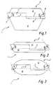
- thisis a vessel which basically consists of a lower vessel 1 (lower part) and an upper vessel 2 or lid or attachment 2.
- the adaptation of the lower part 1 to the upper part 2is the same in all the different embodiments of the innovation, with an indirect positive connection, ie a certain toothing by means of incisions 3 and 4 respectively adapted to one another.
- the proposed "toothing"does not represent a direct positive fit.
- Half of the outer wall of the upper vessellies linearly against the inner wall of the lower vessel.
- half of the inner wall of the upper vessellies linearly against the outer wall of the lower vessel.
- the two (or more) teeth of the vesselsform handles (for example when separating the closed vessels).
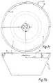
- the lower part 1, 5 shown in FIG. 1is shown, for example, in longitudinal section in FIG. 7a, in side view in FIG. 7b and in plan view in FIG. 7c.
- the incision 3extends approximately over an angular range ⁇ 1 ⁇ 90 ° with a height h1.
- the incisions 3, 4extend from the upper edge 6 of the vessel 5.
- the side wall of the vesselis generally conical.
- the two remaining webs 7, 8 of the lower part 5extend to the upper edge 6. As can be seen from FIGS.
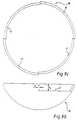
- the lid-like structure 2, 9 shown in FIG. 1is placed on such a lower part 5, as is shown, for example, in FIGS. 8a-8c.
- the lid-like structure 9also consists of a conical vessel with corresponding incisions 3 ', 4' and webs 7 ', 8', which in principle have the same structure as described for FIGS. 7a-7c. Reference is made to the corresponding description.
- the lid 2, 9 shown in FIG. 1can optionally also be designed as a lower part with an upper part of the same design.
- the lower part 10is accordingly of the same design as the upper part 11, the outer cross section not being conical like FIG. 1, but rather spherical.
- the connection between The upper part and lower parthave the same design as described for FIG. 1.
- FIG. 3consists of a lower part 12 and upper part 13, each of the same design, which have an even more spherical outer structure.
- the lower part 14 shown in Fig. 5is shown in Fig. 4 alone. It is conical in its upper region 15 and cylindrical in its lower region 16.
- the associated cover 17 in FIG. 5is designed in the same way as the cover 9 in FIG. 1.
- FIG. 6shows a lower part 5 as it corresponds to the lower part 5 in FIG. 1.
- this lower partis conical or frustoconical with angles that open upwards.
- the associated cover 18is designed as a spherical segment and is shown again in more detail in the system sheet 4 under FIGS. 9a-9c.
- the coveragain has recesses 3 ', 4' and webs 7 ', 8' as described for the exemplary embodiment according to FIGS. 8a-8c.
- the basic principle of the vesselwhich is diverse in its design, is the adaptation of the lower part 1 to the upper part 2 with the corresponding wall incisions 3, 4 'or 3', 4 ', which mesh with one another.
- the lower part of the vessel and the lidare at least in their edge area or completely identical parts.
- the part that serves as the lidis turned inside out (rotation around a horizontal axis) and positively placed on the lower part. This creates a closed outside and an enlarged enclosed volume.
Landscapes
- Engineering & Computer Science (AREA)
- Mechanical Engineering (AREA)
- Food-Manufacturing Devices (AREA)
Abstract
Translated fromGerman
Description
Translated fromGermanBehältnisse bzw. Gefäße zum Aufbewahren von Gegenständen aller Art sind bekannt. Zur Gattungsbildung wird beispielsweise auf die GM 91 03 868, DE 33 12 176 A1 oder die US 3,565,146 verwiesen.Containers or vessels for storing objects of all kinds are known. For genre formation, reference is made, for example, to GM 91 03 868, DE 33 12 176 A1 or US Pat. No. 3,565,146.
Die vorliegende Neuerung bezieht sich auf ein Behältnis oder Gefäß wie es beispielsweise in den Fig. 1 - 6 auf Anlagenblatt 1 gezeigt ist. Die Anlagenblätter 2 - 4 zeigen Einzelheiten dieser Gefäße.The present innovation relates to a container or vessel as shown, for example, in FIGS. 1-6 on
Wie aus den Fig. 1 - 3, 5 und 6 ersichtlich handelt es sich dabei um ein Gefäß, welches grundsätzlich aus einem unteren Gefäß 1 (Unterteil) und einem oberen Gefäß 2 bzw. Deckel oder Aufsatz 2 besteht. Übereinstimmend bei allen verschiedenen Ausführungsformen der Neuerung ist die Anpassung des Unterteils 1 mit dem Oberteil 2, wobei eine mittelbare formschlüssige Verbindung, d. h. eine gewisse Verzahnung durch jeweils aneinander angepaßte Einschnitte 3 bzw. 4 erfolgt.As can be seen from FIGS. 1-3, 5 and 6, this is a vessel which basically consists of a lower vessel 1 (lower part) and an
Im Gegensatz zum genannten Stand der Technik stellt die vorgeschlagene "Verzahnung" keinen direkten Formschluß dar. Die Außenwand des oberen Gefäßes liegt zur Hälfte linear an der Innenwand des unteren Gefäßes an. Umgekehrt liegt die Innenwand des oberen Gefäßes zur Hälfte linear an der Außenwand des unteren Gefäßes an.In contrast to the prior art mentioned, the proposed "toothing" does not represent a direct positive fit. Half of the outer wall of the upper vessel lies linearly against the inner wall of the lower vessel. Conversely, half of the inner wall of the upper vessel lies linearly against the outer wall of the lower vessel.
Damit wird eine Art mittelbarer Formschluß erzeugt. Die Konizität der Gefäße, zumindest im Bereich der Zahnung ist damit eine notwendige Bedingung und orginäres Merkmal der Gefäße. Die Konizität zweier Gefäße muß aber nicht die gleiche sein.This creates a kind of indirect form fit. The conicity of the vessels, at least in the area of the teeth, is therefore a necessary condition and original feature of the vessels. The conicity of two vessels does not have to be the same.
Der wichtigste Vorteil dieser Art von Verzahnung gegenüber einem Formschluß, wie er im genannten Stand der Technik gezeigt wird, liegt in der erheblich größeren maßlichen Toleranzen, die zuglassen werden.The most important advantage of this type of toothing over a form fit, as it is shown in the prior art mentioned, lies in the considerably larger dimensional tolerances that are allowed.
Als Konsequenz des oben beschriebenen "Überbisses" bilden die beiden (oder mehr) Zähne der Gefäße Griffe (beispielsweise beim Trennen der geschlossenen Gefäße).As a consequence of the "overbite" described above, the two (or more) teeth of the vessels form handles (for example when separating the closed vessels).
Das in Fig. 1 dargestellte Unterteil 1, 5 ist beispielsweise in Fig. 7a im Längsschnitt, in Fig. 7b in Seitenansicht sowie in Fig. 7c in Draufsicht dargestellt. Der Einschnitt 3 erstreckt sich etwa über einen Winkelbereich α₁ ≈ 90° mit einer Höhe h₁. Gleichermaßen erstreckt sich der diametral gegenüberliegende Einschnitt 4 über den Winkel α₂ ≈ 90° mit einer Höhe


Auf ein solches Unterteil 5 wird das in Fig. 1 gezeigte deckelartige Gebilde 2, 9 aufgesetzt, wie es beispielsweise in den Fig. 8a - 8c dargestellt ist. Auch das deckelartige Gebilde 9 besteht aus einem konischen Gefäß mit entsprechenden Einschnitten 3', 4' und Stegen 7', 8', die prinzipiell den gleichen Aufbau haben, wie dies zu Fig. 7a - 7c beschrieben ist. Auf die entsprechende Beschreibung wird verwiesen.The lid-
Setzt man nun den Deckel 9 auf das Unterteil 5 derart auf, daß die jeweiligen Stege 7, 8 des Unterteils bzw. 7', 8' des Oberteils in die jeweiligen zugehörigen Ausnehmungen 3', 4' des Oberteils bzw. 3, 4 des Unterteils eingreifen, ergibt sich die in der Fig. 1 dargestellte formschlüssige Anordnung. Die jeweiligen Stege ragen demnach in die jeweiligen Ausschnitte hinein und bilden eine Art klauenartige Verzahnung. Dabei ist sowohl das Unterteil als auch das Oberteil in seinem Querschnitt jeweils konisch ausgebildet, so daß das Oberteil dachförmig auf dem ebenfalls konischen Unterteil aufsitzt. Die konische Ausbildung des Unterteils bzw. des Oberteils soll wenigstens im Bereich der gegenseitigen Überlappungen erfolgen.Now place the
In den Fig. 2 - 6 sind alternative Ausführungsformen gezeigt.2-6, alternative embodiments are shown.
Der in Fig. 1 dargestellte Deckel 2, 9 kann gegebenenfalls auch als Unterteil mit einem gleich ausgebildeten Oberteil ausgebildet sein. In Fig. 2 ist das Unterteil 10 dementsprechend gleich ausgebildet wie das Oberteil 11, wobei der Außenquerschnitt nicht kegelförmig wie Fig. 1, sondern eher kugelförmig ausgebildet ist. Die Verbindung zwischen Oberteil und Unterteil ist sinngemäß gleich ausgebildet wie zu Fig. 1 beschrieben.The
Die in Fig. 3 dargestellte Ausführungsform besteht aus einem jeweils gleich ausgebildeten Unterteil 12 und Oberteil 13, die eine noch kugelförmigere Außenstruktur aufweisen.The embodiment shown in FIG. 3 consists of a
Das in Fig. 5 dargestellte Unterteil 14 ist in Fig. 4 in Alleindarstellung gezeigt. In seinem oberen Bereich 15 ist es konisch, in seinem unteren Bereich 16 zylindrisch dargestellt. Der zugehörige Deckel 17 in Fig. 5 ist sinngemäß gleich ausgebildet, wie der Deckel 9 in Fig. 1 .The
Fig. 6 zeigt ein Unterteil 5, wie es dem Unterteil 5 in Fig. 1 entspricht. Dieses Unterteil ist insgesamt konisch bzw. kegelstumpfförmig mit sich nach oben öffnenden Winkeln ausgebildet. Der zugehörige Deckel 18 ist als Kugelsegment ausgebildet und im Anlagenblatt 4 unter Fig. 9a - 9c nochmals näher dargestellt. Gleichermaßen weist der Deckel wiederum Ausnehmungen 3', 4' und Stege 7', 8' auf wie sie zum Ausführungsbeispiel nach Fig. 8a - 8c beschrieben sind.FIG. 6 shows a
Das Grundprinzip des in seiner Gestaltung vielfältigen Gefäßes liegt in der Anpassung des Unterteils 1 mit dem Oberteil 2 mit den entsprechenden Wandungseinschnitten 3, 4' bzw. 3', 4', die ineinander verzahnend eingreifen.The basic principle of the vessel, which is diverse in its design, is the adaptation of the
Dabei sind Gefäßunterteil und Deckel zumindest in ihrem Randbereich oder vollständig identische Teile. Das als Deckel dienende Teil wird umgestülpt (Drehung um eine horizontale Achse) und formschlüssig auf das Unterteil aufgesetzt. Dadurch entsteht eine geschlossene Außenseite und ein vergrößertes eingeschlossenes Volumen.The lower part of the vessel and the lid are at least in their edge area or completely identical parts. The part that serves as the lid is turned inside out (rotation around a horizontal axis) and positively placed on the lower part. This creates a closed outside and an enlarged enclosed volume.
Claims (4)
Translated fromGermanPriority Applications (1)
| Application Number | Priority Date | Filing Date | Title |
|---|---|---|---|
| EP93107662AEP0624523A1 (en) | 1993-05-11 | 1993-05-11 | Two-parts container |
Applications Claiming Priority (1)
| Application Number | Priority Date | Filing Date | Title |
|---|---|---|---|
| EP93107662AEP0624523A1 (en) | 1993-05-11 | 1993-05-11 | Two-parts container |
Publications (1)
| Publication Number | Publication Date |
|---|---|
| EP0624523A1true EP0624523A1 (en) | 1994-11-17 |
Family
ID=8212894
Family Applications (1)
| Application Number | Title | Priority Date | Filing Date |
|---|---|---|---|
| EP93107662AWithdrawnEP0624523A1 (en) | 1993-05-11 | 1993-05-11 | Two-parts container |
Country Status (1)
| Country | Link |
|---|---|
| EP (1) | EP0624523A1 (en) |
Cited By (1)
| Publication number | Priority date | Publication date | Assignee | Title |
|---|---|---|---|---|
| WO2023012715A1 (en)* | 2021-08-05 | 2023-02-09 | Fortuna Beheer B.V. | Packaging |
Citations (3)
| Publication number | Priority date | Publication date | Assignee | Title |
|---|---|---|---|---|
| CA952449A (en)* | 1970-02-23 | 1974-08-06 | George C. Wong | Container |
| DE3312176A1 (en)* | 1983-04-02 | 1984-10-04 | Heinrich C. 4300 Essen Kosmeier | Two-part container |
| US5060851A (en)* | 1988-09-26 | 1991-10-29 | Macmillan Bloedel Containers | Interlocking container for carry-out food products |
- 1993
- 1993-05-11EPEP93107662Apatent/EP0624523A1/ennot_activeWithdrawn
Patent Citations (3)
| Publication number | Priority date | Publication date | Assignee | Title |
|---|---|---|---|---|
| CA952449A (en)* | 1970-02-23 | 1974-08-06 | George C. Wong | Container |
| DE3312176A1 (en)* | 1983-04-02 | 1984-10-04 | Heinrich C. 4300 Essen Kosmeier | Two-part container |
| US5060851A (en)* | 1988-09-26 | 1991-10-29 | Macmillan Bloedel Containers | Interlocking container for carry-out food products |
Cited By (2)
| Publication number | Priority date | Publication date | Assignee | Title |
|---|---|---|---|---|
| WO2023012715A1 (en)* | 2021-08-05 | 2023-02-09 | Fortuna Beheer B.V. | Packaging |
| NL2028929B1 (en)* | 2021-08-05 | 2023-02-17 | Fortuna Beheer B V | Packaging |
Similar Documents
| Publication | Publication Date | Title |
|---|---|---|
| DE2545411A1 (en) | TROUGH-LIKE, PREFERRED FOR EDIBLE FATS AND THE SAME PACKAGING | |
| EP0590442A1 (en) | Container for cosmetic products | |
| WO1994016973A1 (en) | Stable container, in particular garbage container | |
| DE8208599U1 (en) | Packaging container made of sheet metal sealed with a push-in lid | |
| EP0624523A1 (en) | Two-parts container | |
| DE2165676A1 (en) | CLOSED, STACKABLE TRANSPORT CONTAINER | |
| EP0292787A1 (en) | Stackable conical container with a strengthened wall | |
| DE3025751C2 (en) | ||
| DE2512014C3 (en) | Transport container made of pliable material | |
| DE4213697A1 (en) | Two part storage container with engaging edges - has upper and lower parts of opposing conicity fitting over each other halfway round each other | |
| EP1140644B1 (en) | Packing | |
| DE1145091B (en) | Packaging for objects made of glass with a circular cross-section | |
| DE69204750T2 (en) | Stackable bottle crate. | |
| DE19613040A1 (en) | Garbage container with a shelf | |
| DE29600285U1 (en) | Attachment part for rubbish bins, in particular for rubbish bins used in the household | |
| DE2531649B2 (en) | Floor tower for displaying goods | |
| DE2227311C3 (en) | Container made from flexible sheet material | |
| DE9313088U1 (en) | Jar with lid | |
| DE1962275C3 (en) | Plastic transport boxes | |
| DE2714036C3 (en) | Cup-shaped transport and storage container | |
| CH588239A5 (en) | Flat plastic holder with dividing ridge - has ridge joining edge by sharp curved portion fiared on outside | |
| DE1172184B (en) | Securing clip for a press-in lid of a container in the locked position | |
| EP0698566B1 (en) | Refuse receptacle with partition | |
| EP0247531A2 (en) | Plastic drinks crate | |
| EP3623685A1 (en) | Collapsible container |
Legal Events
| Date | Code | Title | Description |
|---|---|---|---|
| PUAI | Public reference made under article 153(3) epc to a published international application that has entered the european phase | Free format text:ORIGINAL CODE: 0009012 | |
| AK | Designated contracting states | Kind code of ref document:A1 Designated state(s):DE FR GB | |
| 18D | Application deemed to be withdrawn | Effective date:19950518 |