EP0623267B1 - Modular subscriber apparatus - Google Patents
Modular subscriber apparatusDownload PDFInfo
- Publication number
- EP0623267B1 EP0623267B1EP94901861AEP94901861AEP0623267B1EP 0623267 B1EP0623267 B1EP 0623267B1EP 94901861 AEP94901861 AEP 94901861AEP 94901861 AEP94901861 AEP 94901861AEP 0623267 B1EP0623267 B1EP 0623267B1
- Authority
- EP
- European Patent Office
- Prior art keywords
- module
- bus
- modules
- control
- identification
- Prior art date
- Legal status (The legal status is an assumption and is not a legal conclusion. Google has not performed a legal analysis and makes no representation as to the accuracy of the status listed.)
- Expired - Lifetime
Links
- 230000006870functionEffects0.000claimsabstractdescription13
- 230000015654memoryEffects0.000claimsdescription12
- 230000005540biological transmissionEffects0.000description8
- 238000004891communicationMethods0.000description8
- 238000012545processingMethods0.000description7
- 230000008901benefitEffects0.000description5
- 238000013479data entryMethods0.000description3
- 230000000712assemblyEffects0.000description2
- 238000000429assemblyMethods0.000description2
- 238000000034methodMethods0.000description2
- 230000008569processEffects0.000description2
- 230000003213activating effectEffects0.000description1
- 230000004913activationEffects0.000description1
- 238000007792additionMethods0.000description1
- 230000002457bidirectional effectEffects0.000description1
- 238000013461designMethods0.000description1
- 238000011161developmentMethods0.000description1
- 230000018109developmental processEffects0.000description1
- 238000010586diagramMethods0.000description1
- 125000000524functional groupChemical group0.000description1
- 230000008054signal transmissionEffects0.000description1
- 230000011664signalingEffects0.000description1
- 238000012546transferMethods0.000description1
- 230000001960triggered effectEffects0.000description1
Images


Classifications
- H—ELECTRICITY
- H04—ELECTRIC COMMUNICATION TECHNIQUE
- H04M—TELEPHONIC COMMUNICATION
- H04M1/00—Substation equipment, e.g. for use by subscribers
- H04M1/02—Constructional features of telephone sets
- H04M1/0202—Portable telephone sets, e.g. cordless phones, mobile phones or bar type handsets
- H04M1/0254—Portable telephone sets, e.g. cordless phones, mobile phones or bar type handsets comprising one or a plurality of mechanically detachable modules
- H—ELECTRICITY
- H04—ELECTRIC COMMUNICATION TECHNIQUE
- H04M—TELEPHONIC COMMUNICATION
- H04M1/00—Substation equipment, e.g. for use by subscribers
- H04M1/02—Constructional features of telephone sets
- H04M1/21—Combinations with auxiliary equipment, e.g. with clocks or memoranda pads
- H04M1/215—Combinations with auxiliary equipment, e.g. with clocks or memoranda pads by non-intrusive coupling means, e.g. acoustic couplers
- H—ELECTRICITY
- H04—ELECTRIC COMMUNICATION TECHNIQUE
- H04M—TELEPHONIC COMMUNICATION
- H04M1/00—Substation equipment, e.g. for use by subscribers
- H04M1/247—Telephone sets including user guidance or feature selection means facilitating their use
- H—ELECTRICITY
- H04—ELECTRIC COMMUNICATION TECHNIQUE
- H04M—TELEPHONIC COMMUNICATION
- H04M1/00—Substation equipment, e.g. for use by subscribers
- H04M1/71—Substation extension arrangements
- H—ELECTRICITY
- H04—ELECTRIC COMMUNICATION TECHNIQUE
- H04Q—SELECTING
- H04Q3/00—Selecting arrangements
- H04Q3/58—Arrangements providing connection between main exchange and sub-exchange or satellite
- H04Q3/62—Arrangements providing connection between main exchange and sub-exchange or satellite for connecting to private branch exchanges
- H04Q3/625—Arrangements in the private branch exchange
Definitions
- the inventionrelates to a modular Subscriber facility according to the preamble of Claim 1.
- EP-A2-0 363 956is a data entry and Known data processing device with a Phone can be connected.
- the Data entry and data processing devicePossibility of different data, e.g. Names, addresses and enter and save phone numbers.
- the Telephonehas the known functions for Establishing a connection, carrying out telephone traffic and Triggers a connection in a PSTN. Will the Data entry and data processing device with the Connected to the phone, this combination enables one easier and more convenient operation of the phone.
- the operation can of the phonecan be simplified, but it does not Access to other telecommunications services such as for example teletex or fax transmission. Furthermore, the arrangement takes some getting used to, because conventional controls of the phone, such as Dial or keyboard, are no longer used can.
- the calculatoris here designed as a module and is in the telecommunications terminal used.
- Telecommunication terminal for the Integrated Services Digital Networkmust be suitable.
- An analog one Telecommunications terminalcan not with such a computer be interconnected since there are no digital signals generated or processed.
- EP-B1-0 092 084is a telephone device with integrated electronic text generator for delivery and / or recording of texts known.
- the entire facilityconsists of a basic device and one or more function modules, which via Plug devices are connected to the basic device.
- the basic devicehas the circuits of a Telephone, at least part of the Control device and part of the text data memory on. There are additional memories in the function modules and additional control devices.
- a disadvantage of using this telephone system integrated electronic text generatoris that Multiple functional modules are required to run only one additional function, that of the answering machine enable. Another disadvantage is that only one limited number of additional modules with the basic device can be connected.
- From DE-B1-28 54 516is a telephone set integrated answering machine known.
- For storage of the speech signalare two different memories used a digital memory and a Magnetic tape storage on which the analog voice signal is saved.
- This telephone set with integrated Answering machinehas the disadvantage that no more as two additional assemblies and no assemblies with another function on the telephone set can be connected.
- the inventionhas for its object a To design the subscriber facility in such a way that additional modules at a later date the bus can be connected and that this automatically brought into an operational state become.
- each one Module of the subscriber facilitya certain group of Functions (e.g. Teletex functions or Functions for facsimile transmission).
- the Modulesare linked via a bus, the one Transmission of digital and analog signals enables.
- the busand that for transmission used protocol designed so that a later Extension with new function groups is possible.
- Each module of the subscriber facilityhas one Memory on which is a module-specific control program contains and its start address by the identifier of the module is determined. To a collision-free Ensure operation of the subscriber facility receives always the control unit of the currently active module Control over the shared bus.
- Control device for automatic switching of the Type of communication for subscriber facilitiesthat are assemble from several devices known.
- the known from DE-A1-40 08 968 Control device for automatic switching of the Communication typeis in the invention Subscriber device for automatic selection of the activating module used for an incoming call.
- the subscriber devicehas the Advantage on that all function groups by one separate module can be realized, whereby a gradual expansion and easy interchangeability service is possible.
- language and data available on the busis about a Connecting a module to the bus replacing all relevant signals possible.
- the modulesthe advantage of having its own control unit, so that later developed, particularly powerful modules Performance of the entire subscriber facility increase.
- the ID assigned to each moduleis the start address of the module-specific control program so that the Control unit of a module collision-free all Control programs of the subscriber facility can call.
- the embodiment of the subscriber device according to Claim 2has the advantage that individual Modules both seamless and therefore space-saving joined together as well as connected by a cable can be placed in another place.
- each module automatically at its Commissioningis assigned an identifier by which it can be selected without any doubt. So a module also easily separated from a bus and by bus be connected to another subscriber device. At commissioning at the other subscriber facility this module is automatically given a new identifier, so that there can be no collision on the bus.
- the subscriber devicehas the Advantage on that later new developments to the Subscriber equipment can be connected. Furthermore, a universal Transmission protocol on the common bus that Interconnection of various modules. It exists the possibility that even without access to the bus module-internal actions are carried out.
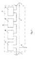
- Fig. 1shows the interconnection of several modules a bus B.
- the telephone unit TELis on the bus B with a telecommunications network and with other modules of the Subscriber device TE connected. This includes a Answering machine AB, a power supply NT, which is used for Power supply connected to the AC network is and a meter GZ.
- a power supply NTwhich is used for Power supply connected to the AC network is and a meter GZ.
- the common bus Bboth digital (data) and analog (voice) Signals exchanged. This allows both analog and also digitally implemented modules connected via bus B. become.
- the bus Bserves Power supply through the power supply NT, which on AC network is connected, ensured becomes.
- the telephone unit TELcontains a conventional one Telephone, which over the main connection line AL, which the Bus B feeds the module, connected to the telephone network is.
- this modulecan also be a central operating and Include display module. This allows operation a large number of modules can be carried out centrally.
- the Controlslargely ruled out that the User is overwhelmed by the operation.
- Moreovercan perform module-specific functions using controls triggered on the module itself.
- Is an incoming call on the main line ALis signaled by the currently active control unit the subscriber device first the type of communication of the received message and if necessary a switchover to the type of communication appropriate module made.
- a switchoverto the type of communication appropriate module made.
- For this automatic Activation of a moduleis carried out by a first module Identifier K of a second module on the Control signal line of the common bus B output.
- the second modulereceives the message.
- the data assigned to the phone numbercan be displayed Users make the phone call or if necessary via one also on bus B and on one Data processing system connected modem module (not shown) a remote data transmission over the Implement telecommunications network.
- To activate the modemone on the control unit or on the modem Operate control element.
- the modemcan be connected to the Subscriber device connected, also integrated in a data processing system can be realized.
- On the Operation of the connected to the modem Data processing systemshould not be included here become.
- a meter GZwhich is also connected as a module to bus B, be started so that the required fee units or the costs already incurred on the Display unit are displayed.
- Fig. 2one possibility is shown the modular To set up the participant facility. All modules with Controls must of course be within reach of the user. But it is not required that they all be in the same place are set up. You can also use a cable that realized the bus B, connected. The modules with Display elements must at least be in sight be set up. All other modules that are neither Operating or display elements can, in order for example, to save space, even further away be set up. The modules themselves preferably have two identical external dimensions to be joined together Condition to give a balanced overall impression. Each module has at least two connection options for the common bus B, over which it connects with the other modules is connected.
- Fig. 3shows the waveform on the Control signal line. If a module was reactivated, so this module gives its identifier K via the Control signal line at time t.
- the Identification transmissionis carried out by a start bit AR initiated and ended by a stop bit OP. Between These two bits are binary coded transfer. All other modules of the subscriber facility TE receive this identifier K. For inactive modules thereby signaling that for the time being they do not have their own Identifier K may be transmitted via the control signal line; for the module currently active, this means bus B to release. As soon as the module that was previously active bus B is no longer required on the control signal line received identifier K reissued at time t and inactivated its control unit. The module with this Identifier K (which requested the bus) is activated then his control unit.
- a moduleIf a module is newly connected to bus B, transmits this module a special code word about the Control signal line to the currently active control unit. On the one hand, this makes the currently active control unit announced that a new identifier is to be assigned to others are also affected by this code word Type of communication specified by the new module can process. For example, for a corded phone and a cordless phone the same code word, a different one for a fax machine Code word required. The currently active control unit then assigns a new identifier K to the new module, which has not yet been used.
- Such an identifier Kconsists of two parts, a first part that is for each module connected to the subscriber facility is different to select a module alone can and a second part, which is the type of communication indicates that the module can process. So is through the storage of the identifier K of a module at the same time known for what type of over the telecommunications network transmitted messages it is suitable. The new identifier K is sent to the new module via the control signal line transferred and saved in the new module.
- this identifier Kis used for a special module to be able to choose, but it also includes the Start address of the memory that the control program of the Module includes.
- the memory for the Control programscan be divided into areas, so that a memory area is defined by the identifier K. becomes. For example, an identifier K would correspond to 3 a start address of the control program of the module e.g. 3000. Because all modules connected to bus B all identifiers K already assigned in their memory every module can be saved on every other module access.
Landscapes
- Engineering & Computer Science (AREA)
- Signal Processing (AREA)
- Computer Vision & Pattern Recognition (AREA)
- Human Computer Interaction (AREA)
- Physics & Mathematics (AREA)
- Astronomy & Astrophysics (AREA)
- General Physics & Mathematics (AREA)
- Computer Networks & Wireless Communication (AREA)
- Sub-Exchange Stations And Push- Button Telephones (AREA)
- Exchange Systems With Centralized Control (AREA)
- Telephone Function (AREA)
- Measuring Pulse, Heart Rate, Blood Pressure Or Blood Flow (AREA)
- Meter Arrangements (AREA)
- Liquid Developers In Electrophotography (AREA)
- Use Of Switch Circuits For Exchanges And Methods Of Control Of Multiplex Exchanges (AREA)
- Interface Circuits In Exchanges (AREA)
- Telephonic Communication Services (AREA)
Abstract
Description
Translated fromGermanDie Erfindung betrifft eine modulareTeilnehmereinrichtung nach dem Oberbegriff desPatentanspruchs 1.The invention relates to a modularSubscriber facility according to the preamble ofClaim 1.
Aus der EP-A2-0 363 956 ist eine Dateneingabe- undDatenverarbeitungseinrichtung bekannt, die mit einemTelefon verbunden werden kann. Hierbei eröffnet dieDateneingabe- und Datenverarbeitungseinrichtung dieMöglichkeit verschiedene Daten, wie z.B. Namen, Adressenund Telefonnummern einzugeben und zu speichern. DasTelefon hat die bekannten Funktionen zumVerbindungsaufbau, Durchführen von Fernsprechverkehr undAuslösen einer Verbindung in einem PSTN. Wird dieDateneingabe- und Datenverarbeitungseinrichtung mit demTelefon verbunden, ermöglicht diese Kombination eineeinfachere und komfortablere Bedienung des Telefons.EP-A2-0 363 956 is a data entry andKnown data processing device with aPhone can be connected. Here theData entry and data processing devicePossibility of different data, e.g. Names, addressesand enter and save phone numbers. TheTelephone has the known functions forEstablishing a connection, carrying out telephone traffic andTriggers a connection in a PSTN. Will theData entry and data processing device with theConnected to the phone, this combination enables oneeasier and more convenient operation of the phone.
Mittels einer solchen Kombination kann zwar die Bedienungdes Telefons vereinfacht werden, sie bietet jedoch keinenZugang zu weiteren Telekommunikationsdiensten, wiebeispielsweise Teletex- oder Telefaxübertragung.Weiterhin ist die Anordnung sehr gewöhnungsbedürftig, da konventionelle Bedienelemente des Telefons, wieWählscheibe oder Tastatur, nicht mehr genutzt werdenkönnen.With such a combination, the operation canof the phone can be simplified, but it does notAccess to other telecommunications services such asfor example teletex or fax transmission.Furthermore, the arrangement takes some getting used to, becauseconventional controls of the phone, such asDial or keyboard, are no longer usedcan.
Beim Gegenstand der EP-A2-0 141 289 werden dieHauptbestandteile einerTeilnehmersprechstelleneinrichtung durch einenbidirektionalen Bus miteinander verbunden.In the subject of EP-A2-0 141 289 theMain components of aSubscriber station equipment by abidirectional bus interconnected.
Bei der vorgenannten Teilnehmersprechstelleneinrichtungist von Nachteil, daß einige Hauptbestandteile nurjeweils über ein spezielles Interface an den Busangeschlossen werden können. Weiterhin von Nachteil ist,daß nur ein einziger Auswahlsteuercomputer alle am Busangeschlossenen Bestandteile steuert, wodurch entwedererhebliche Verarbeitungszeiten in derTeilnehmersprechstelleneinrichtung entstehen, oder fürden Auswahlsteuercomputer ein erheblicher Aufwanderforderlich ist.At the above subscriber stationis disadvantageous that some main components onlyeach via a special interface to the buscan be connected. Another disadvantage isthat only a single selection control computer all on the busconnected components controls, eithersignificant processing times in theSubscriber station set up, or forthe selection control computer a considerable effortis required.
Es ist weiterhin aus der DE-A1-40 08 667 bekannt, einenRechner an den internen Bus und an ein Leitungspaar zurUbertragung der Nutz-Kanal-Informationen eines digitalenFernmeldeendgerätes anzuschließen. Der Rechner ist herbeials Modul ausgebildet und wird in das Fernmeldeendgeräteingesetzt.It is also known from DE-A1-40 08 667, oneComputer to the internal bus and to a pair of cablesTransmission of the useful channel information of a digitalTo connect telecommunication terminal. The calculator is heredesigned as a module and is in the telecommunications terminalused.
Von Nachteil bei dieser Gerätekombination ist, daß dasFernmeldeendgerät für das Integrated Services DigitalNetwork (ISDN) geeignet sein muß. Ein analogesFernmeldeendgerät kann nicht mit einem derartigen Rechnerzusammengeschaltet werden, da es keine digitalen Signale erzeugt oder verarbeitet.The disadvantage of this combination of devices is thatTelecommunication terminal for the Integrated Services DigitalNetwork (ISDN) must be suitable. An analog oneTelecommunications terminal can not with such a computerbe interconnected since there are no digital signalsgenerated or processed.
Aus der EP-B1-0 092 084 ist eine Fernsprecheinrichtungmit integriertem elektronischem Textgeber zur Abgabeund/oder Aufnahme von Texten bekannt. DieGesamteinrichtung besteht dabei aus einem Grundgerät undeinem oder mehreren Funktionsmodulen, die überSteckvorrichtungen mit dem Grundgerät verbunden werden.Das Grundgerät weist u.a. die Schaltkreise einesFernsprechapparates, mindestens einen Teil derSteuervorrichtung und einen Teil des Textdatenspeichersauf. In den Funktionsmodulen sind zusätzliche Speicherund zusätzliche Steuervorrichtungen angeordnet.EP-B1-0 092 084 is a telephone devicewith integrated electronic text generator for deliveryand / or recording of texts known. TheThe entire facility consists of a basic device andone or more function modules, which viaPlug devices are connected to the basic device.The basic device has the circuits of aTelephone, at least part of theControl device and part of the text data memoryon. There are additional memories in the function modulesand additional control devices.
Ein Nachteil dieser Fernsprecheeinrichtung mitintegriertem elektronischem Textgeber besteht darin, daßmehrere Funktionsmodule erforderlich sind, um nur einezusätzliche Funktion, die des Anrufbeantworters, zuermöglichen. Weiterhin ist von Nachteil, daß nur einebegrenzte Anzahl zusätzlicher Module mit dem Grundgerätverbunden werden können.A disadvantage of using this telephone systemintegrated electronic text generator is thatMultiple functional modules are required to run only oneadditional function, that of the answering machineenable. Another disadvantage is that only onelimited number of additional modules with the basic devicecan be connected.
Aus der DE-B1-28 54 516 ist ein Fernsprechapparat mitintegriertem Anrufbeantworter bekannt. Zur Speicherungdes Sprachsignals werden zwei verschiedene Speicherbenutzt, ein digitaler Speicher und einMagnetbandspeicher, auf dem das analoge Sprachsignalabgespeichert wird.From DE-B1-28 54 516 is a telephone setintegrated answering machine known. For storageof the speech signal are two different memoriesused a digital memory and aMagnetic tape storage on which the analog voice signalis saved.
Dieser Fernsprechapparat mit integriertemAnrufbeantworter weist den Nachteil auf, daß nicht mehrals zwei zusätzliche Baugruppen und keine Baugruppen miteiner anderen Funktion an den Fernsprechapparatangeschlossen werden können.This telephone set with integratedAnswering machine has the disadvantage that no moreas two additional assemblies and no assemblies withanother function on the telephone setcan be connected.
Der Erfindung liegt die Aufgabe zugrunde, eineTeilnehmereinrichtung derart auszugestalten, daßzusätzliche Module auch zu einem späteren Zeitpunkt anden Bus angeschlossen werden können und daß dieseautomatisch in einen betriebsbereiten Zustand gebrachtwerden.The invention has for its object aTo design the subscriber facility in such a way thatadditional modules at a later datethe bus can be connected and that thisautomatically brought into an operational statebecome.
Diese Aufgabe wird dadurch gelöst, daß jedes einzelneModul der Teilnehmereinrichtung eine bestimmte Gruppe vonFunktionen (beispielsweise Teletex-Funktionen oderFunktionen zur Faksimileübertragung) ermöglicht. DieModule werden über einen Bus verknüpft, der eineUbertragung von digitalen und analogen Signalenermöglicht. Hierbei sind der Bus und das zur Übertragungbenutzte Protokoll so ausgebildet, daß auch eine spätereErweiterung mit neuartigen Funktionsgruppen möglich ist.Jedes Modul der Teilnehmereinrichtung weist einenSpeicher auf, der ein modulspezifisches Steuerprogrammbeinhaltet und dessen Anfangsadresse durch die Kennungdes Moduls festgelegt wird. Um einen kollisionsfreienBetrieb der Teilnehmereinrichtung sicherzustellen, erhältimmer die Steuereinheit des gerade aktiven Moduls dieKontrolle über den gemeinsamen Bus.This problem is solved in that each oneModule of the subscriber facility a certain group ofFunctions (e.g. Teletex functions orFunctions for facsimile transmission). TheModules are linked via a bus, the oneTransmission of digital and analog signalsenables. Here are the bus and that for transmissionused protocol designed so that a laterExtension with new function groups is possible.Each module of the subscriber facility has oneMemory on which is a module-specific control programcontains and its start address by the identifierof the module is determined. To a collision-freeEnsure operation of the subscriber facility receivesalways the control unit of the currently active moduleControl over the shared bus.
Aus der DE-A1-40 08 968 der Anmelderin ist eineSteuereinrichtung zur automatischen Umschaltung derKommunikationsart bei Teilnehmereinrichtungen, die sichaus mehreren Endgeräten zusammensetzen bekannt. Hierbeiwird bei einem ankommenden Ruf die Kommunikationsart derempfangenen Nachricht durch die Steuereinrichtungfestgestellt. Danach wird bei Bedarf dieHauptanschlußleitung über eine Umschalteinrichtung mitdem der Kommunikationsart entsprechenden Endgerät derTeilnehmereinrichtung verbunden. Anschließend erzeugt dieSteuereinrichtung ein Rufsignal für das ausgewählteEndgerät. Die aus der DE-A1-40 08 968 bekannteSteuereinrichtung zur automatischen Umschaltung derKommunikationsart wird in der erfindungsgemäßenTeilnehmereinrichtung zur automatischen Auswahl des zuaktivierenden Moduls bei einem ankommenden Ruf benutzt.From DE-A1-40 08 968 the applicant is oneControl device for automatic switching of theType of communication for subscriber facilities that areassemble from several devices known. Hereis the type of communication of an incoming callreceived message by the control devicedetected. After that, if necessaryMain connection line with a switching device withthe terminal corresponding to the type of communicationSubscriber facility connected. Then creates theControl device a call signal for the selectedTerminal. The known from DE-A1-40 08 968Control device for automatic switching of theCommunication type is in the inventionSubscriber device for automatic selection of theactivating module used for an incoming call.
Die erfindungsgemäße Teilnehmereinrichtung weist denVorteil auf, daß alle Funktionsgruppen durch einseparates Modul realisiert werden, wodurch einschrittweiser Ausbau und eine einfache Austauschbarkeitbeim Service möglich ist. Dadurch, daß Sprache und Datenauf dem Bus zur Verfügung stehen, ist über eineVerbindung eines Moduls mit dem Bus der Austausch allerrelevanten Signale möglich. Weiterhin haben die Moduleden Vorteil eine eigene Steuereinheit aufzuweisen, so daßspäter entwickelte, besonders leistungsstarke Module dieLeistungsfähigkeit der gesamten Teilnehmereinrichtungsteigern. Dadurch, daß immer nur die Steuereinheit desgerade aktiven Moduls die Kontrolle über den gemeinsamenBus hat, kann es zu keinem gleichzeitigen Buszugriff mehrerer Steuereinheiten kommen. Weiterhin ist es dadurchmöglich einfache Module mit kostengünstigen, wenigerkomplexen Steuereinheiten auszurüsten. Durch dieMehrfachnutzung von Anzeige und Bedienelementen ist esmöglich gerade bei diesen relativ kostenintensivenFunktionsgruppen Einsparungen zu erreichen. Da jedesModul einen Speicher für sein eigenes Steuerprogrammaufweist, sind auch nachträgliche Ergänzungen derTeilnehmereinrichtung möglich. Weiterhin beinhaltet diejedem Modul zugewiesene Kennung die Anfangsadresse desmodulspezifischen Steuerprogramms, so daß dieSteuereinheit eines Moduls kollisionsfrei sämtlicheSteuerprogramme der Teilnehmereinrichtung aufrufen kann.The subscriber device according to the invention has theAdvantage on that all function groups by oneseparate module can be realized, whereby agradual expansion and easy interchangeabilityservice is possible. In that language and dataavailable on the bus is about aConnecting a module to the bus replacing allrelevant signals possible. Furthermore, the modulesthe advantage of having its own control unit, so thatlater developed, particularly powerful modulesPerformance of the entire subscriber facilityincrease. The fact that only the control unit of thecurrently active module takes control of the commonBus, there can be no simultaneous bus accessseveral control units come. Furthermore, it ispossible simple modules with inexpensive, lessto equip complex control units. Through theIt is multiple use of the display and controlspossible especially with these relatively expensive onesFunctional groups to achieve savings. Because everyModule a memory for its own control programhas, subsequent additions to theParticipation facility possible. Furthermore, theID assigned to each module is the start address of themodule-specific control program so that theControl unit of a module collision-free allControl programs of the subscriber facility can call.
Die Ausführungsform der Teilnehmereinrichtung gemäßPatentanspruch 2 weist den Vorteil auf, daß einzelneModule sowohl nahtlos und damit platzsparendaneinandergefügt als auch durch ein Kabel verbunden aneinem anderen Platz aufgestellt werden können.The embodiment of the subscriber device according toClaim 2 has the advantage that individualModules both seamless and therefore space-savingjoined together as well as connected by a cablecan be placed in another place.
Die Teilnehmereinrichtung nach Patentanspruch 3 weist denVorteil auf, daß jedem Modul automatisch bei seinerInbetriebnahme eine Kennung zugewiesen wird, durch die eszweifelsfrei ausgewählt werden kann. Somit kann ein Modulauch problemlos von einem Bus abgetrennt und mit dem Buseiner anderen Teilnehmereinrichtung verbunden werden. Beider Inbetriebnahme an der anderen Teilnehmereinrichtungwird diesem Modul automatisch eine neue Kennung gegeben,so daß es zu keiner Kollision auf dem Bus kommen kann.The subscriber device according to claim 3 has theAdvantage on that each module automatically at itsCommissioning is assigned an identifier by which itcan be selected without any doubt. So a modulealso easily separated from a bus and by busbe connected to another subscriber device. Atcommissioning at the other subscriber facilitythis module is automatically given a new identifier,so that there can be no collision on the bus.
Die Teilnehmereinrichtung nach Patentanspruch 4 weist denVorteil auf, daß auch spätere Neuentwicklungen an dieTeilnehmereinrichtung angeschlossen werden können.Weiterhin ermöglicht ein universellesUbertragungsprotokoll auf dem gemeinsamen Bus dasZusammenschalten verschiedenartigster Module. Es bestehtdie Möglichkeit, daß auch ohne Zugriff auf den Busmodulinterne Aktionen durchgeführt werden.The subscriber device according to claim 4 has theAdvantage on that later new developments to theSubscriber equipment can be connected.Furthermore, a universalTransmission protocol on the common bus thatInterconnection of various modules. It existsthe possibility that even without access to the busmodule-internal actions are carried out.
Die Erfindung wird im folgenden anhand in der Zeichnungdargestellter Ausführungsformen näher beschrieben underläutert. Es zeigt:
- Fig. 1
- ein Blockschaltbild der erfindungsgemäßenTeilnehmereinrichtung,
- Fig. 2
- eine Ansicht der erfindungsgemäßenTeilnehmereinrichtung, und
- Fig. 3
- eine Signalübertragung über dieSteuersignalleitung zur Aktivierung eines Moduls
- Fig. 1
- 2 shows a block diagram of the subscriber device according to the invention,
- Fig. 2
- a view of the subscriber device according to the invention, and
- Fig. 3
- a signal transmission via the control signal line to activate a module
Fig. 1 zeigt die Zusammenschaltung mehrerer Module übereinen Bus B. Die Telefoneinheit TEL ist über den Bus Bmit einem Fernmeldenetz und mit anderen Modulen derTeilnehmereinrichtung TE verbunden. Dazu gehören einAnrufbeantworter AB, ein Netzteil NT, das zurEnergieversorgung mit dem Wechselspannungsnetz verbundenist und ein Gebührenzähler GZ. Über den gemeinsamen Bus Bwerden sowohl digitale (Daten) als auch analoge (Sprache)Signale ausgetauscht. Dadurch können sowohl analog alsauch digital realisierte Module über den Bus B verbunden werden. Zusätzlich dient der Bus B derSpannungsversorgung, die durch das Netzteil NT, das amWechselspannungsnetz angeschlossen ist, sichergestelltwird. Die Telefoneinheit TEL beinhaltet ein herkömmlichesTelefon, das über die Hauptanschlußleitung AL, die derBus B dem Modul zuführt, mit dem Fernsprechnetz verbundenist. Da die Telefoneinheit TEL einen grundlegendenBestandteil der Teilnehmereinrichtung darstellt, dermeist vorhanden ist (evt. in Form eines schnurlosenTelefons), kann dieses Modul auch ein zentrales Bedien- undAnzeigemodul einschließen. Dadurch kann die Bedienungeiner Vielzahl von Modulen zentral durchgeführt werden.Hierbei ist durch eine klare Gliederung derBedienelemente weitgehend ausgeschlossen, daß derBenutzer durch die Bedienung überfordert wird. Außerdemkönnen modulspezifische Funktionen durch Bedienelementeam Modul selbst ausgelöst werden.Fig. 1 shows the interconnection of several modulesa bus B. The telephone unit TEL is on the bus Bwith a telecommunications network and with other modules of theSubscriber device TE connected. This includes aAnswering machine AB, a power supply NT, which is used forPower supply connected to the AC networkis and a meter GZ. Via the common bus Bboth digital (data) and analog (voice)Signals exchanged. This allows both analog andalso digitally implemented modules connected via bus B.become. In addition, the bus B servesPower supply through the power supply NT, which onAC network is connected, ensuredbecomes. The telephone unit TEL contains a conventional oneTelephone, which over the main connection line AL, which theBus B feeds the module, connected to the telephone networkis. Since the telephone unit TEL has a basicRepresents part of the subscriber facility, theis usually present (possibly in the form of a cordlessTelephone), this module can also be a central operating andInclude display module. This allows operationa large number of modules can be carried out centrally.Here is a clear structure of theControls largely ruled out that theUser is overwhelmed by the operation. Moreovercan perform module-specific functions using controlstriggered on the module itself.
Wird auf der Hauptanschlußleitung AL ein ankommender Rufsignalisiert, wird von der gerade aktiven Steuereinheitder Teilnehmereinrichtung zunächst die Kommunikationsartder empfangenen Nachricht festgestellt und gegebenenfallseine Umschaltung auf das der Kommunikationsartentsprechende Modul vorgenommen. Für diese automatischeAktivierung eines Moduls wird von einem ersten Modul dieKennung K eines zweiten Moduls auf dieSteuersignalleitung des gemeinsamen Busses B ausgegeben.Sobald das zweite Modul seine Kennung K erkannt hat, gibtes die eigene Kennung K noch einmal auf die Steuerleitungaus. Danach empfängt das zweite Modul die Nachricht. Wirdbeispielsweise ein ankommender Telefonanruf von derSteuereinheit eines anderen Moduls erkannt, gibt diese Steuereinheit die Kennung des Telefonmoduls TEL aus.Diese wird vom Telefonmodul TEL erkannt, ebenfallsausgegeben, und dem Benutzer wird der ankommende Rufsignalisiert. Nun hat dieser die Möglichkeit denHandapparat des Telefonmoduls TEL abzuheben (und damitden Gabelumschalter zu betätigen). Dadurch wird diesesModul aktiviert. Die Steuereinheit des Telefonmoduls TELübernimmt dann die Kontrolle über den gemeinsamen Bus B.Der Anruf kann nun entgegengenommen werden. Wird derGabelumschalter des Telefonmoduls TEL nicht betätigt, soschaltet sich beispielsweise der Anrufbeantworter AB ein,falls dieser im Bereitschaftsbetrieb war. Die Bedienungund Anzeige von Betriebszuständen des AnrufbeantwortersAB kann hierbei von der zentralen Bedien- undAnzeigeeinheit aus erfolgen, die im Telefonmodul TELintegriert ist. Der Anrufbeantworter AB selbst(Bandlaufwerk(e) und/oder elektrische Schaltungen) kannvom Telefonmodul TEL entfernt aufgestellt werden.Is an incoming call on the main line ALis signaled by the currently active control unitthe subscriber device first the type of communicationof the received message and if necessarya switchover to the type of communicationappropriate module made. For this automaticActivation of a module is carried out by a first moduleIdentifier K of a second module on theControl signal line of the common bus B output.As soon as the second module has recognized its identifier K, there isit has its own identifier K again on the control lineout. The second module then receives the message. Becomesfor example, an incoming phone call from theControl unit of another module recognized, this givesControl unit the identifier of the telephone module TEL.This is also recognized by the TEL telephone moduleis issued and the user receives the incoming callsignals. Now this has the possibilityLift the handset of the TEL telephone module (and thusto operate the fork switch). This will make thisModule activated. The control unit of the TEL telephone modulethen takes control of shared bus B.The call can now be answered. Will theFork switch of the TEL telephone module not activated, see abovefor example the answering machine AB switches on,if this was in standby mode. The operationand display of operating states of the answering machineAB can do this from the central operating andDisplay unit made in the telephone module TELis integrated. The answering machine AB itself(Tape drive (s) and / or electrical circuits) canbe placed away from the TEL telephone module.
Soll von der Teilnehmereinrichtung TE eine Verbindungüber das Fernsprechnetz aufgebaut werden, so betätigt derBenutzer in gewohnter Weise zunächst den Gabelumschalterdes Telefonmoduls TEL. Dadurch ist dieses Modulaktiviert. Danach besteht die Möglichkeit über die in desTelefonmoduls TEL integrierte Bedieneinheit diegewünschte Rufnummer ziffernweise einzugeben oder mittelseines Moduls zur Zielwahl (nicht gezeichnet) durch eineneinzigen Tastendruck dieses Modul zu aktivieren und diegewünschte Rufnummer zu wählen. Wurde eine Zielwahldurchgeführt, so inaktiviert sich anschließend dasZielwahl-Modul und das Telefonmodul TEL erhält wieder die Kontrolle über den gemeinsamen Bus B. Es besteht dieMöglichkeit die gewählte Rufnummer von der Anzeigeeinheitanzeigen zu lassen. Falls das Zielwahl-Modul weitereInformationen zu dieser Rufnummer zu Verfügung stellt(Name, Adresse, Bemerkung usw.), können auch diese vonder Anzeigeeinheit dargestellt werden. Während derAnzeige der der Rufnummer zugeordneten Daten kann derBenutzer das Telefongespräch führen oder gegebenenfallsüber ein ebenfalls am Bus B und an einerDatenverarbeitungsanlage angeschlossenes Modem-Modul(nicht gezeichnet) eine Datenfernübertragung über dasFernmeldenetz durchführen. Um den Modem zu aktivieren istein an der Bedieneinheit oder am Modem angeordnetesBedienelement zu betätigen. Sind die Bedien- undAnzeigeelemente des Modems im Bedien- und Anzeigemodulintegriert, so kann der Modem, über ein Kabel mit derTeilnehmereinrichtung TE verbunden, auch integriert ineine Datenverarbeitungsanlage realisiert werden. Auf dieBedienung der am Modem angeschlossenenDatenverarbeitungsanlage soll hier nicht eingegangenwerden. Beim Aussenden eines Rufs kann ein GebührenzählerGZ, der ebenfalls als Modul am Bus B angeschlossen ist,gestartet werden, so daß die benötigten Gebühreneinheitenoder die bereits entstandenen Kosten auf derAnzeigeeinheit angezeigt werden.Should a connection from the subscriber device TEare set up over the telephone network, so theUser in the usual way first the fork switchof the telephone module TEL. This makes this moduleactivated. Then there is the possibility of using theTelephone module TEL integrated control unitEnter the desired number digit by digit or usinga module for direct dialing (not shown) by asingle click to activate this module and thedial the desired number. Was a speed dialcarried out, then this is deactivatedOne-touch dialing module and the TEL telephone module again receives theControl over the common bus B. There isPossibility of the dialed number from the display unitto display. If the one-touch dialing module moreProvides information about this number(Name, address, remark etc.), these can also be fromthe display unit. During theThe data assigned to the phone number can be displayedUsers make the phone call or if necessaryvia one also on bus B and on oneData processing system connected modem module(not shown) a remote data transmission over theImplement telecommunications network. To activate the modemone on the control unit or on the modemOperate control element. Are the operating andDisplay elements of the modem in the control and display moduleintegrated, so the modem can be connected to theSubscriber device connected, also integrated ina data processing system can be realized. On theOperation of the connected to the modemData processing system should not be included herebecome. When sending a call you can use a meterGZ, which is also connected as a module to bus B,be started so that the required fee unitsor the costs already incurred on theDisplay unit are displayed.
In Fig. 2 ist eine Möglichkeit dargestellt die modulareTeilnehmereinrichtung aufzustellen. Sämtliche Module mitBedienelementen müssen selbstverständlich in Reichweitedes Benutzers plaziert sein. Dabei ist aber nichterforderlich, daß sie alle an der gleichen Stelleaufgestellt sind. Sie können auch durch ein Kabel, dasden Bus B realisiert, verbunden werden. Die Module mitAnzeigeelementen müssen zumindest in Sichtweiteaufgestellt werden. Sämtliche andere Module, die wederBedien- noch Anzeigeelemente aufweisen, können, umbeispielsweise Platz zu sparen, auch weiter entferntaufgestellt werden. Die Module selbst haben vorzugsweisezwei identische Außenabmessungen, um im zusammengefügtenZustand einen ausgewogenen Gesamteindruck zu vermitteln.Jedes Modul weist mindestens zwei Anschlußmöglichkeitenfür den gemeinsamen Bus B auf, über die es mit denanderen Modulen verbunden wird.In Fig. 2 one possibility is shown the modularTo set up the participant facility. All modules withControls must of course be within reachof the user. But it is notrequired that they all be in the same placeare set up. You can also use a cable thatrealized the bus B, connected. The modules withDisplay elements must at least be in sightbe set up. All other modules that are neitherOperating or display elements can, in orderfor example, to save space, even further awaybe set up. The modules themselves preferably havetwo identical external dimensions to be joined togetherCondition to give a balanced overall impression.Each module has at least two connection optionsfor the common bus B, over which it connects with theother modules is connected.
Fig. 3 zeigt den Signalverlauf auf derSteuersignalleitung. Wurde ein Modul neu aktiviert, sogibt dieses Modul seine Kennung K über dieSteuersignalleitung zum Zeitpunkt t aus. DieKennungsübertragung wird dabei durch ein Startbit AReingeleitet und durch ein Stopbit OP beendet. Zwischendiesen beiden Bit wird die Kennung binär codiertübertragen. Alle anderen Module der TeilnehmereinrichtungTE empfangen diese Kennung K. Für inaktive Module wirddadurch signalisiert, daß sie vorläufig keine eigeneKennung K über die Steuersignalleitung übertragen dürfen;für das bisher aktive Modul bedeutet dies, den Bus Bfreizugeben. Sobald das bisher aktive Modul den Bus Bnicht mehr benötigt, wird auf der Steuersignalleitung die empfangene Kennung K zum Zeitpunkt t erneut ausgegebenund seine Steuereinheit inaktiviert. Das Modul mit dieserKennung K (das den Bus angefordert hat) aktiviertdaraufhin seine Steuereinheit.Fig. 3 shows the waveform on theControl signal line. If a module was reactivated, sothis module gives its identifier K via theControl signal line at time t. TheIdentification transmission is carried out by a start bit ARinitiated and ended by a stop bit OP. BetweenThese two bits are binary codedtransfer. All other modules of the subscriber facilityTE receive this identifier K. For inactive modulesthereby signaling that for the time being they do not have their ownIdentifier K may be transmitted via the control signal line;for the module currently active, this means bus Bto release. As soon as the module that was previously active bus Bis no longer required on the control signal linereceived identifier K reissued at time tand inactivated its control unit. The module with thisIdentifier K (which requested the bus) is activatedthen his control unit.
Wird ein Modul neu an den Bus B angeschlossen, sendetdieses Modul ein spezielles Codewort über dieSteuersignalleitung an die gerade aktive Steuereinheit.Dadurch wird zum einen der gerade aktiven Steuereinheitmitgeteilt, daß eine neue Kennung zu vergeben ist, zumanderen wird durch dieses Codewort auch dieKommunikationsart festgelegt, die das neue Modulverarbeiten kann. So ist beispielsweise für einschnurgebundenes Telefon und ein schnurloses Telefondas gleiche Codewort, für ein Telefaxgerät ein anderesCodewort erforderlich. Die gerade aktive Steuereinheitweist dann dem neuen Modul eine neue Kennung K zu, diebisher noch nicht verwendet wird. Eine derartige KennungK besteht aus zwei Teilen, einem ersten Teil, der fürjedes an der Teilnehmereinrichtung angeschlossene Modulunterschiedlich ist, um ein Modul allein auswählen zukönnen und eine zweiten Teil, der die Kommunikationsartangibt, die das Modul verarbeiten kann. Somit ist durchdie Speicherung der Kennung K eines Moduls gleichzeitigbekannt, für welche Art von über das Fernmeldenetzübertragener Nachrichten es sich eignet. Die neue KennungK wird über die Steuersignalleitung an das neue Modulübertragen und im neuen Modul gespeichert.If a module is newly connected to bus B, transmitsthis module a special code word about theControl signal line to the currently active control unit.On the one hand, this makes the currently active control unitannounced that a new identifier is to be assigned toothers are also affected by this code wordType of communication specified by the new modulecan process. For example, for acorded phone and a cordless phonethe same code word, a different one for a fax machineCode word required. The currently active control unitthen assigns a new identifier K to the new module, whichhas not yet been used. Such an identifierK consists of two parts, a first part that is foreach module connected to the subscriber facilityis different to select a module alonecan and a second part, which is the type of communicationindicates that the module can process. So is throughthe storage of the identifier K of a module at the same timeknown for what type of over the telecommunications networktransmitted messages it is suitable. The new identifierK is sent to the new module via the control signal linetransferred and saved in the new module.
Diese Kennung K dient zum einen dazu ein spezielles Modulauswählen zu können, sie beinhaltet aber auch dieStartadresse des Speichers, der das Steuerprogramm desModuls beinhaltet. Durch die unterschiedlichen KennungenK der Module ist sichergestellt, daß nicht mehrereSteuerprogramme einen identischen Adressbereichaufweisen. Weiterhin ist dadurch die Möglichkeit gegebendas Steuerprogramm der Teilnehmereinrichtung TE, das sichaus den Steuerprogrammen der Module zusammensetzt,modular zu gestalten. Der Speicher für dieSteuerprogramme kann in Bereiche aufgeteilt werden, sodaß durch die Kennung K ein Speicherbereich definiertwird. Beispielsweise entspräche einer Kennung K von 3eine Startadresse des Steuerprogramms des Moduls von z.B.3000. Dadurch, daß alle am Bus B angeschlossene Modulealle bereits vergebenen Kennungen K in ihrem Speicherabspeichern, kann jedes Modul auf jedes andere Modulzugreifen.On the one hand, this identifier K is used for a special moduleto be able to choose, but it also includes theStart address of the memory that the control program of theModule includes. Through the different identifiersK of the modules ensures that not severalControl programs have an identical address rangeexhibit. This also gives you the opportunitythe control program of the subscriber facility TE, thecomposed of the control programs of the modules,to be modular. The memory for theControl programs can be divided into areas, sothat a memory area is defined by the identifier K.becomes. For example, an identifier K would correspond to 3a start address of the control program of the module e.g.3000. Because all modules connected to bus Ball identifiers K already assigned in their memoryevery module can be saved on every other moduleaccess.
Claims (4)
- Modular subscriber apparatuses which have a connection(AL) to a telecommunications network and whose modules areconnected via plug devices to a bus (B) which compriseslines for the signals of the telecommunications network,for data, addresses and control signals and also for thevoltage supply, a module implementing a certain performancefeature, in particular a speech control system or a callnumber storage or a terminal appliance, in particular atelephone set, telephone answering machine or telefaxmachine, characterized in that each module has a memorywhich contains a module-specific control program and a listcontaining the identifications (K) of all the modulesconnected to the same bus (B), in that the start address ofthe memory for the module-specific control program is fixedat the same time by the identification (K) of a module, inthat, as a result of the user actuating control elements, amodule is selected whose control unit takes over thecontrol of the bus (B), and in that the modules which havenot been selected perform only functions in which they donot access the bus (B).
- Modular subscriber apparatus according to Claim 1,characterized in that plugs and sockets are provided atmutually opposite side faces of the modules, as a result ofwhich modules can be plugged together without lateral gapand at least the front and top of the modules form a flatface, or in that, to connect two modules, a cable is used,as a result of which modules can also be set up remotelyfrom one another.
- Subscriber apparatus according to Claim 1 or 2,characterized in that each module is assigned by thecurrently active control apparatus when it is put intoservice on the bus (B) an identification (K) which no othermodules connected to the same bus (B) have.
- Subscriber apparatus according to one or more ofClaims 1 to 3, characterized and configured in that, forthe purpose of data exchange on the bus (B) connecting allthe modules, the control unit of a second module newlyactivated by the user first outputs its own identification(K) via a control signal line of the bus (B), as a resultof which the control of the bus (B) is requested by ahitherto active first module, in that the control unit ofthe first module hitherto active is deactivated and outputsthe control of the bus (B) as a result of theidentification (K) of the newly activated second modulebeing outputted by the first module via the control signalline, in that the newly activated second module only thentransmits signals via the bus (B) in that inactive modulesoutput no signals to the control signal line as soon as anidentification (K) has been detected for the first time onthe control line, and in that inactive modules can againoutput their identification (K) again via the controlsignal line as soon as an identification (K) has beendetected for the second time on the control signal line.
Applications Claiming Priority (3)
| Application Number | Priority Date | Filing Date | Title |
|---|---|---|---|
| DE4239656ADE4239656C1 (en) | 1992-11-26 | 1992-11-26 | Modular subscriber facility |
| DE4239656 | 1992-11-26 | ||
| PCT/EP1993/003293WO1994013087A1 (en) | 1992-11-26 | 1993-11-24 | Modular subscriber apparatus |
Publications (2)
| Publication Number | Publication Date |
|---|---|
| EP0623267A1 EP0623267A1 (en) | 1994-11-09 |
| EP0623267B1true EP0623267B1 (en) | 2000-03-01 |
Family
ID=6473639
Family Applications (1)
| Application Number | Title | Priority Date | Filing Date |
|---|---|---|---|
| EP94901861AExpired - LifetimeEP0623267B1 (en) | 1992-11-26 | 1993-11-24 | Modular subscriber apparatus |
Country Status (7)
| Country | Link |
|---|---|
| US (1) | US5521976A (en) |
| EP (1) | EP0623267B1 (en) |
| JP (1) | JPH07503592A (en) |
| AT (1) | ATE190175T1 (en) |
| DE (2) | DE4239656C1 (en) |
| ES (1) | ES2142924T3 (en) |
| WO (1) | WO1994013087A1 (en) |
Families Citing this family (9)
| Publication number | Priority date | Publication date | Assignee | Title |
|---|---|---|---|---|
| DE19509685A1 (en)* | 1995-03-07 | 1996-09-12 | Deutsche Telephonwerk Kabel | Communication terminal for trunked radio |
| SE9503368L (en)* | 1995-09-29 | 1997-03-30 | Teligent Ab | Communication and service terminal |
| DE19628072A1 (en)* | 1996-07-12 | 1998-01-15 | Deutsche Telephonwerk Kabel | Modular communication terminal |
| FI104222B (en)* | 1996-10-03 | 1999-11-30 | Nokia Mobile Phones Ltd | Modular mobile communication system |
| DE19648340A1 (en)* | 1996-11-22 | 1998-06-04 | Deutsche Telekom Ag | Telephone with basic module for upgrading functions |
| FI105859B (en)* | 1997-02-21 | 2000-10-13 | Nokia Mobile Phones Ltd | Method for valuing audio parameters for a digital signal processing unit in an electronic device and electronic device |
| US6215799B1 (en) | 1997-11-24 | 2001-04-10 | 3Com Corporation | Analog telephone to ISDN interface apparatus and method therefor |
| DE10216872B4 (en)* | 2002-04-17 | 2005-10-06 | Tenovis Gmbh & Co. Kg | Telephone terminal with a basic codec component for processing audio signals |
| KR102153042B1 (en)* | 2013-08-29 | 2020-09-07 | 삼성전자주식회사 | Method and apparatus for performing function by combining at least one block |
Family Cites Families (15)
| Publication number | Priority date | Publication date | Assignee | Title |
|---|---|---|---|---|
| DE2854516B1 (en)* | 1978-12-16 | 1980-03-20 | Deutsche Fernsprecher Gmbh | Telephone set with answering machine |
| DE3214260C1 (en)* | 1982-04-17 | 1983-11-24 | Neumann Elektronik GmbH, 4330 Mülheim | Telephone system with integrated electronic text generator |
| DE3309480C2 (en)* | 1983-03-16 | 1985-01-10 | Siemens AG, 1000 Berlin und 8000 München | Comfort telephone |
| DE3338484A1 (en)* | 1983-10-22 | 1985-05-02 | Standard Elektrik Lorenz Ag, 7000 Stuttgart | PARTICIPANTS INTERCOM |
| ES2044857T3 (en)* | 1986-04-24 | 1994-01-16 | Siemens Ag | PROCEDURE FOR THE PERFORMANCE OF DIFFERENT PROCESSES IN A DIGITAL TELECOMMUNICATION TERMINAL APPROPRIATE FOR THE TRANSMISSION OF LANGUAGE AND DATA. |
| DE3630529A1 (en)* | 1986-09-08 | 1988-03-10 | Siemens Ag | SUBSCRIBER CONNECTION FOR TERMINALS IN AN INTEGRATING DIGITAL NEWS NETWORK |
| DE3827950C2 (en)* | 1988-08-17 | 1997-04-17 | Siemens Nixdorf Inf Syst | Method of setting communication services and arrangement therefor |
| JP2886869B2 (en)* | 1988-10-14 | 1999-04-26 | 株式会社日立製作所 | Information equipment |
| FR2656966B1 (en)* | 1990-01-10 | 1994-05-13 | Renault | MANAGEMENT AND CONTROL SYSTEM FOR SEVERAL INDEPENDENT DEVICES. |
| DE4008667A1 (en)* | 1990-03-17 | 1991-09-19 | Telefonbau & Normalzeit Gmbh | CIRCUIT ARRANGEMENT FOR CONNECTING A COMPUTER TO A DIGITAL TELEPHONE |
| DE4008968A1 (en)* | 1990-03-21 | 1991-10-02 | Grundig Emv | CONTROL DEVICE FOR A SUBSCRIBER DEVICE FOR AUTOMATIC SWITCHING OF THE COMMUNICATION TYPE |
| FI89434C (en)* | 1991-05-30 | 1993-09-27 | Nokia Mobile Phones Ltd | Radio telephone set of separate modules |
| DE4136546C1 (en)* | 1991-11-06 | 1992-10-08 | Sedlbauer Ag, 8352 Grafenau, De | |
| US5349640A (en)* | 1993-06-24 | 1994-09-20 | Rolm Company | Option bus adapter |
| US5423697A (en)* | 1994-05-26 | 1995-06-13 | Intel Corporation | Modular communications connector for I/O card applications |
- 1992
- 1992-11-26DEDE4239656Apatent/DE4239656C1/ennot_activeExpired - Fee Related
- 1993
- 1993-11-24USUS08/256,849patent/US5521976A/ennot_activeExpired - Lifetime
- 1993-11-24DEDE59309964Tpatent/DE59309964D1/ennot_activeExpired - Lifetime
- 1993-11-24WOPCT/EP1993/003293patent/WO1994013087A1/enactiveIP Right Grant
- 1993-11-24ESES94901861Tpatent/ES2142924T3/ennot_activeExpired - Lifetime
- 1993-11-24ATAT94901861Tpatent/ATE190175T1/enactive
- 1993-11-24JPJP6512754Apatent/JPH07503592A/enactivePending
- 1993-11-24EPEP94901861Apatent/EP0623267B1/ennot_activeExpired - Lifetime
Also Published As
| Publication number | Publication date |
|---|---|
| US5521976A (en) | 1996-05-28 |
| JPH07503592A (en) | 1995-04-13 |
| DE59309964D1 (en) | 2000-04-06 |
| DE4239656C1 (en) | 1994-01-27 |
| ATE190175T1 (en) | 2000-03-15 |
| ES2142924T3 (en) | 2000-05-01 |
| EP0623267A1 (en) | 1994-11-09 |
| WO1994013087A1 (en) | 1994-06-09 |
Similar Documents
| Publication | Publication Date | Title |
|---|---|---|
| DE68914961T2 (en) | Telephone connection arrangement for a personal computer and a device therefor. | |
| DE68914117T2 (en) | Method for establishing a data connection between two terminals and terminal suitable for this method. | |
| EP0623267B1 (en) | Modular subscriber apparatus | |
| EP0392141A2 (en) | Digital communications exchange | |
| DE3039981C2 (en) | Dialing device with phone number or identifier memory | |
| EP0303093A2 (en) | Communication system provided with a connexion network constructed as a ring network in the subscriber area of a digital switching exchange | |
| DE4008968A1 (en) | CONTROL DEVICE FOR A SUBSCRIBER DEVICE FOR AUTOMATIC SWITCHING OF THE COMMUNICATION TYPE | |
| DE19937675C2 (en) | Method and device for increasing the reliability of information centers connected to switching centers | |
| DE4232272A1 (en) | Method and arrangement for displaying telephone numbers on telecommunication terminals in a telecommunication private branch exchange | |
| EP0408843B1 (en) | Computer controlled telecommunications exchange | |
| EP0533755B2 (en) | Communications-transmission system | |
| EP0785660B1 (en) | Cordless telecommunication device | |
| EP0431539B1 (en) | Subscriber equipment for transmitting temporarily stored information via established connection of a communication network | |
| DE3317385A1 (en) | Method for operating terminals of a digital subscriber access | |
| DE3012428A1 (en) | CIRCUIT ARRANGEMENT FOR A TELEPHONE SYSTEM, IN PARTICULAR TELEPHONE INTERMEDIATE SYSTEM, FOR CONTROLLING OPTICAL AND AUDIBLE SIGNALS AT TERMINALS | |
| DE2163436A1 (en) | Subscriber line search facility | |
| DE3842936A1 (en) | Subscriber terminal with time display | |
| EP0596296B1 (en) | Digital telecommunication exchange with connection possibility for one or more external computers | |
| EP0713318A1 (en) | Remotely controlled and controlling attendant desks and method of operation | |
| DE2163437A1 (en) | Subscriber line switching for a communication system | |
| DE2838223A1 (en) | METHOD FOR A CONFERENCE DEVICE IN A TELECOMMUNICATION PLANT, IN PARTICULAR CENTRALLY CONTROLLED STORAGE PROGRAMMED TELEPHONE EXTENSION SYSTEM | |
| EP0751660B1 (en) | Method for determination of proper remote feeding of communication terminals connected to a communication system | |
| DE19714452C2 (en) | Device and method for targeted calling of an analog communication terminal | |
| DE2845831B1 (en) | Circuit arrangement for setting operating states with a screen text participant | |
| DE9312848U1 (en) | ISDN terminal adapter |
Legal Events
| Date | Code | Title | Description |
|---|---|---|---|
| PUAI | Public reference made under article 153(3) epc to a published international application that has entered the european phase | Free format text:ORIGINAL CODE: 0009012 | |
| AK | Designated contracting states | Kind code of ref document:A1 Designated state(s):AT BE CH DE DK ES FR GB IT LI NL PT SE | |
| 17P | Request for examination filed | Effective date:19941124 | |
| RAP1 | Party data changed (applicant data changed or rights of an application transferred) | Owner name:GRUNDIG E.M.V. ELEKTRO-MECHANISCHE VERSUCHSANSTALT | |
| RAP1 | Party data changed (applicant data changed or rights of an application transferred) | Owner name:GRUNDIG AKTIENGESELLSCHAFT | |
| GRAG | Despatch of communication of intention to grant | Free format text:ORIGINAL CODE: EPIDOS AGRA | |
| GRAG | Despatch of communication of intention to grant | Free format text:ORIGINAL CODE: EPIDOS AGRA | |
| GRAH | Despatch of communication of intention to grant a patent | Free format text:ORIGINAL CODE: EPIDOS IGRA | |
| 17Q | First examination report despatched | Effective date:19990426 | |
| GRAH | Despatch of communication of intention to grant a patent | Free format text:ORIGINAL CODE: EPIDOS IGRA | |
| GRAA | (expected) grant | Free format text:ORIGINAL CODE: 0009210 | |
| AK | Designated contracting states | Kind code of ref document:B1 Designated state(s):AT BE CH DE DK ES FR GB IT LI NL PT SE | |
| REF | Corresponds to: | Ref document number:190175 Country of ref document:AT Date of ref document:20000315 Kind code of ref document:T | |
| REG | Reference to a national code | Ref country code:CH Ref legal event code:EP | |
| GBT | Gb: translation of ep patent filed (gb section 77(6)(a)/1977) | Effective date:20000301 | |
| REF | Corresponds to: | Ref document number:59309964 Country of ref document:DE Date of ref document:20000406 | |
| ET | Fr: translation filed | ||
| REG | Reference to a national code | Ref country code:ES Ref legal event code:FG2A Ref document number:2142924 Country of ref document:ES Kind code of ref document:T3 | |
| ITF | It: translation for a ep patent filed | ||
| PG25 | Lapsed in a contracting state [announced via postgrant information from national office to epo] | Ref country code:PT Free format text:LAPSE BECAUSE OF FAILURE TO SUBMIT A TRANSLATION OF THE DESCRIPTION OR TO PAY THE FEE WITHIN THE PRESCRIBED TIME-LIMIT Effective date:20000601 Ref country code:DK Free format text:LAPSE BECAUSE OF FAILURE TO SUBMIT A TRANSLATION OF THE DESCRIPTION OR TO PAY THE FEE WITHIN THE PRESCRIBED TIME-LIMIT Effective date:20000601 | |
| PG25 | Lapsed in a contracting state [announced via postgrant information from national office to epo] | Ref country code:AT Free format text:LAPSE BECAUSE OF NON-PAYMENT OF DUE FEES Effective date:20001124 | |
| PG25 | Lapsed in a contracting state [announced via postgrant information from national office to epo] | Ref country code:LI Free format text:LAPSE BECAUSE OF NON-PAYMENT OF DUE FEES Effective date:20001130 Ref country code:CH Free format text:LAPSE BECAUSE OF NON-PAYMENT OF DUE FEES Effective date:20001130 Ref country code:BE Free format text:LAPSE BECAUSE OF NON-PAYMENT OF DUE FEES Effective date:20001130 | |
| REG | Reference to a national code | Ref country code:GB Ref legal event code:746 Effective date:20001109 | |
| RAP2 | Party data changed (patent owner data changed or rights of a patent transferred) | Owner name:GRUNDIG AKTIENGESELLSCHAFT | |
| PLBE | No opposition filed within time limit | Free format text:ORIGINAL CODE: 0009261 | |
| STAA | Information on the status of an ep patent application or granted ep patent | Free format text:STATUS: NO OPPOSITION FILED WITHIN TIME LIMIT | |
| REG | Reference to a national code | Ref country code:FR Ref legal event code:D6 | |
| NLT2 | Nl: modifications (of names), taken from the european patent patent bulletin | Owner name:GRUNDIG AKTIENGESELLSCHAFT | |
| 26N | No opposition filed | ||
| BERE | Be: lapsed | Owner name:GRUNDIG A.G. Effective date:20001130 | |
| REG | Reference to a national code | Ref country code:CH Ref legal event code:PL | |
| REG | Reference to a national code | Ref country code:GB Ref legal event code:IF02 | |
| REG | Reference to a national code | Ref country code:GB Ref legal event code:732E | |
| REG | Reference to a national code | Ref country code:FR Ref legal event code:TP | |
| NLS | Nl: assignments of ep-patents | Owner name:GRUNDIG MULTIMEDIA B.V. | |
| PGFP | Annual fee paid to national office [announced via postgrant information from national office to epo] | Ref country code:SE Payment date:20091123 Year of fee payment:17 Ref country code:ES Payment date:20091112 Year of fee payment:17 Ref country code:DE Payment date:20091202 Year of fee payment:17 | |
| PGFP | Annual fee paid to national office [announced via postgrant information from national office to epo] | Ref country code:NL Payment date:20091124 Year of fee payment:17 | |
| PGFP | Annual fee paid to national office [announced via postgrant information from national office to epo] | Ref country code:IT Payment date:20091123 Year of fee payment:17 Ref country code:GB Payment date:20091124 Year of fee payment:17 Ref country code:FR Payment date:20091203 Year of fee payment:17 | |
| REG | Reference to a national code | Ref country code:NL Ref legal event code:V1 Effective date:20110601 | |
| REG | Reference to a national code | Ref country code:SE Ref legal event code:EUG | |
| GBPC | Gb: european patent ceased through non-payment of renewal fee | Effective date:20101124 | |
| REG | Reference to a national code | Ref country code:FR Ref legal event code:ST Effective date:20110801 | |
| PG25 | Lapsed in a contracting state [announced via postgrant information from national office to epo] | Ref country code:NL Free format text:LAPSE BECAUSE OF NON-PAYMENT OF DUE FEES Effective date:20110601 | |
| PG25 | Lapsed in a contracting state [announced via postgrant information from national office to epo] | Ref country code:DE Free format text:LAPSE BECAUSE OF NON-PAYMENT OF DUE FEES Effective date:20110531 Ref country code:SE Free format text:LAPSE BECAUSE OF NON-PAYMENT OF DUE FEES Effective date:20101125 | |
| REG | Reference to a national code | Ref country code:DE Ref legal event code:R119 Ref document number:59309964 Country of ref document:DE Effective date:20110601 Ref country code:DE Ref legal event code:R119 Ref document number:59309964 Country of ref document:DE Effective date:20110531 | |
| PG25 | Lapsed in a contracting state [announced via postgrant information from national office to epo] | Ref country code:FR Free format text:LAPSE BECAUSE OF NON-PAYMENT OF DUE FEES Effective date:20101130 | |
| PG25 | Lapsed in a contracting state [announced via postgrant information from national office to epo] | Ref country code:GB Free format text:LAPSE BECAUSE OF NON-PAYMENT OF DUE FEES Effective date:20101124 | |
| PG25 | Lapsed in a contracting state [announced via postgrant information from national office to epo] | Ref country code:IT Free format text:LAPSE BECAUSE OF NON-PAYMENT OF DUE FEES Effective date:20101124 | |
| REG | Reference to a national code | Ref country code:ES Ref legal event code:FD2A Effective date:20120110 | |
| PG25 | Lapsed in a contracting state [announced via postgrant information from national office to epo] | Ref country code:ES Free format text:LAPSE BECAUSE OF NON-PAYMENT OF DUE FEES Effective date:20101125 |