EP0622871A2 - Prestressed shielding plates for electrical connectors - Google Patents
Prestressed shielding plates for electrical connectorsDownload PDFInfo
- Publication number
- EP0622871A2 EP0622871A2EP94301935AEP94301935AEP0622871A2EP 0622871 A2EP0622871 A2EP 0622871A2EP 94301935 AEP94301935 AEP 94301935AEP 94301935 AEP94301935 AEP 94301935AEP 0622871 A2EP0622871 A2EP 0622871A2
- Authority
- EP
- European Patent Office
- Prior art keywords
- shield
- connector
- terminal module
- contacts
- terminal
- Prior art date
- Legal status (The legal status is an assumption and is not a legal conclusion. Google has not performed a legal analysis and makes no representation as to the accuracy of the status listed.)
- Granted
Links
- 230000013011matingEffects0.000claimsdescription4
- 239000004020conductorSubstances0.000claimsdescription2
- 230000005489elastic deformationEffects0.000claimsdescription2
- 238000004519manufacturing processMethods0.000description4
- 230000005540biological transmissionEffects0.000description3
- 230000003247decreasing effectEffects0.000description2
- 230000002787reinforcementEffects0.000description2
- 230000000295complement effectEffects0.000description1
- 239000003989dielectric materialSubstances0.000description1
- 239000011810insulating materialSubstances0.000description1
- 239000000463materialSubstances0.000description1
- 239000002184metalSubstances0.000description1
- 238000000465mouldingMethods0.000description1
- 230000036316preloadEffects0.000description1
- 230000000284resting effectEffects0.000description1
- 230000008054signal transmissionEffects0.000description1
Images


Classifications
- H—ELECTRICITY
- H01—ELECTRIC ELEMENTS
- H01R—ELECTRICALLY-CONDUCTIVE CONNECTIONS; STRUCTURAL ASSOCIATIONS OF A PLURALITY OF MUTUALLY-INSULATED ELECTRICAL CONNECTING ELEMENTS; COUPLING DEVICES; CURRENT COLLECTORS
- H01R13/00—Details of coupling devices of the kinds covered by groups H01R12/70 or H01R24/00 - H01R33/00
- H01R13/646—Details of coupling devices of the kinds covered by groups H01R12/70 or H01R24/00 - H01R33/00 specially adapted for high-frequency, e.g. structures providing an impedance match or phase match
- H01R13/6461—Means for preventing cross-talk
- H01R13/6471—Means for preventing cross-talk by special arrangement of ground and signal conductors, e.g. GSGS [Ground-Signal-Ground-Signal]
- H—ELECTRICITY
- H01—ELECTRIC ELEMENTS
- H01R—ELECTRICALLY-CONDUCTIVE CONNECTIONS; STRUCTURAL ASSOCIATIONS OF A PLURALITY OF MUTUALLY-INSULATED ELECTRICAL CONNECTING ELEMENTS; COUPLING DEVICES; CURRENT COLLECTORS
- H01R13/00—Details of coupling devices of the kinds covered by groups H01R12/70 or H01R24/00 - H01R33/00
- H01R13/646—Details of coupling devices of the kinds covered by groups H01R12/70 or H01R24/00 - H01R33/00 specially adapted for high-frequency, e.g. structures providing an impedance match or phase match
- H01R13/6473—Impedance matching
- H01R13/6477—Impedance matching by variation of dielectric properties
Definitions
- This inventionrelates to shielding plates that are mountable to terminal modules of an electrical connector assembly, serving to shield columns of adjacent terminals from crosstalk.
- right angled connectorsfor electrical connection between two printed circuit boards or between a printed circuit board and conducting wires.
- the right angled connectortypically has a large plurality of pin receiving terminals and at right angles thereto, pins (for example compliant pins), that make electrical contact with a printed circuit board.
- Post headers on another printed circuit board or a post header connectorcan thus be plugged into the pin receiving terminals, making electrical contact therebetween.
- the transmission frequency of electrical signals through these connectorsis very high and requires not only balanced impedance of the various contacts within the terminal modules to reduce signal lag and reflection but also shielding between rows of terminals to reduce crosstalk.
- the object of this inventionis to provide a simple, cost effective shield for mounting between terminal modules of a right angled connector assembly.
- a further object of this inventionis to provide a shield that makes a reliable and effective electrical connection between a grounding circuit and the shield.
- Yet another object of this inventionis to provide a terminal module that can be assembled to a module housing with or without shielding, without requiring use of an insert or another terminal module.
- An object of this inventionhas been achieved by providing a right angle electrical connector assembly for mounting to a printed circuit board, comprising an insulating housing and at least one terminal module having a plurality of contacts of which a portion is encapsulated by an insulative web, characterized in that the connector has prestressed electrically conductive shields that can be mounted to and held against the terminal modules by elastic deformation of the shield in cooperation with shield mounting means of the module.
- Another object of this inventionhas been achieved by providing the aforementioned connector with a shield that is mounted substantially flush in a recess of the insulative web such that a plurality of modules can be assembled side by side with the insulative webs of adjacent modules contiguous.
- Yet another objecthas been achieved by providing the aforementioned connector with a shield prestressed pin for electrical contact with a terminal module grounding contact through a hole in the insulative web, the pin being integral and stamped from a base of the shield and comprising a resilient Y-shaped spring; and projections extending below the shield base make electrical contact with the printed circuit board.
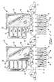
- a terminal module generally shown at 2is only partially manufactured having a plurality of edge stamped contacts generally shown at 4 which are shown still connected to a carrier strip 5, the terminal contacts 4 having a mating contact portion 6 for mating with pin contacts and a conductor connecting portion 8 for connection to a printed circuit board, interconnected by an intermediate portion 10.
- the portions 6, 8 and 10are formed from the same strip of sheet metal.
- an insulative web generally shown at 12is molded over the intermediate portions 10. Reinforcement strips 14 and 16 that help to support respectively contact portions 6 and 8, are maintained until after over-moulding of the insulative web 12 over the intermediate portions 10.
- the bridges 14 and reinforcement strip 16are then cut away, producing the terminal shown in Figure 10.
- Another manufacturing step required for completion of the terminal 2 of Figure 1is the twisting of adjacent pin receiving contacts 18 by approximately 90 degrees such that the contact surfaces 18 face each other for reception of a mating pin terminal.
- the terminal modules 2 of Figure 10 and 11are then inserted into the back of housing modules as disclosed in EP-A-0273589, whereby the pin receiving end 6 is for receiving a complementary male pin terminal and the pin terminal end 8 is for electrical contact with pin receiving holes of a printed circuit board.
- the insulative web 12 of the module 2When assembled to a housing and a printed circuit board, the insulative web 12 of the module 2 abuts on a forward surface 20 against the rear of the housing, and abuts the printed circuit board with surfaces 22.
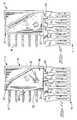
- the insulative over molded web 12is shown for better clarity without the contacts, comprising a top wall 24, a back wall 26, a front wall 28, a bottom wall 30 and an intermediate diagonal wall 32.
- the diagonal wall 32includes a recessed wall portion 33, which will be described more fully herein.
- the diagonal, front and bottom walls 32, 28, 30enclose an area in which the intermediate portions 10 of the contacts are encapsulated by the over-moulded dielectric material, whereby this over-moulded dielectric layer 36 is thinner than the walls 32, 30, 28 as shown in Figure 5, where A is the thickness of the encapsulated dielectric 36 and B the thickness of the wall 32.
- the difference between the thicknesses A and Bcreates two air pockets 40 on either side of the web 36 with thicknesses P1 and P2.
- the intermediate contact portions 10( Figure 1) have different lengths, the different lengths of the contacts mean that they have different impedances which is undesirable for high speed data transmission, this being explained in more detail in EP-A-0422785.
- the air pockets 40serve to decrease the dielectric constant between contacts, and match the impedance of the contacts 10 with respect to each other, for the same reasons as disclosed in the aforementioned document.
- the formeris done by displacing the contacts to the left (of Figure 1) such that the outer contacts 48, 50 have as direct a path as possible between portions 6 and 8, whereby intermediate portions 10 of contacts 42, 44 have to bend around in an approximately reversed C-shape from the portion 6 to the portion 8; and the latter is done by exposing a long intermediate portion 10, of the contact 50, to a pocket of air 40, the air having a lower dielectric constant than the material of the insulative web, whereby the inner contacts 42, 44 are exposed along a much shorter length to the pocket of air 40.
- the intermediate portions 10are not actually directly exposed to the pocket of air 40, but covered with a layer 36 of insulating material as this is easier to manufacture, protects, and provides better structural support for the intermediate portions 10. This does not however change the principal under which the air pocket affects the impedance of the contacts 42 to 50.
- the molded insulative web 12is shown comprising mounting holes 52 in the diagonal wall 32 and having interference fit protrusions 54 that extend from roughly halfway within the mounting through hole 52 to the end thereof as shown in Figure 3.
- the mounting holes 52receive tab mounts 56 of a shield 58 ( Figures 7,8), whereby the interference protrusions 54 cooperate with edges 57 of the mounts 56 for secure fastening of the shield 58 thereto.
- a grounding cavity 60 in the insulative web layer 36is provided to allow electrical contact of a resilient grounding pin 62 of the shield 58 ( Figure 7) with one of the contacts, namely contact 46 at an intermediate portion 10 (also see Figures 1, 5).
- the over-moulded insulative web 12also has a recess 66 ( Figure 4) defined by the contours 68, 69, 70 ( Figure 2) which has a thickness R essentially the same thickness as the shield 58.
- the shield outer contour 72, 73, 74( Figure 7) is substantially the same as, respectively, the interior contour formed by surfaces 68, 69, 70 of the insulative web 12 and can therefore be mounted to the web ( Figure 11) by means of the mounts 56 and corresponding mounting holes 52, such that the shield is within the recess 66 and the exterior surface flush to the exterior surface 71.
- the terminal modules 2can thus be assembled side by side to a housing module as described in EP-A-0422785 Figure 1 such that the walls 24, 26, 32 are contiguous to corresponding walls 24, 26, 32 of an adjacent terminal module 2.
- the shield 58has a planar base 76 defined by the contours 72, 73, 74 and 75, and as already mentioned, the base 76 of the shield 58 fits within the recess 66 of the over-moulded web 12, whereby the base 76 spans almost the entire surface of the contact intermediate portion 10 in order to provide a electrically conductive shield separating adjacent terminal modules 2 of a housing assembly.
- This interposed shieldingserves to limit unwanted crosstalk between contacts of adjacent terminal modules.
- Shielding elements interposed between adjacent terminal modulesis already known and disclosed for example in EP-A-0422785, whereby the shield element 180 disclosed therein performs substantially the same function as the shield of this present invention, but hasn't got the constructional advantages nor the effectiveness of the electrical grounding of the present invention as will be seen more clearly hereinafter.
- the shield 58will now be described in more detail with reference to Figures 7, 8 and 9.
- the mounts 56are inserted in an interference fit in the mounting holes 52 with the interference projections 54, the mounts 56 being bent at an angle F to the planar base whereas the mount can only be fully inserted into the mounting slot 52 by resiliently biasing the mounts 56 outwards by an angle H such that the mount forms an angle G (equal to F + H) with the planar base 76.
- the shield planar base 76is thus maintained resiliently against the walls 28 and 30 of the insulative web 12, which ensures that the planar base 76 is not only held securely against the over-moulded web 12 but also remains flush to the walls 24, 26, 32 and additionally ensures that the grounding pin 62 is firmly pressed against the contact 48 (through the cavity 60) in order to make good electrical contact therebetween, without lifting planar base 76 away from wall 28 and 30.
- the grounding pin 62is interconnected to the plate 76 by a root 63, which is proximate to the upper tabs 56.
- the grounding pin 62has a Y-shaped spring section 80 and a contact tip 82 for contacting the contact 48 as can be seen in Figure 9, the spring section 80 being inclined slightly inwards with respect to the planar base 76 in order to increase the resilient force with which the contact tip 81 is pressed against the contact 46.
- the Y-shape of the springprovides for a strong attachment of the spring to the base 76 and yet has the required flexibility due to the decreasing width towards the contact tip 81.
- the shield projections 84extend below the plan defined by the surfaces 22 of the molded web 12, the surfaces 22 resting against the printed circuit board surface when the module 2 is mounted thereon, thus resiliently biasing the shield contact arms 82 against the printed circuit board to make contact therewith.
- the grounding pin 62 and grounding arms 82act as an electrical "drain" between the shield and the common ground circuit of the various interconnected printed circuit boards and electrical devices whereby the effectiveness of this drain is determined by the length and resistance of the electrical path between the shield and ground circuit, by the number of electrical contacts therebetween, and by the optimal distribution of these contact points so as to cover the shield surface in the most evenly spread manner.
- the grounding pins 62, 82By having the two grounding arms 82 and the grounding pin 62, and by additionally having the grounding pins 62, 82 not only spread out but also as short and wide as possible (Y-shape) for a small electrical resistance and short electrical path to the shield, one provides a very effective drain between the shield and ground circuit.
- the movement of the tabs 56 through the angle Hcauses secure attachment of the crosstalk shield 58 to the molded web 12, as well as preloads the contact tip 82 against the intermediate contact 46.
- an intermediate mount 57that cooperates in an interference fit with an intermediate slot 53 of the moulded web 12, whereby the interference is provided by reducing the thickness of the slot with a ridge 55.
- This additional mounting means 57helps to fasten the prestressed shield 58 more securely against the moulded web 12.
- the preferred embodiment described abovemakes reference to shielding for right angled, impedance matched modular connectors for mounting to a printed circuit board.
- the inventionis not, however, limited to such connectors but also relates to advantageous shielding which may be applied to many different types of connectors and not only to those for mounting to a printed circuit board.
Landscapes
- Details Of Connecting Devices For Male And Female Coupling (AREA)
- Coupling Device And Connection With Printed Circuit (AREA)
- Connector Housings Or Holding Contact Members (AREA)
Abstract

Description
- This invention relates to shielding plates that are mountable to terminal modules of an electrical connector assembly, serving to shield columns of adjacent terminals from crosstalk.
- It is common, in the electronics industry, to use right angled connectors for electrical connection between two printed circuit boards or between a printed circuit board and conducting wires. The right angled connector typically has a large plurality of pin receiving terminals and at right angles thereto, pins (for example compliant pins), that make electrical contact with a printed circuit board. Post headers on another printed circuit board or a post header connector can thus be plugged into the pin receiving terminals, making electrical contact therebetween. The transmission frequency of electrical signals through these connectors is very high and requires not only balanced impedance of the various contacts within the terminal modules to reduce signal lag and reflection but also shielding between rows of terminals to reduce crosstalk.
- Impedance matching of terminal contacts has already been discussed in documents EP-A-0422785. Cost effective and simple designs of right angle connectors has also been discussed in EP-A-0422785, whereby the modular design makes it easy to produce shorter or longer connectors without redesigning and tooling up for a whole new connector, but only producing a new housing part into which a plurality of identical terminal modules are assembled. As shown in the aforementioned document, shielding members can be interposed between adjacent terminal modules. This requires however, either an insert to replace the shield or a thicker terminal module to take up the interposed shielding gap if the shielding is not required. The shielding disclosed in EP-A-0422785 has a pin receiving terminal end that is inserted into a housing module cavity, and a pin contact end for contacting the printed circuit board. This shield is relatively expensive to manufacture and assemble.
- With respect to the above mentioned disadvantages, the object of this invention is to provide a simple, cost effective shield for mounting between terminal modules of a right angled connector assembly.
- A further object of this invention, is to provide a shield that makes a reliable and effective electrical connection between a grounding circuit and the shield.
- Yet another object of this invention is to provide a terminal module that can be assembled to a module housing with or without shielding, without requiring use of an insert or another terminal module.
- An object of this invention has been achieved by providing a right angle electrical connector assembly for mounting to a printed circuit board, comprising an insulating housing and at least one terminal module having a plurality of contacts of which a portion is encapsulated by an insulative web, characterized in that the connector has prestressed electrically conductive shields that can be mounted to and held against the terminal modules by elastic deformation of the shield in cooperation with shield mounting means of the module.
- Another object of this invention has been achieved by providing the aforementioned connector with a shield that is mounted substantially flush in a recess of the insulative web such that a plurality of modules can be assembled side by side with the insulative webs of adjacent modules contiguous.
- Yet another object has been achieved by providing the aforementioned connector with a shield prestressed pin for electrical contact with a terminal module grounding contact through a hole in the insulative web, the pin being integral and stamped from a base of the shield and comprising a resilient Y-shaped spring; and projections extending below the shield base make electrical contact with the printed circuit board.
- The preferred embodiment of this invention will now be described by way of example with reference to the accompanying drawings in which:
- Figure 1 is a side view of partially stamped and formed terminal modules with over molded insulative webs, whereby phantom lines show the portion of the terminals that are encapsulated by the web;
- Figure 2 is a side view of the insulative web;
- Figure 3 is a view on the other side of the insulative web of Figure 2;
- Figure 4 is a view in the direction of arrow 4 in Figure 2;
- Figure 5 is a cross sectional view through lines 5-5 of Figure 2;
- Figure 6 is a cross sectional view through lines 6-6 of Figure 2;
- Figure 7 is a plan view of a shield that is attached to the insulative web of Figures 2, 3 and 4;
- Figure 8 is a view in the direction of
arrow 8 in Figure 7; - Figure 9 is a cross sectional view through lines 9-9 of Figure 7;
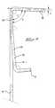
- Figure 10 is side view of a loose piece terminal module without shield;
- Figure 11 is a side view of a loose piece terminal module with a shield attached thereon.
- With reference to Figure 1, a terminal module generally shown at 2 is only partially manufactured having a plurality of edge stamped contacts generally shown at 4 which are shown still connected to a
carrier strip 5, the terminal contacts 4 having amating contact portion 6 for mating with pin contacts and aconductor connecting portion 8 for connection to a printed circuit board, interconnected by anintermediate portion 10. Theportions contact portions intermediate portions 10.Reinforcement strips portions insulative web 12 over theintermediate portions 10. During final manufacturing steps of theterminal module 2, thebridges 14 andreinforcement strip 16 are then cut away, producing the terminal shown in Figure 10. Another manufacturing step required for completion of theterminal 2 of Figure 1, is the twisting of adjacentpin receiving contacts 18 by approximately 90 degrees such that thecontact surfaces 18 face each other for reception of a mating pin terminal. - The
terminal modules 2 of Figure 10 and 11 are then inserted into the back of housing modules as disclosed in EP-A-0273589, whereby thepin receiving end 6 is for receiving a complementary male pin terminal and thepin terminal end 8 is for electrical contact with pin receiving holes of a printed circuit board. When assembled to a housing and a printed circuit board, theinsulative web 12 of themodule 2 abuts on aforward surface 20 against the rear of the housing, and abuts the printed circuit board withsurfaces 22. - With reference to Figures 2, 3 and 4, the insulative over molded
web 12 is shown for better clarity without the contacts, comprising atop wall 24, aback wall 26, afront wall 28, abottom wall 30 and an intermediatediagonal wall 32. Thediagonal wall 32 includes arecessed wall portion 33, which will be described more fully herein. The diagonal, front andbottom walls intermediate portions 10 of the contacts are encapsulated by the over-moulded dielectric material, whereby this over-mouldeddielectric layer 36 is thinner than thewalls wall 32. As shown in Figure 5 the difference between the thicknesses A and B creates twoair pockets 40 on either side of theweb 36 with thicknesses P1 and P2. Because of the right angled configuration of theterminal module 2, the intermediate contact portions 10 (Figure 1) have different lengths, the different lengths of the contacts mean that they have different impedances which is undesirable for high speed data transmission, this being explained in more detail in EP-A-0422785. Theair pockets 40 serve to decrease the dielectric constant between contacts, and match the impedance of thecontacts 10 with respect to each other, for the same reasons as disclosed in the aforementioned document. - Briefly resuming the latter: It is desirable to increase the speed of signal transmission in the
outer contacts inner contacts outer contacts outer contacts portions intermediate portions 10 ofcontacts portion 6 to theportion 8; and the latter is done by exposing a longintermediate portion 10, of thecontact 50, to a pocket ofair 40, the air having a lower dielectric constant than the material of the insulative web, whereby theinner contacts air 40. In the preferred embodiment, theintermediate portions 10 are not actually directly exposed to the pocket ofair 40, but covered with alayer 36 of insulating material as this is easier to manufacture, protects, and provides better structural support for theintermediate portions 10. This does not however change the principal under which the air pocket affects the impedance of thecontacts 42 to 50. - Once again referring to Figure 2, the molded
insulative web 12 is shown comprisingmounting holes 52 in thediagonal wall 32 and having interference fitprotrusions 54 that extend from roughly halfway within the mounting throughhole 52 to the end thereof as shown in Figure 3. Themounting holes 52 receivetab mounts 56 of a shield 58 (Figures 7,8), whereby theinterference protrusions 54 cooperate withedges 57 of themounts 56 for secure fastening of theshield 58 thereto. Agrounding cavity 60 in theinsulative web layer 36, is provided to allow electrical contact of aresilient grounding pin 62 of the shield 58 (Figure 7) with one of the contacts, namelycontact 46 at an intermediate portion 10 (also see Figures 1, 5). The over-mouldedinsulative web 12 also has a recess 66 (Figure 4) defined by thecontours shield 58. It should be noted in Figure 2, that thewalls planar surface 71, which is shown in both Figures 2 and 5. The shieldouter contour surfaces insulative web 12 and can therefore be mounted to the web (Figure 11) by means of themounts 56 andcorresponding mounting holes 52, such that the shield is within therecess 66 and the exterior surface flush to theexterior surface 71. Theterminal modules 2 can thus be assembled side by side to a housing module as described in EP-A-0422785 Figure 1 such that thewalls corresponding walls adjacent terminal module 2. - As seen in Figure 7, the
shield 58 has aplanar base 76 defined by thecontours base 76 of theshield 58 fits within therecess 66 of the over-mouldedweb 12, whereby thebase 76 spans almost the entire surface of the contactintermediate portion 10 in order to provide a electrically conductive shield separatingadjacent terminal modules 2 of a housing assembly. This interposed shielding serves to limit unwanted crosstalk between contacts of adjacent terminal modules. Shielding elements interposed between adjacent terminal modules is already known and disclosed for example in EP-A-0422785, whereby the shield element 180 disclosed therein performs substantially the same function as the shield of this present invention, but hasn't got the constructional advantages nor the effectiveness of the electrical grounding of the present invention as will be seen more clearly hereinafter. - The
shield 58 will now be described in more detail with reference to Figures 7, 8 and 9. As already mentioned themounts 56 are inserted in an interference fit in themounting holes 52 with theinterference projections 54, themounts 56 being bent at an angle F to the planar base whereas the mount can only be fully inserted into themounting slot 52 by resiliently biasing themounts 56 outwards by an angle H such that the mount forms an angle G (equal to F + H) with theplanar base 76. The shieldplanar base 76 is thus maintained resiliently against thewalls insulative web 12, which ensures that theplanar base 76 is not only held securely against the over-mouldedweb 12 but also remains flush to thewalls pin 62 is firmly pressed against the contact 48 (through the cavity 60) in order to make good electrical contact therebetween, without liftingplanar base 76 away fromwall grounding pin 62 is interconnected to theplate 76 by aroot 63, which is proximate to theupper tabs 56. Thus, when the tabs are inserted into theirrespective retaining openings 52, thetabs 56 and plate move through the angle H. This movement of thetabs 56 upwardly, causes thecontact 62 to rotate in the direction J, thereby further preloading thecontact tip 82 against the groundintermediate portion 46. Thegrounding pin 62 has a Y-shaped spring section 80 and acontact tip 82 for contacting thecontact 48 as can be seen in Figure 9, thespring section 80 being inclined slightly inwards with respect to theplanar base 76 in order to increase the resilient force with which thecontact tip 81 is pressed against thecontact 46. The Y-shape of the spring provides for a strong attachment of the spring to thebase 76 and yet has the required flexibility due to the decreasing width towards thecontact tip 81. - Extending from the bottom 75 of the
planar base 76 are twoarms 82 andintegral contact projections 84 for making contact with grounding circuit traces of the printed circuit board. When theshield 58 is mounted to theterminal module 2, theshield projections 84 extend below the plan defined by thesurfaces 22 of the moldedweb 12, thesurfaces 22 resting against the printed circuit board surface when themodule 2 is mounted thereon, thus resiliently biasing theshield contact arms 82 against the printed circuit board to make contact therewith. - Advantageously, the
grounding pin 62 and groundingarms 82 act as an electrical "drain" between the shield and the common ground circuit of the various interconnected printed circuit boards and electrical devices whereby the effectiveness of this drain is determined by the length and resistance of the electrical path between the shield and ground circuit, by the number of electrical contacts therebetween, and by the optimal distribution of these contact points so as to cover the shield surface in the most evenly spread manner. By having the two groundingarms 82 and thegrounding pin 62, and by additionally having the grounding pins 62, 82 not only spread out but also as short and wide as possible (Y-shape) for a small electrical resistance and short electrical path to the shield, one provides a very effective drain between the shield and ground circuit. Further more, by providing thetabs 56 at an angle F with respect to theplate member 76, the movement of thetabs 56 through the angle H causes secure attachment of thecrosstalk shield 58 to the moldedweb 12, as well as preloads thecontact tip 82 against theintermediate contact 46. - Finally, between the
mounts 56 is anintermediate mount 57 that cooperates in an interference fit with anintermediate slot 53 of the mouldedweb 12, whereby the interference is provided by reducing the thickness of the slot with aridge 55. This additional mounting means 57 helps to fasten theprestressed shield 58 more securely against the mouldedweb 12. - The preferred embodiment described above makes reference to shielding for right angled, impedance matched modular connectors for mounting to a printed circuit board. The invention is not, however, limited to such connectors but also relates to advantageous shielding which may be applied to many different types of connectors and not only to those for mounting to a printed circuit board.
Claims (13)
- An electrical connector assembly comprising an insulating housing and assembled thereto a plurality terminal modules (2) and electrically conductive shields inserted between adjacent terminal modules (2), each terminal module (2) having a plurality of contacts (4), the terminal module (2) comprising a mating contact portion (6), a conductor connecting portion (8) and therebetween an intermediate portion (10), the connector assembly characterized in that the terminal module (2) has an insulative web (12) that encapsulates some or all of the intermediate portion (10); and the electrically conductive shield (58) has mounting means (56, 57) that are engageable with mounting means (52, 54) of the terminal module (2), the shield (58) being prestressed such that when mounted to the insulative web (12) by the means (52, 54, 56, 57) the shield is held resiliently against the terminal module (2) due to elastic deformation of the shield.
- The connector of claim 1 characterized in that the shield (58) has a substantially planar base (76) that forms an angle (F) with the shield mounting means (56, 57) when the shield (58) is not mounted to the terminal module (2), and the base (76) can be elastically bent by an angle (H) away from the mounting means (56, 57) such that the base (76) forms an angle (G) equal to (H) plus (F) therewith when the shield is mounted to the terminal module (2).
- The connector of claim 1 or 2 characterized in that the shield (58) has a substantially planar base (76) and at least one prestressed mount (56) that can be resiliently bent for mounting in a receiving slot (52) of the insulative web (12), such that the shield (58) is fixedly held to the terminal module (2) and the planar base (76) resiliently biased thereagainst.
- The connector of claim 3 characterized in that the shield (58) is fixedly held to the terminal module (2) by interference fit means (54, 55).
- The connector of claim 4 characterized in that the interference fit means (54) are protrusions (54) within the slots (52), the protrusions cooperating with edges (57) of the mounts (56).
- The connector of any of claims 1-5 characterized in that the shield (58) is mounted substantially flush in a recess (66) of the insulative web (12) such that a plurality of modules (2) can be assembled side by side with the insulative webs (12) of adjacent modules (2) contiguous.
- The connector of any of claims 1-6 characterized in that the shield (58) has a resilient prestressed grounding pin (62) for electrical contact with one of the terminal module contacts (46).
- The connector of claim 7 characterized in that the insulative web (12) has a hole (60) such that the grounding pin (62) electrically contacts one of the terminal module contacts (46) therethrough.
- The connector of claim 8 characterized in that the grounding pin (62) is integral and stamped from a planar base (76) of the shield (58) and comprises a Y-shaped spring section (80) with a contact tip (82) bent therefrom that is resiliently biased against the corresponding terminal module contact (46).
- The connector of any of claims 1-9 characterized in that the shield planar base (76) has at least one resilient arm (82) having a grounding projection (84) stamped therefrom and that extends to the printed circuit board to make electrical contact therewith when the module (2) is assembled thereto.
- The connector of claim 10 characterized in that the arm (82) and the grounding projection (84) is in the same plane as the base (76).
- The connector of claim 11 characterized in that the shield planar base has two resilient arms (82) with their corresponding grounding projections (84).
- The connector of any of claims 1-12 characterized in that the shield (58) has a roughly triangular shape that spans the portion of contacts (10) encapsulated by the insulative web (12).
Applications Claiming Priority (2)
| Application Number | Priority Date | Filing Date | Title |
|---|---|---|---|
| GB9307127 | 1993-04-06 | ||
| GB939307127AGB9307127D0 (en) | 1993-04-06 | 1993-04-06 | Prestressed shielding plates for electrical connectors |
Publications (3)
| Publication Number | Publication Date |
|---|---|
| EP0622871A2true EP0622871A2 (en) | 1994-11-02 |
| EP0622871A3 EP0622871A3 (en) | 1996-01-31 |
| EP0622871B1 EP0622871B1 (en) | 1999-02-10 |
Family
ID=10733393
Family Applications (1)
| Application Number | Title | Priority Date | Filing Date |
|---|---|---|---|
| EP94301935AExpired - LifetimeEP0622871B1 (en) | 1993-04-06 | 1994-03-18 | Electrical connector assembly having prestressed shielding plates |
Country Status (7)
| Country | Link |
|---|---|
| US (1) | US5496183A (en) |
| EP (1) | EP0622871B1 (en) |
| JP (1) | JP3412771B2 (en) |
| KR (1) | KR100330126B1 (en) |
| CN (1) | CN1074591C (en) |
| DE (1) | DE69416448T2 (en) |
| GB (1) | GB9307127D0 (en) |
Cited By (9)
| Publication number | Priority date | Publication date | Assignee | Title |
|---|---|---|---|---|
| WO1998011633A1 (en)* | 1996-09-11 | 1998-03-19 | The Whitaker Corporation | Connector assembly with shielded modules and method of making same |
| WO1998035408A1 (en)* | 1997-02-07 | 1998-08-13 | Teradyne, Inc. | High speed, high density electrical connector |
| US5993259A (en)* | 1997-02-07 | 1999-11-30 | Teradyne, Inc. | High speed, high density electrical connector |
| EP1018785A1 (en)* | 1999-01-08 | 2000-07-12 | FCI's Hertogenbosch BV | Shielded connector and method for manufacturing same |
| WO2001039332A1 (en)* | 1999-11-24 | 2001-05-31 | Teradyne, Inc. | Differential signal electrical connectors |
| EP1107366A3 (en)* | 1999-12-01 | 2001-12-05 | Molex Incorporated | Electrical connector assembly with heat dissipating terminals |
| US6503103B1 (en) | 1997-02-07 | 2003-01-07 | Teradyne, Inc. | Differential signal electrical connectors |
| EP1229608A3 (en)* | 2001-02-05 | 2003-09-24 | HARTING KGaA | Contact modul for a connector, in particular a card-edge connector |
| CN104871650A (en)* | 2013-01-15 | 2015-08-26 | 奇诺格有限责任公司 | Plasma treatment device comprising a roller mounted rotatably in handle housing |
Families Citing this family (133)
| Publication number | Priority date | Publication date | Assignee | Title |
|---|---|---|---|---|
| US5848903A (en)* | 1992-09-14 | 1998-12-15 | Melcher Ag | Flat pin connector for electronic circuit boards |
| US5702258A (en)* | 1996-03-28 | 1997-12-30 | Teradyne, Inc. | Electrical connector assembled from wafers |
| US5664968A (en)* | 1996-03-29 | 1997-09-09 | The Whitaker Corporation | Connector assembly with shielded modules |
| US5882214A (en)* | 1996-06-28 | 1999-03-16 | The Whitaker Corporation | Electrical connector with contact assembly |
| WO1998056077A1 (en)* | 1997-06-02 | 1998-12-10 | Berg Technology, Inc. | Electrical connector with formed area ground spring |
| ATE322091T1 (en) | 1997-07-29 | 2006-04-15 | Hybricon Corp | CROSSTALK AND SIGNAL TRANSMISSION CHARACTERISTICS IMPROVED CONNECTOR |
| US5975921A (en)* | 1997-10-10 | 1999-11-02 | Berg Technology, Inc. | High density connector system |
| US6129592A (en)* | 1997-11-04 | 2000-10-10 | The Whitaker Corporation | Connector assembly having terminal modules |
| US5896275A (en)* | 1997-12-01 | 1999-04-20 | Lucent Technologies Inc. | Ground and shield for a surface acoustic wave filter package |
| US5961355A (en)* | 1997-12-17 | 1999-10-05 | Berg Technology, Inc. | High density interstitial connector system |
| US6530790B1 (en)* | 1998-11-24 | 2003-03-11 | Teradyne, Inc. | Electrical connector |
| US6471547B1 (en) | 1999-06-01 | 2002-10-29 | John T. Venaleck | Electrical connector for high density signal interconnections and method of making the same |
| US6565387B2 (en) | 1999-06-30 | 2003-05-20 | Teradyne, Inc. | Modular electrical connector and connector system |
| US6210228B1 (en) | 1999-10-01 | 2001-04-03 | Molex Incorporated | Shielded electrical connector |
| US6200165B1 (en) | 1999-10-01 | 2001-03-13 | Molex Incorporated | Shielded electrical connector with a folded wall |
| NL1013740C2 (en) | 1999-12-03 | 2001-06-06 | Fci S Hertogenbosch B V | Shielded connector. |
| EP1256147A2 (en) | 2000-02-03 | 2002-11-13 | Teradyne, Inc. | High speed pressure mount connector |
| US6386924B2 (en) | 2000-03-31 | 2002-05-14 | Tyco Electronics Corporation | Connector assembly with stabilized modules |
| AU2002229469A1 (en)* | 2000-12-06 | 2002-06-18 | Ept Gmbh And Co. Kg | Connector |
| US6843657B2 (en) | 2001-01-12 | 2005-01-18 | Litton Systems Inc. | High speed, high density interconnect system for differential and single-ended transmission applications |
| US6979202B2 (en) | 2001-01-12 | 2005-12-27 | Litton Systems, Inc. | High-speed electrical connector |
| US6910897B2 (en) | 2001-01-12 | 2005-06-28 | Litton Systems, Inc. | Interconnection system |
| US6776629B2 (en)* | 2002-06-13 | 2004-08-17 | Fci Americas Technology, Inc. | Connector for mounting to mating connector, and shield therefor |
| US6638111B1 (en) | 2002-07-11 | 2003-10-28 | Molex Incorporated | Board mounted electrical connector with improved ground terminals |
| WO2005053102A2 (en)* | 2003-11-21 | 2005-06-09 | Ohio Associated Enterprises Llc | Cable assembly and method of making |
| JP3909769B2 (en) | 2004-01-09 | 2007-04-25 | 日本航空電子工業株式会社 | connector |
| US7285018B2 (en)* | 2004-06-23 | 2007-10-23 | Amphenol Corporation | Electrical connector incorporating passive circuit elements |
| US20050283974A1 (en)* | 2004-06-23 | 2005-12-29 | Richard Robert A | Methods of manufacturing an electrical connector incorporating passive circuit elements |
| US20090291593A1 (en)* | 2005-06-30 | 2009-11-26 | Prescott Atkinson | High frequency broadside-coupled electrical connector |
| EP1764873B1 (en)* | 2005-09-16 | 2009-07-08 | Siemens Aktiengesellschaft | Modular control equipment with terminal and function modules |
| US7326082B2 (en)* | 2005-11-21 | 2008-02-05 | Tyco Electronics Corporation | Electrical connector |
| US7384311B2 (en)* | 2006-02-27 | 2008-06-10 | Tyco Electronics Corporation | Electrical connector having contact modules with terminal exposing slots |
| CN100530856C (en)* | 2006-05-10 | 2009-08-19 | 日本航空电子工业株式会社 | Connector |
| US7753742B2 (en)* | 2006-08-02 | 2010-07-13 | Tyco Electronics Corporation | Electrical terminal having improved insertion characteristics and electrical connector for use therewith |
| US8142236B2 (en)* | 2006-08-02 | 2012-03-27 | Tyco Electronics Corporation | Electrical connector having improved density and routing characteristics and related methods |
| US7549897B2 (en)* | 2006-08-02 | 2009-06-23 | Tyco Electronics Corporation | Electrical connector having improved terminal configuration |
| US7591655B2 (en)* | 2006-08-02 | 2009-09-22 | Tyco Electronics Corporation | Electrical connector having improved electrical characteristics |
| US7670196B2 (en)* | 2006-08-02 | 2010-03-02 | Tyco Electronics Corporation | Electrical terminal having tactile feedback tip and electrical connector for use therewith |
| US7484989B2 (en)* | 2006-11-29 | 2009-02-03 | Ohio Associated Enterprises, Llc | Low friction cable assembly latch |
| US7410393B1 (en) | 2007-05-08 | 2008-08-12 | Tyco Electronics Corporation | Electrical connector with programmable lead frame |
| TWI347049B (en)* | 2007-06-04 | 2011-08-11 | Hon Hai Prec Ind Co Ltd | Electrical card connector |
| US7566247B2 (en)* | 2007-06-25 | 2009-07-28 | Tyco Electronics Corporation | Skew controlled leadframe for a contact module assembly |
| US7585186B2 (en)* | 2007-10-09 | 2009-09-08 | Tyco Electronics Corporation | Performance enhancing contact module assemblies |
| EP2240980A2 (en) | 2008-01-17 | 2010-10-20 | Amphenol Corporation | Electrical connector assembly |
| US7651374B2 (en)* | 2008-06-10 | 2010-01-26 | 3M Innovative Properties Company | System and method of surface mount electrical connection |
| US7744414B2 (en)* | 2008-07-08 | 2010-06-29 | 3M Innovative Properties Company | Carrier assembly and system configured to commonly ground a header |
| US7690946B2 (en)* | 2008-07-29 | 2010-04-06 | Tyco Electronics Corporation | Contact organizer for an electrical connector |
| US8366485B2 (en) | 2009-03-19 | 2013-02-05 | Fci Americas Technology Llc | Electrical connector having ribbed ground plate |
| US8231415B2 (en) | 2009-07-10 | 2012-07-31 | Fci Americas Technology Llc | High speed backplane connector with impedance modification and skew correction |
| US7909646B2 (en)* | 2009-08-10 | 2011-03-22 | 3M Innovative Properties Company | Electrical carrier assembly and system of electrical carrier assemblies |
| US7927144B2 (en)* | 2009-08-10 | 2011-04-19 | 3M Innovative Properties Company | Electrical connector with interlocking plates |
| US7997933B2 (en)* | 2009-08-10 | 2011-08-16 | 3M Innovative Properties Company | Electrical connector system |
| US7850489B1 (en) | 2009-08-10 | 2010-12-14 | 3M Innovative Properties Company | Electrical connector system |
| US8475177B2 (en)* | 2010-01-20 | 2013-07-02 | Ohio Associated Enterprises, Llc | Backplane cable interconnection |
| CN107069274B (en) | 2010-05-07 | 2020-08-18 | 安费诺有限公司 | High performance cable connector |
| US8382524B2 (en) | 2010-05-21 | 2013-02-26 | Amphenol Corporation | Electrical connector having thick film layers |
| US20110287663A1 (en) | 2010-05-21 | 2011-11-24 | Gailus Mark W | Electrical connector incorporating circuit elements |
| CN102651509B (en)* | 2011-02-25 | 2014-03-12 | 富士康(昆山)电脑接插件有限公司 | Electric connector |
| US8591257B2 (en) | 2011-11-17 | 2013-11-26 | Amphenol Corporation | Electrical connector having impedance matched intermediate connection points |
| EP2624034A1 (en) | 2012-01-31 | 2013-08-07 | Fci | Dismountable optical coupling device |
| CN103296547B (en)* | 2012-02-22 | 2015-08-12 | 富士康(昆山)电脑接插件有限公司 | Electric connector and electric coupler component |
| CN103296510B (en) | 2012-02-22 | 2015-11-25 | 富士康(昆山)电脑接插件有限公司 | The manufacture method of terminal module and terminal module |
| US8944831B2 (en) | 2012-04-13 | 2015-02-03 | Fci Americas Technology Llc | Electrical connector having ribbed ground plate with engagement members |
| USD718253S1 (en) | 2012-04-13 | 2014-11-25 | Fci Americas Technology Llc | Electrical cable connector |
| USD727268S1 (en) | 2012-04-13 | 2015-04-21 | Fci Americas Technology Llc | Vertical electrical connector |
| US9257778B2 (en) | 2012-04-13 | 2016-02-09 | Fci Americas Technology | High speed electrical connector |
| USD727852S1 (en) | 2012-04-13 | 2015-04-28 | Fci Americas Technology Llc | Ground shield for a right angle electrical connector |
| CN103378433A (en)* | 2012-04-28 | 2013-10-30 | 富士康(昆山)电脑接插件有限公司 | Terminal piece and manufacturing method of electrical connector with terminal piece and terminal piece |
| US9543703B2 (en) | 2012-07-11 | 2017-01-10 | Fci Americas Technology Llc | Electrical connector with reduced stack height |
| USD751507S1 (en) | 2012-07-11 | 2016-03-15 | Fci Americas Technology Llc | Electrical connector |
| US9240644B2 (en) | 2012-08-22 | 2016-01-19 | Amphenol Corporation | High-frequency electrical connector |
| US20140194004A1 (en)* | 2013-01-07 | 2014-07-10 | Tyco Electronics Corporation | Grounding structures for a receptacle assembly |
| USD745852S1 (en) | 2013-01-25 | 2015-12-22 | Fci Americas Technology Llc | Electrical connector |
| USD720698S1 (en) | 2013-03-15 | 2015-01-06 | Fci Americas Technology Llc | Electrical cable connector |
| US9362646B2 (en) | 2013-03-15 | 2016-06-07 | Amphenol Corporation | Mating interfaces for high speed high density electrical connector |
| CN115411547A (en) | 2014-01-22 | 2022-11-29 | 安费诺有限公司 | Electrical connector, subassembly, module, cable assembly, electrical assembly and circuit board |
| US9685736B2 (en) | 2014-11-12 | 2017-06-20 | Amphenol Corporation | Very high speed, high density electrical interconnection system with impedance control in mating region |
| US9807869B2 (en) | 2014-11-21 | 2017-10-31 | Amphenol Corporation | Mating backplane for high speed, high density electrical connector |
| CN108701922B (en) | 2015-07-07 | 2020-02-14 | Afci亚洲私人有限公司 | Electrical connector |
| TWI754439B (en) | 2015-07-23 | 2022-02-01 | 美商安芬諾Tcs公司 | Connector, method of manufacturing connector, extender module for connector, and electric system |
| CN109076700B (en) | 2016-03-08 | 2021-07-30 | 安费诺公司 | Backplane footprint for high-speed, high-density electrical connectors |
| US10201074B2 (en) | 2016-03-08 | 2019-02-05 | Amphenol Corporation | Backplane footprint for high speed, high density electrical connectors |
| WO2017201170A1 (en) | 2016-05-18 | 2017-11-23 | Amphenol Corporation | Controlled impedance edged coupled connectors |
| TWI746561B (en) | 2016-05-31 | 2021-11-21 | 美商安芬諾股份有限公司 | High performance cable termination |
| US9768558B1 (en)* | 2016-06-22 | 2017-09-19 | Te Connectivity Corporation | Electrical connector and ground structure configured to reduce electrical resonance |
| CN112151987B (en) | 2016-08-23 | 2022-12-30 | 安费诺有限公司 | Configurable high performance connector |
| CN110088985B (en) | 2016-10-19 | 2022-07-05 | 安费诺有限公司 | Flexible shield for ultra-high speed high density electrical interconnects |
| US10050363B2 (en)* | 2016-10-28 | 2018-08-14 | Dell Products L.P. | Vertical backplane connector |
| IT201700083986A1 (en)* | 2017-07-24 | 2019-01-24 | Bticino Spa | Cover plate and group of parts for wall mounting modular electrical devices |
| TWI788394B (en) | 2017-08-03 | 2023-01-01 | 美商安芬諾股份有限公司 | Cable assembly and method of manufacturing the same |
| CN114512840B (en) | 2017-10-30 | 2024-06-25 | 安费诺富加宜(亚洲)私人有限公司 | Low crosstalk card edge connector |
| JP6981859B2 (en) | 2017-11-28 | 2021-12-17 | タイコエレクトロニクスジャパン合同会社 | connector |
| US10601181B2 (en) | 2017-12-01 | 2020-03-24 | Amphenol East Asia Ltd. | Compact electrical connector |
| US10777921B2 (en) | 2017-12-06 | 2020-09-15 | Amphenol East Asia Ltd. | High speed card edge connector |
| US10665973B2 (en) | 2018-03-22 | 2020-05-26 | Amphenol Corporation | High density electrical connector |
| WO2019183065A1 (en) | 2018-03-23 | 2019-09-26 | Amphenol Corporation | Insulative support for very high speed electrical interconnection |
| WO2019195319A1 (en) | 2018-04-02 | 2019-10-10 | Ardent Concepts, Inc. | Controlled-impedance compliant cable termination |
| US11057995B2 (en) | 2018-06-11 | 2021-07-06 | Amphenol Corporation | Backplane footprint for high speed, high density electrical connectors |
| CN208862209U (en) | 2018-09-26 | 2019-05-14 | 安费诺东亚电子科技(深圳)有限公司 | A connector and its applied PCB board |
| CN113169484A (en) | 2018-10-09 | 2021-07-23 | 安费诺商用电子产品(成都)有限公司 | High density edge connector |
| TWM576774U (en) | 2018-11-15 | 2019-04-11 | 香港商安費諾(東亞)有限公司 | Metal case with anti-displacement structure and connector thereof |
| US10931062B2 (en) | 2018-11-21 | 2021-02-23 | Amphenol Corporation | High-frequency electrical connector |
| US11381015B2 (en) | 2018-12-21 | 2022-07-05 | Amphenol East Asia Ltd. | Robust, miniaturized card edge connector |
| WO2020154507A1 (en) | 2019-01-25 | 2020-07-30 | Fci Usa Llc | I/o connector configured for cable connection to a midboard |
| US11101611B2 (en) | 2019-01-25 | 2021-08-24 | Fci Usa Llc | I/O connector configured for cabled connection to the midboard |
| US11189971B2 (en) | 2019-02-14 | 2021-11-30 | Amphenol East Asia Ltd. | Robust, high-frequency electrical connector |
| CN111585098B (en) | 2019-02-19 | 2025-08-19 | 安费诺有限公司 | High-speed connector |
| WO2020172395A1 (en) | 2019-02-22 | 2020-08-27 | Amphenol Corporation | High performance cable connector assembly |
| TWM582251U (en) | 2019-04-22 | 2019-08-11 | 香港商安費諾(東亞)有限公司 | Connector set with hidden locking mechanism and socket connector thereof |
| TW202448032A (en) | 2019-05-20 | 2024-12-01 | 美商安芬諾股份有限公司 | Connector module, connector, electronic assembly, electrical connector and wafer of connector module |
| CN114788097A (en) | 2019-09-19 | 2022-07-22 | 安费诺有限公司 | High speed electronic system with midplane cable connector |
| US11799230B2 (en) | 2019-11-06 | 2023-10-24 | Amphenol East Asia Ltd. | High-frequency electrical connector with in interlocking segments |
| US11588277B2 (en) | 2019-11-06 | 2023-02-21 | Amphenol East Asia Ltd. | High-frequency electrical connector with lossy member |
| WO2021154813A1 (en) | 2020-01-27 | 2021-08-05 | Amphenol Corporation | Electrical connector with high speed mounting interface |
| TWI887339B (en) | 2020-01-27 | 2025-06-21 | 美商Fci美國有限責任公司 | High speed, high density direct mate orthogonal connector |
| WO2021154702A1 (en) | 2020-01-27 | 2021-08-05 | Fci Usa Llc | High speed connector |
| CN115298912B (en) | 2020-01-27 | 2025-05-13 | 安费诺有限公司 | Electrical connector with high-speed mounting interface |
| CN113258325A (en) | 2020-01-28 | 2021-08-13 | 富加宜(美国)有限责任公司 | High-frequency middle plate connector |
| US11637391B2 (en) | 2020-03-13 | 2023-04-25 | Amphenol Commercial Products (Chengdu) Co., Ltd. | Card edge connector with strength member, and circuit board assembly |
| US11728585B2 (en) | 2020-06-17 | 2023-08-15 | Amphenol East Asia Ltd. | Compact electrical connector with shell bounding spaces for receiving mating protrusions |
| US11831092B2 (en) | 2020-07-28 | 2023-11-28 | Amphenol East Asia Ltd. | Compact electrical connector |
| US11652307B2 (en) | 2020-08-20 | 2023-05-16 | Amphenol East Asia Electronic Technology (Shenzhen) Co., Ltd. | High speed connector |
| CN212874843U (en) | 2020-08-31 | 2021-04-02 | 安费诺商用电子产品(成都)有限公司 | Electrical connector |
| CN215816516U (en) | 2020-09-22 | 2022-02-11 | 安费诺商用电子产品(成都)有限公司 | Electrical connector |
| CN213636403U (en) | 2020-09-25 | 2021-07-06 | 安费诺商用电子产品(成都)有限公司 | Electrical connector |
| CN112909607B (en)* | 2021-02-20 | 2023-09-01 | 中航光电科技股份有限公司 | Molding method of connector, shield sheet, ground contact piece and socket |
| US11569613B2 (en) | 2021-04-19 | 2023-01-31 | Amphenol East Asia Ltd. | Electrical connector having symmetrical docking holes |
| US12176650B2 (en) | 2021-05-05 | 2024-12-24 | Amphenol East Asia Limited (Hong Kong) | Electrical connector with guiding structure and mating groove and method of connecting electrical connector |
| CN215266741U (en) | 2021-08-13 | 2021-12-21 | 安费诺商用电子产品(成都)有限公司 | High-performance card connector meeting high-bandwidth transmission |
| CN113937569B (en)* | 2021-09-08 | 2024-07-30 | 中航光电科技股份有限公司 | Connector with conductive supporting structure terminal module |
| USD1002553S1 (en) | 2021-11-03 | 2023-10-24 | Amphenol Corporation | Gasket for connector |
| USD1067191S1 (en) | 2021-12-14 | 2025-03-18 | Amphenol Corporation | Electrical connector |
| USD1068685S1 (en) | 2021-12-14 | 2025-04-01 | Amphenol Corporation | Electrical connector |
Family Cites Families (13)
| Publication number | Priority date | Publication date | Assignee | Title |
|---|---|---|---|---|
| US4705332A (en)* | 1985-08-05 | 1987-11-10 | Criton Technologies | High density, controlled impedance connectors |
| US4715830A (en)* | 1986-10-27 | 1987-12-29 | Porta Systems Corp. | Wire strain relief and conductor retainer construction for telephone blocks |
| US4836791A (en)* | 1987-11-16 | 1989-06-06 | Amp Incorporated | High density coax connector |
| US4846727A (en)* | 1988-04-11 | 1989-07-11 | Amp Incorporated | Reference conductor for improving signal integrity in electrical connectors |
| ES2008808A6 (en)* | 1988-08-09 | 1989-08-01 | Amp Espanola | Modular jack assembly. |
| US4975084A (en)* | 1988-10-17 | 1990-12-04 | Amp Incorporated | Electrical connector system |
| ES2070283T3 (en)* | 1989-10-10 | 1995-06-01 | Whitaker Corp | CONTRAPLANE CONNECTOR WITH ADAPTED IMPEDANCES. |
| GB8928777D0 (en)* | 1989-12-20 | 1990-02-28 | Amp Holland | Sheilded backplane connector |
| US5046960A (en)* | 1990-12-20 | 1991-09-10 | Amp Incorporated | High density connector system |
| US5147218A (en)* | 1991-04-12 | 1992-09-15 | Minnesota Mining And Manufacturing Company | Pluggable modular splicing connector and bridging adapter |
| US5207597A (en)* | 1991-06-21 | 1993-05-04 | Amp Incorporated | Shielded connector with dual cantilever panel grounding beam |
| JP2513945Y2 (en)* | 1991-06-26 | 1996-10-09 | ホシデン株式会社 | connector |
| GB9205088D0 (en)* | 1992-03-09 | 1992-04-22 | Amp Holland | Shielded back plane connector |
- 1993
- 1993-04-06GBGB939307127Apatent/GB9307127D0/enactivePending
- 1994
- 1994-03-15USUS08/213,275patent/US5496183A/ennot_activeExpired - Lifetime
- 1994-03-18DEDE69416448Tpatent/DE69416448T2/ennot_activeExpired - Lifetime
- 1994-03-18EPEP94301935Apatent/EP0622871B1/ennot_activeExpired - Lifetime
- 1994-03-31CNCN94103109Apatent/CN1074591C/ennot_activeExpired - Lifetime
- 1994-04-01KRKR1019940006915Apatent/KR100330126B1/ennot_activeExpired - Lifetime
- 1994-04-06JPJP09307394Apatent/JP3412771B2/ennot_activeExpired - Lifetime
Cited By (14)
| Publication number | Priority date | Publication date | Assignee | Title |
|---|---|---|---|---|
| WO1998011633A1 (en)* | 1996-09-11 | 1998-03-19 | The Whitaker Corporation | Connector assembly with shielded modules and method of making same |
| WO1998035408A1 (en)* | 1997-02-07 | 1998-08-13 | Teradyne, Inc. | High speed, high density electrical connector |
| US5980321A (en)* | 1997-02-07 | 1999-11-09 | Teradyne, Inc. | High speed, high density electrical connector |
| US5993259A (en)* | 1997-02-07 | 1999-11-30 | Teradyne, Inc. | High speed, high density electrical connector |
| US6503103B1 (en) | 1997-02-07 | 2003-01-07 | Teradyne, Inc. | Differential signal electrical connectors |
| US6554647B1 (en) | 1997-02-07 | 2003-04-29 | Teradyne, Inc. | Differential signal electrical connectors |
| EP1018785A1 (en)* | 1999-01-08 | 2000-07-12 | FCI's Hertogenbosch BV | Shielded connector and method for manufacturing same |
| EP1427061A3 (en)* | 1999-11-24 | 2009-07-15 | Teradyne, Inc. | Differential signal electrical connectors |
| WO2001039332A1 (en)* | 1999-11-24 | 2001-05-31 | Teradyne, Inc. | Differential signal electrical connectors |
| EP1107366A3 (en)* | 1999-12-01 | 2001-12-05 | Molex Incorporated | Electrical connector assembly with heat dissipating terminals |
| US6776649B2 (en) | 2001-02-05 | 2004-08-17 | Harting Kgaa | Contact assembly for a plug connector, in particular for a PCB plug connector |
| EP1229608A3 (en)* | 2001-02-05 | 2003-09-24 | HARTING KGaA | Contact modul for a connector, in particular a card-edge connector |
| CN104871650A (en)* | 2013-01-15 | 2015-08-26 | 奇诺格有限责任公司 | Plasma treatment device comprising a roller mounted rotatably in handle housing |
| CN104871650B (en)* | 2013-01-15 | 2017-08-22 | 奇诺格有限责任公司 | The apparatus for processing plasma of roller with rotatable support in handle housing |
Also Published As
| Publication number | Publication date |
|---|---|
| EP0622871B1 (en) | 1999-02-10 |
| EP0622871A3 (en) | 1996-01-31 |
| DE69416448T2 (en) | 1999-08-19 |
| JP3412771B2 (en) | 2003-06-03 |
| GB9307127D0 (en) | 1993-05-26 |
| US5496183A (en) | 1996-03-05 |
| KR100330126B1 (en) | 2002-07-08 |
| CN1094860A (en) | 1994-11-09 |
| DE69416448D1 (en) | 1999-03-25 |
| CN1074591C (en) | 2001-11-07 |
| JPH06325829A (en) | 1994-11-25 |
Similar Documents
| Publication | Publication Date | Title |
|---|---|---|
| EP0622871B1 (en) | Electrical connector assembly having prestressed shielding plates | |
| US5664968A (en) | Connector assembly with shielded modules | |
| EP0918376B1 (en) | Modular connectors and method of making the same | |
| EP0634060B1 (en) | Self-aligning high-density printed circuit connector | |
| EP0552622B1 (en) | Surface mount electrical connector assembly | |
| US7052320B2 (en) | Electrical connector having shielding plates | |
| US20010012729A1 (en) | Shielded connector | |
| EP0555963A1 (en) | Connector with one piece ground bus | |
| US6971889B2 (en) | Electrical connector with continuous strip contacts | |
| JPH03752B2 (en) | ||
| HK1000226B (en) | Surface mount electrical connector assembly | |
| JPH0574522A (en) | Electric connector and manufacture thereof | |
| US20020173177A1 (en) | High-speed card edge connector | |
| US5876247A (en) | Shielded electrical connector | |
| WO1998024154A1 (en) | Memory card connector with grounding clip | |
| US20080032554A1 (en) | Electrical connector assembly with improved covers | |
| EP0365179B1 (en) | Electrical connector system | |
| US6682369B1 (en) | Electrical connector having retention system for precisely mounting plural boards therein | |
| EP1044486A1 (en) | Shielded electrical connector | |
| US6293825B1 (en) | Electrical connector | |
| US20010003077A1 (en) | Shielded connector assembly | |
| US6234847B1 (en) | Electrical connector having an insert module and a circuit board in contact with the insert module | |
| JP2921248B2 (en) | connector | |
| US20250112410A1 (en) | Electrical connector with improved grounding effect | |
| JPH0748384B2 (en) | Surface mount electrical connector for printed circuit boards |
Legal Events
| Date | Code | Title | Description |
|---|---|---|---|
| PUAI | Public reference made under article 153(3) epc to a published international application that has entered the european phase | Free format text:ORIGINAL CODE: 0009012 | |
| AK | Designated contracting states | Kind code of ref document:A2 Designated state(s):CH DE ES FR GB IT LI NL SE | |
| PUAL | Search report despatched | Free format text:ORIGINAL CODE: 0009013 | |
| AK | Designated contracting states | Kind code of ref document:A3 Designated state(s):CH DE ES FR GB IT LI NL SE | |
| 17P | Request for examination filed | Effective date:19960308 | |
| 17Q | First examination report despatched | Effective date:19970521 | |
| GRAG | Despatch of communication of intention to grant | Free format text:ORIGINAL CODE: EPIDOS AGRA | |
| GRAG | Despatch of communication of intention to grant | Free format text:ORIGINAL CODE: EPIDOS AGRA | |
| GRAG | Despatch of communication of intention to grant | Free format text:ORIGINAL CODE: EPIDOS AGRA | |
| GRAH | Despatch of communication of intention to grant a patent | Free format text:ORIGINAL CODE: EPIDOS IGRA | |
| GRAH | Despatch of communication of intention to grant a patent | Free format text:ORIGINAL CODE: EPIDOS IGRA | |
| GRAA | (expected) grant | Free format text:ORIGINAL CODE: 0009210 | |
| PG25 | Lapsed in a contracting state [announced via postgrant information from national office to epo] | Ref country code:SE Free format text:LAPSE BECAUSE OF FAILURE TO SUBMIT A TRANSLATION OF THE DESCRIPTION OR TO PAY THE FEE WITHIN THE PRESCRIBED TIME-LIMIT Effective date:19990210 Ref country code:LI Free format text:LAPSE BECAUSE OF FAILURE TO SUBMIT A TRANSLATION OF THE DESCRIPTION OR TO PAY THE FEE WITHIN THE PRESCRIBED TIME-LIMIT Effective date:19990210 Ref country code:CH Free format text:LAPSE BECAUSE OF FAILURE TO SUBMIT A TRANSLATION OF THE DESCRIPTION OR TO PAY THE FEE WITHIN THE PRESCRIBED TIME-LIMIT Effective date:19990210 | |
| REG | Reference to a national code | Ref country code:CH Ref legal event code:EP | |
| ITF | It: translation for a ep patent filed | ||
| REF | Corresponds to: | Ref document number:69416448 Country of ref document:DE Date of ref document:19990325 | |
| ET | Fr: translation filed | ||
| RBV | Designated contracting states (corrected) | Designated state(s):CH DE FR GB IT LI NL SE | |
| PGFP | Annual fee paid to national office [announced via postgrant information from national office to epo] | Ref country code:SE Payment date:19990423 Year of fee payment:6 | |
| PGFP | Annual fee paid to national office [announced via postgrant information from national office to epo] | Ref country code:CH Payment date:19990526 Year of fee payment:6 | |
| REG | Reference to a national code | Ref country code:CH Ref legal event code:PL | |
| PLBE | No opposition filed within time limit | Free format text:ORIGINAL CODE: 0009261 | |
| STAA | Information on the status of an ep patent application or granted ep patent | Free format text:STATUS: NO OPPOSITION FILED WITHIN TIME LIMIT | |
| 26N | No opposition filed | ||
| PGFP | Annual fee paid to national office [announced via postgrant information from national office to epo] | Ref country code:NL Payment date:20001222 Year of fee payment:8 | |
| REG | Reference to a national code | Ref country code:GB Ref legal event code:IF02 | |
| PG25 | Lapsed in a contracting state [announced via postgrant information from national office to epo] | Ref country code:NL Free format text:LAPSE BECAUSE OF NON-PAYMENT OF DUE FEES Effective date:20021001 | |
| NLV4 | Nl: lapsed or anulled due to non-payment of the annual fee | Effective date:20021001 | |
| PG25 | Lapsed in a contracting state [announced via postgrant information from national office to epo] | Ref country code:IT Free format text:LAPSE BECAUSE OF NON-PAYMENT OF DUE FEES;WARNING: LAPSES OF ITALIAN PATENTS WITH EFFECTIVE DATE BEFORE 2007 MAY HAVE OCCURRED AT ANY TIME BEFORE 2007. THE CORRECT EFFECTIVE DATE MAY BE DIFFERENT FROM THE ONE RECORDED. Effective date:20050318 | |
| PGFP | Annual fee paid to national office [announced via postgrant information from national office to epo] | Ref country code:DE Payment date:20130327 Year of fee payment:20 Ref country code:FR Payment date:20130405 Year of fee payment:20 Ref country code:GB Payment date:20130327 Year of fee payment:20 | |
| REG | Reference to a national code | Ref country code:DE Ref legal event code:R071 Ref document number:69416448 Country of ref document:DE | |
| REG | Reference to a national code | Ref country code:GB Ref legal event code:PE20 Expiry date:20140317 | |
| PG25 | Lapsed in a contracting state [announced via postgrant information from national office to epo] | Ref country code:GB Free format text:LAPSE BECAUSE OF EXPIRATION OF PROTECTION Effective date:20140317 Ref country code:DE Free format text:LAPSE BECAUSE OF EXPIRATION OF PROTECTION Effective date:20140319 |