EP0621400B1 - Air compressing injection internal combustion engine with an exhaust gas treating device for reducing nitrous oxides - Google Patents
Air compressing injection internal combustion engine with an exhaust gas treating device for reducing nitrous oxidesDownload PDFInfo
- Publication number
- EP0621400B1 EP0621400B1EP94105645AEP94105645AEP0621400B1EP 0621400 B1EP0621400 B1EP 0621400B1EP 94105645 AEP94105645 AEP 94105645AEP 94105645 AEP94105645 AEP 94105645AEP 0621400 B1EP0621400 B1EP 0621400B1
- Authority
- EP
- European Patent Office
- Prior art keywords
- injection
- fuel
- combustion engine
- supplementary
- treatment device
- Prior art date
- Legal status (The legal status is an assumption and is not a legal conclusion. Google has not performed a legal analysis and makes no representation as to the accuracy of the status listed.)
- Expired - Lifetime
Links
Images


Classifications
- F—MECHANICAL ENGINEERING; LIGHTING; HEATING; WEAPONS; BLASTING
- F02—COMBUSTION ENGINES; HOT-GAS OR COMBUSTION-PRODUCT ENGINE PLANTS
- F02D—CONTROLLING COMBUSTION ENGINES
- F02D41/00—Electrical control of supply of combustible mixture or its constituents
- F02D41/02—Circuit arrangements for generating control signals
- F02D41/021—Introducing corrections for particular conditions exterior to the engine
- F02D41/0235—Introducing corrections for particular conditions exterior to the engine in relation with the state of the exhaust gas treating apparatus
- F02D41/024—Introducing corrections for particular conditions exterior to the engine in relation with the state of the exhaust gas treating apparatus to increase temperature of the exhaust gas treating apparatus
- F—MECHANICAL ENGINEERING; LIGHTING; HEATING; WEAPONS; BLASTING
- F02—COMBUSTION ENGINES; HOT-GAS OR COMBUSTION-PRODUCT ENGINE PLANTS
- F02B—INTERNAL-COMBUSTION PISTON ENGINES; COMBUSTION ENGINES IN GENERAL
- F02B3/00—Engines characterised by air compression and subsequent fuel addition
- F02B3/06—Engines characterised by air compression and subsequent fuel addition with compression ignition
- F02B3/10—Engines characterised by air compression and subsequent fuel addition with compression ignition with intermittent fuel introduction
- F02B3/12—Methods of operating
- F—MECHANICAL ENGINEERING; LIGHTING; HEATING; WEAPONS; BLASTING
- F02—COMBUSTION ENGINES; HOT-GAS OR COMBUSTION-PRODUCT ENGINE PLANTS
- F02D—CONTROLLING COMBUSTION ENGINES
- F02D41/00—Electrical control of supply of combustible mixture or its constituents
- F02D41/30—Controlling fuel injection
- F02D41/38—Controlling fuel injection of the high pressure type
- F02D41/40—Controlling fuel injection of the high pressure type with means for controlling injection timing or duration
- F02D41/402—Multiple injections
- F02D41/405—Multiple injections with post injections
- F—MECHANICAL ENGINEERING; LIGHTING; HEATING; WEAPONS; BLASTING
- F02—COMBUSTION ENGINES; HOT-GAS OR COMBUSTION-PRODUCT ENGINE PLANTS
- F02M—SUPPLYING COMBUSTION ENGINES IN GENERAL WITH COMBUSTIBLE MIXTURES OR CONSTITUENTS THEREOF
- F02M45/00—Fuel-injection apparatus characterised by having a cyclic delivery of specific time/pressure or time/quantity relationship
- F02M45/02—Fuel-injection apparatus characterised by having a cyclic delivery of specific time/pressure or time/quantity relationship with each cyclic delivery being separated into two or more parts
- F—MECHANICAL ENGINEERING; LIGHTING; HEATING; WEAPONS; BLASTING
- F01—MACHINES OR ENGINES IN GENERAL; ENGINE PLANTS IN GENERAL; STEAM ENGINES
- F01N—GAS-FLOW SILENCERS OR EXHAUST APPARATUS FOR MACHINES OR ENGINES IN GENERAL; GAS-FLOW SILENCERS OR EXHAUST APPARATUS FOR INTERNAL-COMBUSTION ENGINES
- F01N2430/00—Influencing exhaust purification, e.g. starting of catalytic reaction, filter regeneration, or the like, by controlling engine operating characteristics
- F01N2430/06—Influencing exhaust purification, e.g. starting of catalytic reaction, filter regeneration, or the like, by controlling engine operating characteristics by varying fuel-air ratio, e.g. by enriching fuel-air mixture
- F—MECHANICAL ENGINEERING; LIGHTING; HEATING; WEAPONS; BLASTING
- F01—MACHINES OR ENGINES IN GENERAL; ENGINE PLANTS IN GENERAL; STEAM ENGINES
- F01N—GAS-FLOW SILENCERS OR EXHAUST APPARATUS FOR MACHINES OR ENGINES IN GENERAL; GAS-FLOW SILENCERS OR EXHAUST APPARATUS FOR INTERNAL-COMBUSTION ENGINES
- F01N2610/00—Adding substances to exhaust gases
- F01N2610/03—Adding substances to exhaust gases the substance being hydrocarbons, e.g. engine fuel
- F—MECHANICAL ENGINEERING; LIGHTING; HEATING; WEAPONS; BLASTING
- F02—COMBUSTION ENGINES; HOT-GAS OR COMBUSTION-PRODUCT ENGINE PLANTS
- F02B—INTERNAL-COMBUSTION PISTON ENGINES; COMBUSTION ENGINES IN GENERAL
- F02B2275/00—Other engines, components or details, not provided for in other groups of this subclass
- F02B2275/14—Direct injection into combustion chamber
- F—MECHANICAL ENGINEERING; LIGHTING; HEATING; WEAPONS; BLASTING
- F02—COMBUSTION ENGINES; HOT-GAS OR COMBUSTION-PRODUCT ENGINE PLANTS
- F02B—INTERNAL-COMBUSTION PISTON ENGINES; COMBUSTION ENGINES IN GENERAL
- F02B3/00—Engines characterised by air compression and subsequent fuel addition
- F02B3/06—Engines characterised by air compression and subsequent fuel addition with compression ignition
- Y—GENERAL TAGGING OF NEW TECHNOLOGICAL DEVELOPMENTS; GENERAL TAGGING OF CROSS-SECTIONAL TECHNOLOGIES SPANNING OVER SEVERAL SECTIONS OF THE IPC; TECHNICAL SUBJECTS COVERED BY FORMER USPC CROSS-REFERENCE ART COLLECTIONS [XRACs] AND DIGESTS
- Y02—TECHNOLOGIES OR APPLICATIONS FOR MITIGATION OR ADAPTATION AGAINST CLIMATE CHANGE
- Y02T—CLIMATE CHANGE MITIGATION TECHNOLOGIES RELATED TO TRANSPORTATION
- Y02T10/00—Road transport of goods or passengers
- Y02T10/10—Internal combustion engine [ICE] based vehicles
- Y02T10/12—Improving ICE efficiencies
- Y—GENERAL TAGGING OF NEW TECHNOLOGICAL DEVELOPMENTS; GENERAL TAGGING OF CROSS-SECTIONAL TECHNOLOGIES SPANNING OVER SEVERAL SECTIONS OF THE IPC; TECHNICAL SUBJECTS COVERED BY FORMER USPC CROSS-REFERENCE ART COLLECTIONS [XRACs] AND DIGESTS
- Y02—TECHNOLOGIES OR APPLICATIONS FOR MITIGATION OR ADAPTATION AGAINST CLIMATE CHANGE
- Y02T—CLIMATE CHANGE MITIGATION TECHNOLOGIES RELATED TO TRANSPORTATION
- Y02T10/00—Road transport of goods or passengers
- Y02T10/10—Internal combustion engine [ICE] based vehicles
- Y02T10/40—Engine management systems
Definitions
- the inventionrelates to an air-compressing injection internal combustion engine with an exhaust gas aftertreatment device, the reducing agent can be supplied to reduce nitrogen oxides, after the features specified in the preamble of claim 1.
- Such an internal combustion engineis also known from EP 0 488 386 A1 an exhaust gas aftertreatment device that reduces the nitrogen oxides as well as with a high pressure pump and at least one injection nozzle existing fuel injection system with fuel or primary injection into the combustion chamber of the internal combustion engine known.
- a reservoir withdrawn liquid hydrocarbon as a reducing agentby means of an additional injection nozzle opening into the intake manifold injected.
- This additional injection nozzleis shown in FIG. 7 with a main injection nozzle provided for the primary injection connected by line.
- the main injection nozzle and additional injection nozzlefor different cylinders of the internal combustion engine certainly.
- the fuel thus additionally injected into the air intake pipeis hardly processed due to the unfavorable conditions prevailing in the intake pipe, nor is it supplied to the exhaust gas aftertreatment device in any significant amount.
- a large part of the additional metered fuelburns in the following work area.
- the inventionhas for its object the primary injection in the combustion chamber and secondary injection for exhaust gas aftertreatment to realize with simpler means with improved catalytic activity or effectiveness of the exhaust gas aftertreatment device.
- the additional injection as early post-injectiontakes place in the area of the final combustion phase between 20 ° and 80 ° after Z0T instead; the fuel, e.g. Diesel fuel as "earlier" post-injection occurs at a time when the combustion from the primary injection at least largely is finished.
- the combustion chamber temperaturesmust be so high that the amount of fuel to be refilled burns as completely as possible.
- This additional quantity of fuelis used exclusively to the desired increase in the exhaust gas temperature before Exhaust aftertreatment device to at low temperatures faster heating of this device for faster response to enable the catalytic activity.
- the additional injectiondoes not take part in the combustion as a late post-injection and starts at a point in time between 80 ° after Z0T and the UT area, at which the fuel does not burn but evaporates, cracks and mixes with air and the combustion gases, whereby the NO x molecules are still reduced in the combustion chamber in the hot gas and flow to the exhaust gas aftertreatment device, a Denox catalyst, for example in the form of a zeolite or perovskite.
- the additional injectionis particularly suitable for injection systems that work on the basis of the common rail principle, since high pressures are always available in the storage system, which have an advantageous effect on the atomization quality even with the additional injection.
- So-called electronicare also used for the additional injection controlled plug-in pumps can be used.
- the additional injectionis both for prechamber and swirl chamber internal combustion engines also suitable for direct injection internal combustion engines and can also be used with injection systems with pre-injection and main injection.
- a multi-cylinder air-compression injection internal combustion engine 1has a fuel injection system operating according to the common rail system 2, which consists of a high pressure pump 3 and for example there are four solenoid-controlled injection nozzles 4, all with a distribution pipe that acts as a storage tank 5 are connected, in which the pumped by the high pressure pump 3 Fuel, namely diesel fuel, at a high pressure level for primary injection and for those with a time interval subsequent secondary or additional injection per cylinder 6 held becomes.
- the solenoid valves 7 interacting with the injection nozzles 4are controlled by a control unit 8 which operates as a function of the operating parameters.
- the amount of additional injectionis, for example, less than 2% of the injection amount of the primary injection, the injection pressure being significantly above the combustion chamber pressure.
- the input variablesare, for example, the speed n, load L, crank angle KW and other parameters.
- Each injector 4is actuated twice per work cycle, ie the first actuation determines the injection quantity of the primary injection intended for combustion and the second actuation determines the injection quantity of the secondary or increase required for the exhaust gas temperature increase or for the nitrogen oxide reduction. Additional injection, this post-injection lagging sooner or later post-injection of the primary injection depending on the operating parameters, which will be discussed in more detail below.
- the N0 x -containing exhaust gasesenter an exhaust gas aftertreatment device arranged in the exhaust pipe 9 and designed as a Denox catalytic converter 10, in which hydrocarbon fragments or radicals reduce the existing N0 x values.
- Zeolites, perovskites or noble metal-containing catalystscan be used as the Denox catalyst.
- a sensor 11Arranged downstream of the Denox catalytic converter 10 is a sensor 11, which detects the exhaust gas temperature T Abg after the course of the exhaust gases has been smoothed by the catalytic converter and inputs the corresponding signals to the control unit 8 as input variables.
- a sensor 12which detects the component temperature of the Denox catalytic converter 10 can also be provided (shown with broken lines in FIG. 1).
- a further sensor 13 for the detection of hydrocarbons (HC) and / or nitrogen oxides (N0 x )can be used in addition to the sensor 11 that detects the exhaust gas temperature, which enables a finer adjustment of the late injection device in the sense of improved exhaust gas quality (in dash-dotted lines shown in Fig.1).
- the early and late post-injectionis controlled in the engine map as a function of the operating parameters and regulated according to the exhaust gas temperature, which occurs in such a way that after the cold start, the engine is sprayed early when the engine is idling.
- the injection timeis initially adjusted with the small injection quantity kept constant until the exhaust gas temperature sensor 11 measures the highest exhaust gas temperature.
- the desired and usually higher target temperature after the catalytic converteris then set by adapting or increasing the post-injection quantity. If the optimum exhaust gas temperature is exceeded, for example if there is a higher engine power with a correspondingly higher exhaust gas temperature, the cat heating function of the injection system is switched off immediately.
- the late post-sprayis only active when the exhaust gas temperature exceeds a certain limit value and is then switched off when a defined high exhaust gas temperature has been reached, at which no N0 x -reducing influence in the exhaust gas aftertreatment device or in the catalytic converter is anyway possible.
- a combination between the described early and late re-splashesmay be desirable which means the timing of the post-injection is chosen so that only part of the post-injected fuel is burned and the exhaust gas temperature increases and the remaining fuel is unburned remains and thus as a processed reducing agent in the catalyst is available.
- N fdenotes an early post-injection
- N spdenotes a late post-injection
- ⁇ fthe position of the start of the early post-injection
- ⁇ spthe position of the late post-injection after the Zünd-0.T. (Z0T) is designated ⁇ f and ⁇ sp are dependent on the speed and load of the internal combustion engine.
- ⁇ fcan be used in the range between 20 ° ...
- the early and late post-injectionare at intervals after the end of the primary injection PrE e .
- the current values of the internal combustion engineare recorded in input block 10, such as speed n, load L, crank angle ⁇ , exhaust gas temperature T Abg and other values.
- the controlbranches to branching block 103.
- T nStAfter the start time t St of the internal combustion engine has exceeded the limit value t 2 , The control branches to point "A" to re-enter the operating parameters in block 10.
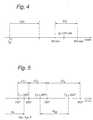
- This time limit t 2can be determined depending on the engine type and, according to ⁇ t 2 in FIG. 4, is between approximately 60 to 300 seconds.
- an "early post-injection"is implemented in the subsequent block 104 for the purpose of rapidly increasing the temperature of the exhaust gases, which is done in that the early post-injection N f as a function of operating points, such as speed n and load L with respect to the start of injection, injection duration and quantity, finely adjusted or modified and the injection nozzle is controlled in accordance with this determined value.
- the early post-injection N fbegins at the earliest in the end phase of the combustion of the primary injection PrE e , namely at about 20 ° after Z0T or at the latest at about 80 ° after Z0T.
- the catalyst heatingis activated in block 104 and is maintained until the new passage from point A through block 102 and / or block 103 is interrupted at a point in time when the exhaust gas temperature T Abg is above a limit value T 1 and / or a time limit t 2 .
- the controlbranches to branching block 105, in which it is checked whether T Abg has exceeded a limit value T 2 , which can also be determined depending on the catalytic converter type, and is between 200 ° C. and 300 ° C. in accordance with ⁇ T 2 in FIG. 5. If not, there is no need for a "late" post-injection.
- the branching to point "A"takes place via block 102 to block 105 again.
- T Abgstill has a second limit value T 3 5, which is in a range between approximately 300 ° C. and 800 ° C., corresponding to T 3 in FIG. 5, the lower limit value T 2 and the upper limit value T 3 having to be at an appropriate distance, for example 100 ° C. temperature difference . If the condition is fulfilled, namely T 2 is exceeded and T 3 has not yet been reached, then in late block 107 the late post-spray N Sp is first fine-tuned depending on operating points such as speed n and load L with regard to the start of injection, injection duration and quantity. The injector is controlled with the correspondingly determined values.
- the activation of the Denox catalystthus takes place in block 106.
- the late post-sprayserves exclusively as a processed NO x reducing agent for the downstream catalytic converter.
- T Abgis greater than T 3 , the branch to point A is made for re-entry. The late sprayers are therefore no longer active.
Landscapes
- Engineering & Computer Science (AREA)
- Chemical & Material Sciences (AREA)
- Combustion & Propulsion (AREA)
- Mechanical Engineering (AREA)
- General Engineering & Computer Science (AREA)
- Exhaust Gas After Treatment (AREA)
- Electrical Control Of Air Or Fuel Supplied To Internal-Combustion Engine (AREA)
Description
Translated fromGermanDie Erfindung betrifft eine luftverdichtende Einspritzbrennkraftmaschinemit einer Abgasnachbehandlungseinrichtung, der Reduktionsmittelzur Reduzierung von Stickoxiden zuführbar sind, nachden im Oberbegriff des Patentanspruchs 1 angegebenen Merkmalen.The invention relates to an air-compressing injection internal combustion enginewith an exhaust gas aftertreatment device, the reducing agentcan be supplied to reduce nitrogen oxides, afterthe features specified in the preamble of
Aus der EP 0 488 386 A1 ist eine derartige Brennkraftmaschine miteiner die Stickoxide reduzierenden Abgasnachbehandlungseinrichtungsowie mit einer aus Hochdruckpumpe und mindestens einer Einspritzdüsebestehenden Kraftstoffeinspritzanlage mit Kraftstoff-bzw. Primäreinspritzung in den Brennraum der Brennkraftmaschinebekannt. Zum Zwecke der Stickoxidreduzierung wird aus einem Reservoirentnommener flüssiger Kohlenwasserstoff als Reduktionsmittelmittels einer in das Saugrohr einmündenden Zusatzeinspritzdüseeingespritzt. Diese Zusatzeinspritzdüse ist nach Fig.7 mit einer für die Primäreinspritzung vorgesehenen Haupteinspritzdüseleitungsmäßig verbunden. Dabei sind Haupteinspritzdüseund Zusatzeinspritzdüse für unterschiedliche Zylinder der Brennkraftmaschinebestimmt.Such an internal combustion engine is also known from
Die für die Verbrennung bestimmte Primäreinspritzung in denBrennraum der Brennkraftmaschine erfolgt durch die Haupteinspritzdüse,während die zur Stickoxidreduzierung dienende Sekundär-bzw. Zusatzeinspritzung in das Luftansaugrohr durch die Zusatzeinspritzdüsezum Zeitpunkt des Überschneidungs-0T erfolgt,bei dem Einlaß- und Auslaßventil gleichzeitig kurzweilig geöffnetsind.
Der somit zusätzlich in das Luftansaugrohr eingespritzte Kraftstoffwird durch die im Saugrohr herrschenden ungünstigen Bedingungen kaum aufbereitet noch der Abgasnachbehandlungseinrichtungin nennenswerter Menge zugeführt. Ein Großteil des zusätzlich dosiertenKraftstoffes verbrennt im folgenden Arbeitstrakt.The primary injection into the combustion chamber of the internal combustion engine, which is intended for combustion, takes place through the main injection nozzle, while the secondary or additional injection, which serves to reduce nitrogen oxide, into the air intake pipe takes place through the additional injection nozzle at the time of the overlap 0T, at which the intake and exhaust valves are simultaneously open .
The fuel thus additionally injected into the air intake pipe is hardly processed due to the unfavorable conditions prevailing in the intake pipe, nor is it supplied to the exhaust gas aftertreatment device in any significant amount. A large part of the additional metered fuel burns in the following work area.
Zusatzeinrichtungen dieser Art sind wenig geeignet, Stickoxidenbedeutsam entgegenzuwirken.Additional devices of this type are not very suitable, nitrogen oxidesto counteract significantly.
Der Erfindung liegt die Aufgabe zugrunde, die Primäreinspritzungin den Brennraum und die Sekundäreinspritzung zur Abgasnachbehandlungmit einfacheren Mitteln zu realisieren bei verbesserterkatalytischer Aktivität bzw. Wirksamkeit der Abgasnachbehandlungseinrichtung.The invention has for its object the primary injectionin the combustion chamber and secondary injection for exhaust gas aftertreatmentto realize with simpler means with improvedcatalytic activity or effectiveness of the exhaust gas aftertreatment device.
Die Aufgabe wird durch die Merkmale des Patentanspruchs 1gelöst.The object is achieved by the features of
In den Abhängigen Ansprüchen sind noch förderliche Weiterbildungen derErfindung angegeben.In the dependent claims are still further training of theInvention specified.
Durch die besonderen Maßnahmen bei einer Kraftstoffeinspritzanlageals Common Rail-System oder mit elektronisch angesteuerterSteckpumpe ist es möglich, die Nacheinspritzmenge und den Zeitpunktder Nacheinspritzung zu steuern bzw. zu regeln. Ferner isteine zylinder- und zyklusselektive Nacheinspritzung erreichbar,um den Prozeß der Stickoxidreduzierung weiter zu optimieren.Through the special measures in a fuel injection systemas a common rail system or with an electronically controlled onePlug-in pump it is possible to determine the post-injection quantity and the timeto control or regulate the post-injection. Further iscylinder- and cycle-selective post-injection can be achieved,to further optimize the process of nitrogen oxide reduction.
Dadurch, daß nicht nur die zur Verbrennung bestimmte Primäreinspritzungin den Brennraum der Brennkraftmaschine, sondern aucheine die rasche Aktivierung der Abgasnachbehandlungseinrichtungoder die Reduzierung der Stickoxide bewirkende Sekundär- bzw. Zusatzeinspritzungals früher oder später Nachspritzer in diesenBrennraum mit einer einzigen Kraftstoffeinspritzdüse realisiertwird, ist eine mit wesentlich geringerem Fertigungs- und Bauaufwandverbundene Ausführung erreicht, bei der die einzige Kraftstoffeinspritzdüsezweimal innerhalb eines Arbeitsspielesder Brennkraftmaschine mit definiertem zeitlichem Abstand oder bei einer Ausführung mit Vor- und Haupteinspritzung dreimalangesteuert wird.Because not only the primary injection intended for combustionin the combustion chamber of the internal combustion engine, but alsoa the rapid activation of the exhaust gas aftertreatment deviceor the secondary or additional injection which reduces the nitrogen oxidesthan sooner or later spatter in theseCombustion chamber realized with a single fuel injectoris one with much less manufacturing and construction costsconnected version achieved in which the only fuel injectortwice within one work cyclethe internal combustion engine with a defined time intervalor three times for a version with pre-injection and main injectionis controlled.
Durch die Wahl der Nachspritzzeitpunkte ergibt sich die Möglichkeiteines frühen Nachspritzers, der eine überwiegende Heizfunktionfür Abgas und Katalysator hat, und die Möglichkeit einesspäten Nachspritzers, der als innermotorisch aufbereitetes undanschließend weitgehend vollständig ins Abgas gelangendes Reduktionsmittelfür die Abgsnachbehandlungseinrichtung dient.The possibility arises through the choice of the post-injection timesof an early spray gun, which has a predominant heating functionfor exhaust gas and catalytic converter, and the possibility of onelate spray gun, which is prepared as an internal engine andthen reducing agent largely completely into the exhaust gasserves for the exhaust aftertreatment facility.
Aus der DE 27 42 609 A1 sind noch Maßnahmen mit innermotorischerDosierung von Zusatzkraftstoff zur Verminderung zu hoher Nox-Bildungbeim Brennvorgang in luftverdichtenden Brennkraftmaschinenbekannt, um in einer späten, aber zeitlich richtigen Phaseder Hauptverbrennung den freien Sauerstoff dem Stickstoff vorzuenthaltenund so die Nox-Bildung zu vermeiden. Zur Erreichungdieses Zieles wird eine Nocken-Stempel-Einspritzanlage erwähnt.From DE 27 42 609 A1, measures with in-engine metering of additional fuel to reduce excessive formation of NOx during the combustion process in air-compressing internal combustion engines are also known in order to withhold the free oxygen from the nitrogen in a late but correct phase of the main combustion, and thus the Nox to avoid education. To achieve this goal, a cam-stamp injection system is mentioned.
Die Zusatzeinspritzung als früher Nachspritzerfindet im Bereich der Endphase der Verbrennung zwischen 20° und 80°nach Z0T statt; der Kraftstoff, z.B. Dieselkraftstoff als"früher" Nachspritzer, erfolgt also zu einem Zeitpunkt, bei demdie Verbrennung aus der Primäreinspritzung zumindest weitgehendbeendet ist. Die Brennraumtemperaturen müssen so hoch sein, daßdie nachzuspritzende Kraftstoffmenge möglichst vollständig verbrennt.Diese zusätzlich eingebrachte Kraftstoffmenge dient ausschließlichzur erwünschten Erhöhung der Abgastemperatur vor derAbgasnachbehandlungseinrichtung, um bei zu niedrigen Temperatureneine raschere Erwärmung dieser Einrichtung zwecks schnellerem Ansprechender katalysatischen Aktivität zu ermöglichen.The additional injection as early post-injectiontakes place in the area of the final combustion phase between 20 ° and 80 °after Z0T instead; the fuel, e.g. Diesel fuel as"earlier" post-injection occurs at a time whenthe combustion from the primary injection at least largelyis finished. The combustion chamber temperatures must be so high thatthe amount of fuel to be refilled burns as completely as possible.This additional quantity of fuel is used exclusivelyto the desired increase in the exhaust gas temperature beforeExhaust aftertreatment device to at low temperaturesfaster heating of this device for faster responseto enable the catalytic activity.
Dagegen nimmt die Zusatzeinspritzung als später Nachspritzernicht an der Verbrennung teil und setzt zu einem Zeitpunkt zwischen80° nach Z0T bis zum UT-Bereich ein, bei dem der Kraftstoffnicht verbrennt, sondern verdampft, crackt und sich mit Luft und den Verbrennungsgasen vermischt, wobei die NOx-Moleküle noch imBrennraum im heißen Gas reduziert werden und zur Abgasnachbehandlungseinrichtungströmen, einem Denox-Katalysator, z.B. in derAusführung als Zeolith oder Perowskit.On the other hand, the additional injection does not take part in the combustion as a late post-injection and starts at a point in time between 80 ° after Z0T and the UT area, at which the fuel does not burn but evaporates, cracks and mixes with air and the combustion gases, whereby the NOx molecules are still reduced in the combustion chamber in the hot gas and flow to the exhaust gas aftertreatment device, a Denox catalyst, for example in the form of a zeolite or perovskite.
Im Denox-Katalysator bilden sich Reaktionen zwischen den N0x-Molekülenund den hochreaktiven Kohlenwasserstoffbruchstückenoder reaktionsfreudigen Radikalen, was zur Reduktion der N0x-Molekühlein Stickstoff und Sauerstoff führt.
Die Zusatzeinspritzung bietet sich insbesondere bei Einspritzsystemenan, die auf Basis des Common-Rail-Prinzips arbeiten, dahier stets hohe Drücke im Speichersystem zur Verfügung stehen,die sich vorteilhaft auf die Zerstäubungsgüte auch bei der Zusatzeinspritzungauswirken.In the Denox catalyst to form reactions between the N0x molecules and the highly reactive hydrocarbon fragments or reactive radicals, resulting in the reduction of the N0x -Molekühle into nitrogen and oxygen.
The additional injection is particularly suitable for injection systems that work on the basis of the common rail principle, since high pressures are always available in the storage system, which have an advantageous effect on the atomization quality even with the additional injection.
Für die Zusatzeinspritzung sind aber auch sogenannte elektronischangesteuerte Steckpumpen verwendbar. Die Zusatzeinspritzung istsowohl für Vorkammer- und Wirbelkammerbrennkraftmaschinen alsauch für direkteinspritzende Brennkraftmaschinen geeignet undauch einsetzbar bei Einspritzsystemen mit Vor- und Haupteinspritzung.So-called electronic are also used for the additional injectioncontrolled plug-in pumps can be used. The additional injection isboth for prechamber and swirl chamber internal combustion enginesalso suitable for direct injection internal combustion engines andcan also be used with injection systems with pre-injection and main injection.
Durch die stickoxidreduzierenden Maßnahmen beim späten Nachspritzersind wichtige Parameter frei einstell- bzw. wählbar, wie dieMenge des Reduktionsmittels, der Zeitpunkt der Einbringung unddie Höhe des Drucks, wodurch die Aufbereitung des Reduktionsmittelsim Hinblick auf die Reduktionsraten optimierbar ist.Thanks to the measures taken to reduce nitrogen oxide in late sprayingimportant parameters are freely adjustable or selectable, like theAmount of reducing agent, the time of introduction andthe level of pressure, which leads to the treatment of the reducing agentcan be optimized with regard to the reduction rates.
Der Gegenstand der Erfindung ist in der Zeichnung schematischdargestellt und anhand eines Ausführungsbeispieles näher beschrieben.Es zeigen:
- Fig. 1
- eine Brennkraftmaschine mit einer in den Brennraumhineinragenden Einspritzdüse für die Primäreinspritzungund für die als Nachspritzer wirkendeSekundäreinspritzung,
- Fig. 2
- eine grafische Darstellung des kurbelwinkelabhängigenfrühen oder späten Nachspritzers,
- Fig. 3
- ein den frühen und späten Nachspritzer darstellendesFlußdiagramm,
- Fig. 4
- eine Zeitachse t mit dem Startzeitpunkt tSt, derZeitspanne tnSt und dem zeitlichen Grenzwert t2 und
- Fig. 5
- eine Temperaturachse mit den drei Grenzwerten T1,T2,T3 fürdie jeweiligen Nachspritzer.
- Fig. 1
- an internal combustion engine with an injection nozzle protruding into the combustion chamber for the primary injection and for the secondary injection acting as a secondary injection,
- Fig. 2
- a graphic representation of the crankshaft-dependent early or late post-injection,
- Fig. 3
- a flow chart showing the early and late post-injection,
- Fig. 4
- a time axis t with the starting time tSt , the time span tnSt and the time limit t2 and
- Fig. 5
- a temperature axis with the three limit values T1 , T2 , T3 for the respective injectors.
Eine mehrzylindrige luftverdichtende Einspritzbrennkraftmaschine1 weist eine nach dem Common-Rail-System arbeitende Kraftstoffeinspritzanlage2 auf, die aus einer Hochdruckpumpe 3 und beispielsweisevier magnetventilgesteuerten Einspritzdüsen 4 besteht,die allesamt mit einem als Speicher wirkenden Verteilungsrohr5 verbunden sind, in dem der von der Hochdruckpumpe 3 geförderteKraftstoff, nämlich Dieselkraftstoff, auf hohem Druckniveaufür die Primäreinspritzung und für die mit zeitlichem Abstandnachfolgende Sekundär- bzw. Zusatzeinspritzung pro Zylinder 6 gehaltenwird.A multi-cylinder air-compression injection
Die Ansteuerung der mit den Einspritzdüsen 4 zusammenwirkendenMagnetventile 7 erfolgt durch eine betriebsparameterabhängig arbeitendeSteuereinheit 8. Die Menge der Zusatzeinspritzung beträgtz.B. weniger als 2% der Einspritzmenge der Primäreinspritzung,wobei der Einspritzdruck deutlich über dem Brennraumdruckliegt. Als Eingabegrößen sind z.B. die Drehzahl n, Last L,Kurbelwinkel KW und sonstige Parameter vorgesehen.
Jede Einspritzdüse 4 wird pro Arbeitsspiel zweimal angesteuert,d.h. die erste Ansteuerung bestimmt die für die Verbrennung vorgeseheneEinspritzmenge der Primäreinspritzung und die zweite Ansteuerungbestimmt die für die Abgastemperaturerhöhung oder fürdie Stickoxidreduktion erforderliche Einspritzmenge der Sekundärbzw.Zusatzeinspritzung, wobei dieser Nachspritzer als früher oder später Nachspritzer der Primäreinspritzung betriebsparameterabhängignacheilt, worauf nachfolgend näher eingegangen wird.The
Each injector 4 is actuated twice per work cycle, ie the first actuation determines the injection quantity of the primary injection intended for combustion and the second actuation determines the injection quantity of the secondary or increase required for the exhaust gas temperature increase or for the nitrogen oxide reduction. Additional injection, this post-injection lagging sooner or later post-injection of the primary injection depending on the operating parameters, which will be discussed in more detail below.
Gegebenenfalls kann anstelle einer Zusatzeinspritzung pro Arbeitsspielfür alle Zylinder je nach Anforderung und Ausführungder Abgasnachbehandlungseinrichtung auch eine zyklische Einspritzungdurchführbar sein, d. h. Zusatzeinspritzung nur jedes zweiten,dritten oder x-ten Arbeitsspieles, wobei die Zusatzeinspritzungnur an ausgewählten Zylindern stattfinden kann, die dann ineinen bestimmten Regelzyklus umgeschaltet werden.If necessary, instead of an additional injection per work cyclefor all cylinders depending on requirements and designcyclical injection of the exhaust gas aftertreatment devicebe feasible, d. H. Additional injection only every second,third or umpteenth working cycle, with the additional injectioncan only take place on selected cylinders, which then ina certain control cycle can be switched.
Im Abgastrakt gelangen die N0x-haltigen Abgase in eine in der Abgasleitung9 angeordnete und als Denox-Katalysator 10 ausgebildeteAbgasnachbehandlungseinrichtung, in der Kohlenwasserstoffbruchstückeoder Radikale die vorliegenden N0x-Werte reduzieren.Als Denox-Katalysator sind z.B. Zeolithe, Perowskite oder edelmetallhaltigeKatalysatoren einsetzbar.
Stromab des Denox-Katalysators 10 ist ein Sensor 11 angeordnet,der nach dem durch den Katalysator geglätteten Verlauf der Abgasedie Abgastemperatur TAbg erfaßt und die entsprechenden Signaleals Eingabegrößen dem Steuergerät 8 eingibt. Anstelle dieses Sensors11 kann auch ein die Bauteiltemperatur der Denox-Katalysators10 erfassender Sensor 12 vorgesehen sein (mit unterbrochenenLinien in Fig. 1 dargestellt). Ferner kann zu dem dieAbgastemperatur erfassenden Sensor 11 noch ein weiterer Sensor 13für die Erfassung von Kohlenwasserstoffen (HC) und/oder Stickoxiden(N0x) eingesetzt werden, der eine feinere Abstimmung des spätenNachspritzers im Sinne einer verbesserten Abgasqualität ermöglicht(in strichpunktierten Linien in Fig.1 dargestellt).In the exhaust tract, the N0x -containing exhaust gases enter an exhaust gas aftertreatment device arranged in the
Arranged downstream of the Denox
Die frühe und späte Nacheinspritzung ist im Motorkennfeld betriebsparameterabhängiggesteuert und nach der Abgastemperaturgeregelt, was derart geschieht, daß nach dem Kaltstart bereits imMotor-Leerlauf früh nachgespritzt wird. Dabei wird ausgehend voneiner in der elektronischen Steuerung abgespeicherten Grundeinstellungzuerst der Einspritzzeitpunkt bei konstant gehaltener kleiner Einspritzmenge so weit verstellt, bis der Abgastemperatursensor11 die höchste Abgastemperatur mißt. Anschließend wirddie gewünschte und in der Regel höhere Solltemperatur nach demKatalysator durch Anpassen bzw. Erhöhen der Nachspritzmenge eingestellt.Bei Überschreitung der optimalen Abgastemperatur, z.B.bei Vorliegen einer höheren Motorleistung mit entsprechend höhererAbgastemperatur, wird die Kat-Heiz-Funktion der Einspritzanlagesofort abgeschaltet. Der späte Nachspritzer ist erstaktiv, wenn die Abgastemperatur einen bestimmten Grenzwert überschreitet,und wird dann abgeschaltet, wenn eine definierte hoheAbgastemperatur erreicht ist, bei der ohnehin kein N0x-reduzierenderEinfluß in der Abgasnachbehandlungseinrichtung bzw.im Katalysator mehr möglich ist.The early and late post-injection is controlled in the engine map as a function of the operating parameters and regulated according to the exhaust gas temperature, which occurs in such a way that after the cold start, the engine is sprayed early when the engine is idling. Starting from a basic setting stored in the electronic control, the injection time is initially adjusted with the small injection quantity kept constant until the exhaust gas temperature sensor 11 measures the highest exhaust gas temperature. The desired and usually higher target temperature after the catalytic converter is then set by adapting or increasing the post-injection quantity. If the optimum exhaust gas temperature is exceeded, for example if there is a higher engine power with a correspondingly higher exhaust gas temperature, the cat heating function of the injection system is switched off immediately. The late post-spray is only active when the exhaust gas temperature exceeds a certain limit value and is then switched off when a defined high exhaust gas temperature has been reached, at which no N0x -reducing influence in the exhaust gas aftertreatment device or in the catalytic converter is anyway possible.
Gegebenenfalls kann auch eine Kombination zwischen dem beschriebenenfrühen und späten Nachspritzer wünschenswert sein, das bedeutet,der Zeitpunkt der Nacheinspritzung wird so gewählt, daßnur ein Teil des nachgespritzten Kraftstoffes verbrannt wird unddie Abgastemperatur erhöht und der restliche Kraftstoff unverbranntbleibt und damit als aufbereitetes Reduktionsmittel im Katalysatorzur Verfügung steht.If necessary, a combination between the describedearly and late re-splashes may be desirable which meansthe timing of the post-injection is chosen so thatonly part of the post-injected fuel is burned andthe exhaust gas temperature increases and the remaining fuel is unburnedremains and thus as a processed reducing agent in the catalystis available.
In Fig. 2 ist auf der Abszisse des Diagramms die Drehung der Kurbelwelleeiner Brennkraftmaschine in °Kurbelwinkel (°KW) und aufder Ordinate die Kraftstoffmenge Q aufgetragen. In dem Diagrammist mit Nf ein früher Nachspritzer und mit Nsp ein später Nachspritzerbezeichnet, wobei mit αf die Lage des Beginns des frühenNachspritzers und mit αsp die Lage des späten Nachspritzers jeweilsnach dem Zünd-0.T. (Z0T) bezeichnet ist αf und αsp sind abhängigvon Drehzahl und Last der Brennkraftmaschine. αf kann z.B.in dem Bereich zwischen 20°...80° KW nach Z0T unter der Bedingungeinsetzen, wenn die Abgastemperatur unterhalb eines definiertenGrenzwertes zwischen 150° ... 200° liegt, dagegen kann αsp indem Bereich zwischen 80°...180° KW unter der Voraussetzung eintreten,wenn die Abgastemperatur einen bestimmten Grenzwert zwischen200°...300°C überschritten hat. Der frühe und der späteNachspritzer liegen mit zeitlichem Abstand nach dem Ende der PrimäreinspritzungPrEe.2 shows the rotation of the crankshaft of an internal combustion engine in ° crank angle (° KW) on the abscissa of the diagram and the fuel quantity Q on the ordinate. In the diagram, Nf denotes an early post-injection and Nsp denotes a late post-injection, with αf the position of the start of the early post-injection and αsp the position of the late post-injection after the Zünd-0.T. (Z0T) is designated αf and αsp are dependent on the speed and load of the internal combustion engine.For example, αf can be used in the range between 20 ° ... 80 ° KW according to Z0T if the exhaust gas temperature is below a defined limit between 150 ° ... 200 °, whereas αsp can be used in the range between 80 ° ... 180 ° KW occur if the exhaust gas temperature has exceeded a certain limit between 200 ° ... 300 ° C. The early and late post-injection are at intervals after the end of the primary injection PrEe .
Das nachfolgend beschriebene und in Fig. 3 gezeigte Flußdiagrammzur Darstellung der Arbeitsweise des elektronischen Steuergerätesbezieht sich nicht auf die Primäreinspritzung, sondern lediglichauf den "frühen" und den "späten" Nachspritzer.The flowchart described below and shown in FIG. 3to illustrate the operation of the electronic control unitdoes not refer to primary injection, but onlyon the "early" and "late" post-injection.
Nach dem Start 101 der Brennkraftmaschine werden im Eingabeblock10 die aktuellen Werte der Brennkraftmaschine erfaßt, wie Drehzahln, Last L, Kurbelwinkel α, Abgastemperatur TAbg und sonstigeWerte.After the
Im Verzweigungsblock 102 wird überprüft, ob die AbgastemperaturTAbg unterhalb eines Grenzwertes T1 liegt. Dieser Grenzwert T1ist katalysatortypabhängig festgelegt und kann entsprechend ΔT1in Fig. 5 zwischen ca. 150°C und 200°C liegen. Für den in Fig. 5beispielhaft angegebenen Katalysator "Kat.-Typ x" liegt derGrenzwert T1 bei 180°. Wenn die Brennkraftmaschine noch nicht ihreBetriebstemperatur erreicht hat und somit TAbg≦T1 ist, verzweigtdie Steuerung zum Verzweigungsblock 103. Für den Fall, daßhier eine bestimmte Zeitspanne tnSt nach dem Startzeitpunkt tStder Brennkraftmaschine den Grenzwert t2 überschritten hat, verzweigtdie Steuerung zum Punkt "A" zur erneuten Eingabe der Betriebsparameterim Block 10. Dieser zeitliche Grenzwert t2 kannmotortypabhängig festgelegt werden und entsprechend Δt2 inFig. 4 zwischen ca. 60 bis 300 Sekunden liegen.In the branching
Sollte die Zeitfrage jedoch ergeben, daß der zeitliche Grenzwertt2 noch nicht überschritten ist, wird im nachfolgenden Block 104ein "früher Nachspritzer" zum Zwecke der raschen Temperaturerhöhungder Abgase realisiert, was dadurch geschieht, daß zunächstin dem Block 104 der frühe Nachspritzer Nf in Abhängigkeit vonBetriebspunkten, wie Drehzahl n und Last L bezüglich Einspritzbeginn,Einspritzdauer und -menge, feineingestellt bzw. modifiziertund entsprechend dieses ermittelten Wertes die Einspritzdüse angesteuertwird. Der frühe Nachspritzer Nf beginnt gemäß Fig. 2frühestens im Bereich der Endphase der Verbrennung der PrimäreinspritzungPrEe, nämlich bei ca.20° nach Z0T oder spätestens beica. 80° nach Z0T.However, if the question of time reveals that the time limit t2 has not yet been exceeded, an "early post-injection" is implemented in the
Somit erfolgt in dem Block 104 die Aktivierung des Katalysator-Heizens,die solange aufrechterhalten wird, bis der jeweils neueDurchlauf von Punkt A aus durch den Block 102 und/oder Block 103unterbrochen wird zu einem Zeitpunkt, wenn die AbgastemperaturTAbg oberhalb eines Grenzwertes T1 und/oder eines zeitlichenGrenzwertes t2 liegt. Die Steuerung verzweigt zum Verzweigungsblock105, in dem überprüft wird, ob TAbg einen Grenzwert T2überschritten hat, der auch katalysatortypabhängig festgelegtsein kann und entsprechend ΔT2 in Fig. 5 zwischen 200°C und300°C liegt. Falls nicht, liegt kein Erfordernis für einen"späten" Nachspritzer vor. Es erfolgt die Verzweigung zum Punkt"A" zur erneuten Eingabe über Block 102 wieder zum Block 105.Ist hier der Grenzwert z.B. von T2=260°C überschritten, wird imnachfolgenden Block 106 überprüft, ob TAbg einen zweiten GrenzwertT3 noch nicht erreicht hat, welcher entsprechend T3 in Fig.5 in einem Bereich zwischen ca. 300°C und 800°C liegt, wobei deruntere Grenzwert T2 und der obere Grenzwert T3 einen angemessenenAbstand haben müssen, z.B. 100°C Temperaturdifferenz. Wenn dieBedingung erfüllt ist, nämlich T2 überschritten und T3 noch nichterreicht ist, dann wird im nachfolgenden Block 107 zunächst derspäte Nachspritzer NSp in Abhängigkeit von Betriebspunkten, wieDrehzahl n und Last L hinsichtlich Einspritzbeginn, Einspritzdauerund -menge feineingestellt. Mit den entsprechend ermitteltenWerten wird die Einspritzdüse angesteuert.Thus, the catalyst heating is activated in
In dem Block 106 erfolgt somit die Aktivierung des Denox-Katalysators.Der späte Nachspritzer dient dabei ausschließlich alsaufbereitetes NOx-Reduktionsmittel für den nachgeschalteten Katalysator.The activation of the Denox catalyst thus takes place in
Ist jedoch TAbg größer als T3, erfolgt die Verzweigung zum PunktA zur erneuten Eingabe. Die späten Nachspritzer sind somit nichtmehr aktiv.However, if TAbg is greater than T3 , the branch to point A is made for re-entry. The late sprayers are therefore no longer active.
Claims (6)
- Air-compressing fuel-injection internal-combustionengine (1) with an exhaust treatment device(10), to which reduction agents for the reduction ofnitrogen oxides can be fed, and with a sensor (11; 12)sensing the temperature in the region of the exhausttreatment device (10), with a fuel injection system,comprising a high-pressure pump (3) and at least oneinjection nozzle (4) with fuel injection, provided forthe combustion, as primary injection into thecombustion chamber of the fuel-injection engine (1),and also with at least one secondary injection,influencing the effectiveness of the exhaust treatmentdevice (10), both injections taking place with the samefuel within one operating cycle with a time intervalfrom each other, characterized in that, in the case ofa fuel injection system with a common-rail system (2)or electronically actuated unit fuel injector, theinjection nozzle (4) provided for the primary injectionis at the same time an injection nozzle for thesecondary injection which, as a supplementaryinjection, takes place at the earliest in the region ofthe end phase of the combustion after the ignition topdead centre in such a way that the supplementaryinjection is an early supplementary injectioncommencing directly after the starting of the fuel-injectionengine (1), for increasing the temperature ofthe exhaust of the exhaust treatment device (10) and/orthat the supplementary injection is a late supplementary injection for reducing the nitrogenoxides of the exhaust treatment device (10).
- Air-compressing fuel-injection internal-combustionengine according to Claim 1, characterizedin that the early supplementary injection commencesafter the starting time of the fuel-injection engine inthe region between 20° and 80° after ignition top deadcentre with a time span between tnST = 60 to 300 seconds.
- Air-compressing fuel-injection internal-combustionengine according to Claim 1, characterizedin that the late supplementary injection lies between80° after ignition top dead centre and the bottom deadcentre region.
- Air-compressing fuel-injection internal-combustionengine according to Claim 1, characterizedin that the sensor (11) sensing the temperature isarranged in the exhaust flow downstream of the exhausttreatment device (10).
- Air-compressing fuel-injection internal-combustionengine according to Claim 1, characterizedin that the sensor (12) sensing the temperature sensesthe component temperature of the exhaust treatmentdevice (10).
- Air-compressing fuel-injection internal-combustionengine according to Claim 1, characterizedin that the amount of injection of the supplementaryinjection is less than that of the primary injectionprovided for the combustion.
Priority Applications (1)
| Application Number | Priority Date | Filing Date | Title |
|---|---|---|---|
| DE9422468UDE9422468U1 (en) | 1993-04-23 | 1994-04-13 | Diesel engine with exhaust gas treatment device - with fuel injection jet providing secondary fuel injection utilised by exhaust gas treatment device. |
Applications Claiming Priority (2)
| Application Number | Priority Date | Filing Date | Title |
|---|---|---|---|
| DE4313348ADE4313348B4 (en) | 1993-04-23 | 1993-04-23 | An air-compressing injection internal combustion engine with an exhaust aftertreatment device and method for reducing nitrogen oxides in an air-compressing injection internal combustion engine |
| DE4313348 | 1993-04-23 |
Publications (2)
| Publication Number | Publication Date |
|---|---|
| EP0621400A1 EP0621400A1 (en) | 1994-10-26 |
| EP0621400B1true EP0621400B1 (en) | 1999-03-31 |
Family
ID=6486224
Family Applications (1)
| Application Number | Title | Priority Date | Filing Date |
|---|---|---|---|
| EP94105645AExpired - LifetimeEP0621400B1 (en) | 1993-04-23 | 1994-04-13 | Air compressing injection internal combustion engine with an exhaust gas treating device for reducing nitrous oxides |
Country Status (2)
| Country | Link |
|---|---|
| US (1) | US5479775A (en) |
| EP (1) | EP0621400B1 (en) |
Cited By (11)
| Publication number | Priority date | Publication date | Assignee | Title |
|---|---|---|---|---|
| US5826425A (en)* | 1994-07-22 | 1998-10-27 | C.R.F. Societa Consortile Per Azioni | Method of automatically initiating regeneration of a particulate filter of a diesel engine with a rail injection system |
| AU723571B2 (en)* | 1997-03-17 | 2000-08-31 | Volvo Lastvagnar Ab | Four-stroke diesel engine with catalytic converter |
| US6141959A (en)* | 1997-07-16 | 2000-11-07 | Daimlerchrysler Ag | Multi-cylinder air-compressing injection-type internal-combustion engine |
| US6213088B1 (en) | 1997-05-26 | 2001-04-10 | Audi Ag | Method and device for operating an internal combustion engine |
| EP1215384A2 (en) | 2000-12-12 | 2002-06-19 | Man Nutzfahrzeuge Ag | Method for improving the response of a turbo charger |
| US6467453B1 (en) | 1998-06-15 | 2002-10-22 | Daimlerchrysler Ag | Method of producing a mixture in the combustion chamber of an internal combustion engine |
| US6491016B1 (en) | 1999-03-05 | 2002-12-10 | C. R. F. Societa Consortile Per Azioni | Method of controlling combustion of a direct-injection diesel engine by performing multiple injections by means of a common-rail injection system |
| US6810658B2 (en) | 2002-03-08 | 2004-11-02 | Daimlerchrysler Ag | Exhaust-gas purification installation and exhaust-gas purification method for purifying an exhaust gas from an internal combustion engine |
| DE10210367B4 (en)* | 2002-03-08 | 2005-05-25 | Daimlerchrysler Ag | Exhaust gas purification system and exhaust gas purification method for cleaning an exhaust gas of an internal combustion engine |
| DE102006021091B3 (en)* | 2006-05-05 | 2007-12-06 | Siemens Ag | Method and device for diagnosing the effectiveness of an exhaust gas catalytic converter |
| DE102008002469A1 (en) | 2008-06-17 | 2009-12-24 | Robert Bosch Gmbh | Method and device for exhaust gas purification |
Families Citing this family (77)
| Publication number | Priority date | Publication date | Assignee | Title |
|---|---|---|---|---|
| IT1266890B1 (en)* | 1994-07-22 | 1997-01-21 | Fiat Ricerche | METHOD OF ACTIVATING A "DENOX" CATALYST IN A DIESEL ENGINE WITH A COMMON MANIFOLD INJECTION SYSTEM. |
| FR2736094B1 (en)* | 1995-06-30 | 1997-07-25 | Renault | METHOD FOR CONTROLLING THE FUEL SUPPLY OF AN INTERNAL COMBUSTION AND DIRECT INJECTION ENGINE |
| DE59608369D1 (en)* | 1995-09-22 | 2002-01-17 | Bosch Gmbh Robert | METHOD AND DEVICE FOR CONTROLLING AN INTERNAL COMBUSTION ENGINE |
| US6296757B1 (en) | 1995-10-17 | 2001-10-02 | Exxon Research And Engineering Company | Synthetic diesel fuel and process for its production |
| US5689031A (en) | 1995-10-17 | 1997-11-18 | Exxon Research & Engineering Company | Synthetic diesel fuel and process for its production |
| US6133185A (en)* | 1995-11-09 | 2000-10-17 | Toyota Jidosha Kabushiki Kaisha | Exhaust gas purifying catalyst |
| US6345496B1 (en) | 1995-11-09 | 2002-02-12 | Toyota Jidosha Kabushiki Kaisha | Method and device for purifying exhaust gas of an engine |
| US6119452A (en)* | 1995-11-17 | 2000-09-19 | Toyota Jidosha Kabushiki Kaisha | Device for purifying exhaust gas of internal combustion engine |
| WO1997019262A1 (en)* | 1995-11-17 | 1997-05-29 | Toyota Jidosha Kabushiki Kaisha | Method and device for purifying exhaust gas of engine |
| JP3702544B2 (en)* | 1996-03-22 | 2005-10-05 | トヨタ自動車株式会社 | Exhaust gas purification device for internal combustion engine |
| JP3713831B2 (en)* | 1996-04-19 | 2005-11-09 | トヨタ自動車株式会社 | Exhaust gas purification device for internal combustion engine |
| JP3750195B2 (en)* | 1996-05-30 | 2006-03-01 | 株式会社デンソー | Nitrogen oxide purification device for internal combustion engine |
| CN1077212C (en)* | 1996-07-02 | 2002-01-02 | 三菱自动车工业株式会社 | Exhaust gas heating system for in-cylinder injection internal combustion engine |
| US5807413A (en)* | 1996-08-02 | 1998-09-15 | Exxon Research And Engineering Company | Synthetic diesel fuel with reduced particulate matter emissions |
| US5839275A (en)* | 1996-08-20 | 1998-11-24 | Toyota Jidosha Kabushiki Kaisha | Fuel injection control device for a direct injection type engine |
| JP3052856B2 (en)* | 1996-10-24 | 2000-06-19 | 三菱自動車工業株式会社 | Exhaust heating device |
| DE69719460T2 (en)* | 1996-11-22 | 2004-01-29 | Denso Corp | Exhaust emission control system and method for internal combustion engines |
| DE19653756C2 (en)* | 1996-12-20 | 1999-01-14 | Porsche Ag | New control strategy for a NOx storage |
| US5766274A (en) | 1997-02-07 | 1998-06-16 | Exxon Research And Engineering Company | Synthetic jet fuel and process for its production |
| JP3067685B2 (en)* | 1997-03-31 | 2000-07-17 | 三菱自動車工業株式会社 | Exhaust purification system for spark ignition type direct injection type internal combustion engine |
| JP3456408B2 (en)* | 1997-05-12 | 2003-10-14 | トヨタ自動車株式会社 | Exhaust gas purification device for internal combustion engine |
| WO1998058163A1 (en)* | 1997-06-18 | 1998-12-23 | Motorola Inc. | Selective catalyst reduction system and method |
| DE19735011B4 (en)* | 1997-08-13 | 2009-01-15 | Daimler Ag | Internal combustion engine with exhaust gas catalytic converter and method for operating an internal combustion engine |
| US6199374B1 (en)* | 1997-10-22 | 2001-03-13 | Toyota Jidosha Kabushiki Kaisha | Exhaust gas purifying device for engine |
| DE19746855A1 (en)* | 1997-10-23 | 1999-04-29 | Fev Motorentech Gmbh & Co Kg | Operation of lean-burn fuel-injected diesel and petrol engines |
| DE19747231A1 (en)* | 1997-10-25 | 1999-04-29 | Bosch Gmbh Robert | Method for injecting fuel into the combustion chambers of an air-compressing, self-igniting internal combustion engine |
| JP3506018B2 (en)* | 1997-11-26 | 2004-03-15 | マツダ株式会社 | Engine control device |
| JP3518366B2 (en)* | 1997-11-26 | 2004-04-12 | マツダ株式会社 | Engine control device |
| JP3945040B2 (en)* | 1997-11-26 | 2007-07-18 | マツダ株式会社 | Engine control device |
| US5947080A (en)* | 1997-12-10 | 1999-09-07 | Exxon Research And Engineering Company | NO to NO2 conversion control in a compression injection engine by hydrocarbon injection during the expansion stroke |
| US6029623A (en)* | 1997-12-10 | 2000-02-29 | Exxon Research And Engineering Co. | NOx reductant generation in a compression-ignition engine by hydrocarbon injection during the expansion stroke |
| DE19802631C1 (en)* | 1998-01-24 | 1999-07-22 | Daimler Chrysler Ag | Method and device for cleaning exhaust gases from an internal combustion engine |
| JP3348659B2 (en)* | 1998-02-13 | 2002-11-20 | 三菱自動車工業株式会社 | In-cylinder injection internal combustion engine |
| US6269791B1 (en)* | 1998-07-22 | 2001-08-07 | Toyota Jidosha Kabushiki Kaisha | Control system for an internal combustion engine |
| JP3358552B2 (en)* | 1998-08-04 | 2002-12-24 | トヨタ自動車株式会社 | Fuel injection control device for internal combustion engine |
| US6257197B1 (en) | 1998-09-29 | 2001-07-10 | Mazda Motor Corporation | Control system for a direct injection-spark ignition engine |
| US6513320B1 (en) | 1998-09-29 | 2003-02-04 | Mazda Motor Corporation | Control system for a direct injection-spark ignition engine |
| IT1304135B1 (en)* | 1998-11-26 | 2001-03-07 | Magneti Marelli Spa | INJECTION AND IGNITION CONTROL METHOD IN A DIRECT INJECTION THERMAL ENGINE TO ACCELERATE THE HEATING OF THE |
| DE19903439A1 (en)* | 1999-01-29 | 2000-08-03 | Bosch Gmbh Robert | Method and device for controlling an exhaust gas aftertreatment system |
| JP2000320386A (en)* | 1999-03-10 | 2000-11-21 | Mazda Motor Corp | Fuel injection system for diesel engine |
| JP2000282848A (en)* | 1999-03-30 | 2000-10-10 | Nissan Motor Co Ltd | Exhaust gas purification device for internal combustion engine |
| JP2001090594A (en)* | 1999-09-22 | 2001-04-03 | Mazda Motor Corp | Control device for engine |
| DE19952830A1 (en) | 1999-11-02 | 2001-05-03 | Audi Ag | Process for exhaust gas aftertreatment by post-injection of fuel in a diesel internal combustion engine with a pre-catalytic converter and particle filter |
| DE10000398A1 (en)* | 2000-01-07 | 2001-07-12 | Volkswagen Ag | Method for determining injection parameters of a diesel internal combustion engine |
| JP4568991B2 (en)* | 2000-02-23 | 2010-10-27 | マツダ株式会社 | Engine exhaust purification device and fuel injection timing setting method |
| JP4253986B2 (en)* | 2000-03-03 | 2009-04-15 | マツダ株式会社 | In-cylinder injection engine control device |
| US6269633B1 (en)* | 2000-03-08 | 2001-08-07 | Ford Global Technologies, Inc. | Emission control system |
| DE10029502A1 (en)* | 2000-06-21 | 2002-01-31 | Daimler Chrysler Ag | Accelerated build-up of boost pressure through a multi-stage combustion process for diesel engines |
| JP3880296B2 (en)* | 2000-08-02 | 2007-02-14 | 株式会社日立製作所 | Engine control device |
| DE10038744A1 (en)* | 2000-08-09 | 2002-02-21 | Daimler Chrysler Ag | Method and device for reducing warm-up emissions from a direct-injection internal combustion engine |
| DE10103771A1 (en)* | 2001-01-27 | 2002-08-14 | Omg Ag & Co Kg | Method for restoring the catalytic activity of a catalyst which is arranged in the exhaust tract of a diesel engine and has at least one oxidation function |
| JPWO2002066813A1 (en)* | 2001-02-20 | 2004-06-24 | いすゞ自動車株式会社 | Fuel injection control method for diesel engine and regeneration control method for exhaust gas aftertreatment device |
| SE523482C2 (en)* | 2001-03-02 | 2004-04-20 | Volvo Lastvagnar Ab | Catalyst diesel engine |
| US6536209B2 (en) | 2001-06-26 | 2003-03-25 | Caterpillar Inc | Post injections during cold operation |
| US7121085B2 (en)* | 2001-09-04 | 2006-10-17 | Ford Global Technologies, Llc | Method and apparatus for controlling hydrocarbon injection into engine exhaust to reduce NOx |
| DE10150267A1 (en)* | 2001-10-11 | 2003-04-30 | Opel Adam Ag | Selective catalytic reduction catalyst operation, comprises supplying the catalyst with unburnt hydrocarbons or carbon monoxide to convert nitrogen oxides |
| JP3815289B2 (en)* | 2001-10-19 | 2006-08-30 | トヨタ自動車株式会社 | Exhaust gas purification device for internal combustion engine |
| DE10159479A1 (en)* | 2001-12-04 | 2003-06-18 | Daimler Chrysler Ag | Method for operating an internal combustion engine |
| US6862879B2 (en) | 2002-11-21 | 2005-03-08 | Ford Global Technologies, Llc | Diesel aftertreatment system |
| US6834498B2 (en) | 2002-11-21 | 2004-12-28 | Ford Global Technologies, Llc | Diesel aftertreatment systems |
| US6895747B2 (en) | 2002-11-21 | 2005-05-24 | Ford Global Technologies, Llc | Diesel aftertreatment systems |
| DE50309107D1 (en)* | 2003-11-19 | 2008-03-20 | Ford Global Tech Llc | Method and device for regeneration of an exhaust aftertreatment device |
| US6862881B1 (en) | 2003-12-05 | 2005-03-08 | Caterpillar Inc | Method and apparatus for controlling regeneration of a particulate filter |
| GB0421837D0 (en)* | 2004-10-01 | 2004-11-03 | Eps Technologies Inc | Catalyst delivery system |
| EP1650419B1 (en)* | 2004-10-21 | 2008-08-06 | Ford Global Technologies, LLC, A subsidary of Ford Motor Company | Air/Fuel ratio control method |
| EP1653069B1 (en)* | 2004-10-26 | 2018-03-21 | Volvo Car Corporation | Method and combustion system for improving combustion characteristics for a direct injected compression ignition engine |
| US7533518B2 (en)* | 2005-05-12 | 2009-05-19 | Ford Global Technologies, Llc | System and method for reducing NOx emissions in an apparatus having a diesel engine |
| GB0510702D0 (en)* | 2005-05-26 | 2005-06-29 | Ford Global Tech Llc | Purging a particulate trap of a diesel engine |
| US7363906B2 (en)* | 2005-09-30 | 2008-04-29 | Honda Motor Co., Ltd. | Control system for internal combustion engine |
| US8195378B2 (en)* | 2008-07-28 | 2012-06-05 | Cummins Inc. | Emissions reductions through multiple fuel injection events |
| DE102008041037A1 (en)* | 2008-08-06 | 2010-02-11 | Robert Bosch Gmbh | Method and device of a control for a start-stop operation of an internal combustion engine |
| DE102010003705A1 (en)* | 2010-04-08 | 2011-10-13 | Robert Bosch Gmbh | Method for heating a catalytic converter in an engine system and for diagnosing the effectiveness of measures for heating the catalytic converter |
| RU2445476C1 (en)* | 2010-07-15 | 2012-03-20 | Федеральное государственное бюджетное образовательное учреждение высшего профессионального образования "Санкт-Петербургский государственный политехнический университет" (ФГБОУ ВПО "СПбГПУ") | Internal combustion engine operation method |
| RU2491429C2 (en)* | 2010-10-11 | 2013-08-27 | Государственное образовательное учреждение высшего профессионального образования "Санкт-Петербургский государственный архитектурно-строительный университет" | Method of operating diesel engine with superhigh compression ratio |
| US10697384B2 (en)* | 2015-05-29 | 2020-06-30 | Toyota Jidosha Kabushiki Kaisha | Control device and control method for engine |
| US9617944B2 (en)* | 2015-07-28 | 2017-04-11 | GM Global Technology Operations LLC | Over-fueling control based on oxygen sensor feedback |
| DE202015006573U1 (en)* | 2015-09-17 | 2016-12-20 | GM Global Technology Operations LLC (n. d. Ges. d. Staates Delaware) | Computer program for operating an internal combustion engine by carrying out post-injection operations |
Citations (1)
| Publication number | Priority date | Publication date | Assignee | Title |
|---|---|---|---|---|
| DE2742609A1 (en)* | 1977-09-22 | 1979-04-05 | Erich Baentsch | Preventing excessive nitrogen oxide formation during combustion - by adding oxygen binding agent, pref. extra fuel after initiation |
Family Cites Families (8)
| Publication number | Priority date | Publication date | Assignee | Title |
|---|---|---|---|---|
| US4132209A (en)* | 1974-03-08 | 1979-01-02 | Cornell Research Foundation Inc. | Method and means for reducing pollutants from the exhaust of hydrocarbon fuel combustion means |
| JPS5786536A (en)* | 1980-11-17 | 1982-05-29 | Toyota Motor Corp | Reproduction method of particle catcher and fuel supplier for diesel engine |
| EP0070619A3 (en)* | 1981-07-16 | 1984-01-04 | Johnson Matthey, Inc., | Regenerating diesel emissions control devices |
| JPS59185815A (en)* | 1983-04-07 | 1984-10-22 | Diesel Kiki Co Ltd | Exhaust particle processing device of internal- combustion engine |
| JPS61123709A (en)* | 1984-11-19 | 1986-06-11 | Nippon Soken Inc | Controller for internal-combustion engine provided with exhaust gas particulate emission control function |
| FR2605055B1 (en)* | 1986-10-08 | 1991-09-27 | Daimler Benz Ag | METHOD FOR DIRECT FUEL INJECTION FOR A DIESEL ENGINE |
| JP2638763B2 (en)* | 1988-07-13 | 1997-08-06 | 工業技術院長 | Exhaust gas purification method by post-injection combustion of compression ignition engine |
| KR950004533B1 (en)* | 1990-11-30 | 1995-05-02 | 미쯔비시 지도샤 고교 가부시끼가이샤 | Exhaust gas treatment device of diesel engine |
- 1994
- 1994-04-13EPEP94105645Apatent/EP0621400B1/ennot_activeExpired - Lifetime
- 1994-04-25USUS08/232,807patent/US5479775A/ennot_activeExpired - Lifetime
Patent Citations (1)
| Publication number | Priority date | Publication date | Assignee | Title |
|---|---|---|---|---|
| DE2742609A1 (en)* | 1977-09-22 | 1979-04-05 | Erich Baentsch | Preventing excessive nitrogen oxide formation during combustion - by adding oxygen binding agent, pref. extra fuel after initiation |
Cited By (13)
| Publication number | Priority date | Publication date | Assignee | Title |
|---|---|---|---|---|
| US5826425A (en)* | 1994-07-22 | 1998-10-27 | C.R.F. Societa Consortile Per Azioni | Method of automatically initiating regeneration of a particulate filter of a diesel engine with a rail injection system |
| AU723571B2 (en)* | 1997-03-17 | 2000-08-31 | Volvo Lastvagnar Ab | Four-stroke diesel engine with catalytic converter |
| US6230689B1 (en) | 1997-03-17 | 2001-05-15 | Volvo Lastvagnar Ab | Four-stroke diesel engine with catalytic converter |
| US6213088B1 (en) | 1997-05-26 | 2001-04-10 | Audi Ag | Method and device for operating an internal combustion engine |
| US6141959A (en)* | 1997-07-16 | 2000-11-07 | Daimlerchrysler Ag | Multi-cylinder air-compressing injection-type internal-combustion engine |
| US6467453B1 (en) | 1998-06-15 | 2002-10-22 | Daimlerchrysler Ag | Method of producing a mixture in the combustion chamber of an internal combustion engine |
| US6491016B1 (en) | 1999-03-05 | 2002-12-10 | C. R. F. Societa Consortile Per Azioni | Method of controlling combustion of a direct-injection diesel engine by performing multiple injections by means of a common-rail injection system |
| EP1215384A2 (en) | 2000-12-12 | 2002-06-19 | Man Nutzfahrzeuge Ag | Method for improving the response of a turbo charger |
| US6810658B2 (en) | 2002-03-08 | 2004-11-02 | Daimlerchrysler Ag | Exhaust-gas purification installation and exhaust-gas purification method for purifying an exhaust gas from an internal combustion engine |
| DE10210367B4 (en)* | 2002-03-08 | 2005-05-25 | Daimlerchrysler Ag | Exhaust gas purification system and exhaust gas purification method for cleaning an exhaust gas of an internal combustion engine |
| DE102006021091B3 (en)* | 2006-05-05 | 2007-12-06 | Siemens Ag | Method and device for diagnosing the effectiveness of an exhaust gas catalytic converter |
| US8112984B2 (en) | 2006-05-05 | 2012-02-14 | Continental Automotive Gmbh | Method and device for the diagnosis of the effectiveness of a catalytic converter |
| DE102008002469A1 (en) | 2008-06-17 | 2009-12-24 | Robert Bosch Gmbh | Method and device for exhaust gas purification |
Also Published As
| Publication number | Publication date |
|---|---|
| EP0621400A1 (en) | 1994-10-26 |
| US5479775A (en) | 1996-01-02 |
Similar Documents
| Publication | Publication Date | Title |
|---|---|---|
| EP0621400B1 (en) | Air compressing injection internal combustion engine with an exhaust gas treating device for reducing nitrous oxides | |
| DE602004012478T2 (en) | Apparatus and method for controlling multiple injection and variable valve timing in a direct injection internal combustion engine | |
| EP0911511B1 (en) | Method of injection of fuel into the combustion chamber of a diesel engine | |
| EP1537316B1 (en) | Method for operating an internal combustion engine with direct fuel injection | |
| DE19734226C2 (en) | Control device and control method for an internal combustion engine | |
| DE60117143T2 (en) | METHOD AND DEVICE FOR PRODUCING FUEL MULTIPLE INJECTION IN THE CYLINDERS OF AN INTERNAL COMBUSTION ENGINE | |
| DE10221165A1 (en) | Post-injections during cold operation | |
| EP0793776A1 (en) | Method and device for controlling an internal-combustion engine | |
| WO2016177554A1 (en) | Device and method for injection of water for an internal combustion engine | |
| DE10329506A1 (en) | Auto-ignition internal combustion engine | |
| DE10220176A1 (en) | Main shot fuel injection with variable armature deceleration | |
| EP1039112A2 (en) | Fuel supply system for an internal combustion engine with positive ignition | |
| DE102012107714A1 (en) | Control system for a combustion system | |
| DE10221162A1 (en) | Separate injector master timing cards for use with and without pilot injection | |
| DE10084656C2 (en) | Method of operating an accumulator fuel injector | |
| DE102009017743A1 (en) | Control for a diesel engine after takeoff | |
| DE60131652T2 (en) | DEVICE AND METHOD FOR REGULATING FUEL INJECTION SIGNALS DURING THE ACCELERATION AND DELAY OF AN INTERNAL COMBUSTION ENGINE | |
| EP1322850B1 (en) | Method for operating an internal combustion engine | |
| EP2024626A1 (en) | Method of operating an internal combustion engine | |
| DE60209210T2 (en) | DIESEL ENGINE WITH CATALYST | |
| DE10048608C2 (en) | Method and computer program for operating an internal combustion engine and internal combustion engine | |
| WO2003027473A1 (en) | Method for avoiding an internal coking of an injection hole for injection holes in a multi-hole injection valve | |
| DE10214709A1 (en) | Storage fuel injection system | |
| DE602004004764T2 (en) | Method and apparatus for reducing exhaust emissions during cold start conditions | |
| DE60028673T2 (en) | Method and device for controlling the multiple injection in a self-ignited Brennkaftmaschine |
Legal Events
| Date | Code | Title | Description |
|---|---|---|---|
| PUAI | Public reference made under article 153(3) epc to a published international application that has entered the european phase | Free format text:ORIGINAL CODE: 0009012 | |
| AK | Designated contracting states | Kind code of ref document:A1 Designated state(s):DE FR GB IT | |
| 17P | Request for examination filed | Effective date:19940917 | |
| 17Q | First examination report despatched | Effective date:19960705 | |
| RAP1 | Party data changed (applicant data changed or rights of an application transferred) | Owner name:DAIMLER-BENZ AKTIENGESELLSCHAFT | |
| GRAG | Despatch of communication of intention to grant | Free format text:ORIGINAL CODE: EPIDOS AGRA | |
| GRAG | Despatch of communication of intention to grant | Free format text:ORIGINAL CODE: EPIDOS AGRA | |
| GRAH | Despatch of communication of intention to grant a patent | Free format text:ORIGINAL CODE: EPIDOS IGRA | |
| GRAH | Despatch of communication of intention to grant a patent | Free format text:ORIGINAL CODE: EPIDOS IGRA | |
| GRAA | (expected) grant | Free format text:ORIGINAL CODE: 0009210 | |
| ITF | It: translation for a ep patent filed | ||
| AK | Designated contracting states | Kind code of ref document:B1 Designated state(s):DE FR GB IT | |
| RAP2 | Party data changed (patent owner data changed or rights of a patent transferred) | Owner name:DAIMLERCHRYSLER AG | |
| GBT | Gb: translation of ep patent filed (gb section 77(6)(a)/1977) | Effective date:19990413 | |
| REF | Corresponds to: | Ref document number:59408021 Country of ref document:DE Date of ref document:19990506 | |
| ET | Fr: translation filed | ||
| PLBI | Opposition filed | Free format text:ORIGINAL CODE: 0009260 | |
| PLBF | Reply of patent proprietor to notice(s) of opposition | Free format text:ORIGINAL CODE: EPIDOS OBSO | |
| 26 | Opposition filed | Opponent name:MAN NUTZFAHRZEUGE AKTIENGESELLSCHAFT Effective date:19991222 | |
| PLBF | Reply of patent proprietor to notice(s) of opposition | Free format text:ORIGINAL CODE: EPIDOS OBSO | |
| PLBF | Reply of patent proprietor to notice(s) of opposition | Free format text:ORIGINAL CODE: EPIDOS OBSO | |
| PLBF | Reply of patent proprietor to notice(s) of opposition | Free format text:ORIGINAL CODE: EPIDOS OBSO | |
| PLBO | Opposition rejected | Free format text:ORIGINAL CODE: EPIDOS REJO | |
| APAC | Appeal dossier modified | Free format text:ORIGINAL CODE: EPIDOS NOAPO | |
| APAE | Appeal reference modified | Free format text:ORIGINAL CODE: EPIDOS REFNO | |
| APAC | Appeal dossier modified | Free format text:ORIGINAL CODE: EPIDOS NOAPO | |
| REG | Reference to a national code | Ref country code:GB Ref legal event code:IF02 | |
| APAC | Appeal dossier modified | Free format text:ORIGINAL CODE: EPIDOS NOAPO | |
| PLBN | Opposition rejected | Free format text:ORIGINAL CODE: 0009273 | |
| STAA | Information on the status of an ep patent application or granted ep patent | Free format text:STATUS: OPPOSITION REJECTED | |
| 27O | Opposition rejected | Effective date:20030224 | |
| APAH | Appeal reference modified | Free format text:ORIGINAL CODE: EPIDOSCREFNO | |
| REG | Reference to a national code | Ref country code:FR Ref legal event code:CD Ref country code:FR Ref legal event code:CA | |
| PGFP | Annual fee paid to national office [announced via postgrant information from national office to epo] | Ref country code:GB Payment date:20130430 Year of fee payment:20 | |
| PGFP | Annual fee paid to national office [announced via postgrant information from national office to epo] | Ref country code:FR Payment date:20130612 Year of fee payment:20 Ref country code:IT Payment date:20130420 Year of fee payment:20 | |
| PGFP | Annual fee paid to national office [announced via postgrant information from national office to epo] | Ref country code:DE Payment date:20130628 Year of fee payment:20 | |
| REG | Reference to a national code | Ref country code:DE Ref legal event code:R071 Ref document number:59408021 Country of ref document:DE | |
| REG | Reference to a national code | Ref country code:DE Ref legal event code:R071 Ref document number:59408021 Country of ref document:DE | |
| REG | Reference to a national code | Ref country code:GB Ref legal event code:PE20 Expiry date:20140412 | |
| PG25 | Lapsed in a contracting state [announced via postgrant information from national office to epo] | Ref country code:GB Free format text:LAPSE BECAUSE OF EXPIRATION OF PROTECTION Effective date:20140412 | |
| PG25 | Lapsed in a contracting state [announced via postgrant information from national office to epo] | Ref country code:DE Free format text:LAPSE BECAUSE OF EXPIRATION OF PROTECTION Effective date:20140415 |