EP0620528B2 - Method for storing parcels and apparatus for carrying out this method - Google Patents
Method for storing parcels and apparatus for carrying out this methodDownload PDFInfo
- Publication number
- EP0620528B2 EP0620528B2EP94105359AEP94105359AEP0620528B2EP 0620528 B2EP0620528 B2EP 0620528B2EP 94105359 AEP94105359 AEP 94105359AEP 94105359 AEP94105359 AEP 94105359AEP 0620528 B2EP0620528 B2EP 0620528B2
- Authority
- EP
- European Patent Office
- Prior art keywords
- drawer
- piece goods
- storage
- computer
- item
- Prior art date
- Legal status (The legal status is an assumption and is not a legal conclusion. Google has not performed a legal analysis and makes no representation as to the accuracy of the status listed.)
- Expired - Lifetime
Links
Images


Classifications
- G—PHYSICS
- G01—MEASURING; TESTING
- G01B—MEASURING LENGTH, THICKNESS OR SIMILAR LINEAR DIMENSIONS; MEASURING ANGLES; MEASURING AREAS; MEASURING IRREGULARITIES OF SURFACES OR CONTOURS
- G01B21/00—Measuring arrangements or details thereof, where the measuring technique is not covered by the other groups of this subclass, unspecified or not relevant
- G01B21/02—Measuring arrangements or details thereof, where the measuring technique is not covered by the other groups of this subclass, unspecified or not relevant for measuring length, width, or thickness
- B—PERFORMING OPERATIONS; TRANSPORTING
- B65—CONVEYING; PACKING; STORING; HANDLING THIN OR FILAMENTARY MATERIAL
- B65G—TRANSPORT OR STORAGE DEVICES, e.g. CONVEYORS FOR LOADING OR TIPPING, SHOP CONVEYOR SYSTEMS OR PNEUMATIC TUBE CONVEYORS
- B65G1/00—Storing articles, individually or in orderly arrangement, in warehouses or magazines
- B65G1/02—Storage devices
- B65G1/04—Storage devices mechanical
- B65G1/137—Storage devices mechanical with arrangements or automatic control means for selecting which articles are to be removed
- B65G1/1371—Storage devices mechanical with arrangements or automatic control means for selecting which articles are to be removed with data records
- G—PHYSICS
- G06—COMPUTING OR CALCULATING; COUNTING
- G06Q—INFORMATION AND COMMUNICATION TECHNOLOGY [ICT] SPECIALLY ADAPTED FOR ADMINISTRATIVE, COMMERCIAL, FINANCIAL, MANAGERIAL OR SUPERVISORY PURPOSES; SYSTEMS OR METHODS SPECIALLY ADAPTED FOR ADMINISTRATIVE, COMMERCIAL, FINANCIAL, MANAGERIAL OR SUPERVISORY PURPOSES, NOT OTHERWISE PROVIDED FOR
- G06Q10/00—Administration; Management
- G06Q10/08—Logistics, e.g. warehousing, loading or distribution; Inventory or stock management
Definitions
- the inventionrelates to a method for storing piece goods at a storage location in a warehouse according to the Preamble of claim 1.
- piece goodsare stored on a pallet on which they are used actual repository can be transported. How the general cargo stored on the pallet is brought into the repository and removed from it is not described.
- An intermediate storeis essential for this known method, on which the measured and identified piece goods are positioned in any order. So the palette can be optimally loaded, however, the shape and dimensions of a larger number of piece goods, about 30%. Only on the basis of this prior knowledge of a certain number of piece goods can the pallet be loaded so that it can be filled optimally.
- the interposition of the cachemakes the used device and increases the storage times.
- the piece goodsare put together on the pallet in such a way that the piece goods located in the intermediate store with the largest base area or piece goods of the same height, which together take up the largest base area, be placed in a corner of the pallet.
- the piece goods of different, but the same heightare then in the arranged opposite corner of the pallet.
- the procedureis such that the piece goods are stacked in such a way that there are always large, coherent, flat horizontal surfaces surrender.
- the shapeis the same or similar, if possible Assemble general cargo to meet the requirement with regard to coherent, level horizontal Reach areas.
- the inventionhas for its object to provide a method for the storage of piece goods so that they can be stored within a very short time so that the available storage space is used optimally and still a simple removal of the piece goods from the warehouse is possible.
- the measured and identified piece goodsbecome direct, that is to say without intermediate storage in a clipboard and without using storage aids, on the shelf or in the Drawer storage stored.
- the dimensions of the General cargoused. Based on the measurement of the piece goods, taking into account the free storage space in the warehouse calculates the position in which the general cargo can be stored at the storage location in order to make optimal use of space to enable.
- the general cargois rather in the order in which they occur, measured, identified and brought to the respective storage location. At this chaotic storage is not put together and stored as large piece goods as possible, but Different general cargo sizes can be arranged side by side.
- the warehousehas a completely different size, in particular smaller piece goods are stored.
- the respective storage locations of the piece goodsare with the computer detected so that the desired general cargo can be easily removed from the warehouse. It has been shown that when using the method according to the invention, a storage space saving of at least 50% can be achieved.
- the method according to the inventionis not only a matter of space optimization, but of complete fulfillment the logistical task of optimally accommodating the delivered general cargo in the storage space available for it and to spend again.
- the piece goodscan be released manually or advantageously by a handling device.
- the computercan, for example, store a delivery list via a printer connected to an interface print out, on the basis of which the staff can handle the piece goods, for example in connection with an optical coordinate system at the storage points.
- the bearing point to be usedcan advantageously be from the outside be marked, for example by means of a computer-controlled optical pointer.
- the piece goodsare no longer alphabetically sorted by product name in the warehouse filed, but only with regard to its general cargo size, so that the available storage space can be optimally used.
- the piece goodsare advantageously brought into the warehouse by means of the handling device and stored there. Should that Bulk goods are removed from the repository, it is recorded with the handling device and transferred to a delivery unit. It can be a transport device for the piece goods, but also a storage table and the like.
- this methodis based on of general cargo sales in a pharmacy described in detail. However, this procedure can be taken for granted can be used wherever general cargo is stored and removed.
- the methodis explained in more detail. Is the general cargo in containers such as boxes and Like., delivered, then the individual packs are removed from these containers and loosely on a transport device 2 a separation unit 3 poured. A pre-sorting of the individual packs, for example with regard to their size is not required.
- the individual piece goodsfor example packs, isolated in a known manner. For example, this separation can be done by promoting vibrations.
- the piece goods 1are then fed one after the other to a detection device 4, in which reading devices 5 to 8, for example scanners are provided. With these reading devices 5 to 8, one provided on the piece goods 1 can be provided Barcode can be read.
- the reading devices 5 to 8are advantageously arranged so that they can capture these four sides of the piece goods 1.
- the reading devices 5 to 8 or the detection device 4are connected to a computer unit (not shown) in which a database is installed in which all available preparations are stored with their associated pharmaceutical central number (barcode).
- the detection device 4is advantageously near the end of the transport device 2 of the separating unit 3 arranged. So that the reading devices 5 to 8 can detect the corresponding pages of the pack 1, the Transport device 2 in this area downwards and outwards through a transparent surface, for example a glass plate, interrupted. As soon as the piece goods 1 are in this transparent area of the transport device 2 arrives, the reading devices 5 to 8 can detect the corresponding sides of the piece goods 1 and one there Read existing barcode. On the basis of this barcode or also by OCR reading, the respective package 1 identified. This identification can take place during the transport or at the end of the transport.
- the computerreceives a corresponding signal.
- a sorting devicewith which the unidentifiable general cargo 1 from the transport device 2 is transported back to the beginning of the transport device.
- a sorting devicecan, for example a mechanically working deflection flap, which is located in the transport route of the piece goods and is switched in the transport path through which the general cargo is directed from the transport path.
- the flapcan also be provided in the bottom of the transport path and fold away as soon as the general cargo on it or is just before her.
- the unreadable piece goods 1can, for example, by compressed air, for example, from below through the Transport device 2 acts on the piece goods 1, blown away from the transport path and onto a return device or the like are promoted.
- the measuring device 9has an exemplary embodiment, optical measuring devices 10, the light barriers, sensors, cameras, Ultrasound or the like. Or can work mechanically.
- the measuring deviceis in the exemplary embodiment 9 equipped with three CCD line cameras, with which the piece goods 1 are detected in its three coordinates can. These three cameras 10 are indicated symbolically in FIG. 1A by the three spatial coordinates.
- the three cameras 10are connected to the computer and transmit the corresponding measured values of the pack 1 three dimensions of the piece goods 1, the computer can determine the volume of the piece goods 1 or the storage area of the Calculate piece goods. So the most suitable area can be calculated with regard to the optimization of the entire warehouse, on which the piece goods 1 can be placed in the storage position.
- the available storage space (e.g. drawer area x usable height) of a storage 11(FIG. 1B) is stored in the computer.
- This warehouse 11is, for example, a drawer warehouse, as is often used in pharmacies.
- the individual itemsare stored in individual drawers 12.
- the computerchecks the dimensions supplied, at which storage location the measured piece goods are optimal Utilization of space can be accommodated.
- the general cargo 1is then in a manner to be described brought this camp.
- the computerreceives a corresponding signal that this storage location is now occupied is.
- the computeris also informed about which product is suitable this depository is located.
- this productis later requested by the pharmacist, it can be obtained from an appropriate pharmacist Handling device can be removed from the warehouse 11.
- the computeragain receives a signal that this depository is free again.
- the computeris then also informed that a certain Preparation has been removed. In this way, a continuous inventory of the preparations is possible at all times guaranteed.
- the corresponding program of the computeris advantageously designed so that, for example, with one specified minimum stock of the respective preparation, an order form is automatically printed out by the Pharmacists only have to be signed. This ensures that the preparations are always in the pharmacy are in stock.
- the bearing 11is advantageously CNC-controlled.
- the bearing 11is connected to the computer. With him the respective drawer 12 extended, in which the free storage location provided for the piece goods 1 is located.
- An oversized drawer cabinetthe drawers 12 of which, for example, can be used as the bearing 11 can be extended and retracted using telescopic poles.
- Rack and pinion drivescan be used as drives for the drawers 12, Pneumatic or hydraulic drives and the like are used, each via the computer operated controlled. This enables fully automatic loading and unloading of the drawers.
- a handling device 13is provided for unloading the bearing 11, which is preferably an n-axis robot. On such a robot can be a portal robot or a conventional robot with multiple axes of movement.
- Fig. 3shows a preferred exemplary embodiment of a handling device in the form of a portal robot. He takes up little space and has short access times.
- the portal robot 13has two in the area next to the Bearing 11 arranged guide rails 14 and 15, on which a cross member 16 can be moved. It stretches between the two guide rails 14 and 15 and lies in the area above the shelf 11. On the guide rails 14, 15, the cross member 16 can be moved in the direction of displacement of the drawers 12.
- the portal robot 13is connected to the computer and is controlled by him so that the gripping device moves to the respective bearing point.
- the drawer 12 of the bearing 11can be moved along the guide rails 18 and 19 with the drives described.
- the drawer 12 to be moved in and outis controlled via the computer and preferably only so far extended until the respective bearing point lies in the grip area of the gripping device of the portal robot 13. Is located this bearing point near the faceplate of the drawer 12, then it only has to be moved out of the bearing 11 a little be saved, which saves considerable time.
- the bearing 11can also have any other suitable storage.
- shelvescan be used that can be rotated or swiveled around a vertical axis.
- the computer databasenow provides an assignment between the pack size in its own three dimensions known from the measurement and the product itself with its associated pharmaceutical central number (barcode) as well as its location and position on the pack.
- the computerreceives appropriate signals, based on which it the gripping device of the Portal robot 13 sends corresponding control signals.
- the gripping deviceis then in relation to what is to be gripped General cargo 1 set. With a suitably large package, the opening width of the gripping fingers becomes corresponding set large.
- the gripping pressurecan also be varied, depending on whether the piece goods are soft or hard is. Therefore, when the gripping device of the gantry robot 13 has moved towards the piece goods 1, the gripping device takes already the position required for grasping the piece goods 1 so that it can be grasped effortlessly.
- the geometric position of the piece good 1is calculated, the storage area and bearing side determined, the handle side and handle position determined for the gripping device and the respective Drawer 12 and the position coordinates in the drawer are calculated.
- the respective general cargo 1is thus captured by the portal robot 13 and sent to the storage location determined by the computer in the corresponding drawer 12 stored correctly.
- the gripping devicethe piece goods 1 picks up and transported in the direction of the warehouse 11 is controlled by the computer, already the corresponding drawer 12 extended to the required length, so that the gripping device immediately can store the general cargo.
- the handling device 13can also have a suction device with which the each general cargo is held by suction.
- FIG. 2Bshows a drawer 12 ", the panel 20" of which has the height b, which is greater than the height a of the panel 20 according to FIG. 2A. Accordingly, larger piece goods 1 can be stored in this drawer 12. However, they too must be placed in the drawer 12 "in such a way that their dimensions a p measured in the vertical direction are smaller than the height b of the panel 20".
- the gripping device of the gantry robot 3is in turn controlled by the computer so that the general cargo is placed in the drawer 2 "in such a way that it does not protrude beyond the panel 20".
- the drawer 12 "'accordinging to FIG. 2C has the greatest height c. That is why the largest piece goods can be accommodated in it.
- the piece goodshave to be stored in such a way that their dimension a p measured in the vertical direction is less than the height c the Aperture 20 "'.
- the piece goodsare not stored alphabetically or according to product groups, as is usually the case.
- the storage principleis only the package size or the occupied storage space of the piece goods 1.
- the computercan determine the storage area or calculate the storage volume and assign the resulting piece goods to the individual drawers so that an optimal one Land use with the general cargo is guaranteed. Since the calculator is the type of product, its name, Knowing its size and its storage location in the respective drawer, it is guaranteed that the pharmacist automatically receives the required preparation at any time in a manner to be described.
- the gripping deviceWith the portal robot 13, the individual piece goods can also be easily attached to packs already in stock Store the optimal use of space in the respective drawer.
- the described device and the described methodit is possible to operate on a predetermined Floor space to achieve a maximum storage volume by stacking as many storage areas as possible. This requires minimizing the distance between the bearing points.
- the smallest side length of the piece good 1is used as the height dimension, so that the respective larger side lengths form the storage area of the piece goods. This way the bearings can be lower Drawers are used optimally. If the storage locations of the low drawers are occupied, the general cargo, which in and of itself is intended for a low drawer, in a higher drawer using it a possibly smaller depository.
- An area requirement determination for the warehouse 11is described below as an example.
- an average of 8000 itemsare available in a pharmacy.
- These articlescan be divided into categories 1 to 5 in terms of their number in a pharmacy.
- Category 1includes articles that the pharmacist for example 30 times available (30 units). On average, this is 0.5% of the assumed 8,000 Items. It follows from this that the pharmacist 1200 has these articles (piece goods) available in the pharmacy.
- Category 2contains an average of 15 units of the item.
- Category 2makes 1 on average % of the 8000 articles, so that the pharmacy also has 1200 of these articles (80 x 15).
- the category 3includes those items that the pharmacist has on average 5 times in stock.
- This category 3makes an average 2% of the 8000 articles, resulting in a number of 800 (160 x 5).
- Category 4to which such Counting items that the pharmacist has on average only twice in stock makes up about 5% of the total items. This results in a quantity of 800 (400 x 2) for Category 4. 91.5% of the 8000 articles fall into the category 5, i.e. the pharmacist only has these products in stock once.
- the number of pieces in category 5is 7320 (7320 x 1). Taking all categories 1 to 5 into account, this results in an article number of 11320, i.e. the pharmacist must store this number on average in his warehouse.
- the drawer areasthus result in a total area of 60 m 2 .
- the grid height and the drawer areathus result in a net construction volume of the drawers of 3.44 m 3 .
- the warehouse 11can be optimally used for storing the most varied piece goods 1.
- the piece goods 1are identified with the detection device 4.
- the measuring device 9calculates the computer taking into account the free storage space in the storage 11, in which position the piece goods 1 can be accommodated in the respective drawer 12 in order to make optimal use of the space to enable. Accordingly, the gripping device of the portal robot 13 is controlled so that it remove the piece goods 1 from the transport device 2 and in the correct position at the selected storage location can drop.
- the product name or the product typefor example, is no longer used as a standard. only the pack size.
- the storage spacecan be significantly reduced in comparison for the conventional storage of such products, regardless of the pack size, only alphabetically the product name or according to the correlation of product type or product type. Since the Storage fully computer controlled and fully automatic, it is ensured at all times that the pharmacist reliably receives the desired product. He is at his counter with a corresponding computer unit equipped, which is connected to the computer directly or, for example, remotely. About them there is Pharmacists enter the appropriate commands or names so that a corresponding product can be taken from the warehouse 11 becomes. The central computer then sends a corresponding signal to the gripping device and to the control of the individual drawers 12 so that they extend and the gripping device grasp the requested piece goods 1 and can see.
- the storage surfacescan be arranged to be vertically displaceable.
- the piece goods stored thereindo not slip when the drawers 12 are moved, they are with a Provide anti-slip protection. It can be a non-slip top of the bottom 21 of the drawer.
- the piece goodsare secured against slipping by means of negative pressure.
- the packagingare thereby drawn against the drawer bottom 21 by means of negative pressure, so that they move in and out the drawer 12 does not slip.
- a relatively low vacuumis sufficient for this, that in conventional Way can be generated with pumps and the like.
- the Drawer 12provided with a corresponding suction chamber, from which to generate the negative pressure in a known Way air is sucked out.
- This goods transport devicehas, for example, a conveyor belt on which the gantry robot 13 stores the respective general cargo 1.
- the width of this conveyor beltis on the shortest side length of the Piece goods 1 matched with the largest shortest side.
- the conveyor beltis advantageously U-shaped, so that the general cargo cannot fall off the conveyor belt.
- the conveyor beltis advantageously accommodated in a tube which expediently runs in the ceiling area.
- This Pipecan be arranged above a suspended ceiling, so that it is not visible from the outside.
- This transport pipeis guided in such a way that it extends from the working area of the portal robot 13 to a down pipe 23 (FIG. 4), that extends, for example, to the sales counter.
- a light barrier or the likeis advantageously installed with which the arrival of a package is determined can be. A corresponding signal can then be triggered in the sales room.
- Conveyor beltscan be guided on rails or in other ways, miniaturized driverless transport systems be used.
- the downpipe 23preferably has a circular cross section.
- two stretchable partitions 24 and 25used, which run parallel to each other and between them form a conveyor channel 26 for the piece goods 1.
- Between the partitions 24, 25 and the downpipe 23are in Cross section segment-shaped air chambers 27 and 28 formed, in which air feed lines 29 and 30 open.
- the partitions 24, 25elastic according to the air pressure be stretched.
- the piece goods 1 falling through the channel 26slightly extends the partitions 24, 25 when they fall through against the pressure in the chambers 27, 28 and is thus braked.
- the pressure in the chambers 27, 28becomes so adapted to the falling general cargo that it falls down at a sufficient speed.
- the falling speedcan be very easily, for example, by two opposing, on the inner wall of the downpipe 23 in the delivery channel 26 photo sensors 31, 32 are determined. Is the falling speed too high, then air is passed through the air supply lines 29, 30 into the chambers 27, 28, causing the partitions 24, 25 are stretched more (dashed lines in Fig. 4) and the passage cross section of the channel 26 is reduced. The general cargo 1 is reduced in this way in its falling speed.
- the braking deviceconsists of two nested Hoses, which are advantageously formed from a smooth film.
- the inside diameter of the inner tubeis adapted to the size of the piece goods 1. Dosing is carried out in the annular space between the two hoses Air blown or extracted. This allows the inner diameter of the inner tube to be easily sized and adapt to the weight of the piece goods 1.
- the general cargo 1slows down in the inner hose.
- the inner diameter of the inner tubeis slightly smaller than the pack size. Because of the air cushion in the annular space between the two hoses when the piece goods 1 fall through, the inner hose expanded accordingly accordingly. Light barriers in the downpipe can, in turn, reduce the falling speed of the product track and meter the air braking as needed via the computer.
- the downpipecan also be provided on the inside with flaps that can be charged electromagnetically. By Dosage of the current, the slipping speed of the piece goods 1 can be determined. This electromagnetic Variant thus also allows a braked conveying of the piece goods 1 in the downwardly extending Downpipe.
- the general cargocan be conveyed out of the downpipe into a receptacle from which the pharmacist removes the general cargo can be easily removed.
- a clamping piecethat is movable transversely to the axis of the downpipe is provided in the downpipe, which is applied by current can be adjusted.
- an abutmentcan be arranged in the downpipe. Slips the piece goods 1 in the downpipe, then a light barrier or the like can shortly before the clamping piece be provided. If the general cargo 1 passes this light barrier, a pulse is triggered with which the drive of the Clamping piece is turned on. It is then shifted towards the opposite abutment, causing the general cargo 1 is clamped between it and the abutment.
- the downpipecan be at the height of this clamping device have a flap or the like so that the piece goods can be removed.
- Such a clamping devicecan also be provided in a trolley or the like is located below the downpipe. Then the trolley can be moved away under the downpipe, so that the general cargo can be removed easily.
- an incoming goods inspectionis also very easy.
- the arriving General cargois poured onto the transport device 2 in the manner described and by means of the separating unit 3 isolated. Then each individual piece goods passes through the detection device 4, in which each individual General cargo is reliably detected.
- the computercan then compare the transmitted values with a goods receipt list, so that an incoming goods inspection is easily ensured.
- the expiry date on the packaging of the piece goods 1can also be found in the detection device 4 recorded and communicated to the computer. This expiry date can then be used as a criterion for issuing the General cargo 1 serve from the warehouse 11. If a piece goods 1 is requested by the pharmacist, which appears several times on shelf 11 is present, then the computer instructs the handling device 13 that the oldest piece goods 1 from the expiry date from the warehouse 11 and the pharmacist in the manner described.
- the computeris the depository Known due to the detection described, so that the computer is also informed about which The respective product has an expiry date.
- the pharmacisthas the guarantee that the oldest general cargo a variety is taken from camp 11. This also ensures that the expiry date is not or only in a few cases, for example if the product is not bought by the customer, expires. It is also possible sort out all piece goods threatened with decay as required or automatically.
- the procedureis, but it is also possible, the piece goods 1 by hand via an optical reading and measuring device respectively. These devices then give appropriate signals to the computer. The operator then places the piece goods, for example, on a transport device, of which they are described in the Be removed and stored by a handling device. Even the general cargo be stored by hand as described.
- the piece goods 1can, however, also be measured and / or identified by hand.
- the determined dataare then entered into the computer via a keyboard. It determines the optimal storage location for the individual piece goods.
- the piece goodsare deposited as previously described in detail.
- An embodimentis also possible in which the piece goods 1 are not by means of the handling device, but rather can be stored or removed manually. So that the operator determines the one determined by the computer Detects storage location, various facilities are possible. So the computer can control a pointing device, which works with a light pointer that illuminates the selected bearing point.
- the drawers or other shelvescan be equipped with light indicators, for example LEDs, which controlled by the computer. So each drawer can be provided with a light indicator on its cover, so that the operator can easily recognize which light from the corresponding light indicator Drawer for storing the respective piece goods 1 is provided.
- the drawer basecan be labeled with rows of illuminated displays that are perpendicular to each other be provided, which are arranged at a suitable grid spacing from one another. By lighting up the the corresponding location shows the storage location determined by the computer.
- the piece goodsare only poured onto a shelf. If a drawer shelf is used as the storage, then can one of the drawers, preferably a bottom drawer, can be used as a shelf. It will be beneficial extended to the rear so that the piece goods 1 can be randomly poured into this drawer. Advantageous the piece goods are distributed a little in the drawer. The drawer is then extended to the.
- the gripping device of the handling device 13is provided with an optical detection device, which is advantageous is a camera. It is preferably movably arranged on the gripping device so that it is in the drawer general cargo can be recorded from several sides. With such a detection device General cargo is measured and / or identified.
Landscapes
- Engineering & Computer Science (AREA)
- Business, Economics & Management (AREA)
- Economics (AREA)
- Physics & Mathematics (AREA)
- General Physics & Mathematics (AREA)
- Human Resources & Organizations (AREA)
- Development Economics (AREA)
- Entrepreneurship & Innovation (AREA)
- Mechanical Engineering (AREA)
- Marketing (AREA)
- Operations Research (AREA)
- Quality & Reliability (AREA)
- Strategic Management (AREA)
- Tourism & Hospitality (AREA)
- General Business, Economics & Management (AREA)
- Theoretical Computer Science (AREA)
- Warehouses Or Storage Devices (AREA)
Abstract
Description
Translated fromGermanDie Erfindung betrifft ein Verfahren zur Lagerung von Stückgut an einer Lagerstelle in einem Lager nach demOberbegriff des Anspruches 1.The invention relates to a method for storing piece goods at a storage location in a warehouse according to thePreamble of
Insbesondere im Apothekenbereich ist es üblich, die verschiedenen Packungen in Schubladen abzulegen. AlsOrdnungsmerkmal dient hierbei in der Regel der Produktname. Dies hat aber den Nachteil, daß die zur Verfügungstehenden Schubladenflächen nicht optimal zur Lagerung der Arzneiartikel ausgenutzt werden. Dadurch wird in einerApotheke erheblicher Raum zur Lagerung der Arzneimittel benötigt.In the pharmacy area in particular, it is customary to put the various packs in drawers. AsThe product name usually serves as a classification feature. However, this has the disadvantage that it is availablestanding drawer surfaces are not optimally used to store the medicinal products. This will result in aPharmacy requires considerable space for storing medicines.
Bei einem bekannten Verfahren (DE-A1-40 26 449) werden Stückgüter auf einer Palette gelagert, auf der sie zumeigentlichen Endlager transportiert werden. Wie die auf der Palette gelagerten Stückgüter in das Endlager eingebrachtund ihm entnommen werden, ist nicht beschrieben. Wesentlich für dieses bekannte Verfahren ist ein Zwischenspeicher,auf dem die vermessenen und identifizierten Stückgüter in beliebiger Reihenfolge positioniert werden. Damit die Paletteoptimal beladen werden kann, müssen jedoch die Form und die Abmessung einer größeren Zahl von Stückgütern,etwa 30 %, bekannt sein. Erst aufgrund dieser Vorkenntnis einer bestimmten Zahl von Stückgütern kann die Paletteso beladen werden, daß sie optimal befüllt werden kann. Die Zwischenschaltung des Zwischenspeichers verteuert dieverwendete Vorrichtung und erhöht die Einlagerungszeiten.In a known method (DE-A1-40 26 449) piece goods are stored on a pallet on which they are usedactual repository can be transported. How the general cargo stored on the pallet is brought into the repositoryand removed from it is not described. An intermediate store is essential for this known method,on which the measured and identified piece goods are positioned in any order. So the palettecan be optimally loaded, however, the shape and dimensions of a larger number of piece goods,about 30%. Only on the basis of this prior knowledge of a certain number of piece goods can the palletbe loaded so that it can be filled optimally. The interposition of the cache makes theused device and increases the storage times.
Die Stückgüter werden so auf der Palette zusammengestellt, daß das im Zwischenspeicher befindliche Stückgutmit der größten Grundfläche oder die Stückgüter gleicher Höhe, die zusammen die größte Grundfläche einnehmen,in einer Ecke der Palette angeordnet werden. Die Stückgüter abweichender, jedoch gleicher Höhe werden dann in dergegenüberliegenden Ecke der Palette angeordnet. Bei der weiteren Befüllung der Palette wird so vorgegangen, daßdie Stückgüter so gestapelt werden, daß sich immer möglichst große, zusammenhängende, ebene horizontale Flächenergeben. Bei diesem bekannten Verfahren wird somit davon ausgegangen, möglichst in ihrer Form gleiche oder gleichartigeStückgüter zusammenzusetzen, um die Forderung hinsichtlich der zusammenhängenden, ebenen horizontalenFlächen zu erreichen.The piece goods are put together on the pallet in such a way that the piece goods located in the intermediate storewith the largest base area or piece goods of the same height, which together take up the largest base area,be placed in a corner of the pallet. The piece goods of different, but the same height are then in thearranged opposite corner of the pallet. When the pallet is filled further, the procedure is such thatthe piece goods are stacked in such a way that there are always large, coherent, flat horizontal surfacessurrender. In this known method, it is assumed that the shape is the same or similar, if possibleAssemble general cargo to meet the requirement with regard to coherent, level horizontalReach areas.
Es ist auch bekannt (DE-A1-42 33 688), Stückgüter auf als Tröge ausgebildeten Lagergutträgern zu lagern unddieses auf Stützschienen abzustützen. Auch bei diesem Verfahren werden Lagerhilfsmittel in Form der Lagergutträgereingesetzt. Die Breite des Stückgutes ist jeweils kleiner als der Abstand zwischen zwei auf gleicher Höhe liegendenStützschienen eines Stützschienenpaares. Die Höhe der Stückgüter kann größer sein als der Abstand übereinanderliegender Stützschienenpaare.It is also known (DE-A1-42 33 688) to store piece goods on storage goods carriers designed as troughs andto support this on support rails. This method also uses storage aids in the form of storage goods carriersused. The width of the piece goods is smaller than the distance between two at the same heightSupport rails of a pair of support rails. The height of the piece goods can be greater than the distance above one anotherlying pairs of support rails.
Es ist schließlich bekannt (FR-A1-2 581 044), untereinander gleich ausgebildete Blutkonservenbeutel währenddes Transportes zu identifizieren.Finally, it is known (FR-A1-2 581 044) that blood-storage bags of identical design are formed during one anotherto identify the transport.
Der Erfindung liegt die Aufgabe zugrunde, ein Verfahren zur Lagerung von Stückgütern so auszubilden, daß sieinnerhalb kürzester Zeit so gelagert werden können, daß der vorhandene Lagerraum optimal genutzt wird und dennocheine einfache Entnahme des Stückgutes aus dem Lager möglich ist.The invention has for its object to provide a method for the storage of piece goods so that theycan be stored within a very short time so that the available storage space is used optimally and stilla simple removal of the piece goods from the warehouse is possible.
Diese Aufgabe wird erfindungsgemäß mit den Merkmalen des Anspruches 1 gelöst.This object is achieved with the features of
Beim erfindungsgemäßen Verfahren werden die vermessenen und identifizierten Stückgüter direkt, also ohne Zwischenlagerungin einem Zwischenspeicher und ohne Verwendung von Lagerhilfsmitteln, in das Regal bzw. in dasSchubladenlager eingelagert. Als Meßgröße zur Auswahl der geeigneten Lagerstelle werden die Abmessungen desStückgutes verwendet. Anhand der Vermessung des Stückgutes wird unter Berücksichtigung des freien Lagerplatzesim Lager berechnet, in welcher Lage das Stückgut an der Lagerstelle abgelegt werden kann, um eine optimale Raumausnutzungzu ermöglichen. Beim erfindungsgemäßen Verfahren ist die Kenntnis einer größeren Zahl von Stückgüternhinsichtlich Form und Abmessungen vor dem Einlagerungsvorgang nicht notwendig. Die Stückgüter werden vielmehrin der Reihenfolge, in der sie anfallen, vermessen, identifiziert und zur jeweiligen Lagerstelle gebracht. Bei dieserchaotischen Lagerung werden nicht etwa gleich große Stückgüter möglichst zusammengestellt und abgelegt, sondernes können wahllos unterschiedliche Stückgutgrößen nebeneinander angeordnet werden. Es ist dadurch ohne weiteresmöglich, daß im Lager neben einem großen Stückgut ein hinsichtlich seiner Abmessungen völlig anders gestaltetes,insbesondere kleineres Stückgut gelagert wird. Die jeweiligen Lagerstellen der Stückgüter werden mit dem Rechnererfaßt, so daß mühelos das gewünschte Stückgut dem Lager entnommen werden kann. Es hat sich gezeigt, daß sichbei Einsatz des erfindungsgemäßen Verfahrens eine Lagerplatzersparnis von wenigstens 50 % erreichen läßt. Beimerfindungsgemäßen Verfahren handelt es sich nicht nur um eine Platzoptimierung, sondern um die komplette Erfüllungder logistischen Aufgabe, angeliefertes Stückgut optimal in dem dafür vorhandenen Lagerraum unterzubringen undauch wieder auszugeben.In the method according to the invention, the measured and identified piece goods become direct, that is to say without intermediate storagein a clipboard and without using storage aids, on the shelf or in theDrawer storage stored. The dimensions of theGeneral cargo used. Based on the measurement of the piece goods, taking into account the free storage spacein the warehouse calculates the position in which the general cargo can be stored at the storage location in order to make optimal use of spaceto enable. In the method according to the invention, the knowledge of a larger number of piece goodsin terms of shape and dimensions not necessary before the storage process. The general cargo is ratherin the order in which they occur, measured, identified and brought to the respective storage location. At thischaotic storage is not put together and stored as large piece goods as possible, butDifferent general cargo sizes can be arranged side by side. This makes it easyIt is possible that in addition to a large piece of goods, the warehouse has a completely different size,in particular smaller piece goods are stored. The respective storage locations of the piece goods are with the computerdetected so that the desired general cargo can be easily removed from the warehouse. It has been shown thatwhen using the method according to the invention, a storage space saving of at least 50% can be achieved. At theThe method according to the invention is not only a matter of space optimization, but of complete fulfillmentthe logistical task of optimally accommodating the delivered general cargo in the storage space available for it andto spend again.
Die Abgabe der Stückgüter kann manuell oder vorteilhaft durch ein Handhabungsgerät erfolgen. Bei der manuellenAblage kann der Rechner beispielsweise über einen an eine Schnittstelle angeschlossenen Drucker eine Abgabelisteausdrucken, anhand der das Personal die Stückgüter zum Beispiel in Verbindung mit einem optischen Koordinatensysteman den Lagerstellen einräumen kann. Die jeweils zu verwendende Lagerstelle kann dabei vorteilhaft von außengekennzeichnet sein, beispielsweise mittels eines rechnergesteuerten optischen Zeigers. Bei Verwendung eines Handhabungsgeräteserhält dieses vorteilhaft ein entsprechendes Signal vom Rechner, nimmt das vermessene Stückgut auf und legt es in der richtigen Lage an der richtigen Lagerstelle ab.The piece goods can be released manually or advantageously by a handling device. With manualThe computer can, for example, store a delivery list via a printer connected to an interfaceprint out, on the basis of which the staff can handle the piece goods, for example in connection with an optical coordinate systemat the storage points. The bearing point to be used can advantageously be from the outsidebe marked, for example by means of a computer-controlled optical pointer. When using a handling deviceif this advantageously receives a corresponding signal from the computer, the measured piece goods are takenand places it in the right position at the right storage location.
Das Stückgut wird beim erfindungsgemäßen Verfahren nicht mehr alphabetisch nach Produktnamen im Lagerabgelegt, sondern ausschließlich im Hinblick auf seine Stückgutgröße, so daß der zur Verfügung stehende Lagerraumoptimal ausgenutzt werden kann.In the method according to the invention, the piece goods are no longer alphabetically sorted by product name in the warehousefiled, but only with regard to its general cargo size, so that the available storage spacecan be optimally used.
Vorteilhaft wird das Stückgut mittels des Handhabungsgerätes in das Lager gebracht und dort abgelegt. Soll dasStückgut dem Endlager entnommen werden, wird es mit dem Handhabungsgerät erfaßt und einer Abgabeeinheit übergeben.Sie kann eine Transportvorrichtung für das Stückgut sein, aber auch ein Ablagetisch und dergleichen.The piece goods are advantageously brought into the warehouse by means of the handling device and stored there. Should thatBulk goods are removed from the repository, it is recorded with the handling device and transferred to a delivery unit.It can be a transport device for the piece goods, but also a storage table and the like.
Weitere Merkmale der Erfindung ergeben sich aus den weiteren Ansprüchen, der Beschreibung und den Zeichnungen.Further features of the invention result from the further claims, the description and the drawings.
Die Erfindung wird anhand eines in den Zeichnungen dargestellten Ausführungsbeispieles näher erläutert. Eszeigen
- Fig. 1 A und Fig. 1B
- in schematischer Darstellung den Verfahrensablauf zum Einlagem von Stückgut in ein Lager,
- Fig. 2A bis Fig. 2C
- in schematischer Darstellung das Ordnungsprinzip des Stückgutes im Lager,
- Fig. 3
- im Schnitt und in schematischer Darstellung ein vor einem Lager angeordnetes Handhabungsgerät,
- Fig. 4
- in schematischer Darstellung eine Abgabeeinheit, mit der Stückgut von einer Transporteinheitzu einer Abnahmestelle transportierbar ist.
- 1A and 1B
- a schematic representation of the procedure for depositing piece goods in a warehouse,
- 2A to 2C
- a schematic representation of the principle of organization of the general cargo in the warehouse,
- Fig. 3
- in section and in a schematic representation a handling device arranged in front of a bearing,
- Fig. 4
- in a schematic representation, a delivery unit with which piece goods can be transported from a transport unit to a delivery point.
Mit dem im folgenden beschriebenen Verfahren ist es möglich, Stückgut so in einem Lager unterzubringen, daßder zur Verfügung stehende Lagerraum optimal genutzt wird. Im Ausführungsbeispiel wird dieses Verfahren anhanddes Stückgutumsatzes in einer Apotheke im einzelnen beschrieben. Dieses Verfahren kann aber selbstverständlichüberall dort eingesetzt werden, wo Stückgut gelagert und entnommen wird.With the method described below, it is possible to accommodate general cargo in a warehouse so thatthe available storage space is used optimally. In the exemplary embodiment, this method is based onof general cargo sales in a pharmacy described in detail. However, this procedure can be taken for grantedcan be used wherever general cargo is stored and removed.
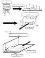
Anhand der Fig. 1A und 1 B wird das Verfahren näher erläutert. Wird das Stückgut in Gebinden, wie Kartons unddgl., angeliefert, dann werden die Einzelpackungen diesen Gebinden entnommen und lose auf eine Transporteinrichtung2 einer Vereinzelungseinheit 3 geschüttet. Eine Vorsortierung der einzelnen Packungen beispielsweise hinsichtlichihrer Größe ist nicht erforderlich. In der Vereinzelungseinheit 3 wird das einzelne Stückgut, beispielsweise Pakkungen,in bekannter Weise vereinzelt. Beispielsweise kann diese Vereinzelung durch Vibrationsförderung erfolgen.Das Stückgut 1 wird dann hintereinander einer Erfassungseinrichtung 4 zugeführt, in der Leseeinrichtungen 5 bis 8,beispielsweise Scanner, vorgesehen sind. Mit diesen Leseeinrichtungen 5 bis 8 kann ein am Stückgut 1 vorgesehenerBarcode gelesen werden. Bei quaderförmigen Packungen 1 befinden sich diese Barcodes üblicherweise an denSchmalseiten, am Boden oder im Deckel. Darum sind die Leseeinrichtungen 5 bis 8 vorteilhaft so angeordnet, daß siediese vier Seiten des Stückgutes 1 erfassen können. Die Leseeinrichtungen 5 bis 8 bzw. die Erfassungseinrichtung 4sind an eine (nicht dargestellte) Rechnereinheit angeschlossen, in der eine Datenbank installiert ist, in welcher sämtlicheverfügbaren Präparate mit ihrer zugehörigen Pharmazentralnummer (Barcode) abgelegt sind.1A and 1B, the method is explained in more detail. Is the general cargo in containers such as boxes andLike., delivered, then the individual packs are removed from these containers and loosely on a transport device2 a separation unit 3 poured. A pre-sorting of the individual packs, for example with regard totheir size is not required. In the separating unit 3, the individual piece goods, for example packs,isolated in a known manner. For example, this separation can be done by promoting vibrations.The
Die Erfassungseinrichtung 4 ist vorteilhaft nahe dem Ende der Transporteinrichtung 2 der Vereinzelungseinheit 3angeordnet. Damit die Leseeinrichtungen 5 bis 8 die entsprechenden Seiten der Packung 1 erfassen können, ist dieTransporteinrichtung 2 in diesem Bereich nach unten und nach außen durch eine durchsichtige Fläche, beispielsweiseeine Glasplatte, unterbrochen. Sobald das Stückgut 1 in diesen durchsichtigen Bereich der Transporteinrichtung 2gelangt, können die Leseeinrichtungen 5 bis 8 die entsprechenden Seiten des Stückgutes 1 erfassen und einen dortvorhandenen Barcode lesen. Anhand dieses Barcodes oder auch durch OCR-Lesung wird die jeweilige Packung 1identifiziert. Diese Identifizierung kann während des Transports oder auch am Ende des Transports erfolgen.The
Sollte die Packung 1 eine ungünstige Lage in bezug auf die Leseeinrichtungen 5 bis 8 aufweisen, so daß derBarcode nicht erfaßt wird, dann erhält der Rechner ein entsprechendes Signal. Dadurch schaltet der Rechner seinerseitseine (nicht dargestellte) Aussortiereinrichtung ein, mit der das nicht identifizierbare Stückgut 1 von der Transporteinrichtung2 zurück zum Beginn der Transporteinrichtung befördert wird. Eine solche Aussortiereinrichtung kann beispielsweiseeine mechanisch arbeitende Abweisklappe sein, die sich im Transportweg des Stückgutes befindet undin dessen Transportweg geschaltet wird, durch welche das Stückgut aus der Transportbahn gelenkt wird. Die Klappekann aber auch im Boden der Transportbahn vorgesehen sein und wegklappen, sobald sich das Stückgut auf ihr oderkurz vor ihr befindet. Es fällt dann beispielsweise auf eine darunter befindliche Rückführeinrichtung, mit der diesesStückgut zum Anfang der Transporteinrichtung 2 zurückgefordert wird. Von dort gelangt es erneut auf die Transporteinrichtung2. Es ist dann davon auszugehen, daß das Stückgut 1 nunmehr in eine solche Lage auf der Transporteinrichtung2 gelangt, daß der Barcode von den Leseeinrichtungen 5 bis 8 erfaßt werden kann. Gegebenenfalls mußdieses Stückgut 1 erneut zum Anfang der Transporteinrichtung 2 zurückgefördert werden.Should the
Das nicht lesbare Stückgut 1 kann beispielsweise auch durch Preßluft, die beispielsweise von unten durch die Transporteinrichtung 2 auf das Stückgut 1 wirkt, von der Transportbahn weggeblasen und auf eine Rückführeinrichtungoder dergleichen gefördert werden.The
Nachdem mittels der Leseeinrichtungen 5 bis 8 das Stückgut 1 identifiziert worden ist, gelangt es beim weiterenTransport zu einer Vermessungseinrichtung 9, mit der das jeweilige Stückgut in seinen Außenabmessungen vermessenwird. Die Vermessung kann elektrisch, elektronisch, mechanisch, mit Ultraschall und dgl. erfolgen. Im dargestelltenAusführungsbeispiel hat die Vermessungseinrichtung 9 optische Meßgeräte 10, die Lichtschranken, Sensoren, Kameras,Ultraschall oder dgl. sein oder mechanisch arbeiten können. Im Ausführungsbeispiel ist die Vermessungseinrichtung9 mit drei CCD-Zeilenkameras ausgestattet, mit denen das Stückgut 1 in seinen drei Koordinaten erfaßt werdenkann. Diese drei Kameras 10 sind in Fig. 1 A symbolisch durch die drei Raumkoordinaten angedeutet. Die drei Kameras10 sind an den Rechner angeschlossen und übermitteln die entsprechenden Meßwerte der Packung 1. Anhand derdrei Abmessungen des Stückgutes 1 kann der Rechner das Volumen des Stückgutes 1 bzw. die Lagerfläche desStückgutes berechnen. So läßt sich die geeignetste Fläche im Hinblick auf die Optimierung des Gesamtlagers berechnen,auf die das Stückgut 1 in der Lagerstellung gelegt werden kann.After the
Im Rechner ist der verfügbare Lagerraum (z.B. Schubladenfläche x Nutzhöhe) eines Lagers 11 (Fig. 1B) gespeichert.Dieses Lager 11 ist beispielsweise ein Schubladenlager, wie es in Apotheken häufig eingesetzt wird. In deneinzelnen Schubladen 12 wird das jeweilige Stückgut gelagert. Anhand der von der Vermessungseinrichtung 9 an denRechner gelieferten Maßangaben überprüft der Rechner, an welcher Lagerstelle das gemessene Stückgut unter optimalerRaumausnutzung untergebracht werden kann. Das Stückgut 1 wird dann in noch zu beschreibender Weise andiese Lagerstelle gebracht. Der Rechner erhält dann ein entsprechendes Signal, daß diese Lagerstelle nunmehr besetztist. Zudem ist infolge der Erfassungseinrichtung 4 der Rechner auch darüber informiert, welches Produkt sich andieser Lagerstelle befindet. Wird darum dieses Produkt später vom Apotheker angefordert, kann es von einem entsprechendenHandhabungsgerät dem Lager 11 entnommen werden. Dabei erhält der Rechner wiederum ein Signal,daß diese Lagerstelle wieder frei ist. Außerdem wird der Rechner dann auch darüber informiert, daß ein bestimmtesPräparat entnommen worden ist. Auf diese Weise ist auch jederzeit eine kontinuierliche Bestandsführung der Präparategewährleistet. Das entsprechende Programm des Rechners ist vorteilhaft so ausgebildet, daß beispielsweise bei einemvorgegebenen Minimalbestand des jeweiligen Präparates automatisch ein Bestellformular ausgedruckt wird, das vomApotheker nur noch abzuzeichnen ist. Auf diese Weise ist sichergestellt, daß die Präparate stets in der Apothekevorrätig sind.The available storage space (e.g. drawer area x usable height) of a storage 11 (FIG. 1B) is stored in the computer.This
Das Lager 11 ist vorteilhaft CNC-gesteuert. Hierzu ist das Lager 11 an den Rechner angeschlossen. Mit ihm wirddie jeweilige Schublade 12 ausgefahren, in der sich die für das Stückgut 1 vorgesehene freie Lagerstelle befindet.The
Als Lager 11 kann ein überdimensionaler Schubladenschrank verwendet werden, dessen Schubladen 12 beispielsweisemittels Teleskopstangen ein- und ausgefahren werden. Als Antriebe für die Schubladen 12 können Zahnstangentriebe,Pneumatik- oder Hydraulikantriebe und dergleichen eingesetzt werden, die jeweils über den Rechnergesteuert betätigt werden. Dadurch ist ein vollautomatisches Be- und Entladen der Schubladen möglich. Zum Be- undEntladen des Lagers 11 ist ein Handhabungsgerät 13 vorgesehen, das vorzugsweise ein n-achsiger Roboter ist. Einsolcher Roboter kann ein Portalroboter oder ein herkömmlicher Roboter mit mehreren Bewegungsachsen sein. In Fig.3 ist ein bevorzugtes Ausführungsbeispiel eines Handhabungsgerätes in Form eines Portalroboters dargestellt. Ernimmt nur wenig Platz in Anspruch und hat kurze Zugriffszeiten. Der Portalroboter 13 hat zwei im Bereich neben demLager 11 angeordnete Führungsschienen 14 und 15, auf denen ein Querträger 16 verfahrbar ist. Er erstreckt sichzwischen den beiden Führungsschienen 14 und 15 und liegt im Bereich oberhalb des Regals 11. Auf den Führungsschienen14, 15 kann der Querträger 16 in Verschieberichtung der Schubladen 12 verfahren werden.An oversized drawer cabinet, the
Längs des Querträgers 16 ist ein senkrecht zu ihm sich erstreckender Vertikalträger 17 verfahrbar, längs dem inHöhenrichtung eine (nicht dargestellte) Greifeinrichtung verfahrbar ist. Mit ihr kann das Stückgut der jeweiligen Schublade12 entnommen bzw. in der Schublade abgelegt werden. Der Portalroboter 13 ist an den Rechner angeschlossenund wird durch ihn so gesteuert, daß die Greifeinrichtung die jeweilige Lagerstelle anfährt.A
Die Schublade 12 des Lagers 11 ist längs Führungsschienen 18 und 19 mit den beschriebenen Antrieben verfahrbar.Über den Rechner wird die jeweils ein- bzw. auszufahrende Schublade 12 angesteuert und bevorzugt nur so weitausgefahren, bis die jeweilige Lagerstelle im Griffbereich der Greifeinrichtung des Portalroboters 13 liegt. Befindet sichdiese Lagerstelle in der Nähe der Blende der Schublade 12, dann muß sie nur wenig aus dem Lager 11 ausgefahrenwerden, wodurch erheblich Zeit eingespart wird.The
Die Transporteinrichtung 2, auf der die Stückgüter 1 nacheinander durch die Vereinzelungseinheit 3, die Erfassungseinrichtung4 und die Vermessungseinrichtung 9 transportiert werden, erstreckt sich so weit, daß die Stückgütervon der Greifeinrichtung des Portalroboters 13 ergriffen werden können.The
Anstelle der beschriebenen Schubladen kann das Lager 11 auch jede andere geeignete Ablage aufweisen. Beispielsweisekönnen Ablagen eingesetzt werden, die um eine vertikale Achse dreh- oder schwenkbar sind.Instead of the drawers described, the bearing 11 can also have any other suitable storage. For exampleshelves can be used that can be rotated or swiveled around a vertical axis.
Aufgrund der Vermessung des Stückgutes 1 in der Vermessungseinrichtung 9 ist die örtliche Lage und die dreidimensionaleGröße des Stückgutes 1 relativ zur Transportrichtung bekannt. Die Datenbank des Rechners stellt nunmehreine Zuordnung zwischen der Packungsgröße in den ihr eigenen und durch die Vermessung bekannten drei Dimensionen und dem Produkt selbst mit seiner zugehörigen Pharmazentralnummer (Barcode) sowie deren Lage und Positionauf der Packung her. Der Rechner erhält entsprechende Signale, aufgrund derer er der Greifeinrichtung desPortalroboters 13 entsprechende Steuersignale übersendet. Die Greifeinrichtung wird dann in bezug auf das zu fassendeStückgut 1 eingestellt. So wird bei einer entsprechend großen Packung die Öffnungsweite der Greiffinger entsprechendgroß eingestellt. Auch der Greifdruck kann variiert werden, je nachdem, ob das Stückgut weich oder hartist. Wenn darum die Greifeinrichtung des Portalroboters 13 an das Stückgut 1 herangefahren ist, nimmt die Greifeinrichtungbereits die zum Fassen des Stückgutes 1 erforderliche Lage ein, so daß es mühelos erfaßt werden kann.Due to the measurement of the
Je nach den beiden Meßergebnissen wird somit die geometrische Position des Stückgutes 1 berechnet, die Lagerflächeund Lagerseite festgestellt, die Griffseite und Griffposition für die Greifeinrichtung bestimmt und die jeweiligeSchublade 12 sowie die Lagekoordinaten in der Schublade berechnet.Depending on the two measurement results, the geometric position of the piece good 1 is calculated, the storage areaand bearing side determined, the handle side and handle position determined for the gripping device and the
Am Ende der Transporteinrichtung 2 wird somit das jeweilige Stückgut 1 vom Portalroboter 13 erfaßt und an dievom Rechner bestimmte Lagerstelle in der entsprechenden Schublade 12 lagegerecht abgelegt. Solange die Greifeinrichtungdas Stückgut 1 aufnimmt und in Richtung auf das Lager 11 transportiert, wird, vom Rechner gesteuert,bereits die entsprechende Schublade 12 in der erforderlichen Länge ausgefahren, so daß die Greifeinrichtung sofortdas Stückgut ablegen kann.At the end of the
Das Handhabungsgerät 13 kann anstelle einer Greifeinrichtung auch eine Saugeinrichtung aufweisen, mit der dasjeweilige Stückgut durch Ansaugen festgehalten wird.Instead of a gripping device, the handling
In den Fig. 2A bis 2C wird beispielhaft das Einlagern unterschiedlich großer Stückgüter 1 erläutert. In Fig. 2A isteine Schublade 12' dargestellt, deren Blende 20 nur eine geringe Höhe a hat. Daraus ergibt sich, daß die Stückgüter1 in dieser Schublade nur so gelagert werden können, daß ihr in Höhenrichtung der Schublade 12' gemessenes Maßap kleiner als die Höhe a der Blende 20 ist. Der Rechner, dem die Abmessungen der Schublade 12' bekannt sind,ermittelt somit die Position des Stückgutes 1 so, daß es in dieser Schublade 12' gelagert werden kann. So ist erkennbar,daß das Stückgut 1' in der Schublade 12' nur so abgelegt werden kann, daß es mit seiner Breitseite auf der Schubladenflächeliegt. Hochkant kann das Stückgut 1' in dieser Schublade 12' nicht gelagert werden. Dementsprechend sindauch die schematisch in Fig. 2A dargestellten weiteren Stückgüter so abgelegt, daß ihre in vertikaler Richtung gemessenenMaße geringer sind als das Maß a der Blende 20.2A to 2C, the storage of items of
Fig. 2B zeigt eine Schublade 12", deren Blende 20" die Höhe b hat, die größer ist als die Höhe a der Blende 20gemäß Fig. 2A. Dementsprechend können in dieser Schublade 12" größere Stückgüter 1 gelagert werden. Auch siemüssen aber so in der Schublade 12" abgelegt werden, daß ihre in vertikaler Richtung gemessenen Abmessungenap kleiner sind als die Höhe b der Blende 20". Die Greifeinrichtung des Portalroboters 3 wird durch den Rechnerwiederum so gesteuert, daß das Stückgut so in der Schublade 2" abgelegt wird, daß es nicht über die Blende 20"übersteht.FIG. 2B shows a
Die Schublade 12"' gemäß Fig. 2C schließlich hat die größte Höhe c. Darum können in ihr die größten Stückgüteruntergebracht werden. Auch hier müssen die Stückgüter so abgelegt werden, daß ihr in Vertikalrichtung gemessenesMaß ap geringer ist als die Höhe c der Blende 20"'.Finally, the
Wie sich aus den Fig. 2A bis 2C ergibt, werden die Stückgüter nicht alphabetisch oder nach Warengruppen abgelegt,wie dies üblicherweise der Fall ist. Ablageprinzip ist ausschließlich die Packungsgröße bzw. die belegte Lagerflächedes Stückgutes 1. Der Rechner kann aus den Abmessungen der jeweiligen Schubladen die Lagerfläche bzw.das Lagervolumen berechnen und die anfallenden Stückgüter so den einzelnen Schubladen zuordnen, daß eine optimaleFlächennutzung mit den Stückgütern gewährleistet ist. Da der Rechner die Art des Produktes, dessen Namen,dessen Größe und auch dessen Lagerstelle in der jeweiligen Schublade kennt, ist gewährleistet, daß der Apothekerjederzeit auf Abruf das erforderliche Präparat in noch zu beschreibender Weise automatisch erhält. Mit der Greifeinrichtungdes Portalroboters 13 lassen sich die einzelnen Stückgüter auch einfach an bereits lagemde Packungen beioptimaler Flächennutzung in der jeweiligen Schublade ablegen.2A to 2C, the piece goods are not stored alphabetically or according to product groups,as is usually the case. The storage principle is only the package size or the occupied storage spaceof the
Mit der beschriebenen Vorrichtung und dem beschriebenen Verfahren wird es möglich, auf einer vorgegebenenGrundfläche ein maximales Lagervolumen durch die Übereinanderanordnung möglichst vieler Lagerflächen zu erreichen.Dazu ist es erforderlich, den Abstand zwischen den Lagerstellen zu minimieren. Zu diesem Zweck wird diejeweils kleinste Seitenlänge des Stückgutes 1 als Höhenmaß herangezogen, so daß dementsprechend die jeweilsgrößeren Seitenlängen die Lagerfläche des Stückgutes bilden. Auf diese Weise können die Lagerstellen niedrigerSchubladen optimal ausgenutzt werden. Sollten die Lagerstellen der niedrigen Schubladen belegt sein, wird das Stückgut,das an und für sich für eine niedrige Schublade vorgesehen ist, in einer höheren Schublade unter Ausnutzungeiner möglicherweise kleineren Lagerstelle abgelegt.With the described device and the described method it is possible to operate on a predeterminedFloor space to achieve a maximum storage volume by stacking as many storage areas as possible.This requires minimizing the distance between the bearing points. For this purpose thethe smallest side length of the piece good 1 is used as the height dimension, so that the respectivelarger side lengths form the storage area of the piece goods. This way the bearings can be lowerDrawers are used optimally. If the storage locations of the low drawers are occupied, the general cargo,which in and of itself is intended for a low drawer, in a higher drawer using ita possibly smaller depository.
Im folgenden wird beispielhaft eine Flächenbedarfsermittlung für das Lager 11 beschrieben. Hierbei wird davonausgegangen, daß in einer Apotheke durchschnittlich 8000 Artikel erhältlich sind. Diese Artikel können in Kategorien1 bis 5 hinsichtlich ihrer Stückzahl in einer Apotheke eingeteilt werden. In die Kategorie 1 fallen Artikel, die der Apothekerbeispielsweise 30 mal zur Verfügung hat (30 Einheiten). Durchschnittlich sind dies 0,5 % der angenommenen 8000Artikel. Hieraus ergibt sich, daß der Apotheker 1200 dieser Artikel (Stückgüter) in der Apotheke zur Verfügung hat. Inder Kategorie 2 sind durchschnittlich 15 Einheiten des Artikels vorhanden. Die Kategorie 2 macht durchschnittlich 1 % der 8000 Artikel aus, so daß sich in der Apotheke ebenfalls 1200 Stück dieser Artikel befinden (80 x 15). Die Kategorie3 umfaßt solche Artikel, die der Apotheker durchschnittlich 5 mal auf Lager hat. Diese Kategorie 3 macht durchschnittlich2 % der 8000 Artikel aus, woraus sich eine Stückzahl von 800 (160 x 5) ergibt. Die Kategorie 4, zu der solcheArtikel zählen, die der Apotheker durchschnittlich nur zweimal auf Lager hat, macht etwa 5 % der Gesamtartikel aus.Somit ergibt sich für die Kategorie 4 eine Stückzahl von 800 (400 x 2). 91,5 % der 8000 Artikel fallen in die Kategorie5, d.h. der Apotheker hat diese Produkte nur einmal auf Lager. Somit beträgt die Stückzahl der Kategorie 5 7320 (7320x 1). Berücksichtigt man alle Kategorien 1 bis 5, so ergibt dies eine Artikelzahl von 11320, d.h. der Apotheker mußdurchschnittlich diese Stückzahl in seinem Lager unterbringen.An area requirement determination for the
Werden die beiden größeren Seiten einer quaderförmigen Packung (Stückgut) als Lagerflächenseiten herangezogen,dann ergibt sich eine durchschnittliche Flächengröße pro Produkt von 5 cm x 7 cm = 35 cm2. Wird hierzu nochbeispielsweise jeweils ein 4 mm breiter Zwischenraum zur nächsten Packung als Greifraum hinzugerechnet, ergibtsich eine Fläche von 46 cm2. Weiter muß ein durchschnittlicher Flächenverlust bei der Lagerungsoptimierung vonbeispielsweise 15 % berücksichtigt werden. Daraus ergibt sich eine durchschnittliche Flächengröße von 53 cm2. Die11320 Artikel beanspruchen somit eine Gesamtlagerfläche von 53 cm2 x 11320 = 60 m2. In einer Apotheke durchschnittlicherGröße muß darum eine solche Lagerfläche von 60 m2 zur Verfügung stehen.If the two larger sides of a cuboid pack (piece goods) are used as storage surface sides, this results in an average surface area per product of 5 cm x 7 cm = 35 cm2 . If, for example, a 4 mm wide space is added to the next pack as a gripping space, this results in an area of 46 cm2 . Furthermore, an average loss of area in the storage optimization of, for example, 15% must be taken into account. This results in an average area size of 53 cm2 . The 11320 articles thus take up a total storage area of 53 cm2 x 11320 = 60 m2 . In a pharmacy of average size, such a storage area of 60 m2 must be available.
Aus diesem Lagerflächenbedarf läßt sich sehr einfach eine Nutzhöhenbedarfsermittlung für das Lager 11 berechnen.Hierbei wird die kleinste Kantenlänge einer Packung 1 als Parameter herangezogen. Bei der folgenden Berechnungwird angenommen, daß die 11320 Stückgüter gleichmäßig in 32 Schubladen 12 mit jeweils einer Grundflächevon 2 m2 verteilt eingelagert werden. Die Schubladen 12 sollen in fünf Typen A bis E unterteilt sein, wobei der SchubladentypA ein Höhenrastermaß von 45 mm, der Schubladentyp B von 60 mm, der Schubladentyp C von 75 mm, derSchubladentyp D von 90 mm und der Schubladentyp E von 110 mm hat. Dieses Höhenrastermaß ergibt sich aus demNutzmaß sowie einer Zulage von 30 mm für die Konstruktion der Schublade, den lichten Abstand sowie für ein Vakuumbodensystemin den Schubladen, das unten noch näher erläutert werden soll. Zieht man dieses Zumaß von 30 mmab, dann steht eine Nutzhöhe bei den Schubladentypen A bis E von 15 mm bis 80 mm zur Verfügung. Die Verpakkungsgrößenin einer Apotheke können sich beispielsweise wie folgt aufteilen:
Umgerechnet auf eine Gesamtstückzahl von 11320 ergibt sich somit folgende Präparateanzahl:
Diejenigen Präparate, die eine kleinste Kantenlänge von bis zu 15 mm haben, lassen sich im Schubladentyp Aunterbringen. Entsprechend lassen sich die Präparate mit einer kleinsten Kantenlänge von 15 bis 30 mm im SchubladentypB, von 30 bis 45 mm im Schubladentyp C, von 45 bis 60 mm im Schubladentyp D und von 60 bis 80 mm imSchubladentyp E unterbringen. Daraus ergibt sich unter Berücksichtigung der durchschnittlichen Flächengröße derProdukte von 53 cm2 folgende benötigte Lagerfläche in den verschiedenen Schubladentypen:
Die Schubladenflächen ergeben somit eine Gesamtfläche von 60 m2. Aus der Rasterhöhe und der Schubladenfläche ergibt sich somit ein Nettokonstruktionsvolumen der Schubladen von 3,44 m3.The drawer areas thus result in a total area of 60 m2 . The grid height and the drawer area thus result in a net construction volume of the drawers of 3.44 m3 .
Auf diese Weise kann das Lager 11 optimal zur Lagerung der unterschiedlichsten Stückgüter 1 genutzt werden.Mit der Erfassungseinrichtung 4 wird das Stückgut 1 identifiziert. Anhand der Vermessung des Stückgutes 1 in derVermessungseinrichtung 9 berechnet der Rechner unter Berücksichtigung des freien Lagerplatzes im Lager 11, inwelcher Lage das Stückgut 1 in der jeweiligen Schublade 12 untergebracht werden kann, um eine optimale Flächenausnutzungzu ermöglichen. Dementsprechend wird die Greifeinrichtung des Portalroboters 13 gesteuert, damit siedas Stückgut 1 von der Transporteinrichtung 2 abnehmen und in der richtigen Lage an der ausgewählten Lagerstelleablegen kann. Als Ordnungsmaßstab dient somit nicht mehr beispielsweise der Produktname oder die Produktart,sondem ausschließlich die Packungsgröße. Dadurch kann der Lagerraum erheblich verringert werden im Vergleichzur herkömmlichen Lagerung solcher Produkte, die ohne Rücksicht auf die Packungsgröße lediglich alphabetisch nachdem Produktnamen oder nach der Zusammengehörigkeit von Produktart bzw. Produktsorte gelagert werden. Da dieLagerung vollständig rechnergesteuert und vollautomatisch erfolgt, ist jederzeit sichergestellt, daß der Apotheker dasvon ihm gewünschte Produkt zuverlässig erhält. Er ist an seiner Verkaufstheke mit einer entsprechenden Computereinheitausgestattet, die an den Rechner direkt oder beispielsweise ferngesteuert angeschlossen ist. Über sie gibt derApotheker die entsprechenden Befehle oder Namen ein, damit ein entsprechendes Produkt aus dem Lager 11 geholtwird. Der zentrale Rechner gibt dann ein entsprechendes Signal an die Greifeinrichtung sowie an die Steuerung dereinzelnen Schubladen 12, so daß diese ausfahren und die Greifeinrichtung das angeforderte Stückgut 1 ergreifen undentnehmen kann.In this way, the
Es ist auch möglich, den Abstand zwischen den Ablagen zu verändern, so daß eine Anpassung an das größteHöhenmaß des Stückgutes 1 möglich ist. Die Ablageflächen können hierzu vertikal verschiebbar angeordnet sein.It is also possible to change the distance between the shelves, so that an adaptation to the largestHeight of the
Damit beim Verschieben der Schubladen 12 das darin gelagerte Stückgut nicht verrutscht, sind sie mit einerRutschsicherung versehen. Sie kann eine rutschfeste Oberseite des Bodens 21 der Schublade sein. Im dargestelltenAusführungsbeispiel werden die Stückgüter mittels Unterdruck gegen Verrutschen gesichert. Hierzu ist der Boden 21(Fig. 3) der jeweiligen Schublade 12 mit Öffnungen 22 versehen, durch die Luft angesaugt werden kann. Die Verpakkungenwerden dadurch gegen den Schubladenboden 21 mittels Unterdruck gezogen, so daß sie beim Ein- und Ausfahrender Schublade 12 nicht verrutschen. Hierfür reicht ein verhältnismäßig geringer Unterdruck aus, der in herkömmlicherWeise mit Pumpen und dergleichen erzeugt werden kann. Im Bereich unterhalb des Bodens 21 ist dieSchublade 12 mit einer entsprechenden Saugkammer versehen, aus der zur Erzeugung des Unterdruckes in bekannterWeise Luft abgesaugt wird.So that the piece goods stored therein do not slip when the
Damit die vom Apotheker gewünschten Präparate vom Lager 11 zur Verkaufsstelle transportiert werden, ist eine(nicht dargestellte) Warentransporteinrichtung vorgesehen, die das ausgewählte Produkt vorteilhaft unmittelbar bis andie Verkaufstheke heranfördert. Diese Warentransporteinrichtung hat beispielsweise ein Förderband, auf dem der Portalroboter13 das jeweilige Stückgut 1 ablegt. Die Breite dieses Förderbandes ist auf die kürzeste Seitenlänge desStückgutes 1 mit der größten kürzesten Seite abgestimmt. Vorteilhaft ist das Förderband U-förmig ausgebildet, so daßdas Stückgut nicht vom Förderband fallen kann.So that the preparations desired by the pharmacist are transported from the
Das Förderband ist vorteilhaft in einem Rohr untergebracht, das zweckmäßig im Deckenbereich verläuft. DiesesRohr kann oberhalb einer abgehängten Decke angeordnet sein, so daß es von außen nicht sichtbar ist. Dieses Transportrohrwird so geführt, daß es vom Arbeitsbereich des Portalroboters 13 bis zu einem Fallrohr 23 verläuft (Fig. 4),das sich beispielsweise bis zur Verkaufstheke erstreckt. Am Eintritt in das Fallrohr oder noch innerhalb des Transportrohresist vorteilhaft eine Lichtschranke oder dergleichen eingebaut, mit der die Ankunft einer Packung festgestelltwerden kann. Dann kann ein entsprechendes Signal im Verkaufsraum ausgelöst werden. Anstelle des beschriebenenFörderbandes können beispielsweise auf Schienen oder auf andere Weise geführte, miniaturisierte fahrerlose Transportsystemeeingesetzt werden.The conveyor belt is advantageously accommodated in a tube which expediently runs in the ceiling area. ThisPipe can be arranged above a suspended ceiling, so that it is not visible from the outside. This transport pipeis guided in such a way that it extends from the working area of the
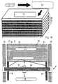
Damit das Stückgut 1 nicht ungebremst durch das Fallrohr 23 nach unten fällt, ist es mit einer Bremseinrichtungversehen. Das Fallrohr 23 hat vorzugsweise kreisförmigen Querschnitt. Zur Bildung der Bremseinrichtung sind in dasFallrohr 23 zwei dehnbare Trennwände 24 und 25 eingesetzt, die parallel zueinander verlaufen und zwischen sicheinen Förderkanal 26 für das Stückgut 1 bilden. Zwischen den Trennwänden 24, 25 und dem Fallrohr 23 werden imQuerschnitt segmentförmige Luftkammern 27 und 28 gebildet, in die Luftzuleitungen 29 und 30 münden. Über sie wirddosiert Luft in die Kammern 27, 28 geblasen, wobei die Trennwände 24, 25 entsprechend dem Luftdruck elastischgedehnt werden. Das durch den Kanal 26 fallende Stückgut 1 dehnt die Trennwände 24, 25 beim Durchfallen geringfügiggegen den Druck in den Kammern 27, 28 und wird somit gebremst. Der Druck in den Kammern 27, 28 wird soan das durchfallende Stückgut angepaßt, daß es mit einer ausreichenden Geschwindigkeit nach unten fällt.So that the
Die Fallgeschwindigkeit kann sehr einfach beispielsweise durch zwei einander gegenüberliegende, an der Innenwandungdes Fallrohres 23 im Förderkanal 26 sitzende Fotosensoren 31, 32 bestimmt werden. Ist die Fallgeschwindigkeitzu hoch, dann wird über die Luftzuleitungen 29, 30 Luft in die Kammern 27, 28 geleitet, wodurch die Trennwände24, 25 mehr gedehnt werden (gestrichelte Linien in Fig. 4) und der Durchlaßquerschnitt des Kanals 26 verringert wird.Das Stückgut 1 wird auf diese Weise in seiner Fallgeschwindigkeit verringert.The falling speed can be very easily, for example, by two opposing, on the inner wallof the
Ist umgekehrt die Fallgeschwindigkeit zu gering, dann wird der Druck in den Kammern 27, 28 entsprechend verringert.Conversely, if the falling speed is too low, the pressure in the
Bei einer anderen (nicht dargestellten) Ausführungsform besteht die Bremseinrichtung aus zwei ineinander liegendenSchläuchen, die vorteilhaft aus einer glatten Folie gebildet sind. Der Innendurchmesser des inneren Schlaucheswird an die Größe des Stückgutes 1 angepaßt. In den Ringraum zwischen den beiden Schläuchen wird dosiertLuft geblasen oder abgesaugt. Dadurch läßt sich der Innendurchmesser des inneren Schlauches einfach an die Größeund an das Gewicht des Stückgutes 1 anpassen. Das Stückgut 1 rutscht im inneren Schlauch gebremst nach unten.Der Innendurchmesser des inneren Schlauches ist geringfügig kleiner als die Packungsgröße. Aufgrund des Luftpolstersim Ringraum zwischen den beiden Schläuchen wird beim Hindurchfallen des Stückgutes 1 der innere Schlauchentsprechend geringfügig aufgeweitet. Lichtschranken im Fallrohr können wiederum die Fallgeschwindigkeit des Produktesverfolgen und über den Rechner bedarfsgerecht die Luftbremsung dosieren.In another (not shown) embodiment, the braking device consists of two nestedHoses, which are advantageously formed from a smooth film. The inside diameter of the inner tubeis adapted to the size of the
Das Fallrohr kann auch innen mit Klappen versehen sein, die elektromagnetisch geladen werden können. DurchDosierung des Stroms kann die Durchrutschgeschwindigkeit des Stückgutes 1 bestimmt werden. Diese elektromagnetischeVariante erlaubt somit ebenfalls ein gebremstes Fördern des Stückgutes 1 im nach unten sich erstreckendenFallrohr.The downpipe can also be provided on the inside with flaps that can be charged electromagnetically. ByDosage of the current, the slipping speed of the
Das Stückgut kann aus dem Fallrohr in eine Aufnahme gefördert werden, aus welcher der Apotheker das Stückgutbequem herausnehmen kann. Es ist aber auch möglich, das Stückgut innerhalb des Fallrohres festzuhalten. Hierzuist im Fallrohr ein quer zur Achse des Fallrohres bewegliches Klemmstück vorgesehen, das durch Strombeaufschlagungverstellt werden kann. Diesem Klemmstück gegenüber kann ein Widerlager im Fallrohr angeordnet sein. Rutschtdas Stückgut 1 im Fallrohr nach unten, dann kann kurz vor dem Klemmstück eine Lichtschranke oder dergleichenvorgesehen sein. Passiert das Stückgut 1 diese Lichtschranke, wird ein Impuls ausgelöst, mit dem der Antrieb desKlemmstückes eingeschaltet wird. Es wird dann in Richtung auf das gegenüberliegende Widerlager verschoben, wodurchdas Stückgut 1 zwischen ihm und dem Widerlager festgeklemmt wird. Das Fallrohr kann in Höhe dieser Klemmeinrichtungeine Klappe oder dergleichen aufweisen, so daß das Stückgut entnommen werden kann.The general cargo can be conveyed out of the downpipe into a receptacle from which the pharmacist removes the general cargocan be easily removed. However, it is also possible to hold the piece goods within the downpipe. For thisa clamping piece that is movable transversely to the axis of the downpipe is provided in the downpipe, which is applied by currentcan be adjusted. Opposed to this clamping piece, an abutment can be arranged in the downpipe. Slipsthe
Eine solche Klemmeinrichtung kann aber auch in einem Transportwagen oder dergleichen vorgesehen sein, dersich unterhalb des Fallrohres befindet. Dann kann der Transportwagen unter dem Fallrohr weggefahren werden, sodaß sich das Stückgut bequem entnehmen läßt.Such a clamping device can also be provided in a trolley or the likeis located below the downpipe. Then the trolley can be moved away under the downpipe, sothat the general cargo can be removed easily.
Aufgrund der vollautomatischen Lagerung ist es vorteilhaft möglich, die abgelegten Stückgüter 1 umzulagern, umeine Optimierung der Lagerstellen zu gewährleisten. Eine solche Umlagerung wird zweckmäßig während der Ruhepausenin der Apotheke, bsp. in der Mittagspause oder über Nacht, durchgeführt, so daß der Apothekenbetrieb nichtgestört wird.Because of the fully automatic storage, it is advantageously possible to relocate the stored
Wird bei der Vermessung des Stückgutes 1 festgestellt, daß es in seinen Abmessungen zu groß ist und darumnicht in die im Lager 11 vorgesehenen Schubladen gelegt werden kann, wird ein entsprechendes Signal an den Rechnergeschickt, der dann seinerseits ein Signal an das Handhabungsgerät 13 oder ein anderes Handhabungsgerät sendet,um das zu große Stückgut 1 auszusortieren. Auch ist es möglich, insbesondere wenn die Vermessung des Stückgutes1 während des Transportes erfolgt, im Transportweg eine Sortierweiche vorzusehen, mittels der das zu große Stückgut1 einfach aussortiert werden kann.It is found when measuring the
Mit der beschriebenen Einrichtung ist auch eine Wareneingangskontrolle sehr einfach möglich. Die ankommendenStückgüter werden in der beschriebenen Weise auf die Transporteinrichtung 2 geschüttet und mittels der Vereinzelungseinheit3 vereinzelt. Dann durchläuft jedes einzelne Stückgut die Erfassungseinrichtung 4, in der jedes einzelneStückgut zuverlässig erfaßt wird. Der Rechner kann dann die übermittelten Werte mit einer Wareneingangsliste vergleichen,so daß mühelos eine Wareneingangskontrolle gewährleistet ist.With the described device, an incoming goods inspection is also very easy. The arrivingGeneral cargo is poured onto the
Gleichzeitig ist es möglich, das sogenannte "first in - first out"-Verfahren zu gewährleisten. Damit wird das ältestegelagerte bzw. eingegangene Stückgut eines Artikels auch als erstes entnommen.At the same time, it is possible to guarantee the so-called "first in - first out" process. It will be the oldestStored or received piece goods of an article are also removed first.
In der Erfassungseinrichtung 4 kann auch das an der Verpackung des Stückgutes 1 vorhandene Verfallsdatumerfaßt und dem Rechner mitgeteilt werden. Dieses Verfallsdatum kann dann als Kriterium für die Herausgabe desStückgutes 1 aus dem Lager 11 dienen. Wird ein Stückgut 1 vom Apotheker angefordert, das mehrfach im Regal 11vorhanden ist, dann weist der Rechner das Handhabungsgerät 13 an, das vom Verfallsdatum her älteste Stückgut 1dem Lager 11 zu entnehmen und dem Apotheker in der beschriebenen Weise zuzuführen. Dem Rechner ist die Lagerstelleaufgrund der beschriebenen Erfassung bekannt, so daß der Rechner auch darüber informiert ist, welchesVerfallsdatum das jeweilige Produkt hat. Somit hat der Apotheker die Gewähr dafür, daß das jeweils älteste Stückguteiner Sorte dem Lager 11 entnommen wird. Dadurch wird auch gewährleistet, daß das Verfallsdatum nicht oder nurin wenigen Fällen, wenn beispielsweise das Produkt nicht vom Kunden gekauft wird, verfällt. Ebenso ist es möglich,alle vom Verfall bedrohten Stückgüter nach Bedarf oder automatisch auszusortieren.The expiry date on the packaging of the
Schließlich ist in der beschriebenen Weise ohne weiteres eine vollautomatische Inventur möglich, da aus demRechner jederzeit der augenblickliche Warenbestand abgerufen werden kann. Darum entfällt für den Apotheker dersehr zeitaufwendige Inventurvorgang; er kann nunmehr automatisch vom Rechner vorgenommen werden. Er kann soprogrammiert sein, daß er eine entsprechende Inventurliste mit Angabe der jeweiligen Präparate, der Zahl der Präparateund dgl. ausdruckt.Finally, a fully automatic inventory is easily possible in the manner described, since from theCalculator the current inventory can be called up at any time. That is why the pharmacist does not need thevery time-consuming inventory process; it can now be carried out automatically by the computer. He can do thatbe programmed so that he has a corresponding inventory list with details of the respective preparations, the number of preparationsand the like.
Anstelle der beschriebenen rechnergestützten automatischen Vermessung und Identifizierung, welche die bevorzugteVorgehensweise ist, ist es aber auch möglich, die Stückgüter 1 von Hand über eine optische Lese- und Vermessungseinrichtungzu führen. Diese Einrichtungen geben dann entsprechende Signale an den Rechner. Die Bedienungspersonlegt anschließend die Stückgüter beispielsweise auf eine Transporteinrichtung, von der sie in der beschriebenenWeise von einem Handhabungsgerät abgenommen und eingelagert werden. Auch können die Stückgütervon Hand eingelagert werden, wie beschrieben worden ist.Instead of the described computer-aided automatic measurement and identification, which is the preferred oneThe procedure is, but it is also possible, the
Die Stückgüter 1 können aber auch von Hand vermessen und/oder identifiziert werden. Die ermittelten Datenwerden dann über eine Tastatur in den Rechner gegeben. Er ermittelt die für das jeweilige Stückgut optimale Lagerstelle.Die Ablage des Stückgutes erfolgt, wie zuvor im einzelnen beschrieben.The
Es ist auch eine Ausführungsform möglich, bei der die Stückgüter 1 nicht mittels des Handhabungsgerätes, sondernmanuell eingelagert oder herausgenommen werden. Damit die Bedienungsperson die vom Rechner ermittelteLagerstelle erkennt, sind verschiedene Einrichtungen möglich. So kann der Rechner eine Zeigereinrichtung steuern,die mit einem Lichtzeiger arbeitet, der die gewählte Lagerstelle anleuchtet.An embodiment is also possible in which the
Die Schubladen oder andere Ablagen können mit Leuchtanzeigen, beispielsweise LEDs, ausgestattet sein, dievom Rechner angesteuert werden. So kann jede Schublade an ihrer Blende mit einer Leuchtanzeige versehen sein,so daß die Bedienungsperson am Aufleuchten der entsprechenden Leuchtanzeige einfach erkennen kann, welcheSchublade zum Ablegen des jeweiligen Stückgutes 1 vorgesehen ist. Um nun in der Schublade die entsprechendeLagerstelle zu kennzeichnen, kann der Schubladenboden mit in zueinander senkrecht liegenden Reihen von Leuchtanzeigenversehen sein, die in einem geeigneten Rasterabstand voneinander angeordnet sind. Durch Aufleuchten derentsprechenden Anzeigen wird die vom Rechner bestimmte Lagerstelle eindeutig angezeigt.The drawers or other shelves can be equipped with light indicators, for example LEDs, whichcontrolled by the computer. So each drawer can be provided with a light indicator on its cover,so that the operator can easily recognize which light from the corresponding light indicatorDrawer for storing the
Es ist aber auch möglich, daß die Lagerstelle in der Schublade nicht durch die Leuchtanzeigen, sondern durcheinen Lichtzeiger angegeben wird, der vom Rechner gesteuert wird.But it is also possible that the bearing in the drawer not by the light indicators, but bya light pointer is specified that is controlled by the computer.
Anstelle der beschriebenen bevorzugten Vereinzelung der Stückgüter 1 mittels der Vereinzelungseinheit 3 könnendie Stückgüter lediglich auf eine Ablage geschüttet werden. Wird als Lager ein Schubladenregal eingesetzt, dann kannals Ablage eine der Schubladen, vorzugsweise eine unterste Schublade, herangezogen werden. Sie wird vorteilhaftnach hinten ausgefahren, so daß die Stückgüter 1 wahllos in diese Schublade geschüttet werden können. Vorteilhaftwerden die Stückgüter in der Schublade noch etwas verteilt. Die Schublade wird anschließend nach vom ausgefahren.Die Greifeinrichtung des Handhabungsgerätes 13 ist mit einer optischen Erfassungseinrichtung versehen, die vorteilhafteine Kamera ist. Sie ist vorzugsweise beweglich an der Greifeinrichtung angeordnet, so daß sie die in der Schubladebefindlichen Stückgüter von mehreren Seiten erfassen kann. Mit einer solchen Erfassungseinrichtung kann dasStückgut vermessen und/oder identifiziert werden. Mit ihr ist es auch möglich, das Verfallsdatum zu lesen. Sollte dasStückgut ungünstig liegen, so daß beispielsweise der Barcode nicht lesbar ist, dann ergreift die Greifeinrichtung dasStückgut und dreht es so weit, daß der Barcode, das Verfallsdatum oder dgl. gelesen werden kann. Anschließendkann dieses Stückgut auf die beschriebene Weise abgelegt werden.Instead of the described preferred separation of the
Claims (9)
- A method of storing goods items (1) at a storage point (12) in a store (11) with storagepoints (12) of different height which are restricted in height and are arranged one abovethe other, in which the item (1) is measured, the dimensions(ap) of the item (1) beingused as the measuring size;in which the item (1) is identified;in which the dimensions(ap) are supplied in the form of a signal to a computer;in which, with reference to the said signal, an appropriate storage point (12) isselected, at which, taking into consideration the storage height, the respective item (1)is deposited with regard to optimum utilization of the space of the store (11);in which the store (11) used is in the form of a shelf or a drawer-type store;in which the goods items (1) are stored exclusively adjacent to one another on thestorage surface of the storage point (12);in which the goods items (1) are deposited directly on the storage surface after themeasurement and identification;in which the position of the deposited goods items (1) is detected by the computer,and in which the removal of the goods items (1) from the store (11) is assisted by thecomputer.
- A method according to Claim 1,characterized in that the computer controls a handlingdevice (13) by which the item (1) is deposited in the correct position at the storage point(12) selected by the computer.
- A method according to Claim 1 or 2,characterized in that the smallest dimension(ap)of the item (1) is used when selecting the smallest possible storage height.
- A method according to one of Claims 1 to 3,characterized in that the goods items (1)are introduced unsorted.
- A method according to one of Claims 1 to 4,characterized in that the goods items (1)are identified during or at the end of their transportation, preferably by means of a bar code or by optical character recognition.
- A method according to one of Claims 1 to 5,characterized in that the measurementtakes place mechanically and/or opto-electronically.
- A method according to one of Claims 1 to 5,characterized in that the measurementtakes place electrically and/or electronically.
- A method according to one of Claims 1 to 5,characterized in that the measurementtakes place by ultrasound.
- A method according to one of Claims 1 to 8,characterized in that the shelf compartmentsor the drawers respectively of the shelf or the drawer-type store respectively havea height or a drawer screen (20, 20", 20"') which determines the position of the item (1) inthe corresponding shelf compartment or the corresponding drawer with maximum utilizationof the surface.
Applications Claiming Priority (4)
| Application Number | Priority Date | Filing Date | Title |
|---|---|---|---|
| DE4311866 | 1993-04-10 | ||
| DE4311866 | 1993-04-10 | ||
| DE4318341 | 1993-06-02 | ||
| DE4318341ADE4318341B4 (en) | 1993-04-10 | 1993-06-02 | Method for storing pharmacy articles and device for carrying out such a method |
Publications (3)
| Publication Number | Publication Date |
|---|---|
| EP0620528A1 EP0620528A1 (en) | 1994-10-19 |
| EP0620528B1 EP0620528B1 (en) | 1997-07-02 |
| EP0620528B2true EP0620528B2 (en) | 2001-10-31 |
Family
ID=25924836
Family Applications (1)
| Application Number | Title | Priority Date | Filing Date |
|---|---|---|---|
| EP94105359AExpired - LifetimeEP0620528B2 (en) | 1993-04-10 | 1994-04-07 | Method for storing parcels and apparatus for carrying out this method |
Country Status (4)
| Country | Link |
|---|---|
| US (1) | US5473545A (en) |
| EP (1) | EP0620528B2 (en) |
| AT (1) | ATE154984T1 (en) |
| ES (1) | ES2104219T5 (en) |
Cited By (1)
| Publication number | Priority date | Publication date | Assignee | Title |
|---|---|---|---|---|
| DE202006013956U1 (en)* | 2006-09-12 | 2008-01-31 | Gebr. Willach Gmbh | Receipt of goods Machine |
Families Citing this family (38)
| Publication number | Priority date | Publication date | Assignee | Title |
|---|---|---|---|---|
| DE19505509C2 (en)* | 1995-02-10 | 2003-01-30 | Siemens Ag | Method and device for measuring the volume of a moving material |
| DE19610631A1 (en)* | 1996-03-11 | 1997-09-18 | Kht Kommissionier & Handhabung | Size measuring system for block-shaped goods being conveyed |
| DE19722066A1 (en)* | 1997-05-27 | 1998-12-03 | Smb Schwede Maschinenbau Gmbh | Strapping machine for strapping objects with an object height-dependent tensioning device |
| US6071060A (en)* | 1998-04-08 | 2000-06-06 | Mcms, Inc. | Calibration jig for an automated placement machine |
| GB2339569A (en)* | 1998-07-16 | 2000-02-02 | Supply Point Systems Limited | Drawer access control |
| US6682156B2 (en) | 1998-07-16 | 2004-01-27 | Supply Point Systems Ltd. | Apparatus for controlling access to a plurality of drawers |
| DE19941640B4 (en)* | 1998-09-01 | 2009-04-02 | Kht Kommissionier- Und Handhabungstechnik Gmbh | Method for the computer-controlled storage of general cargo and an associated shelf storage system, in particular for the picking of medicament packs |
| DE19858158C2 (en)* | 1998-12-16 | 2002-04-18 | Holger Panitzek | Reading system assigned to a transport device |
| JP3484104B2 (en)* | 1998-12-25 | 2004-01-06 | 平田機工株式会社 | Automatic warehouse and automatic warehouse management method |
| DE19915731A1 (en)* | 1999-04-08 | 2000-11-16 | Momac Ges Fuer Maschb Mbh & Co | Monitoring of moving objects of similar geometrical form, such as chain links or saw teeth, to ensure object spacing is maintained, by measuring time of passage of a unit and comparison with a pre- determined characteristic value |
| DE10008362B4 (en)* | 2000-02-17 | 2009-04-09 | Kht Kommissionier- Und Handhabungstechnik Gmbh | Shelf storage system, in particular for the picking of drug packages |
| US6449531B1 (en)* | 2000-08-25 | 2002-09-10 | Advanced Micro Devices, Inc. | System for batching integrated circuits in trays |
| NZ510133A (en)* | 2001-02-23 | 2004-01-30 | Internat Stevedoring Operation | 3-D modeling of cargo packing on a ship |
| US6615104B2 (en) | 2001-05-01 | 2003-09-02 | Nintendo Of America, Inc. | System and method of selecting box size |
| EP1273531A1 (en)* | 2001-07-02 | 2003-01-08 | Crisplant A/S | A storage system for storing items to be distributed |
| US6832129B2 (en)* | 2003-02-26 | 2004-12-14 | Mitsubishi Electric Research Laboratories, Inc. | Method for packing rectangular strips |
| US7266422B1 (en)* | 2004-04-09 | 2007-09-04 | Fanuc Robotics America, Inc. | Automated palletizing cases having mixed sizes and shapes |
| SE0402030L (en)* | 2004-08-16 | 2006-02-17 | Moving Ab | Stock management system and procedure |
| DE102005035262B4 (en)* | 2005-07-25 | 2007-12-20 | Modicos Kommisioniersysteme Gmbh | Shelf warehouse with input station |
| ES2294605T3 (en)* | 2005-07-28 | 2008-04-01 | ROWA AUTOMATISIERUNGSSYSTEME GMBH & CO. KG | PROCEDURE AND DEVICE FOR THE MEASUREMENT AND POSITION OF BULK PRODUCT IN THE FORM OF A PARALLEL EPIPED. |
| US7753191B2 (en)* | 2005-09-13 | 2010-07-13 | Crisplant A/S | System and method for automated handling of baggage objects |
| ITUD20050199A1 (en)* | 2005-11-24 | 2007-05-25 | Rgs Automazioni S R L | AUTOMATED WAREHOUSE AND RELATED STORAGE PROCEDURE |
| US20120072004A1 (en)* | 2005-12-23 | 2012-03-22 | Jorge Lopez-Carrasco Picado | Automatic mould stripping system |
| US7551985B1 (en)* | 2006-10-30 | 2009-06-23 | Cadence Design Systems, Inc. | Method and apparatus for power consumption optimization for integrated circuits |
| AT505868A1 (en)* | 2007-09-26 | 2009-04-15 | Metall Und Kunststoffwaren Erz | GRIPPING SYSTEM FOR A STORAGE SYSTEM AND STORAGE SYSTEM |
| EP2053550A1 (en)* | 2007-10-24 | 2009-04-29 | Rowa Automatisierungssysteme GmbH | Method for providing and storing drug dispenser packs |
| GB2457243B (en)* | 2008-02-05 | 2010-12-15 | Baa Ltd | Handling |
| EP2119642A1 (en) | 2008-05-02 | 2009-11-18 | Rowa Automatisierungssysteme GmbH | Procedure for storing a number of cylindrical containers in an automatic racking facility and container carrier used for this |
| EP2156914A1 (en)* | 2008-08-19 | 2010-02-24 | Arnout De Lille | A control system and associated method for cutting |
| US20100073476A1 (en)* | 2008-09-24 | 2010-03-25 | Industrial Technology Research Institute | Systems and methods for measuring three-dimensional profile |
| US8595363B2 (en) | 2011-04-07 | 2013-11-26 | Infosys Limited | System and method for fast server consolidation |
| US9725240B2 (en)* | 2013-03-14 | 2017-08-08 | Signode Industrial Group Llc | Storage system and methods |
| DE102013005615A1 (en)* | 2013-04-04 | 2014-10-09 | Atlantic C Handels- Und Beratungs-Gmbh | Method and device for loading a pallet |
| US20150130592A1 (en)* | 2013-11-13 | 2015-05-14 | Symbol Technologies. Inc. | Package-loading system |
| US9617074B2 (en) | 2015-09-08 | 2017-04-11 | Carefusion Germany 326 Gmbh | Method and picking device for storing a plurality of identical piece goods |
| EP3141497B1 (en)* | 2015-09-08 | 2019-06-26 | Becton Dickinson Rowa Germany GmbH | Method for storing a number of identical articles in a commissioning system |
| CH715506A1 (en) | 2018-10-31 | 2020-05-15 | Ferag Ag | Storage device for storing transport units. |
| DE102020127201B3 (en)* | 2020-10-15 | 2022-03-17 | WST Präzisionstechnik GmbH | Device for loading and unloading as well as for operating a machine vice |
Citations (2)
| Publication number | Priority date | Publication date | Assignee | Title |
|---|---|---|---|---|
| DE8905526U1 (en)† | 1989-05-02 | 1989-06-29 | Copla Förder- und Lagertechnik Gesellschaft für Anlagenbau mbH, 1000 Berlin | High-bay warehouse for storing and retrieving roll-shaped goods, especially paper rolls |
| EP0525851A1 (en)† | 1991-07-10 | 1993-02-03 | Koninklijke KPN N.V. | Method of filling a space with objects |
Family Cites Families (8)
| Publication number | Priority date | Publication date | Assignee | Title |
|---|---|---|---|---|
| US4692876A (en)* | 1984-10-12 | 1987-09-08 | Hitachi, Ltd. | Automatic freight stacking system |
| US5273392A (en)* | 1986-01-02 | 1993-12-28 | Computer Aided Systems, Inc. | Automated work center and method |
| FR2633595B1 (en)* | 1988-07-01 | 1991-04-12 | Sgn Soc Gen Tech Nouvelle | STORE MANAGEMENT PROCESS |
| US5050090A (en)* | 1989-03-30 | 1991-09-17 | R. J. Reynolds Tobacco Company | Object placement method and apparatus |
| US5175692A (en)* | 1989-04-14 | 1992-12-29 | University Of Cincinnati | Method and apparatus for palletizing randomly arriving mixed size and content parcels |
| US5015145A (en)* | 1989-10-06 | 1991-05-14 | R. J. Reynolds Tobacco Company | Automated cargo loading system |
| DE4026449A1 (en)* | 1990-08-21 | 1992-03-05 | Fraunhofer Ges Forschung | DEVICE FOR PALLETIZING AND / OR SORTING ITEMS |
| US5324156A (en)* | 1991-11-14 | 1994-06-28 | Keuro Besitz Gmbh & Co. Edv-Dienstleistungs Kg | Apparatus for storing and discharging rod-shaped workpieces |
- 1994
- 1994-04-07EPEP94105359Apatent/EP0620528B2/ennot_activeExpired - Lifetime
- 1994-04-07ESES94105359Tpatent/ES2104219T5/ennot_activeExpired - Lifetime
- 1994-04-07ATAT94105359Tpatent/ATE154984T1/enactive
- 1994-04-08USUS08/225,382patent/US5473545A/ennot_activeExpired - Fee Related
Patent Citations (2)
| Publication number | Priority date | Publication date | Assignee | Title |
|---|---|---|---|---|
| DE8905526U1 (en)† | 1989-05-02 | 1989-06-29 | Copla Förder- und Lagertechnik Gesellschaft für Anlagenbau mbH, 1000 Berlin | High-bay warehouse for storing and retrieving roll-shaped goods, especially paper rolls |
| EP0525851A1 (en)† | 1991-07-10 | 1993-02-03 | Koninklijke KPN N.V. | Method of filling a space with objects |
Non-Patent Citations (1)
| Title |
|---|
| Graf, Bernhard: Flexibilität und Kapazität von Werkstückspeichersystemen, Springer-Verlag, 1984, S. 54-59† |
Cited By (1)
| Publication number | Priority date | Publication date | Assignee | Title |
|---|---|---|---|---|
| DE202006013956U1 (en)* | 2006-09-12 | 2008-01-31 | Gebr. Willach Gmbh | Receipt of goods Machine |
Also Published As
| Publication number | Publication date |
|---|---|
| ATE154984T1 (en) | 1997-07-15 |
| ES2104219T5 (en) | 2002-04-01 |
| EP0620528B1 (en) | 1997-07-02 |
| EP0620528A1 (en) | 1994-10-19 |
| US5473545A (en) | 1995-12-05 |
| ES2104219T3 (en) | 1997-10-01 |
Similar Documents
| Publication | Publication Date | Title |
|---|---|---|
| EP0620528B2 (en) | Method for storing parcels and apparatus for carrying out this method | |
| DE4318341B4 (en) | Method for storing pharmacy articles and device for carrying out such a method | |
| EP3254893B1 (en) | Delivery vehicle and method for delivering mail items to different locations along a delivery route | |
| DE10225332B4 (en) | Storage buffer and method for storing piece goods for an automated general cargo warehouse | |
| EP3468898B1 (en) | Order-picking system with a transport robot for passing beneath individual racks and transport trolley | |
| DE19927251C2 (en) | Device for handling piece goods | |
| DE102009019511B3 (en) | Storage and picking system and method of operating the same in batch mode | |
| EP2186754B1 (en) | Picking system and method for operating same with a picking cart | |
| EP0847939B1 (en) | Method of order picking and device therefor | |
| AT514162A1 (en) | Storage and picking system for fully automated recognition and order picking of articles | |
| EP2766285A1 (en) | System and procedure for manual batch-picking using the goods-to-man principle | |
| DE102008046325A1 (en) | Method and device for the unmanned, fully automated picking of articles in order loading equipment | |
| EP3328759A1 (en) | Method and system for delivering items in delivery containers | |
| AT512338A1 (en) | PICKING STATION AND METHOD OF PICKING ARTICLES | |
| DE102012211977A1 (en) | Method and apparatus for transporting items from dispensing stations to receiving stations | |
| DE102011053547A1 (en) | Method and system for storing and picking articles, in particular pharmacy articles | |
| DE69110852T2 (en) | Creation of a list of objects for loading containers. | |
| WO2023095049A1 (en) | Device for managing the loading of transport units of a conveyor system | |
| EP2390204B1 (en) | System for completing a warehouse for small articles | |
| DE19719651A1 (en) | Method and device for picking | |
| DE102009052345B4 (en) | Automated picking device and method for automated picking of books, media, brochures and similar items | |
| DE102020006667A1 (en) | Hybrid warehouse of an automated warehouse | |
| EP3992117A1 (en) | Device and method for moving goods in an automatic goods storage | |
| DE102018213678B4 (en) | Device for sorting goods | |
| DE9407577U1 (en) | Device for manually operated warehouse |
Legal Events
| Date | Code | Title | Description |
|---|---|---|---|
| PUAI | Public reference made under article 153(3) epc to a published international application that has entered the european phase | Free format text:ORIGINAL CODE: 0009012 | |
| AK | Designated contracting states | Kind code of ref document:A1 Designated state(s):AT BE CH DE ES FR GB IT LI NL SE | |
| 17P | Request for examination filed | Effective date:19941111 | |
| 17Q | First examination report despatched | Effective date:19951010 | |
| GRAG | Despatch of communication of intention to grant | Free format text:ORIGINAL CODE: EPIDOS AGRA | |
| GRAH | Despatch of communication of intention to grant a patent | Free format text:ORIGINAL CODE: EPIDOS IGRA | |
| GRAH | Despatch of communication of intention to grant a patent | Free format text:ORIGINAL CODE: EPIDOS IGRA | |
| GRAA | (expected) grant | Free format text:ORIGINAL CODE: 0009210 | |
| AK | Designated contracting states | Kind code of ref document:B1 Designated state(s):AT BE CH DE ES FR GB IT LI NL SE | |
| REF | Corresponds to: | Ref document number:154984 Country of ref document:AT Date of ref document:19970715 Kind code of ref document:T | |
| REG | Reference to a national code | Ref country code:CH Ref legal event code:NV Representative=s name:PATENTANWALTSBUERO JEAN HUNZIKER Ref country code:CH Ref legal event code:EP | |
| REF | Corresponds to: | Ref document number:59403238 Country of ref document:DE Date of ref document:19970807 | |
| ITF | It: translation for a ep patent filed | ||
| REG | Reference to a national code | Ref country code:ES Ref legal event code:FG2A Ref document number:2104219 Country of ref document:ES Kind code of ref document:T3 | |
| GBT | Gb: translation of ep patent filed (gb section 77(6)(a)/1977) | Effective date:19970929 | |
| ET | Fr: translation filed | ||
| PLBQ | Unpublished change to opponent data | Free format text:ORIGINAL CODE: EPIDOS OPPO | |
| PLBQ | Unpublished change to opponent data | Free format text:ORIGINAL CODE: EPIDOS OPPO | |
| PLBI | Opposition filed | Free format text:ORIGINAL CODE: 0009260 | |
| PLBF | Reply of patent proprietor to notice(s) of opposition | Free format text:ORIGINAL CODE: EPIDOS OBSO | |
| 26 | Opposition filed | Opponent name:W.M.K. MASCHINENBAU R. WAGNER Effective date:19980331 Opponent name:WESTFALIA WST SYSTEMTECHNIK GMBH & CO. KG Effective date:19980328 | |
| NLR1 | Nl: opposition has been filed with the epo | Opponent name:MANNESMANN AG Opponent name:W.M.K. MASCHINENBAU R. WAGNER GMBH & CO. OHG Opponent name:WESTFALIA WST SYSTEMTECHNIK GMBH & CO. KG | |
| PLBF | Reply of patent proprietor to notice(s) of opposition | Free format text:ORIGINAL CODE: EPIDOS OBSO | |
| PLAW | Interlocutory decision in opposition | Free format text:ORIGINAL CODE: EPIDOS IDOP | |
| APAC | Appeal dossier modified | Free format text:ORIGINAL CODE: EPIDOS NOAPO | |
| APAE | Appeal reference modified | Free format text:ORIGINAL CODE: EPIDOS REFNO | |
| APAC | Appeal dossier modified | Free format text:ORIGINAL CODE: EPIDOS NOAPO | |
| APAC | Appeal dossier modified | Free format text:ORIGINAL CODE: EPIDOS NOAPO | |
| PLAW | Interlocutory decision in opposition | Free format text:ORIGINAL CODE: EPIDOS IDOP | |
| ITF | It: translation for a ep patent filed | ||
| PUAH | Patent maintained in amended form | Free format text:ORIGINAL CODE: 0009272 | |
| STAA | Information on the status of an ep patent application or granted ep patent | Free format text:STATUS: PATENT MAINTAINED AS AMENDED | |
| 27A | Patent maintained in amended form | Effective date:20011031 | |
| AK | Designated contracting states | Kind code of ref document:B2 Designated state(s):AT BE CH DE ES FR GB IT LI NL SE | |
| GBTA | Gb: translation of amended ep patent filed (gb section 77(6)(b)/1977) | ||
| REG | Reference to a national code | Ref country code:CH Ref legal event code:AEN Free format text:AUFRECHTERHALTUNG DES PATENTES IN GEAENDERTER FORM | |
| REG | Reference to a national code | Ref country code:GB Ref legal event code:IF02 | |
| NLR2 | Nl: decision of opposition | ||
| REG | Reference to a national code | Ref country code:ES Ref legal event code:DC2A Kind code of ref document:T5 Effective date:20020114 | |
| NLR3 | Nl: receipt of modified translations in the netherlands language after an opposition procedure | ||
| ET3 | Fr: translation filed ** decision concerning opposition | ||
| APAH | Appeal reference modified | Free format text:ORIGINAL CODE: EPIDOSCREFNO | |
| NLUE | Nl: licence registered with regard to european patents | Effective date:20051205 | |
| NLUE | Nl: licence registered with regard to european patents | Effective date:20070323 | |
| PGFP | Annual fee paid to national office [announced via postgrant information from national office to epo] | Ref country code:FR Payment date:20100520 Year of fee payment:17 Ref country code:ES Payment date:20100503 Year of fee payment:17 | |
| PGFP | Annual fee paid to national office [announced via postgrant information from national office to epo] | Ref country code:NL Payment date:20100430 Year of fee payment:17 | |
| PGFP | Annual fee paid to national office [announced via postgrant information from national office to epo] | Ref country code:CH Payment date:20100525 Year of fee payment:17 Ref country code:BE Payment date:20100521 Year of fee payment:17 | |
| PGFP | Annual fee paid to national office [announced via postgrant information from national office to epo] | Ref country code:SE Payment date:20100430 Year of fee payment:17 Ref country code:GB Payment date:20100505 Year of fee payment:17 | |
| PG25 | Lapsed in a contracting state [announced via postgrant information from national office to epo] | Ref country code:IT Free format text:LAPSE BECAUSE OF NON-PAYMENT OF DUE FEES Effective date:20100407 | |
| PGFP | Annual fee paid to national office [announced via postgrant information from national office to epo] | Ref country code:IT Payment date:20100430 Year of fee payment:17 | |
| PGRI | Patent reinstated in contracting state [announced from national office to epo] | Ref country code:IT Effective date:20110616 | |
| BERE | Be: lapsed | Owner name:*SCHAUSTEN CHRISTOPH Effective date:20110430 | |
| REG | Reference to a national code | Ref country code:NL Ref legal event code:V1 Effective date:20111101 | |
| REG | Reference to a national code | Ref country code:SE Ref legal event code:EUG | |
| REG | Reference to a national code | Ref country code:CH Ref legal event code:PL | |
| GBPC | Gb: european patent ceased through non-payment of renewal fee | Effective date:20110407 | |
| REG | Reference to a national code | Ref country code:FR Ref legal event code:ST Effective date:20111230 | |
| PG25 | Lapsed in a contracting state [announced via postgrant information from national office to epo] | Ref country code:BE Free format text:LAPSE BECAUSE OF NON-PAYMENT OF DUE FEES Effective date:20110430 Ref country code:FR Free format text:LAPSE BECAUSE OF NON-PAYMENT OF DUE FEES Effective date:20110502 Ref country code:LI Free format text:LAPSE BECAUSE OF NON-PAYMENT OF DUE FEES Effective date:20110430 Ref country code:NL Free format text:LAPSE BECAUSE OF NON-PAYMENT OF DUE FEES Effective date:20111101 Ref country code:CH Free format text:LAPSE BECAUSE OF NON-PAYMENT OF DUE FEES Effective date:20110430 | |
| PG25 | Lapsed in a contracting state [announced via postgrant information from national office to epo] | Ref country code:GB Free format text:LAPSE BECAUSE OF NON-PAYMENT OF DUE FEES Effective date:20110407 | |
| PGRI | Patent reinstated in contracting state [announced from national office to epo] | Ref country code:IT Effective date:20110616 | |
| REG | Reference to a national code | Ref country code:ES Ref legal event code:FD2A Effective date:20120604 | |
| PG25 | Lapsed in a contracting state [announced via postgrant information from national office to epo] | Ref country code:ES Free format text:LAPSE BECAUSE OF NON-PAYMENT OF DUE FEES Effective date:20110408 | |
| PGFP | Annual fee paid to national office [announced via postgrant information from national office to epo] | Ref country code:AT Payment date:20120430 Year of fee payment:19 | |
| PG25 | Lapsed in a contracting state [announced via postgrant information from national office to epo] | Ref country code:SE Free format text:LAPSE BECAUSE OF NON-PAYMENT OF DUE FEES Effective date:20110408 | |
| REG | Reference to a national code | Ref country code:AT Ref legal event code:MM01 Ref document number:154984 Country of ref document:AT Kind code of ref document:T Effective date:20130430 | |
| PG25 | Lapsed in a contracting state [announced via postgrant information from national office to epo] | Ref country code:AT Free format text:LAPSE BECAUSE OF NON-PAYMENT OF DUE FEES Effective date:20130430 | |
| PGFP | Annual fee paid to national office [announced via postgrant information from national office to epo] | Ref country code:DE Payment date:20131015 Year of fee payment:20 | |
| REG | Reference to a national code | Ref country code:DE Ref legal event code:R071 Ref document number:59403238 Country of ref document:DE | |
| REG | Reference to a national code | Ref country code:DE Ref legal event code:R071 Ref document number:59403238 Country of ref document:DE | |
| PG25 | Lapsed in a contracting state [announced via postgrant information from national office to epo] | Ref country code:DE Free format text:LAPSE BECAUSE OF EXPIRATION OF PROTECTION Effective date:20140408 |