EP0620024B1 - Electrode device - Google Patents
Electrode deviceDownload PDFInfo
- Publication number
- EP0620024B1 EP0620024B1EP94100796AEP94100796AEP0620024B1EP 0620024 B1EP0620024 B1EP 0620024B1EP 94100796 AEP94100796 AEP 94100796AEP 94100796 AEP94100796 AEP 94100796AEP 0620024 B1EP0620024 B1EP 0620024B1
- Authority
- EP
- European Patent Office
- Prior art keywords
- electrode
- stimulation
- electrode head
- insulating material
- head
- Prior art date
- Legal status (The legal status is an assumption and is not a legal conclusion. Google has not performed a legal analysis and makes no representation as to the accuracy of the status listed.)
- Expired - Lifetime
Links
- 230000000638stimulationEffects0.000claimsdescription29
- 239000011810insulating materialSubstances0.000claimsdescription17
- 210000005003heart tissueAnatomy0.000claimsdescription13
- 239000004020conductorSubstances0.000claimsdescription12
- 239000010410layerSubstances0.000claimsdescription11
- 239000000463materialSubstances0.000claimsdescription9
- 239000002344surface layerSubstances0.000claimsdescription6
- OKTJSMMVPCPJKN-UHFFFAOYSA-NCarbonChemical compound[C]OKTJSMMVPCPJKN-UHFFFAOYSA-N0.000claimsdescription3
- 229910052799carbonInorganic materials0.000claimsdescription3
- 210000001519tissueAnatomy0.000claimsdescription3
- 229910021385hard carbonInorganic materials0.000claimsdescription2
- 238000004519manufacturing processMethods0.000description3
- 239000011248coating agentSubstances0.000description2
- 238000000576coating methodMethods0.000description2
- 238000010276constructionMethods0.000description2
- 229910003460diamondInorganic materials0.000description2
- 239000010432diamondSubstances0.000description2
- 238000001259photo etchingMethods0.000description2
- 244000182625Dictamnus albusSpecies0.000description1
- NRTOMJZYCJJWKI-UHFFFAOYSA-NTitanium nitrideChemical compound[Ti]#NNRTOMJZYCJJWKI-UHFFFAOYSA-N0.000description1
- 238000005299abrasionMethods0.000description1
- 230000000747cardiac effectEffects0.000description1
- 238000006243chemical reactionMethods0.000description1
- 230000003247decreasing effectEffects0.000description1
- 238000010586diagramMethods0.000description1
- 239000012777electrically insulating materialSubstances0.000description1
- 238000005265energy consumptionMethods0.000description1
- 239000012774insulation materialSubstances0.000description1
- 238000010329laser etchingMethods0.000description1
- 238000004904shorteningMethods0.000description1
- 230000009772tissue formationEffects0.000description1
- 230000001960triggered effectEffects0.000description1
Images
Classifications
- A—HUMAN NECESSITIES
- A61—MEDICAL OR VETERINARY SCIENCE; HYGIENE
- A61N—ELECTROTHERAPY; MAGNETOTHERAPY; RADIATION THERAPY; ULTRASOUND THERAPY
- A61N1/00—Electrotherapy; Circuits therefor
- A61N1/02—Details
- A61N1/04—Electrodes
- A61N1/05—Electrodes for implantation or insertion into the body, e.g. heart electrode
- A61N1/056—Transvascular endocardial electrode systems
- A61N1/0565—Electrode heads
Definitions
- the inventionrelates to an electrode device for intracorporeal stimulation of body tissue, in particular for intracardiac stimulation of heart tissue with an electrode cable, which comprises at least one elongated insulated conductor and an electrode head which is attached to the distal end of the electrode cable, the surface of the electrode head being partially consists of insulating material and partly of an electrically conductive material connected to the conductor, which forms at least one stimulation surface.
- Such an electrode deviceis known from US Pat. No. 3,911,928.
- the head of the electrode deviceis provided with a number of relatively small, conductive surfaces so that the threshold value and thus also the energy consumption is reduced in this way.
- the electrode headconsists of a core made of an electrically conductive material with preformed parts protruding from the core, the space between these protruding parts being filled with an electrically insulating material.
- the preformed protruding partscan be strip-shaped, thorn-shaped or the like. be designed so that a strip-shaped or punctiform distribution of the stimulation surface is obtained on the electrode head.
- Such a construction of the electrode headis complicated in terms of production and therefore expensive.
- the inventionhas for its object to provide an electrode device of the type mentioned with an electrode head which is simple in construction and therefore relatively cheap and which ensures that the stimulation surfaces of an implanted electrode device make very good contact with the heart tissue to be stimulated Has.
- the insulation materialshould be extremely biocompatible.
- the entire surface layer of the electrode headconsists of a conductive material and that this surface layer defines the desired shape of the electrode head and that the conductive material is partially covered with a layer of a high-resistance insulating material which is so thin, that the difference in the distance between the stimulation surface and the heart tissue or the insulating layer and the heart tissue in an applied electrode device does not influence the threshold value.
- a thin, high-resistance insulating materialBy covering the surface layer of the electrode head with a thin, high-resistance insulating material, the manufacturing costs for this part of the electrode device can be considerably reduced.
- the shape and size of the stimulation surfacescan also be varied in a simple and desired manner by the invention. In an article in the journal "Journal of Surgical Research", Volume 11, No.
- Increasing the distance between the stimulation surface and a stimulable heart tissue by 0.1 mmcan increase the threshold value by approximately 0.5 V.
- the average of the threshold value of a stimulation surface with an area size of 3.5 mm 2is approximately 0.6 V.
- the insulating materialconsist of an extremely hard carbon, also called “diamond like carbon” with the shortening DLC.
- This materialcan be applied very thinly and still serve as a high-resistance insulating material.
- the insulating materialis also extremely biocompatible.
- the fact that the material is also extremely hardmakes the insulating surface on the electrode head very abrasion-resistant.
- the insulating material DLCcan be applied using a laser, among other things.
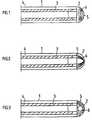
- the electrode devicecomprises an electrode cable 1, on the distal end of which an electrode head is attached.
- the electrode head 2consists of an electrically conductive material, such as titanium nitride, and is connected to an elongate conductor 3 which extends to the proximal end of the electrode cable, not shown here.
- the electrode cable 1is also provided with an outer insulating layer 4. In this FIG it is shown that the electrode head 2 is provided with a centrally arranged round stimulation surface 5.
- the remaining surface layer of the electrode headis provided with an insulating material 6, which is called "diamond-like carbon" and is shortened as a DLC.
- This materialis high-resistance, extremely hard and also extremely biocompatible.
- the materialcan be applied so thinly that the difference in the distance between the stimulation surface and the heart tissue or the insulating layer and the heart tissue does not influence the threshold value in the case of an applied electrode device. In other words, the shape of the electrode head is not affected by the coating.
- the electrode head 2is divided into triangular sections 5, 6, in which every second section 6 is covered with a layer of the insulating material mentioned, the remaining sections 5 serving as stimulation surfaces.
- the electrode head 2is provided with a number of round stimulation surfaces 5, which are isolated from one another by means of a layer 6 made of a DLC material.
- the electrode head of the electrode device according to the inventionis not limited to the described and shown embodiments.
- the essential thingis that the invention provides an electrode head that is simple and cheap to manufacture, on which an insulating material with the aforementioned good properties can be distributed in a simple manner over the surface of the electrode head in such a way that a desired pattern with a desired number Stimulation surfaces, the sizes and shapes of which can be varied, are obtained.
Landscapes
- Health & Medical Sciences (AREA)
- Heart & Thoracic Surgery (AREA)
- Vascular Medicine (AREA)
- Cardiology (AREA)
- Engineering & Computer Science (AREA)
- Biomedical Technology (AREA)
- Nuclear Medicine, Radiotherapy & Molecular Imaging (AREA)
- Radiology & Medical Imaging (AREA)
- Life Sciences & Earth Sciences (AREA)
- Animal Behavior & Ethology (AREA)
- General Health & Medical Sciences (AREA)
- Public Health (AREA)
- Veterinary Medicine (AREA)
- Electrotherapy Devices (AREA)
Description
Translated fromGermanDie Erfindung bezieht sich auf eine Elektrodenvorrichtung zur intrakorporalen Stimulation des Körpergewebes, insbesondere zur intrakardialen Stimulation von Herzgewebe mit einem Elektrodenkabel, das mindestens einen langgestreckten isolierten Leiter und einen Elektrodenkopf, der am distalen Ende des Elektrodenkabels angebracht ist, umfasst,wobei die Oberfläche des Elektrodenkopfes teils aus Isoliermaterial und teils aus einem mit dem Leiter verbundenen elektrisch leitenden Material, das mindestens eine Stimulationsoberfläche bildet, besteht.The invention relates to an electrode device for intracorporeal stimulation of body tissue, in particular for intracardiac stimulation of heart tissue with an electrode cable, which comprises at least one elongated insulated conductor and an electrode head which is attached to the distal end of the electrode cable, the surface of the electrode head being partially consists of insulating material and partly of an electrically conductive material connected to the conductor, which forms at least one stimulation surface.
Eine solche Elektrodenvorrichtung ist durch die US-PS 3 911 928 bekannt. Der Kopf der Elektrodenvorrichtung ist mit einer Anzahl verhältnismässig kleiner, leitender Oberflächen versehen, damit der Schwellenwert und damit auch der Energieverbrauch auf diese Weise gesenkt wird. Der Elektrodenkopf besteht aus einem Kern aus einem elektrisch leitenden Material mit vom Kern herausragenden, vorgeformten Teilen, wobei der Zwischenraum zwischen diesen herausragenden Teilen mit einem elektrisch isolierenden Material ausgefüllt ist. Die vorgeformten herausragenden Teile können streifenförmig, dornenförmig odgl. ausgebildet sein, damit am Elektrodenkopf eine streifenförmige oder punktförmige Verteilung der Stimulationsoberfläche erhalten wird. Ein solcher Aufbau des Elektrodenkopfes ist herstellungsmässig kompliziert und dadurch teuer.Such an electrode device is known from US Pat. No. 3,911,928. The head of the electrode device is provided with a number of relatively small, conductive surfaces so that the threshold value and thus also the energy consumption is reduced in this way. The electrode head consists of a core made of an electrically conductive material with preformed parts protruding from the core, the space between these protruding parts being filled with an electrically insulating material. The preformed protruding parts can be strip-shaped, thorn-shaped or the like. be designed so that a strip-shaped or punctiform distribution of the stimulation surface is obtained on the electrode head. Such a construction of the electrode head is complicated in terms of production and therefore expensive.
Bei einer Elektrodenvorrichtung der eingangs genannten Art, die einen Elektrodenkopf, der eine Anzahl kleine Stimulationsoberflächen hat, aufweist, ist es erforderlich, dass diese Oberflächen einen guten Kontakt zum stimulierbaren Herzgewebe haben. Daher ist es notwendig, dass das Isoliermaterial, das einen grossen Teil der Oberfläche des Elektrodenkopfes bildet, extrem biokompatibel ist, damit das Risiko einer fibrösen Gewebebildung um den Elektrodenkopf reduziert wird. Die Gefahr fibrösen Gewebes ist, dass es so dick um den Elektrodenkopf wachsen kann, dass es zu einer Vergrösserung des Abstandes zwischen den Stimulationsoberflächen und dem stimulierbaren Herzgewebe kommt.In the case of an electrode device of the type mentioned at the beginning, which has an electrode head which has a number of small stimulation surfaces, it is necessary that these surfaces have good contact with the stimulable heart tissue. It is therefore necessary that the insulating material, which forms a large part of the surface of the electrode head, is extremely biocompatible, so that the risk of fibrous tissue formation around the electrode head is reduced. The danger of fibrous tissue is that it can grow so thick around the electrode head that there is an increase in the distance between the stimulation surfaces and the stimulable heart tissue.
Der Erfindung liegt die Aufgabe zugrunde, eine Elektrodenvorrichtung der eingangs genannten Art mit einem Elektrodenkopf zu schaffen, der im Aufbau einfach und daher verhältnismässig billig ist und bei dem gewährleistet ist, dass dessen Stimulationsoberflächen bei einer implantierten Elektrodenvorrichtung einen sehr guten Kontakt mit dem zu stimulierenden Herzgewebe hat. Ausserdem soll das Isoliermaterial extrem biokompatibel sein.The invention has for its object to provide an electrode device of the type mentioned with an electrode head which is simple in construction and therefore relatively cheap and which ensures that the stimulation surfaces of an implanted electrode device make very good contact with the heart tissue to be stimulated Has. In addition, the insulation material should be extremely biocompatible.
Diese Aufgabe ist erfindungsgemäss dadurch gelöst, dass mindestens die gesamte Oberflächenschicht des Elektrodenkopfes aus einem leitenden Material besteht und dass diese Oberflächenschicht die gewünschte Form des Elektrodenkopfes definiert und dass das leitende Material teilweise mit einer Schicht aus einem hochohmigen Isoliermaterial bedeckt ist, die derart dünn ist, dass der Unterschied des Abstandes zwischen der Stimulationsoberfläche und dem Herzgewebe bzw. der Isolierschicht und dem Herzgewebe bei einer applizierten Elektrodenvorrichtung den Schwellenwert nicht beeinflusst. Dadurch, daß die Oberflächenschicht des Elektrodenkopfes mit einem dünnen hochohmigen Isoliermaterial bedeckt wird, können die Herstellungskosten bezüglich dieses Teils der Elektrodenvorrichtung erheblich reduziert werden. Auch die Form und die Grösse der Stimulationsoberflächen können durch die Erfindung in einer einfachen und gewünschten Weise variiert werden. In einem Artikel in der Fachzeitschrift "Journal of Surgical Research", Band 11, Nr. 3, Mars 1971, Seiten 105 - 110 mit dem Titel "Decreasing electrode size and increasing efficiency of Cardiac stimulation" von Furman, Parker und Escher ist das Verhältnis zwischen der Grösse der Stimulationsoberfläche und dem Schwellenwert beschrieben. In einem hier gezeigten Diagramm kann abgelesen werden, dass der Schwellenwert proportional zu einer kleiner werdenden Grösse der Stimulationsoberfläche gesenkt wird. In dem gleichen Artikel ist ein Elektrodenkopf für eine Herzschrittmacherelektrode von einem sog. Kugelkopf-Modell abgebildet und beschrieben. Der Kugelkopf, der als Stimulationsoberfläche dient, ist derart klein, dass diese Elektrode zu den kleinflächigen Elektroden gezählt wird. Der Nachteil einer solchen Form und Grösse des Elektrodenkopfes ist, dass er leicht die Herzwand beschädigen und im schlimmsten Fall penetrieren kann.This object is achieved according to the invention in that at least the entire surface layer of the electrode head consists of a conductive material and that this surface layer defines the desired shape of the electrode head and that the conductive material is partially covered with a layer of a high-resistance insulating material which is so thin, that the difference in the distance between the stimulation surface and the heart tissue or the insulating layer and the heart tissue in an applied electrode device does not influence the threshold value. By covering the surface layer of the electrode head with a thin, high-resistance insulating material, the manufacturing costs for this part of the electrode device can be considerably reduced. The shape and size of the stimulation surfaces can also be varied in a simple and desired manner by the invention. In an article in the journal "Journal of Surgical Research", Volume 11, No. 3, Mars 1971, pages 105-110 with the title "Decreasing electrode size and increasing efficiency of Cardiac stimulation" by Furman, Parker and Escher describes the relationship between the size of the stimulation surface and the threshold. It can be seen in a diagram shown here that the threshold value is reduced in proportion to a smaller size of the stimulation surface. In the same article, an electrode head for a pacemaker electrode is depicted and described by a so-called spherical head model. The spherical head, which serves as the stimulation surface, is so small that this electrode is counted among the small-area electrodes. The disadvantage of such a shape and size of the electrode head is that it can easily damage the heart wall and, in the worst case, penetrate it.
Eine Vergrösserung des Abstandes zwischen der Stimulationsoberfläche und einem stimulierbaren Herzgewebe mit 0,1 mm kann den Schwellenwert um etwa 0,5 V erhöhen. In diesem Zusammenhang kann erwähnt werden, dass der Durchschnitt des Schwellenwertes einer Stimulationsoberfläche mit einer Flächengrösse von 3,5 mm2 etwa 0,6 V ist.Je kleiner die Stimulationsfläche, um so wesentlicher ist es, dass der Abstand klein ist. Daher wird nach der Erfindung vorgeschlagen, dass die Stärke des Isoliermateriales zwischen 0,1 und 10 µm liegt. Eine derartig dünne Isoliermaterialschicht hat weder Einfluss auf den Schwellenwert noch auf die Form des Elektrodenkopfes.Increasing the distance between the stimulation surface and a stimulable heart tissue by 0.1 mm can increase the threshold value by approximately 0.5 V. In this connection it can be mentioned that the average of the threshold value of a stimulation surface with an area size of 3.5 mm2 is approximately 0.6 V. The smaller the stimulation area, the more important it is that the distance is small. It is therefore proposed according to the invention that the thickness of the insulating material is between 0.1 and 10 microns. Such a thin layer of insulating material has no influence on the threshold value or on the shape of the electrode head.
In einer vorteilhaften Ausbildung der Erfindung wird vorgeschlagen, dass das Isoliermaterial aus einem extremen harten Kohlenstoff, auch "diamond like carbon" mit der Verkürzung DLC genannt, besteht. Dieses Material kann sehr dünn aufgetragen werden und trotzdem als ein hochohmiges Isoliermaterial dienen. Das Isoliermaterial ist ferner extrem biokompatibel. Dadurch, dass das Material auch extrem hart ist, wird die isolierende Oberfläche am Elektrodenkopf sehr abreibfest. In der Fachzeitschrift "Diamond and related materials" von 1992 ist auf Seite 727 bis 773 ein Artikel über das Material DLC publiziert. Das Isoliermaterial DLC kann u.a. mit Hilfe von Laser aufgelegt werden. In der schwedischen Fachzeitschrift "Ytform" Nr. 6, Seite 19 von 1992 ist beschrieben, dass mit einer chemischen Reaktion, die durch einen dünnen Laserstrahl ausgelöst wird, dünne Flächenbelege in komplizierten Mustern geschaffen werden können, wobei bestimmte Teile, die als Stimulationsoberflächen vorgesehen sind, nicht mit der DLC-Schicht belegt werden. Eine andere Art, einen Elektrodenkopf des genannten Typs zu erhalten ist, die gesamte Oberfläche des Kopfes mit einer DLC-Schicht zu belegen und danach die Stimulationsoberflächen mittels Fotoätzung nach Wunsch freizulegen. Der Hersteller kann also mittels Laser oder Fotoätzung entscheiden, wie der DLC-Belag über die Elektrodenfläche verteilt werden soll. Dadurch wird ein gewünschtes Muster erhalten.In an advantageous embodiment of the invention it is proposed that the insulating material consist of an extremely hard carbon, also called "diamond like carbon" with the shortening DLC. This material can be applied very thinly and still serve as a high-resistance insulating material. The insulating material is also extremely biocompatible. The fact that the material is also extremely hard makes the insulating surface on the electrode head very abrasion-resistant. In the trade journal "Diamond and related materials" from 1992 there is an article on pages 727 to 773 about published the material DLC. The insulating material DLC can be applied using a laser, among other things. The Swedish trade magazine "Ytform" No. 6, page 19 of 1992 describes that a chemical reaction, which is triggered by a thin laser beam, can be used to create thin surface coverings in complicated patterns, certain parts being provided as stimulation surfaces not be covered with the DLC layer. Another way of obtaining an electrode head of the type mentioned is to cover the entire surface of the head with a DLC layer and then to expose the stimulation surfaces by photoetching as desired. The manufacturer can use laser or photo etching to decide how the DLC coating should be distributed over the electrode surface. A desired pattern is thereby obtained.
Die Erfindung ist nachfolgend anhand eines in den Zeichnungen dargestellten Ausführungsbeispiels näher erläutert. Es zeigen:
- FIG 1 bis 3
- Seitenansichten des distalen Endes einer Elek trodenvorrichtung nach der Erfindung mit ver schiedenen Ausführungsformen der Stimulations- bzw. Isolieroberflächen am Elektrodenkopf.
- 1 to 3
- Side views of the distal end of an electrode device according to the invention with different embodiments of the stimulation or insulating surfaces on the electrode head.
In der FIG 1 ist das distale Ende einer Elektrodenvorrichtung zur intrakardialen Stimulation von Herzgewebe eines Patienten abgebildet. Die Elektrodenvorrichtung umfasst ein Elektrodenkabel 1, an dessem distalen Ende ein Elektrodenkopf angebracht ist. Der Elektrodenkopf 2 besteht aus einem elektrisch leitenden Material, wie z.B. Titannitrid und ist an einem langgestreckten Leiter 3 angeschlossen, der sich bis zu dem hier nicht gezeigten proximalen Ende des Elektrodenkabels erstreckt. Das Elektrodenkabel 1 ist auch mit einer äusseren Isolierschicht 4 versehen. In dieser FIG ist gezeigt, dass der Elektrodenkopf 2 mit einer zentrisch angeordneten runden Stimulationsoberfläche 5 versehen ist. Die übrige Oberflächenschicht des Elektrodenkopfes ist mit einem Isoliermaterial 6, das "diamond like carbon" genannt und als DLC verkürzt wird, versehen. Dieses Material ist hochohmig, extrem hart und ausserdem extrem biokompatibel. Das Material kann derart dünn aufgelegt werden, dass der Unterschied des Abstandes zwischen der Stimulationsoberfläche und dem Herzgewebe bzw. der Isolierschicht und dem Herzgewebe bei einer applizierten Elektrodenvorrichtung den Schwellenwert nicht beeinflusst. Mit anderen Worten wird die Form des Elektrodenkopfes durch den Belag nicht beeinflusst.1 shows the distal end of an electrode device for intracardial stimulation of a patient's heart tissue. The electrode device comprises an
In der FIG 2 ist der Elektrodenkopf 2 in dreieckförmige Abschnitte 5, 6 aufgeteilt, bei denen jeder zweite Abschnitt 6 mit einer Schicht des erwähnten Isoliermaterials bedeckt ist, wobei die übrigen Abschnitte 5 als Stimulationsoberflächen dienen.2, the
In der FIG 3 ist der Elektrodenkopf 2 mit einer Anzahl runder Stimulationsoberflächen 5, die mittels einer Schicht 6 aus einem DLC-Material voneinander isoliert sind, versehen.In FIG. 3, the
Der Elektrodenkopf der Elektrodenvorrichtung nach der Erfindung ist nicht auf die beschriebenen und gezeigten Ausführungsformen beschränkt. Das Wesentliche ist, dass durch die Erfindung ein in der Herstellung einfacher und billiger Elektrodenkopf gegeben ist, an dem ein Isoliermaterial mit den erwähnten guten Eigenschaften in einer einfachen Weise derart über die Oberfläche des Elektrodenkopfes verteilt werden kann, dass ein gewünschtes Muster mit einer gewünschten Anzahl Stimulationsoberflächen, deren Grösseren und Formen variiert werden können, erhalten wird.The electrode head of the electrode device according to the invention is not limited to the described and shown embodiments. The essential thing is that the invention provides an electrode head that is simple and cheap to manufacture, on which an insulating material with the aforementioned good properties can be distributed in a simple manner over the surface of the electrode head in such a way that a desired pattern with a desired number Stimulation surfaces, the sizes and shapes of which can be varied, are obtained.
Claims (3)
- Electrode device for inter-body stimulation of the body tissue, in particular for intracardial stimulation of heart tissue, with an electrode cable (1) which comprises at least one extended insulated conductor (3) and an electrode head (2) which is fitted to the distal end of the electrode cable (1), whereby the surface of the electrode head (2) consists in part of insulating material (6) and in part of an electroconductive material connected to the conductor, which material forms at least one stimulation surface (5), characterized in that at least the entire surface layer of the electrode head (2) consists of a conductive material and in that this surface layer defines the desired form of the electrode head and in that the conductive material is partially covered with a layer of a high-resistance insulating material (6) which is of such a thinness that the difference between the spacing between the stimulation surface and the heart tissue, and the insulating layer (6) and the heart tissue with an applied electrode device does not influence the threshold value.
- Electrode device according to claim 1, characterized in that the thickness of the insulating material (6) is between 0.1 and 10 µm.
- Electrode device according to claim 1 or 2, characterized in that the insulating material (6) consists of an extremely hard carbon, also called "diamond-like carbon".
Applications Claiming Priority (2)
| Application Number | Priority Date | Filing Date | Title |
|---|---|---|---|
| SE9300469 | 1993-02-12 | ||
| SE9300469ASE9300469D0 (en) | 1993-02-12 | 1993-02-12 | The electrode device |
Publications (3)
| Publication Number | Publication Date |
|---|---|
| EP0620024A1 EP0620024A1 (en) | 1994-10-19 |
| EP0620024B1true EP0620024B1 (en) | 1997-03-12 |
| EP0620024B2 EP0620024B2 (en) | 2009-11-25 |
Family
ID=20388875
Family Applications (1)
| Application Number | Title | Priority Date | Filing Date |
|---|---|---|---|
| EP94100796AExpired - LifetimeEP0620024B2 (en) | 1993-02-12 | 1994-01-20 | Electrode device |
Country Status (5)
| Country | Link |
|---|---|
| US (1) | US5405373A (en) |
| EP (1) | EP0620024B2 (en) |
| JP (1) | JPH06246006A (en) |
| DE (1) | DE59401995D1 (en) |
| SE (1) | SE9300469D0 (en) |
Cited By (10)
| Publication number | Priority date | Publication date | Assignee | Title |
|---|---|---|---|---|
| US5913887A (en) | 1996-03-01 | 1999-06-22 | Cardiac Pacemakers, Inc. | Device for the transvenous cardioversion of atrial fibrillation or atrial flutter including three coil electrodes |
| US6085119A (en) | 1998-07-22 | 2000-07-04 | Cardiac Pacemakers, Inc. | Single pass endocardial lead for multi-site atrial pacing |
| US6152954A (en) | 1998-07-22 | 2000-11-28 | Cardiac Pacemakers, Inc. | Single pass lead having retractable, actively attached electrode for pacing and sensing |
| US6212434B1 (en) | 1998-07-22 | 2001-04-03 | Cardiac Pacemakers, Inc. | Single pass lead system |
| US6321122B1 (en) | 1998-07-22 | 2001-11-20 | Cardiac Pacemakers, Inc. | Single pass defibrillation/pacing lead with passively attached electrode for pacing and sensing |
| US6463334B1 (en) | 1998-11-02 | 2002-10-08 | Cardiac Pacemakers, Inc. | Extendable and retractable lead |
| US7421299B2 (en) | 2002-12-13 | 2008-09-02 | W.C. Heraeus Gmbh & Co. Kg | Stimulation electrode and methods of making and using same |
| US7643885B2 (en) | 2004-12-23 | 2010-01-05 | Siemens Aktiengesellschaft | Intravenous pacemaker electrode |
| US7774934B2 (en) | 1998-07-22 | 2010-08-17 | Cardiac Pacemakers, Inc. | Method for making a terminal connector |
| US8078287B2 (en) | 2003-12-23 | 2011-12-13 | Cardiac Pacemakers, Inc. | His bundle mapping, pacing, and injection lead |
Families Citing this family (31)
| Publication number | Priority date | Publication date | Assignee | Title |
|---|---|---|---|---|
| US5496362A (en)* | 1992-11-24 | 1996-03-05 | Cardiac Pacemakers, Inc. | Implantable conformal coil patch electrode with multiple conductive elements for cardioversion and defibrillation |
| DE4440386A1 (en)* | 1994-11-11 | 1996-05-15 | Pacesetter Ab | Electrodes for medical applications |
| US5755759A (en)* | 1996-03-14 | 1998-05-26 | Eic Laboratories, Inc. | Biomedical device with a protective overlayer |
| US5871529A (en)* | 1997-01-16 | 1999-02-16 | Cardiac Pacemakers, Inc. | Electrode for high impedance heart stimulation |
| US6494881B1 (en)* | 1997-09-30 | 2002-12-17 | Scimed Life Systems, Inc. | Apparatus and method for electrode-surgical tissue removal having a selectively insulated electrode |
| US6501994B1 (en)* | 1997-12-24 | 2002-12-31 | Cardiac Pacemakers, Inc. | High impedance electrode tip |
| US6134478A (en)* | 1998-06-05 | 2000-10-17 | Intermedics Inc. | Method for making cardiac leads with zone insulated electrodes |
| US6240320B1 (en)* | 1998-06-05 | 2001-05-29 | Intermedics Inc. | Cardiac lead with zone insulated electrodes |
| US6546292B1 (en)* | 1998-11-04 | 2003-04-08 | Gore Enterprise Holdings, Inc. | High impedance, low polarization cardiac electrode |
| NL1012896C2 (en)* | 1999-08-24 | 2001-03-06 | Dereks Patent Bv | Visor assembly. |
| US6363286B1 (en) | 1999-09-24 | 2002-03-26 | Cardiac Pacemakers, Inc. | High impedance electrode assembly |
| US6587733B1 (en)* | 2000-02-08 | 2003-07-01 | Medtronic, Inc. | Percutaneous surgical lead body with directed stimulation |
| EP1341579B1 (en)* | 2000-12-07 | 2006-11-29 | Medtronic, Inc. | Directional brain stimulation and recording leads |
| US6728575B2 (en)* | 2001-11-30 | 2004-04-27 | St. Jude Medical Ab | Method and circuit for detecting cardiac rhythm abnormalities using a differential signal from a lead with a multi-electrode tip |
| US6997926B2 (en)* | 2002-02-04 | 2006-02-14 | Boston Scientific Scimed, Inc. | Resistance heated tissue morcellation |
| US8017178B2 (en)* | 2003-12-16 | 2011-09-13 | Cardiac Pacemakers, Inc. | Coatings for implantable electrodes |
| US8423139B2 (en) | 2004-12-20 | 2013-04-16 | Cardiac Pacemakers, Inc. | Methods, devices and systems for cardiac rhythm management using an electrode arrangement |
| US8326423B2 (en) | 2004-12-20 | 2012-12-04 | Cardiac Pacemakers, Inc. | Devices and methods for steering electrical stimulation in cardiac rhythm management |
| US8010191B2 (en) | 2004-12-20 | 2011-08-30 | Cardiac Pacemakers, Inc. | Systems, devices and methods for monitoring efficiency of pacing |
| US8290586B2 (en) | 2004-12-20 | 2012-10-16 | Cardiac Pacemakers, Inc. | Methods, devices and systems for single-chamber pacing using a dual-chamber pacing device |
| US8010192B2 (en) | 2004-12-20 | 2011-08-30 | Cardiac Pacemakers, Inc. | Endocardial pacing relating to conduction abnormalities |
| US8005544B2 (en) | 2004-12-20 | 2011-08-23 | Cardiac Pacemakers, Inc. | Endocardial pacing devices and methods useful for resynchronization and defibrillation |
| AR047851A1 (en) | 2004-12-20 | 2006-03-01 | Giniger Alberto German | A NEW MARCAPASOS THAT RESTORES OR PRESERVES THE PHYSIOLOGICAL ELECTRIC DRIVING OF THE HEART AND A METHOD OF APPLICATION |
| WO2006083881A1 (en)* | 2005-01-31 | 2006-08-10 | Medtronic, Inc. | Method of manufacturing a medical lead |
| US7711437B1 (en) | 2006-11-22 | 2010-05-04 | Pacesetter, Inc. | Lead fixation device |
| US7979140B2 (en)* | 2006-12-12 | 2011-07-12 | Alfred E. Mann Foundation For Scientific Research | Segmented electrode |
| WO2010071849A2 (en) | 2008-12-19 | 2010-06-24 | Action Medical, Inc. | Devices, methods, and systems including cardiac pacing |
| JP5090389B2 (en)* | 2009-02-26 | 2012-12-05 | オーエスジー株式会社 | DLC coated lure |
| GB2479587A (en)* | 2010-04-16 | 2011-10-19 | Diamond Detectors Ltd | Diamond microelectrode |
| WO2011139691A1 (en) | 2010-04-27 | 2011-11-10 | Cardiac Pacemakers, Inc. | His-bundle capture verification and monitoring |
| CN107106065A (en) | 2015-02-13 | 2017-08-29 | 心脏起搏器股份公司 | Implanted electrode |
Family Cites Families (9)
| Publication number | Priority date | Publication date | Assignee | Title |
|---|---|---|---|---|
| DE2319054C3 (en)* | 1973-04-14 | 1980-03-06 | Hans Dr.Med. Stockholm Lagergren | Electrode arrangement |
| DE3166638D1 (en)* | 1980-12-23 | 1984-11-15 | Kontron Ag | Implantable electrode |
| US4995382A (en)* | 1981-02-13 | 1991-02-26 | Smith And Nephew Associated Companies Limited | Wound dressing, manufacture and use |
| US4955382A (en)* | 1984-03-06 | 1990-09-11 | Ep Technologies | Apparatus and method for recording monophasic action potentials from an in vivo heart |
| US4649937A (en)* | 1985-01-28 | 1987-03-17 | Cordis Corporation | Etched grooved electrode for pacing lead and method for making same |
| US4848352A (en)* | 1987-02-13 | 1989-07-18 | Telectronics, N.V. | Method for cardiac pacing and sensing using combination of electrodes |
| US5097843A (en)* | 1990-04-10 | 1992-03-24 | Siemens-Pacesetter, Inc. | Porous electrode for a pacemaker |
| US5181526A (en)* | 1990-04-20 | 1993-01-26 | Tanaka Kikinzoku Kogyo K.K. | Electrode for human heart pacemaker |
| US5179962A (en)* | 1991-06-20 | 1993-01-19 | Possis Medical, Inc. | Cardiac lead with retractible fixators |
- 1993
- 1993-02-12SESE9300469Apatent/SE9300469D0/enunknown
- 1994
- 1994-01-20DEDE59401995Tpatent/DE59401995D1/ennot_activeExpired - Lifetime
- 1994-01-20EPEP94100796Apatent/EP0620024B2/ennot_activeExpired - Lifetime
- 1994-02-07USUS08/192,711patent/US5405373A/ennot_activeExpired - Lifetime
- 1994-02-10JPJP6016587Apatent/JPH06246006A/enactivePending
Cited By (20)
| Publication number | Priority date | Publication date | Assignee | Title |
|---|---|---|---|---|
| US6741894B2 (en) | 1996-03-01 | 2004-05-25 | Cardiac Pacemakers, Inc. | Device for the transvenous cardioversion of atrial fibrillation or atrial flutter |
| US6041256A (en) | 1996-03-01 | 2000-03-21 | Cardiac Pacemakers, Inc. | Device for the transvenous cardioversion of atrial fibrillation or atrial flutter |
| US7366574B2 (en) | 1996-03-01 | 2008-04-29 | Cardiac Pacemakers, Inc. | Device for the transvenous cardioversion of atrial fibrillation or atrial flutter |
| US5913887A (en) | 1996-03-01 | 1999-06-22 | Cardiac Pacemakers, Inc. | Device for the transvenous cardioversion of atrial fibrillation or atrial flutter including three coil electrodes |
| US6915169B2 (en) | 1998-07-22 | 2005-07-05 | Cardiac Pacemakers, Inc. | Extendable and retractable lead having a snap-fit terminal connector |
| US6085119A (en) | 1998-07-22 | 2000-07-04 | Cardiac Pacemakers, Inc. | Single pass endocardial lead for multi-site atrial pacing |
| US6345204B1 (en) | 1998-07-22 | 2002-02-05 | Cardiac Pacemakers, Inc. | Single pass lead having retractable, actively attached electrode for pacing and sensing |
| US8285398B2 (en) | 1998-07-22 | 2012-10-09 | Cardiac Pacemakers, Inc. | Lead with terminal connector assembly |
| US6505082B1 (en) | 1998-07-22 | 2003-01-07 | Cardiac Pacemakers, Inc. | Single pass lead system |
| US6212434B1 (en) | 1998-07-22 | 2001-04-03 | Cardiac Pacemakers, Inc. | Single pass lead system |
| US6152954A (en) | 1998-07-22 | 2000-11-28 | Cardiac Pacemakers, Inc. | Single pass lead having retractable, actively attached electrode for pacing and sensing |
| US6321122B1 (en) | 1998-07-22 | 2001-11-20 | Cardiac Pacemakers, Inc. | Single pass defibrillation/pacing lead with passively attached electrode for pacing and sensing |
| US7392095B2 (en) | 1998-07-22 | 2008-06-24 | Cardiac Pacemakers, Inc. | Extendable and retractable lead having a snap-fit terminal connector |
| US8209035B2 (en) | 1998-07-22 | 2012-06-26 | Cardiac Pacemakers, Inc. | Extendable and retractable lead having a snap-fit terminal connector |
| US7774934B2 (en) | 1998-07-22 | 2010-08-17 | Cardiac Pacemakers, Inc. | Method for making a terminal connector |
| US6463334B1 (en) | 1998-11-02 | 2002-10-08 | Cardiac Pacemakers, Inc. | Extendable and retractable lead |
| US7871662B2 (en) | 2002-12-13 | 2011-01-18 | W.C. Heraeus Gmbh | Method for producing a stimulation electrode |
| US7421299B2 (en) | 2002-12-13 | 2008-09-02 | W.C. Heraeus Gmbh & Co. Kg | Stimulation electrode and methods of making and using same |
| US8078287B2 (en) | 2003-12-23 | 2011-12-13 | Cardiac Pacemakers, Inc. | His bundle mapping, pacing, and injection lead |
| US7643885B2 (en) | 2004-12-23 | 2010-01-05 | Siemens Aktiengesellschaft | Intravenous pacemaker electrode |
Also Published As
| Publication number | Publication date |
|---|---|
| JPH06246006A (en) | 1994-09-06 |
| EP0620024B2 (en) | 2009-11-25 |
| SE9300469D0 (en) | 1993-02-12 |
| EP0620024A1 (en) | 1994-10-19 |
| DE59401995D1 (en) | 1997-04-17 |
| US5405373A (en) | 1995-04-11 |
Similar Documents
| Publication | Publication Date | Title |
|---|---|---|
| EP0620024B1 (en) | Electrode device | |
| DE69329919T2 (en) | Flexible electrode head for an implantable device lead | |
| DE69821928T2 (en) | INTRA-CARDIAL DEFIBRILLING SYSTEM | |
| DE2652195C3 (en) | Pacemaker electrode arrangement | |
| DE69514126T2 (en) | Electrode permanently implanted by sewing to elute medication | |
| DE69517728T2 (en) | Electrode arrangement with a variable distance between the electrodes | |
| DE69321690T2 (en) | Electrode system for a defibrillation device | |
| DE69323374T2 (en) | Foldable cushion electrode for cardiac defibrillation with an area without conductors, which serves as a hinge | |
| DE68919833T2 (en) | Intervening lead for irritation and defibrillation. | |
| DE68923555T2 (en) | TRANSVENOUSLY INSERTABLE ELECTRODE CABLE FOR HEART DEFIBRILLATION. | |
| DE69314383T2 (en) | Electrode for highly effective tissue irritation and for the reception of signals | |
| EP0563614B1 (en) | Defibrillation electrode | |
| DE60111222T2 (en) | ELECTRICALLY INSULATED CABLE WITH MULTIPLE LADDERS | |
| DE69503467T2 (en) | TEMPORARY MEDICAL ELECTRODE | |
| DE69321030T3 (en) | Device for stimulating the heart | |
| DE69430417T2 (en) | electrode system | |
| DE2643956C2 (en) | Electrode system for the rhythm correction of a dysfunctional heart | |
| EP0843574B1 (en) | Cuff electrode | |
| DE69716940T2 (en) | ELECTRO-PHYSIOLOGICAL CATHETER WITH ELECTRODE IN THE FORM OF A BULL EYE | |
| DE69833361T2 (en) | Medical electrical supply | |
| DE69318659T2 (en) | Electrode system for pacemakers | |
| DE69326404T2 (en) | Multipole electrode lead | |
| DE3048805A1 (en) | IMPLANTABLE LINE | |
| DE2613086B2 (en) | Endocardial electrode | |
| DE3152726C2 (en) | Implantable electrode assembly for a cardioverter |
Legal Events
| Date | Code | Title | Description |
|---|---|---|---|
| PUAI | Public reference made under article 153(3) epc to a published international application that has entered the european phase | Free format text:ORIGINAL CODE: 0009012 | |
| AK | Designated contracting states | Kind code of ref document:A1 Designated state(s):DE FR GB IT NL | |
| 17P | Request for examination filed | Effective date:19941104 | |
| RAP1 | Party data changed (applicant data changed or rights of an application transferred) | Owner name:PACESETTER AB | |
| GRAG | Despatch of communication of intention to grant | Free format text:ORIGINAL CODE: EPIDOS AGRA | |
| 17Q | First examination report despatched | Effective date:19960325 | |
| GRAH | Despatch of communication of intention to grant a patent | Free format text:ORIGINAL CODE: EPIDOS IGRA | |
| GRAH | Despatch of communication of intention to grant a patent | Free format text:ORIGINAL CODE: EPIDOS IGRA | |
| GRAA | (expected) grant | Free format text:ORIGINAL CODE: 0009210 | |
| AK | Designated contracting states | Kind code of ref document:B1 Designated state(s):DE FR GB IT NL | |
| REF | Corresponds to: | Ref document number:59401995 Country of ref document:DE Date of ref document:19970417 | |
| ET | Fr: translation filed | ||
| ITF | It: translation for a ep patent filed | ||
| PGFP | Annual fee paid to national office [announced via postgrant information from national office to epo] | Ref country code:GB Payment date:19971125 Year of fee payment:5 | |
| PLBQ | Unpublished change to opponent data | Free format text:ORIGINAL CODE: EPIDOS OPPO | |
| PLBI | Opposition filed | Free format text:ORIGINAL CODE: 0009260 | |
| PLBF | Reply of patent proprietor to notice(s) of opposition | Free format text:ORIGINAL CODE: EPIDOS OBSO | |
| 26 | Opposition filed | Opponent name:BIOTRONIK MESS- UND THERAPIEGERAETE GMBH & CO INGE Effective date:19971211 | |
| NLR1 | Nl: opposition has been filed with the epo | Opponent name:BIOTRONIK MESS- UND THERAPIEGERAETE GMBH & CO INGE | |
| PLBF | Reply of patent proprietor to notice(s) of opposition | Free format text:ORIGINAL CODE: EPIDOS OBSO | |
| PLBF | Reply of patent proprietor to notice(s) of opposition | Free format text:ORIGINAL CODE: EPIDOS OBSO | |
| PG25 | Lapsed in a contracting state [announced via postgrant information from national office to epo] | Ref country code:GB Free format text:LAPSE BECAUSE OF NON-PAYMENT OF DUE FEES Effective date:19990120 | |
| GBPC | Gb: european patent ceased through non-payment of renewal fee | Effective date:19990120 | |
| PLAV | Examination of admissibility of opposition | Free format text:ORIGINAL CODE: EPIDOS OPEX | |
| PLBQ | Unpublished change to opponent data | Free format text:ORIGINAL CODE: EPIDOS OPPO | |
| PLAB | Opposition data, opponent's data or that of the opponent's representative modified | Free format text:ORIGINAL CODE: 0009299OPPO | |
| PLBI | Opposition filed | Free format text:ORIGINAL CODE: 0009260 | |
| PGFP | Annual fee paid to national office [announced via postgrant information from national office to epo] | Ref country code:NL Payment date:20000131 Year of fee payment:7 | |
| 26 | Opposition filed | Opponent name:BIOTRONIK MESS- UND THERAPIEGERAETE GMBH & CO INGE Effective date:19971211 | |
| PLBO | Opposition rejected | Free format text:ORIGINAL CODE: EPIDOS REJO | |
| NLR1 | Nl: opposition has been filed with the epo | Opponent name:BIOTRONIK MESS- UND THERAPIEGERAETE GMBH & CO INGE | |
| APAC | Appeal dossier modified | Free format text:ORIGINAL CODE: EPIDOS NOAPO | |
| APAE | Appeal reference modified | Free format text:ORIGINAL CODE: EPIDOS REFNO | |
| RAP2 | Party data changed (patent owner data changed or rights of a patent transferred) | Owner name:ST. JUDE MEDICAL AB | |
| APAC | Appeal dossier modified | Free format text:ORIGINAL CODE: EPIDOS NOAPO | |
| NLT2 | Nl: modifications (of names), taken from the european patent patent bulletin | Owner name:ST. JUDE MEDICAL AB | |
| PG25 | Lapsed in a contracting state [announced via postgrant information from national office to epo] | Ref country code:NL Free format text:LAPSE BECAUSE OF NON-PAYMENT OF DUE FEES Effective date:20010801 | |
| NLV4 | Nl: lapsed or anulled due to non-payment of the annual fee | Effective date:20010801 | |
| PLAB | Opposition data, opponent's data or that of the opponent's representative modified | Free format text:ORIGINAL CODE: 0009299OPPO | |
| R26 | Opposition filed (corrected) | Opponent name:BIOTRONIK GMBH & CO. KG Effective date:19971211 | |
| APBU | Appeal procedure closed | Free format text:ORIGINAL CODE: EPIDOSNNOA9O | |
| PLAY | Examination report in opposition despatched + time limit | Free format text:ORIGINAL CODE: EPIDOSNORE2 | |
| PLAH | Information related to despatch of examination report in opposition + time limit modified | Free format text:ORIGINAL CODE: EPIDOSCORE2 | |
| APAH | Appeal reference modified | Free format text:ORIGINAL CODE: EPIDOSCREFNO | |
| PLBC | Reply to examination report in opposition received | Free format text:ORIGINAL CODE: EPIDOSNORE3 | |
| APBP | Date of receipt of notice of appeal recorded | Free format text:ORIGINAL CODE: EPIDOSNNOA2O | |
| APAH | Appeal reference modified | Free format text:ORIGINAL CODE: EPIDOSCREFNO | |
| APBQ | Date of receipt of statement of grounds of appeal recorded | Free format text:ORIGINAL CODE: EPIDOSNNOA3O | |
| PGFP | Annual fee paid to national office [announced via postgrant information from national office to epo] | Ref country code:IT Payment date:20070616 Year of fee payment:14 | |
| APBU | Appeal procedure closed | Free format text:ORIGINAL CODE: EPIDOSNNOA9O | |
| PG25 | Lapsed in a contracting state [announced via postgrant information from national office to epo] | Ref country code:IT Free format text:LAPSE BECAUSE OF NON-PAYMENT OF DUE FEES Effective date:20080120 | |
| PUAH | Patent maintained in amended form | Free format text:ORIGINAL CODE: 0009272 | |
| STAA | Information on the status of an ep patent application or granted ep patent | Free format text:STATUS: PATENT MAINTAINED AS AMENDED | |
| 27A | Patent maintained in amended form | Effective date:20091125 | |
| AK | Designated contracting states | Kind code of ref document:B2 Designated state(s):DE FR GB IT NL | |
| PGFP | Annual fee paid to national office [announced via postgrant information from national office to epo] | Ref country code:FR Payment date:20100223 Year of fee payment:17 | |
| PGFP | Annual fee paid to national office [announced via postgrant information from national office to epo] | Ref country code:DE Payment date:20100127 Year of fee payment:17 | |
| REG | Reference to a national code | Ref country code:FR Ref legal event code:ST Effective date:20110930 | |
| PG25 | Lapsed in a contracting state [announced via postgrant information from national office to epo] | Ref country code:FR Free format text:LAPSE BECAUSE OF NON-PAYMENT OF DUE FEES Effective date:20110131 | |
| REG | Reference to a national code | Ref country code:DE Ref legal event code:R119 Ref document number:59401995 Country of ref document:DE Effective date:20110802 | |
| PG25 | Lapsed in a contracting state [announced via postgrant information from national office to epo] | Ref country code:DE Free format text:LAPSE BECAUSE OF NON-PAYMENT OF DUE FEES Effective date:20110802 |