EP0617296B1 - Method and system for obstacle detection, installed on a automotive vehicle - Google Patents
Method and system for obstacle detection, installed on a automotive vehicleDownload PDFInfo
- Publication number
- EP0617296B1 EP0617296B1EP94400449AEP94400449AEP0617296B1EP 0617296 B1EP0617296 B1EP 0617296B1EP 94400449 AEP94400449 AEP 94400449AEP 94400449 AEP94400449 AEP 94400449AEP 0617296 B1EP0617296 B1EP 0617296B1
- Authority
- EP
- European Patent Office
- Prior art keywords
- plane
- image
- vehicle
- matrix
- sensor
- Prior art date
- Legal status (The legal status is an assumption and is not a legal conclusion. Google has not performed a legal analysis and makes no representation as to the accuracy of the status listed.)
- Expired - Lifetime
Links
Images


Classifications
- G—PHYSICS
- G01—MEASURING; TESTING
- G01S—RADIO DIRECTION-FINDING; RADIO NAVIGATION; DETERMINING DISTANCE OR VELOCITY BY USE OF RADIO WAVES; LOCATING OR PRESENCE-DETECTING BY USE OF THE REFLECTION OR RERADIATION OF RADIO WAVES; ANALOGOUS ARRANGEMENTS USING OTHER WAVES
- G01S11/00—Systems for determining distance or velocity not using reflection or reradiation
- G01S11/12—Systems for determining distance or velocity not using reflection or reradiation using electromagnetic waves other than radio waves
- G—PHYSICS
- G01—MEASURING; TESTING
- G01S—RADIO DIRECTION-FINDING; RADIO NAVIGATION; DETERMINING DISTANCE OR VELOCITY BY USE OF RADIO WAVES; LOCATING OR PRESENCE-DETECTING BY USE OF THE REFLECTION OR RERADIATION OF RADIO WAVES; ANALOGOUS ARRANGEMENTS USING OTHER WAVES
- G01S17/00—Systems using the reflection or reradiation of electromagnetic waves other than radio waves, e.g. lidar systems
- G01S17/88—Lidar systems specially adapted for specific applications
- G01S17/93—Lidar systems specially adapted for specific applications for anti-collision purposes
- G01S17/931—Lidar systems specially adapted for specific applications for anti-collision purposes of land vehicles
- B—PERFORMING OPERATIONS; TRANSPORTING
- B60—VEHICLES IN GENERAL
- B60R—VEHICLES, VEHICLE FITTINGS, OR VEHICLE PARTS, NOT OTHERWISE PROVIDED FOR
- B60R21/00—Arrangements or fittings on vehicles for protecting or preventing injuries to occupants or pedestrians in case of accidents or other traffic risks
- B60R21/01—Electrical circuits for triggering passive safety arrangements, e.g. airbags, safety belt tighteners, in case of vehicle accidents or impending vehicle accidents
- B60R21/013—Electrical circuits for triggering passive safety arrangements, e.g. airbags, safety belt tighteners, in case of vehicle accidents or impending vehicle accidents including means for detecting collisions, impending collisions or roll-over
Definitions
- the present inventionrelates to a detection device of obstacles, on board a motor vehicle.
- the object of the present inventionis a detection device of obstacles on board a motor vehicle, which provides information on the distance from the obstacle to the vehicle while being precise and reliable.
- the detection deviceis intended for detect obstacles crossing a plane P substantially parallel to the vehicle floor and passing through this vehicle, this device comprising a sensor images consisting of a lens, a matrix sensor on which is formed an image, and electronic image processing means coupled to vehicle driver information means, characterized in that the matrix sensor is located in a plane substantially perpendicular to the plane P and in the plane of symmetry of the vehicle, the objective consists of a cylindrical lens or of a portion of cylindrical lens whose axis is parallel to the plane of the matrix sensor and inclined relative to the plane of symmetry of the vehicle, this image sensor being placed in the vehicle so that its field is superimposed on the plane P, and the image processing means are arranged to define in a coordinate system linked to the plane P, the coordinates of each point of intersection of these obstacles with plane P.
- the cylindrical lensis replaced by a superimposed lenses or spherical lens portions offset relative to each other so that their optical centers are on the same axis parallel to the plane of the matrix sensor but inclined by compared to this one.
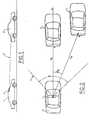
- FIG. 1This figure shows a vehicle 1 fitted with an image sensor 2 according to the invention.
- Sensor 2is fixed on the rear face of the vehicle interior mirror and is slightly tilted down.
- the field of this sensorcan be assimilated, as will be explained below, to a plane P cutting the obstacle constituted by a vehicle 3 placed in front vehicle 1.
- the sensor 2which determines an origin O, covers in the plane P, an angle ⁇ likely to cover the entire width of the road.
- the plane Phere intersects the vehicle 3 of FIG. 1, located on the same longitudinal axis as the vehicle 1, as well as a vehicle 4 located to the right of the vehicle A. More precisely, the plane P intersects the vehicles 3 and 4 along straight lines which, if these vehicles are at a certain distance from the vehicle 1, can be compared to their environment, A and B respectively.
- the device according to the inventionmakes it possible to determine the angle ⁇ and the dimension z of each point A and B in a reference frame linked to the plane P and originating from the half-line Oz formed by the intersection of the plane P with the plane of symmetry of the vehicle 1 .
- a source point Swhich could be one points A or B in Figure 2, a lens 5, a sensor matrix 6 and electronic processing means 7 (for example image scanning then image analysis numerical or direct electronic calculation) coupled with driver information means 8 for assistance with conduct of it.
- driver information means 8can be means visual, information displayed for example on a display screen integrated into the driving position and / or sound, such as an alarm or an artificial voice.
- the objective 5consists of a superposition, in a plane parallel to that of the sensor 6, therefore substantially vertical, of parallelepipedic portions of spherical lenses 5a, 5b, ..., 5i, ... 5n offset from each other to the others so that their optical centers C a , ... C i , ..., C n are aligned on an axis parallel to the plane of the matrix sensor 6 and inclined relative to the plane of symmetry of the vehicle 1.
- the source point Shas for image with respect to each of the lens portions 5a to 5n, an image point S a , S b , ... S i , ... S n .
- the optical centers C a to C nbeing aligned, the image points S a to S n are also aligned.
- the image on the sensor 6 of point Sis a line segment.
- all the other source points, intersections of obstacles with the plane Phave for image a straight line on the matrix sensor 6.
- the electronic means located in the housinginterpret these images in order to determine the coordinates ⁇ and z of each source point. These coordinates are then brought to the knowledge of the driver, in various forms, by the means 8.
- the information concerning these coordinatescan be supplemented or replaced by information concerning for example the presence or not of obstacles, the distance of these obstacles to the vehicle, the relative speed of these obstacles with respect to the vehicle.
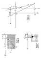
- FIG. 4similar to FIG. 3 but on which the objective consists of a parallelepipedic portion of cylindrical lens 5 ′ whose axis is parallel to the plane of the matrix sensor 6 and is inclined relative to the plane of symmetry of the vehicle 1.
- This cylindrical lensis similar, from an optical point of view, to the superposition of portions of spherical lenses in FIG. 3. Indeed, if we assume the lenses of FIG. 3 sufficiently small, by a transition to the limit, these lenses are similar to a cylindrical lens.
- the axis of the cylindrical lens 5 ′is analogous to the axis on which the optical centers C a to C n of the lens portions 5a to 5n are aligned.
- the two extreme optical centers of the lens 5 'have been identified by C 1 and C 2 .
- the image, on the sensor 6, of the source point Sis, as in FIG. 3, a straight line whose ends are the two image points S ' 1 and S' 2 .
- FIG. 5On a coordinate axis O'x, we have identified by i and j the abscissae relative to origins O ′, respectively O ′ ', of the ends of the line-image segment of the source point S, that is to say of the image points S 1 and S 2 .
- Point O ''is defined below.
- the electronic means 7include image processing algorithms (by way of nonlimiting example: contour extraction followed by a HOUGH transform) making it possible to extract from the different line segments, the line segment relating to each source point. For each line segment, we extract the equation of this segment and therefore the abscissas i and j of the points S 1 and S 2 .
- the sensor 2is shown diagrammatically in projection on a plane perpendicular to the planes of the matrix 6 and of the lens 5 ′.
- the projection in this plane of the matrix sensor 6is the axis O'x and C ' 1 and C' 2 are the projections of the optical centers C 1 and C 2 .
- C ' 1 C' 2we denote by a the distance C ' 1 C' 2 and by d the distance between the lines C ' 1 C' 2 and O'x, that is to say the distance between the lens and the matrix sensor. It was considered that point O in FIG. 2 was confused with C ' 1 .
- the inventionmakes it possible to locate all obstacles intersecting the plane P; it applies particularly well to driving where the vertical dimension is not very significant and where a substantially horizontal dimension sufficient, which allows the use of a system horizontal convergence optics such as the lens described above. It gives precise results and reliable; moreover, it only uses an image sensor.
- the inventionmakes it possible to easily solve the problem of matching, that is to say of the pairing of the extreme image points (S a and S n or S 1 and S 2 ).
- the inter-sampling created by the superposition of lenses between the extreme lenses (5a and 5n) or by the inclined cylindrical lensmakes it possible to connect these extreme image points by a line segment which it is easy to extract by means an image processing algorithm (by way of nonlimiting example: contour extraction followed by a HOUGH transform).
Landscapes
- Physics & Mathematics (AREA)
- Engineering & Computer Science (AREA)
- Electromagnetism (AREA)
- General Physics & Mathematics (AREA)
- Radar, Positioning & Navigation (AREA)
- Remote Sensing (AREA)
- Computer Networks & Wireless Communication (AREA)
- Traffic Control Systems (AREA)
- Image Processing (AREA)
Description
Translated fromFrenchLa présente invention se rapporte à un dispositif de détectiond'obstacles, embarqué sur un véhicule automobile.The present invention relates to a detection deviceof obstacles, on board a motor vehicle.
On connaít des systèmes de détection d'obstacles utilisant descapteurs d'images ou caméras, notamment de type CCD (c'est-à-dire"Charge Coupled Device", ou en français : "Dispositif à transfert decharge"). On pourra se référer par exemple au brevet allemandDE 4114304. Cependant, si une caméra permet d'obtenir une image endeux dimensions de la scène routière, elle ne donne pas directement derenseignement concernant la profondeur, c'est-à-dire la distance del'obstacle au point de prise de vue situé dans le véhicule.There are known obstacle detection systems usingimage sensors or cameras, in particular of the CCD type (i.e."Charge Coupled Device", or in French: "Device with transfer ofcharge "). We could refer for example to the German patentDE 4114304. However, if a camera makes it possible to obtain an image intwo dimensions of the road scene, it does not directly givedepth information, i.e. the distance fromthe obstacle at the point of view located in the vehicle.
Pour pallier cet inconvénient, on peut utiliser deux caméras etcalculer la profondeur par un procédé de stéréovision, mais ce procédéest difficile à mettre en oeuvre. Outre le problème d'épipolarité se pose leproblème de mise en correspondance, c'est-à-dire de l'appariement dechaque élément caractéristique de l'image de l'une des deux camérasavec l'élément correspondant de l'image de l'autre caméra. De plus, ceprocédé demande, pour être robuste, des capacités de calcul trèsimportantes et est donc mal adapté aux systèmes embarqués. Ces diversproblèmes contribuent à un manque de précision et de fiabilité de ceprocédé de stéréovision.To overcome this drawback, two cameras can be used andcalculate the depth by a stereovision method, but this methodis difficult to implement. In addition to the epipolarity problem, themapping problem, that is, the matching ofeach characteristic element of the image of one of the two cameraswith the corresponding element of the image from the other camera. In addition, thisto be robust, very computational capacities are requiredimportant and is therefore ill-suited to embedded systems. These variousproblems contribute to a lack of precision and reliability of thisstereovision process.
La présente invention a pour but un dispositif de détectiond'obstacles embarqué sur un véhicule automobile, qui renseigne sur ladistance de l'obstacle au véhicule tout en étant précis et fiable.The object of the present invention is a detection deviceof obstacles on board a motor vehicle, which provides information on thedistance from the obstacle to the vehicle while being precise and reliable.
Plus précisément; le dispositif de détection selon l'invention est destiné àdétecter les obstacles coupant un plan P sensiblement parallèle auplancher du véhicule et passant par ce véhicule, ce dispositif comportant un capteurd'images constitué d'un objectif, d'un capteur matriciel sur lequel se formeune image, et des moyens de traitement électronique de l'image couplésà des moyens d'information du conducteur du véhicule, caractérisé en ce quele capteur matriciel est situé dans un plan sensiblement perpendiculaire au plan P etau plan de symétrie du véhicule, l'objectif est constitué d'une lentille cylindriqueou d'une portion de lentille cylindrique dont l'axe est parallèle au plan du capteur matriciel et incliné par rapport au plan de symétrie du véhicule, cecapteur d'images étant placé dans le véhicule de façon que son champ sesuperpose au plan P, et les moyens de traitement de l'image sont arrangéspour définir dans unrepère lié au plan P, les coordonnées de chaque point d'intersection deces obstacles avec le plan P.More precisely; the detection device according to the invention is intended fordetect obstacles crossing a plane P substantially parallel to thevehicle floor and passing through this vehicle, this device comprising a sensorimages consisting of a lens, a matrix sensor on which is formedan image, and electronic image processing means coupledto vehicle driver information means, characterized in thatthe matrix sensor is located in a plane substantially perpendicular to the plane P andin the plane of symmetry of the vehicle, the objective consists of a cylindrical lensor of a portion of cylindrical lens whose axis is parallel to the plane of thematrix sensor and inclined relative to the plane of symmetry of the vehicle, thisimage sensor being placed in the vehicle so that its field issuperimposed on the plane P, and the image processing means are arrangedto define in acoordinate system linked to the plane P, the coordinates of each point of intersection ofthese obstacles with plane P.
Selon une variante, la lentille cylindrique est remplacée par unesuperposition de lentilles ou de portions de lentilles sphériques décaléesles unes par rapport aux autres de sorte que leurs centres optiques soientsur un même axe parallèle au plan du capteur matriciel mais incliné parrapport à celui-ci.Alternatively, the cylindrical lens is replaced by asuperimposed lenses or spherical lens portions offsetrelative to each other so that their optical centers areon the same axis parallel to the plane of the matrix sensor but inclined bycompared to this one.
Les coordonnées , z et leurs barres d'incertitude sontdéterminées par les relations suivantes :
- δ est la résolution du capteur matriciel
- d est la distance entre l'objectif et le capteurmatriciel
- a est la distance entre les projections, sur le planP, des centres optiques extrèmes de l'objectif
- i est l'abscisse de l'intersection avec la premièreligne de la matrice du capteur matriciel, du segment dedroite qui constitue l'image du point dont les coordonnéessont recherchées, ce segment étant extrait au moyen d'unalgorithme de traitement d'image.
- Δi=j-i, j étant l'abscisse de l'intersection avec ladernière ligne de la matrice du capteur matriciel, dusegment de droite qui constitue l'image du point dont lescoordonnées sont recherchées, ce segment étant extrait aumoyen d'un algorithme de traitement d'image.
- δ is the resolution of the matrix sensor
- d is the distance between the objective and the matrix sensor
- a is the distance between the projections, on the plane P, of the extreme optical centers of the objective
- i is the abscissa of the intersection with the first line of the matrix of the matrix sensor, of the line segment which constitutes the image of the point whose coordinates are sought, this segment being extracted by means of a processing algorithm d 'picture.
- Δi = ji, j being the abscissa of the intersection with the last line of the matrix of the matrix sensor, of the line segment which constitutes the image of the point whose coordinates are sought, this segment being extracted by means of a image processing algorithm.
L'invention va maintenant être décrite plus en détail,en référence à un mode de réalisation donné à titre d'exempleet représenté par les dessins annexés sur lesquels :
- la figure 1 est un schéma d'implantation du dispositifselon l'invention sur un véhicule,
- la figure 2 est un schéma de principe du dispositifselon l'invention,
- la figure 3 représente les éléments du dispositifselon l'invention,
- la figure 4 représente une variante de la figure 3,
- la figure 5 représente le capteur matriciel desfigures 3 et 4,
- la figure 6 représente schématiquement en vue dedessus le dispositif optique des figures 3 et 4,
- la figure 7 représente, en vue agrandie, un détail dela figure 5.
- FIG. 1 is a layout diagram of the device according to the invention on a vehicle,
- FIG. 2 is a block diagram of the device according to the invention,
- FIG. 3 represents the elements of the device according to the invention,
- FIG. 4 represents a variant of FIG. 3,
- FIG. 5 represents the matrix sensor of FIGS. 3 and 4,
- FIG. 6 schematically represents a top view of the optical device of FIGS. 3 and 4,
- FIG. 7 represents, in an enlarged view, a detail of FIG. 5.
Sur toutes ces figures, les éléments correspondantsportent les mêmes repères.In all these figures, the corresponding elementshave the same marks.
On se reportera tout d'abord à la figure 1. Cettefigure montre un véhicule 1 muni d'un capteur d'images 2selon l'invention. Le capteur 2 est fixé sur la face arrièredu rétroviseur intérieur du véhicule et est légèrementincliné vers le bas. Le champ de ce capteur peut êtreassimilé, comme on l'expliquera plus loin, à un plan Pcoupant l'obstacle que constitue un véhicule 3 placé devantle véhicule 1.We will first refer to Figure 1. Thisfigure shows a
Si l'on se reporte à la figure 2, on voit que lecapteur 2, qui détermine une origine O, couvre dans le planP, un angle γ susceptible de couvrir toute la largeur de laroute. Le plan P coupe ici le véhicule 3 de la figure 1,situé sur le même axe longitudinal que le véhicule 1, ainsiqu'un véhicule 4 situé à droite du véhicule A.
Plus précisément, le plan P coupe les véhicules 3 et 4 selondes segments de droite que l'on peut, si ces véhicules sontà une certaine distance du véhicule 1, assimiler à leurmilieu, respectivement A et B. Le dispositif selon l'inventionpermet de déterminer l'angle et la cote z de chaquepoint A et B dans un repère lié au plan P et ayant pourorigine la demi-droite Oz constituée par l'intersection duplan P avec le plan de symétrie du véhicule 1.If we refer to Figure 2, we see that the
More precisely, the plane P intersects the vehicles 3 and 4 along straight lines which, if these vehicles are at a certain distance from the
On se reportera maintenant à la figure 3 sur laquelleon a représenté un point source S, qui pourrait être l'undes points A ou B de la figure 2, un objectif 5, un capteurmatriciel 6 et des moyens 7 de traitement électronique (parexemple numérisation de l'image puis analyse de l'imagenumérique ou calcul électronique direct) couplés à desmoyens 8 d'information du conducteur pour l'aide à laconduite de celui-ci. Ces moyens 8 peuvent être des moyensvisuels, les informations s'affichant par exemple sur unécran de visualisation intégré au poste de conduite et/ousonores, tels qu'une alarme ou une voix artificielle.We will now refer to Figure 3 on whichwe have represented a source point S, which could be onepoints A or B in Figure 2, a lens 5, a sensormatrix 6 and electronic processing means 7 (forexample image scanning then image analysisnumerical or direct electronic calculation) coupled withdriver information means 8 for assistance withconduct of it. These means 8 can be meansvisual, information displayed for example on adisplay screen integrated into the driving position and / orsound, such as an alarm or an artificial voice.
L'objectif 5 est constitué d'une superposition, dans unplan parallèle à celui du capteur 6, donc sensiblementvertical, de portions parallélépipèdiques de lentillessphériques 5a, 5b,...,5i,...5n décalées les unes par rapportaux autres de sorte que leurs centres optiquesCa,...Ci,...,Cn soient alignés sur un axe parallèle au plandu capteur matriciel 6 et incliné par rapport au plan desymétrie du véhicule 1. Sur la figure 3, on n'a représentéque 5 portions de lentilles mais on peut en superposer parexemple une vingtaine (n=20).The objective 5 consists of a superposition, in a plane parallel to that of the sensor 6, therefore substantially vertical, of parallelepipedic portions of
Le point source S a pour image par rapport à chacunedes portions de lentilles 5a à 5n, un point-image Sa,Sb,...Si,...Sn. Les centres optiques Ca à Cn étant alignés,les points-images Sa à Sn le sont aussi. Ainsi, l'image surle capteur 6 du point S est un segment de droite. De même,tous les autres points sources, intersections d'obstaclesavec le plan P ont pour image un segment de droite sur lecapteur matriciel 6. Les moyens électroniques situés dans leboítier interprètent ces images afin de déterminer lescoordonnées et z de chaque point source. Ces coordonnéessont ensuite portées à la connaissance du conducteur, sousdiverses formes, par les moyens 8. L'information concernantces coordonnées peut être complétée ou remplacée par desinformations concernant par exemple la présence ou non d'obstacles, la distance de ces obstacles au véhicule, lavitesse relative de ces obstacles par rapport au véhicule.The source point S has for image with respect to each of the
On se reportera maintenant à la figure 4, analogue à lafigure 3 mais sur laquelle l'objectif est constitué d'uneportion parallélépipédique de lentille cylindrique 5' dontl'axe est parallèle au plan du capteur matriciel 6 et estincliné par rapport au plan de symétrie du véhicule 1. Cettelentille cylindrique est analogue, du point de vue optique,à la superposition de portions de lentilles sphériques de lafigure 3. En effet, si l'on suppose les lentilles de lafigure 3 suffisamment petites, par un passage à la limite,ces lentilles sont assimilables à une lentille cylindrique.L'axe de la lentille cylindrique 5' est analogue à l'axe surlequel sont alignés les centres optiques Ca à Cn desportions de lentilles 5a à 5n. On a repéré par C1 et C2 lesdeux centres optiques extrêmes de la lentille 5'. L'image,sur le capteur 6, du point source S est, comme sur la figure3, un segment de droite dont les extrémités sont les deuxpoints-images S'1 et S'2.We will now refer to FIG. 4, similar to FIG. 3 but on which the objective consists of a parallelepipedic portion of cylindrical lens 5 ′ whose axis is parallel to the plane of the matrix sensor 6 and is inclined relative to the plane of symmetry of the
Pour plus de simplicité, on considérera désormais quel'on se trouve dans le cas de la figure 4, la transpositiondu mode de la figure 4 à celui de la figure 3 se faisantaisément en remplaçant C1 et C2 par Ca et Cn et S1 et S2 parSa et Sn.For simplicity, we will now consider that we are in the case of Figure 4, the transposition of the mode of Figure 4 to that of Figure 3 is easily done by replacing C1 and C2 by Ca and Cn and S1 and S2 by Sa and Sn .
On se reportera maintenant à la figure 5 sur laquelleon a représenté en détail le capteur matriciel 6. Sur un axede coordonnées O'x, on a repéré par i et j les abscissesrelatives par rapport à des origines O', respectivement O'',des extrémités du segment de droite-image du point source S,c'est-à-dire des points-images S1 et S2. Le point O'' estdéfini ci-après. Les moyens électroniques 7 comportent desalgorithmes de traitement d'image (à titre d'exemple nonlimitatif : extraction de contour suivie d'une transforméede HOUGH) permettant d'extraire parmi les différents segments de droite, le segment de droite relatif à chaquepoint source. Pour chaque segment de droite, on extraitl'équation de ce segment et donc les abscisses i et j despoints S1 et S2.We will now refer to FIG. 5 in which the matrix sensor 6 has been shown in detail. On a coordinate axis O'x, we have identified by i and j the abscissae relative to origins O ′, respectively O ′ ', of the ends of the line-image segment of the source point S, that is to say of the image points S1 and S2 . Point O '' is defined below. The electronic means 7 include image processing algorithms (by way of nonlimiting example: contour extraction followed by a HOUGH transform) making it possible to extract from the different line segments, the line segment relating to each source point. For each line segment, we extract the equation of this segment and therefore the abscissas i and j of the points S1 and S2 .
Sur la figure 6, on a représenté schématiquement lecapteur 2 en projection sur un plan perpendiculaire auxplans de la matrice 6 et de la lentille 5'. La projectiondans ce plan du capteur matriciel 6 est l'axe O'x et C'1 etC'2 sont les projections des centres optiques C1 et C2. On adésigné par a la distance C'1 C'2 et par d la distance entreles droites C'1 C'2 et O'x, c'est-à-dire la distance entrela lentille et le capteur matriciel. On a considéré que lepoint O de la figure 2 était confondu avec C'1. On a désignépar δ la résolution du capteur matriciel 6, c'est-à-dire ladistance inter-pixel. On a désigné par So la projection dupoint S sur l'axe Oz, par O" la projection de C'2 sur l'axeO'x, par O"z" un axe parallèle à l'axe O'z et par S"o laprojection de S sur cet axe O"z".In FIG. 6, the
On appelle λ et r les distances respectivement à l'axeO'z et O"z" des projections sur l'axe O'x des impactslumineux que constituent les points-images S1 et S2.We call λ and r the distances respectively to the axis O'z and O "z" of the projections on the axis O'x of the light impacts that constitute the image points S1 and S2 .
En regardant notamment la figure 7, on peut écrire :
δi < λ < δ (i + 1)
δj < r < δ (j + 1)
δi <λ <δ (i + 1)
δj <r <δ (j + 1)
En considérant que l'impact lumineux a un diamètre d'1pixel, on peut écrire :


L'invention permet de localiser tous les obstaclescoupant le plan P ; elle s'applique particulièrement bien àla conduite automobile où la dimension verticale n'est pastrès significative et où une dimension sensiblement horizontalesuffit, ce qui permet l'utilisation d'un systèmeoptique à convergence horizontale tel que la lentilledécrite ci-dessus. Elle donne des résultats précis etfiables ; en outre, elle n'utilise qu'un capteur d'images.The invention makes it possible to locate all obstaclesintersecting the plane P; it applies particularly well todriving where the vertical dimension is notvery significant and where a substantially horizontal dimensionsufficient, which allows the use of a systemhorizontal convergence optics such as the lensdescribed above. It gives precise results andreliable; moreover, it only uses an image sensor.
L'invention permet de résoudre aisément le problème demise en correspondance, c'est-à-dire de l'appariement despoints images extrêmes (Sa et Sn ou S1 et S2). En effet,l'interéchantillonnage créé par la superposition de lentillesentre les lentilles extrêmes (5a et 5n) ou par lalentille cylindrique inclinée, permet de relier ces pointsimages extrêmes par un segment de droite qu'il est aiséd'extraire au moyen d'un algorithme de traitement d'image (àtitre d'exemple non limitatif : extraction de contour suivied'une transformée de HOUGH).The invention makes it possible to easily solve the problem of matching, that is to say of the pairing of the extreme image points (Sa and Sn or S1 and S2 ). Indeed, the inter-sampling created by the superposition of lenses between the extreme lenses (5a and 5n) or by the inclined cylindrical lens, makes it possible to connect these extreme image points by a line segment which it is easy to extract by means an image processing algorithm (by way of nonlimiting example: contour extraction followed by a HOUGH transform).
Claims (7)
- Obstacle-detection device on board a motor vehicle, intended to detectobstacles intersecting a plane P substantially parallel to the floor of the vehicleand passing through this vehicle, this device comprising an image sensorconstituted by an objective, a matrix-type sensor on which an image is formed,and means for electronically processing the image, coupled with means forinforming the driver of the vehicle, characterised in that
the matrix-type sensor is located in a plane substantially perpendicular to theplane P and to the plane of symmetry of the vehicle, the objective is constitutedby a cylindrical lens or a portion of cylindrical lens, the axis of which is parallelto the plane of the matrix-type sensor and inclined with respect to the plane ofsymmetry of the vehicle, this image sensor being placed inside the vehicle sothat its field is superimposed on the plane P, and the image-processing meansare arranged so as to define, within a reference point connected to the planeP, the co-ordinates of each point of intersection of said obstacles with theplane P. - Device according to Claim 1,
characterised in that the image sensor is fixed to the rear face of the internalrear-view mirror of the vehicle and is slightly inclined downwards. - Device according to Claim 1,
characterised in that the image sensor is fixed to the vehicle at the level of theprojectors and is slightly inclined upwards. - Device according to any one of the preceding claims,
characterised in that the cylindrical lens is replaced by a superimposition oflenses or portions of spherical lenses offset from one another so that theiroptical centres are on the same axis parallel to the plane of the matrix-typesensor but inclined with respect thereto. - Device according to any one of the preceding claims,
characterised in that the electronic processing means determine the co-ordinates and z of each point of intersection of the obstacles with the planeP, the origin of the co-ordinates being located level with the sensor, by thefollowing relationships: where
where δ is the resolution of the matrix-type sensord is the distance between the objective and the matrix-type sensora is the distance between the projections, on the plane P, of the extremeoptical centres of the objectivei is the abscissa of the intersection with the first line of the matrix of thematrix-type sensor of the segment of straight line that constitutes theimage of the point, the co-ordinates of which are sought, this segmentbeing extracted by means of an image-processing algorithmΔi = j - i, j being the abscissa of the intersection with the last line of thematrix of the matrix-type sensor, of the segment of straight line thatconstitutes the image of the point, the co-ordinates for which are sought,this segment being extracted by means of an image-processing algorithm.
 - Device according to any one of the preceding claims,
characterised in that the means for informing the driver are visual, andcomprise for example a display screen integrated into the driving station. - Device according to any one of the preceding claims,
characterised in that the means for informing the driver are sound-based.


Applications Claiming Priority (2)
| Application Number | Priority Date | Filing Date | Title |
|---|---|---|---|
| FR9303253 | 1993-03-22 | ||
| FR9303253AFR2703173B1 (en) | 1993-03-22 | 1993-03-22 | Method and device for obstacle detection, on board a motor vehicle. |
Publications (2)
| Publication Number | Publication Date |
|---|---|
| EP0617296A1 EP0617296A1 (en) | 1994-09-28 |
| EP0617296B1true EP0617296B1 (en) | 1998-04-22 |
Family
ID=9445197
Family Applications (1)
| Application Number | Title | Priority Date | Filing Date |
|---|---|---|---|
| EP94400449AExpired - LifetimeEP0617296B1 (en) | 1993-03-22 | 1994-03-03 | Method and system for obstacle detection, installed on a automotive vehicle |
Country Status (3)
| Country | Link |
|---|---|
| EP (1) | EP0617296B1 (en) |
| DE (1) | DE69409702T2 (en) |
| FR (1) | FR2703173B1 (en) |
Cited By (6)
| Publication number | Priority date | Publication date | Assignee | Title |
|---|---|---|---|---|
| US8818042B2 (en) | 2004-04-15 | 2014-08-26 | Magna Electronics Inc. | Driver assistance system for vehicle |
| US8842176B2 (en) | 1996-05-22 | 2014-09-23 | Donnelly Corporation | Automatic vehicle exterior light control |
| US8917169B2 (en) | 1993-02-26 | 2014-12-23 | Magna Electronics Inc. | Vehicular vision system |
| US8993951B2 (en) | 1996-03-25 | 2015-03-31 | Magna Electronics Inc. | Driver assistance system for a vehicle |
| US9171217B2 (en) | 2002-05-03 | 2015-10-27 | Magna Electronics Inc. | Vision system for vehicle |
| US9436880B2 (en) | 1999-08-12 | 2016-09-06 | Magna Electronics Inc. | Vehicle vision system |
Families Citing this family (4)
| Publication number | Priority date | Publication date | Assignee | Title |
|---|---|---|---|---|
| DE10210301A1 (en)* | 2002-03-08 | 2003-09-18 | Valeo Schalter & Sensoren Gmbh | Method and system for detecting objects in the vicinity of a vehicle |
| WO2008024639A2 (en) | 2006-08-11 | 2008-02-28 | Donnelly Corporation | Automatic headlamp control system |
| CN103522970B (en)* | 2013-05-31 | 2016-04-27 | 深圳Tcl工业研究院有限公司 | Based on vehicle driving safety method of inspection and the system of machine vision |
| EP3724027B1 (en)* | 2017-12-14 | 2021-05-26 | Lumileds LLC | Illuminant for vehicle headlight with automatic beam mode selection |
Family Cites Families (5)
| Publication number | Priority date | Publication date | Assignee | Title |
|---|---|---|---|---|
| JPS59203975A (en)* | 1983-05-06 | 1984-11-19 | Nissan Motor Co Ltd | Vehicle optical radar device |
| FR2576126B1 (en)* | 1985-01-16 | 1988-06-17 | Reinaud Guy | OPTICAL MOBILE DETECTION AND PROTECTION DEVICE |
| DE8717494U1 (en)* | 1987-09-15 | 1989-02-09 | Kolbatz, Klaus-Peter, 1000 Berlin | Parking aid for motor vehicles |
| DE4114304C1 (en)* | 1991-05-02 | 1992-04-30 | Messerschmitt-Boelkow-Blohm Gmbh, 8012 Ottobrunn, De | Area surveillance camera - has detector surfaces separated from imaging areas and in form of parallel strips of optoelectronic devices |
| DE4123056A1 (en)* | 1991-07-12 | 1993-01-14 | Bayerische Motoren Werke Ag | DISTANCE MEASURING DEVICE FOR MOTOR VEHICLES |
- 1993
- 1993-03-22FRFR9303253Apatent/FR2703173B1/ennot_activeExpired - Fee Related
- 1994
- 1994-03-03DEDE69409702Tpatent/DE69409702T2/ennot_activeExpired - Fee Related
- 1994-03-03EPEP94400449Apatent/EP0617296B1/ennot_activeExpired - Lifetime
Cited By (10)
| Publication number | Priority date | Publication date | Assignee | Title |
|---|---|---|---|---|
| US8917169B2 (en) | 1993-02-26 | 2014-12-23 | Magna Electronics Inc. | Vehicular vision system |
| US8993951B2 (en) | 1996-03-25 | 2015-03-31 | Magna Electronics Inc. | Driver assistance system for a vehicle |
| US8842176B2 (en) | 1996-05-22 | 2014-09-23 | Donnelly Corporation | Automatic vehicle exterior light control |
| US9436880B2 (en) | 1999-08-12 | 2016-09-06 | Magna Electronics Inc. | Vehicle vision system |
| US9171217B2 (en) | 2002-05-03 | 2015-10-27 | Magna Electronics Inc. | Vision system for vehicle |
| US9555803B2 (en) | 2002-05-03 | 2017-01-31 | Magna Electronics Inc. | Driver assistance system for vehicle |
| US8818042B2 (en) | 2004-04-15 | 2014-08-26 | Magna Electronics Inc. | Driver assistance system for vehicle |
| US9008369B2 (en) | 2004-04-15 | 2015-04-14 | Magna Electronics Inc. | Vision system for vehicle |
| US9191634B2 (en) | 2004-04-15 | 2015-11-17 | Magna Electronics Inc. | Vision system for vehicle |
| US9428192B2 (en) | 2004-04-15 | 2016-08-30 | Magna Electronics Inc. | Vision system for vehicle |
Also Published As
| Publication number | Publication date |
|---|---|
| DE69409702D1 (en) | 1998-05-28 |
| FR2703173B1 (en) | 1995-04-28 |
| DE69409702T2 (en) | 1998-11-12 |
| EP0617296A1 (en) | 1994-09-28 |
| FR2703173A1 (en) | 1994-09-30 |
Similar Documents
| Publication | Publication Date | Title |
|---|---|---|
| US11270134B2 (en) | Method for estimating distance to an object via a vehicular vision system | |
| KR102365501B1 (en) | Method and apparatus for calibrating the extrinsic parameter of an image sensor | |
| CA2275957C (en) | Method for calibrating the initial position and the orientation of one or several mobile cameras | |
| EP0617296B1 (en) | Method and system for obstacle detection, installed on a automotive vehicle | |
| EP1288072A2 (en) | Driver assistance device taking into account the overhang of other vehicles | |
| FR2899332A1 (en) | VISIBILITY FIELD MEASUREMENT DEVICE FOR VEHICLE AND DRIVING ASSISTANCE SYSTEM FOR VEHICLE | |
| FR2864311A1 (en) | Display system for vehicle e.g. automobile, has extraction unit extracting position on image of scene from red light element of recognized object, and windshield having display zone in which display image is superposed on scene | |
| FR2952599A1 (en) | DRIVER ASSISTANCE SYSTEM OF A MOTOR VEHICLE | |
| FR3078045A1 (en) | DEVICE AND METHOD FOR AIDING THE DRIVING OF A MOTOR VEHICLE | |
| FR3125160A3 (en) | Monitoring and alarm system for vehicles | |
| WO2010133785A1 (en) | Method and device for extending a visibility area | |
| FR2902381A1 (en) | Motor vehicle driving assisting method, involves merging image captured by image formation device of night vision system and synthesis image, and displaying merged image on internal display of night vision system | |
| EP3860881B1 (en) | Rear facing lane detection overlay | |
| EP3740810A1 (en) | Head-up display for motor vehicle and assisted-driving system including such a display | |
| EP4148657A1 (en) | Method for generating a final image of the environment of a motor vehicle | |
| EP3682320B1 (en) | Method for displaying the surroundings of a motor vehicle on a screen, and motor vehicle in which such a method is implemented | |
| EP4165601A1 (en) | Method for calibrating a camera and associated device | |
| EP2193047B1 (en) | Assistance device for exiting a hidden lane | |
| FR3080702A1 (en) | ESTIMATION OF DISTANCE SEPARATING A MOTOR VEHICLE FROM OBJECTS DETECTED BY PROCESSING IMAGES CAPTURED FROM THE MOTOR VEHICLE | |
| EP4564296A1 (en) | Method for determining the angular position of a trailer with respect to a towing vehicle | |
| EP2490071A1 (en) | Video monitoring device | |
| WO2017216465A1 (en) | Method and device for processing images acquired by a camera of a motor vehicle | |
| FR3143132A1 (en) | Method for generating an image document | |
| FR3093968A1 (en) | Vehicle rear view system comprising a plurality of cameras and a computer | |
| FR2790721A1 (en) | AID FOR VISION AIDING THE VEHICLE |
Legal Events
| Date | Code | Title | Description |
|---|---|---|---|
| PUAI | Public reference made under article 153(3) epc to a published international application that has entered the european phase | Free format text:ORIGINAL CODE: 0009012 | |
| AK | Designated contracting states | Kind code of ref document:A1 Designated state(s):DE GB IT | |
| 17P | Request for examination filed | Effective date:19941010 | |
| 17Q | First examination report despatched | Effective date:19961014 | |
| GRAG | Despatch of communication of intention to grant | Free format text:ORIGINAL CODE: EPIDOS AGRA | |
| GRAG | Despatch of communication of intention to grant | Free format text:ORIGINAL CODE: EPIDOS AGRA | |
| GRAH | Despatch of communication of intention to grant a patent | Free format text:ORIGINAL CODE: EPIDOS IGRA | |
| GRAH | Despatch of communication of intention to grant a patent | Free format text:ORIGINAL CODE: EPIDOS IGRA | |
| GRAA | (expected) grant | Free format text:ORIGINAL CODE: 0009210 | |
| AK | Designated contracting states | Kind code of ref document:B1 Designated state(s):DE GB IT | |
| GBT | Gb: translation of ep patent filed (gb section 77(6)(a)/1977) | Effective date:19980423 | |
| REF | Corresponds to: | Ref document number:69409702 Country of ref document:DE Date of ref document:19980528 | |
| ITF | It: translation for a ep patent filed | ||
| PLBE | No opposition filed within time limit | Free format text:ORIGINAL CODE: 0009261 | |
| STAA | Information on the status of an ep patent application or granted ep patent | Free format text:STATUS: NO OPPOSITION FILED WITHIN TIME LIMIT | |
| 26N | No opposition filed | ||
| REG | Reference to a national code | Ref country code:GB Ref legal event code:IF02 | |
| PGFP | Annual fee paid to national office [announced via postgrant information from national office to epo] | Ref country code:IT Payment date:20060331 Year of fee payment:13 | |
| PGFP | Annual fee paid to national office [announced via postgrant information from national office to epo] | Ref country code:GB Payment date:20070226 Year of fee payment:14 | |
| PGFP | Annual fee paid to national office [announced via postgrant information from national office to epo] | Ref country code:DE Payment date:20070307 Year of fee payment:14 | |
| GBPC | Gb: european patent ceased through non-payment of renewal fee | Effective date:20080303 | |
| PG25 | Lapsed in a contracting state [announced via postgrant information from national office to epo] | Ref country code:DE Free format text:LAPSE BECAUSE OF NON-PAYMENT OF DUE FEES Effective date:20081001 | |
| PG25 | Lapsed in a contracting state [announced via postgrant information from national office to epo] | Ref country code:GB Free format text:LAPSE BECAUSE OF NON-PAYMENT OF DUE FEES Effective date:20080303 | |
| PG25 | Lapsed in a contracting state [announced via postgrant information from national office to epo] | Ref country code:IT Free format text:LAPSE BECAUSE OF NON-PAYMENT OF DUE FEES Effective date:20070303 |