EP0616304A1 - Article surveillance element - Google Patents
Article surveillance elementDownload PDFInfo
- Publication number
- EP0616304A1 EP0616304A1EP19930119744EP93119744AEP0616304A1EP 0616304 A1EP0616304 A1EP 0616304A1EP 19930119744EP19930119744EP 19930119744EP 93119744 AEP93119744 AEP 93119744AEP 0616304 A1EP0616304 A1EP 0616304A1
- Authority
- EP
- European Patent Office
- Prior art keywords
- securing element
- article
- carrier body
- element according
- article securing
- Prior art date
- Legal status (The legal status is an assumption and is not a legal conclusion. Google has not performed a legal analysis and makes no representation as to the accuracy of the status listed.)
- Withdrawn
Links
- 239000002184metalSubstances0.000claimsabstractdescription28
- 229910052751metalInorganic materials0.000claimsabstractdescription28
- 239000000696magnetic materialSubstances0.000claimsabstractdescription6
- 238000004804windingMethods0.000claimsdescription17
- 239000004753textileSubstances0.000description3
- 230000001960triggered effectEffects0.000description3
- 230000000694effectsEffects0.000description2
- 239000007787solidSubstances0.000description2
- 229910001030Iron–nickel alloyInorganic materials0.000description1
- 239000000853adhesiveSubstances0.000description1
- 230000001070adhesive effectEffects0.000description1
- 238000013475authorizationMethods0.000description1
- -1for exampleSubstances0.000description1
- 238000004519manufacturing processMethods0.000description1
- 229910000859α-FeInorganic materials0.000description1
Images


Classifications
- G—PHYSICS
- G08—SIGNALLING
- G08B—SIGNALLING OR CALLING SYSTEMS; ORDER TELEGRAPHS; ALARM SYSTEMS
- G08B13/00—Burglar, theft or intruder alarms
- G08B13/22—Electrical actuation
- G08B13/24—Electrical actuation by interference with electromagnetic field distribution
- G08B13/2402—Electronic Article Surveillance [EAS], i.e. systems using tags for detecting removal of a tagged item from a secure area, e.g. tags for detecting shoplifting
- G08B13/2405—Electronic Article Surveillance [EAS], i.e. systems using tags for detecting removal of a tagged item from a secure area, e.g. tags for detecting shoplifting characterised by the tag technology used
- G08B13/2408—Electronic Article Surveillance [EAS], i.e. systems using tags for detecting removal of a tagged item from a secure area, e.g. tags for detecting shoplifting characterised by the tag technology used using ferromagnetic tags
- G—PHYSICS
- G08—SIGNALLING
- G08B—SIGNALLING OR CALLING SYSTEMS; ORDER TELEGRAPHS; ALARM SYSTEMS
- G08B13/00—Burglar, theft or intruder alarms
- G08B13/22—Electrical actuation
- G08B13/24—Electrical actuation by interference with electromagnetic field distribution
- G08B13/2402—Electronic Article Surveillance [EAS], i.e. systems using tags for detecting removal of a tagged item from a secure area, e.g. tags for detecting shoplifting
- G08B13/2428—Tag details
- G08B13/2434—Tag housing and attachment details
- G—PHYSICS
- G08—SIGNALLING
- G08B—SIGNALLING OR CALLING SYSTEMS; ORDER TELEGRAPHS; ALARM SYSTEMS
- G08B13/00—Burglar, theft or intruder alarms
- G08B13/22—Electrical actuation
- G08B13/24—Electrical actuation by interference with electromagnetic field distribution
- G08B13/2402—Electronic Article Surveillance [EAS], i.e. systems using tags for detecting removal of a tagged item from a secure area, e.g. tags for detecting shoplifting
- G08B13/2428—Tag details
- G08B13/2437—Tag layered structure, processes for making layered tags
- G08B13/2442—Tag materials and material properties thereof, e.g. magnetic material details
- Y—GENERAL TAGGING OF NEW TECHNOLOGICAL DEVELOPMENTS; GENERAL TAGGING OF CROSS-SECTIONAL TECHNOLOGIES SPANNING OVER SEVERAL SECTIONS OF THE IPC; TECHNICAL SUBJECTS COVERED BY FORMER USPC CROSS-REFERENCE ART COLLECTIONS [XRACs] AND DIGESTS
- Y10—TECHNICAL SUBJECTS COVERED BY FORMER USPC
- Y10T—TECHNICAL SUBJECTS COVERED BY FORMER US CLASSIFICATION
- Y10T70/00—Locks
- Y10T70/50—Special application
- Y10T70/5004—For antitheft signaling device on protected article
Definitions
- the inventionrelates to an article security element which has at least one soft magnetic metal strip.
- Article security elements of the type mentioned at the outsetare known, for example, from EP-PS 0 123 557.
- the strength of the response field emitted by the security labeldepends on the direction of the security label in relation to the query field. Did he Strips of soft magnetic metal in the same direction as the interrogation field, so that the magnetic axis of the strip is in the direction of the interrogation field, the entire strip is remagnetized with the frequency of the interrogation field and can therefore emit an electromagnetic response field, which is designed as a receiver coil Magnetic field sensor is detectable. If the strip and thus also its magnetic preferred direction is at right angles to the interrogation field, this field is not able to re-magnetize the strip so that the strip does not emit a detectable response field and the stolen article is not detected by the receiver coil.
- the soft magnetic metal stripis wound in the form of a helix on an elongated, columnar support body made of non-magnetic material with a pitch angle ⁇ , which has a value between 30 ° and 60 °. It is thereby achieved that a part of the metal strip assumes an angle with each position of the article securing element with respect to the query field which is less than or equal to 60 °. In experiments, this angle has emerged as the angle of a metal strip with respect to an interrogation field at which the metal strip is remagnetized and emits a response field that can be detected with a high probability by a magnetic field sensor. A response field that can be detected with certainty is emitted by the metal strip when the pitch angle ⁇ is between 40 ° and 50 ° and has a value of 45 °, for example.
- a carrier bodywhich is designed as a cylinder, as a cylindrical hollow body or as a tube, enables simple and efficient production of the article security element according to the invention using a type of lathe in which the cylindrical body can be clamped and wound.
- a carrier body for the soft magnetic metal stripwhich is cuboid, can be produced in a simple and inexpensive manner by cutting it off from an elongated strip of non-magnetic material with sufficient thickness, for example by sawing it off.
- the article security element according to the inventionemits a strong and certainly easily detectable response field if the metal strip winding has one turn or if it consists of two half turns which are wound in opposite directions and helically on the carrier body.
- the carrier bodyis designed as a hollow body and has in its interior a locking device for a needle for fastening the article security element to articles to be secured against theft.
- the article security elementis very easy to secure against theft To fasten textiles.
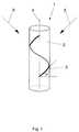
- the article security element 1 shown in FIG. 1consists of a cylindrical carrier body 2 made of a non-magnetic material, such as, for example, plastic, which can be designed as a solid body, as a hollow body or as a tube.
- the exemplary embodiments of the carrier body shown in FIGS. 1 to 5are designed as solid bodies.
- the article securing element 1is oriented such that a query field acts on the element 1 in the direction of the arrow 5, the angle between the beginning or the end of the metal strip winding 3 and the field 5 is almost 0 °. If a query field acts in the direction of arrow 6 on the article securing element 1, the middle part of the metal strip winding 3 shown in broken lines in FIG. 1 has an angle of almost 0 ° with respect to the field 6.
- This angleis of particular importance, because tests have shown that a straight strip of soft magnetic metal, which is at an angle of more than 60 ° with the connecting line between a transmitter coil and a receiver coil of an article surveillance system, does not trigger a theft alarm if it is connected to a high-frequency electromagnetic interrogation field is irradiated, whereas an alarm is most likely to be triggered if this angle is less than 60 °. In addition, has show that such an alarm is triggered with absolute certainty when this angle has a value between 40 ° and 50 °, for example. 45 °.
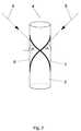
- the metal stripas shown in FIG. 2, is designed as a winding with two half turns 7 and 8, which are wound onto the carrier body 2 in opposite directions, but also helically, with a pitch angle of 45 °. If the half turns 7 and 8 touch or cross, they form an angle of 90 ° with one another.
- both windings 7 and 8assume an angle of 45 ° with respect to an electromagnetic interrogation field that is in the direction of the axis of symmetry 4 or perpendicular thereto, so that both windings 7, 8 react actively to such a field and trigger an alarm.
- a field in the direction of arrow 5only acts on the winding 8 and a field in the direction of arrow 6 only on the winding 7 such that the metal strips are remagnetized by the interrogation field and trigger theft alarm.
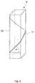
- Fig. 3shows an embodiment of an article security element 9 with a cuboid carrier body 10, which can be produced by cutting off corresponding pieces from an endless belt made of plastic with a sufficient thickness, i.e. sawing them off.
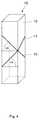
- the embodiments 12 and 13differ in that the turns 14 and 15 intersect in the embodiment 12 on one edge of the carrier body 10 and in the embodiment 13 on its front surface.
- FIG. 6shows an article securing element which consists of a tubular carrier body 16, in the interior of which a locking device for a needle 17 with a button-shaped needle head 27 is arranged.
- a cylindrical body 18 with a conical cavity 19is firmly inserted in the interior of the carrier body 16 and has a first round opening 20 for the needle 17 and a second round opening 21 on the side opposite the first opening 20 for a tubular holding body 22, which is fixedly connected to a magnet 23 mounted movably in the carrier body 16 and whose function consists in holding balls 24 and 25 and by means of the force exerted by the spring 26 on the magnet 23 into the conical taper of the conical Press cavity 19.
- a needle inserted into the opening 20presses the balls 24 and 25 and thus also the magnet 23 downward against the force of the spring 26 via the holding body 22.
- the needle 17penetrates into the interior of the holding body 22.
- the magnet 23 movably mounted in the carrier body 16 and thus also the holding body 22are pulled downward, so that the balls 24 and 25 no longer exert a clamping effect on the needle 17.
- the needle 17can now be removed from the locking device as long as the unlocking magnet acts on the movably mounted magnet 23.
Landscapes
- Physics & Mathematics (AREA)
- Engineering & Computer Science (AREA)
- Automation & Control Theory (AREA)
- Computer Security & Cryptography (AREA)
- Electromagnetism (AREA)
- General Physics & Mathematics (AREA)
- Burglar Alarm Systems (AREA)
Abstract
Description
Translated fromGermanDie Erfindung bezieht sich auf ein Artikelsicherungselement, das mindestens einen weichmagnetischen Metallstreifen aufweist.The invention relates to an article security element which has at least one soft magnetic metal strip.
Artikelsicherungselemente der eingangs erwähnten Art sind bspw. aus der EP-PS 0 123 557 bekannt. Darin ist ein aus mehreren Schichten bestehendes Sicherheitsetikett beschrieben, bei dem auf einer bandförmigen Trägerschicht ein Streifen aus einem weichmagnetischen Metall aufgeklebt ist. Die Trägerschicht und der Streifen sind von einer ebenfalls bandförmigen Deckschicht überklebt. Auf diese Weise ergibt sich ein längliches Sicherheitsetikett, das auf gegen Diebstahl zu sichernde Artikel, wie bspw. Textilien, befestigt wird. Wird ein derart gesicherter Artikel unbefugt entwendet und durch ein Sicherheitstor getragen, das sowohl eine Sendespule zum Abstrahlen eines hochfrequenten elektromagnetischen Abfragefeldes als auch eine Empfängerspule aufweist, die das vom Sicherheitsetikett als Reaktion auf das Abfragefeld abgestrahlte Antwortfeld erfaßt, wird Diebstahlalarm ausgelöst.Article security elements of the type mentioned at the outset are known, for example, from EP-PS 0 123 557. This describes a security label consisting of several layers, in which a strip of a soft magnetic metal is glued to a band-shaped carrier layer. The carrier layer and the strip are covered with a tape-like cover layer. This results in an elongated security label that is attached to items to be secured against theft, such as textiles. If an article secured in this way is stolen without authorization and carried through a security gate which has both a transmitter coil for emitting a high-frequency electromagnetic interrogation field and a receiver coil which detects the response field emitted by the security label in response to the interrogation field, theft alarm is triggered.
Die Stärke des vom Sicherheitsetikett abgestrahlten Antwortfeldes ist hierbei abhängig von der Richtung des Sicherheitsetikettes gegenüber dem Abfragefeld. Hat der Streifen aus weichmagnetischem Metall dieselbe Richtung, wie das Abfragefeld, so daß auch die magnetische Achse des Streifens in Richtung des Abfragefeldes liegt, wird der gesamte Streifen mit der Frequenz des Abfragefeldes ummagnetisiert und kann deshalb seinerseits ein elektromagnetisches Antwortfeld abstrahlen, das von einem als Empfängerspule ausgebildeten Magnetfeldsensor erfaßbar ist. Liegt der Streifen und damit auch dessen magnetische Vorzugsrichtung im rechten Winkel zu dem Abfragefeld, ist dieses Feld nicht in der Lage, den Streifen umzumagnetisieren, so daß der Streifen kein erfaßbares Antwortfeld abstrahlt und der gestohlene Artikel von der Empfängerspule nicht erfaßt wird.The strength of the response field emitted by the security label depends on the direction of the security label in relation to the query field. Did he Strips of soft magnetic metal in the same direction as the interrogation field, so that the magnetic axis of the strip is in the direction of the interrogation field, the entire strip is remagnetized with the frequency of the interrogation field and can therefore emit an electromagnetic response field, which is designed as a receiver coil Magnetic field sensor is detectable. If the strip and thus also its magnetic preferred direction is at right angles to the interrogation field, this field is not able to re-magnetize the strip so that the strip does not emit a detectable response field and the stolen article is not detected by the receiver coil.
Aufgabe der vorliegenden Erfindung ist es somit, ein Artikelsicherungselement zu schaffen, das unabhängig von seiner Richtung gegenüber einem von einer Sendespule abgestrahlten Abfragefeld ein Antwortfeld erzeugt, das von einer Empfängerspule sicher erfaßbar ist.It is therefore an object of the present invention to provide an article security element which, regardless of its direction, generates a response field with respect to a query field emitted by a transmitter coil, which can be reliably detected by a receiver coil.
Diese Augabe wird gemäß der Erfindung dadurch gelöst, daß der weichmagnetische Metallstreifen in Form einer Schraubenlinie auf einen länglichen, säulenförmigen Trägerkörper aus nichtmagnetischem Material mit einem Steigungswinkel α aufgewickelt ist, der einen Wert zwischen 30° und 60° aufweist. Hierdurch wird erreicht, daß ein Teil des Metallstreifens bei jeder Lage des Artikelsicherungselementes gegenüber dem Abfragefeld einen Winkel einnimmt, der kleiner oder gleich 60° ist. Dieser Winkel hat sich bei Versuchen als derjenige Winkel eines Metallstreifens gegenüber einem Abfragefeld ergeben hat, bei dem der Metallstreifen ummagnetisert wird und ein von einem Magnetfeldsensor mit großer Wahrscheinlichkeit erfaßbares Antwortfeld abstrahlt. Ein mit Sicherheit gut erfaßbares Antwortfeld wird vom Metallstreifen dann abgestrahlt, wenn der Steigungswinkel α zwischen 40° und 50°liegt und bspw. einen Wert von 45° hat.This claim is achieved according to the invention in that the soft magnetic metal strip is wound in the form of a helix on an elongated, columnar support body made of non-magnetic material with a pitch angle α, which has a value between 30 ° and 60 °. It is thereby achieved that a part of the metal strip assumes an angle with each position of the article securing element with respect to the query field which is less than or equal to 60 °. In experiments, this angle has emerged as the angle of a metal strip with respect to an interrogation field at which the metal strip is remagnetized and emits a response field that can be detected with a high probability by a magnetic field sensor. A response field that can be detected with certainty is emitted by the metal strip when the pitch angle α is between 40 ° and 50 ° and has a value of 45 °, for example.
Ein Trägerkörper, der als Zylinder, als zylindrischer Hohlkörper oder als Rohr ausgebildet ist, ermöglicht eine einfache und rationelle Herstellung des erfindungsgemäßen Artikelsicherungselementes unter Verwendung einer Art Drehbank, in die der zylindrische Körper eingespannt und bewickelt werden kann.A carrier body, which is designed as a cylinder, as a cylindrical hollow body or as a tube, enables simple and efficient production of the article security element according to the invention using a type of lathe in which the cylindrical body can be clamped and wound.
Ein Trägerkörper für den weichmagnetischen Metallstreifen, der quaderförmig ausgebildet ist, ist auf einfache und preisgünstige Weise dadurch herstellbar, daß er von einem länglichen Streifen aus nichtmagnetischem Material mit aureichender Dicke abgetrennt, bspw. abgesägt wird.A carrier body for the soft magnetic metal strip, which is cuboid, can be produced in a simple and inexpensive manner by cutting it off from an elongated strip of non-magnetic material with sufficient thickness, for example by sawing it off.
Experimente haben ergeben, daß das erfindungsgemäße Artikelsicherungselement ein starkes und mit Sicherheit gut erfaßbares Antwortfeld abstrahlt, wenn der Metallstreifenwickel eine Windung aufweist oder wenn er aus zwei halben Windungen besteht, die auf den Trägerkörper gegensinnig und schraubenlinienförmig aufgewickelt sind.Experiments have shown that the article security element according to the invention emits a strong and certainly easily detectable response field if the metal strip winding has one turn or if it consists of two half turns which are wound in opposite directions and helically on the carrier body.
Ein insb. zur Sicherung von Textilien gegen Diebstahl gut verwendbares Artikelsicherungselement ergibt sich, wenn der Trägerkörper als Hohlkörper ausgebildet ist und in seinem Innenraum eine Verriegelungsvorrichtung für eine Nadel zur Befestigung des Artikelsicherungselementes an gegen Diebstahl zu sichernde Artikel aufweist. Mit Hilfe der Nadel ist das Artikelsicherungselement sehr leicht an gegen Diebstahl zu sichernde Textilien zu befestigen.An article security element which can be used particularly well to secure textiles against theft is obtained if the carrier body is designed as a hollow body and has in its interior a locking device for a needle for fastening the article security element to articles to be secured against theft. With the help of the needle, the article security element is very easy to secure against theft To fasten textiles.
Einige Ausführungsbeispiele der Erfindung werden im folgenden anhand der Zeichnungen näher erläutert. Es zeigen
- Fig. 1 ein Artikelsicherungselement mit einem zylinderförmigen Trägerkörper, auf den eine Windung eines weichmagnetischer Metallstreifens schraubenlinienförmig aufgewickelt ist,
- Fig. 2 ein Artikelsicherungselement gemäß Fig. 1, auf den der Metallstreifen als ein aus zwei halben Windungen bestehender Wickel aufgebracht ist,
- Fig. 3 ein Artikelsicherungselement mit einem quaderförmigen Trägerkörper und einer Windung eines weichmagnetischen Metallstreifens,
- Fig. 4 und 5 Artikelsicherungselemente gemäß Fig. 3 mit aus zwei halben Windungen bestehenden Metallstreifenwickeln, die auf quaderförmigen Trägerkörpern aufgebracht sind und
- Fig. 6 eine in einem rohrförmigen Trägerkörper untergebrachte Verriegelungsvorrichtung.
- 1 is an article security element with a cylindrical carrier body, on which a turn of a soft magnetic metal strip is wound helically,
- 2 shows an article security element according to FIG. 1, on which the metal strip is applied as a winding consisting of two half turns,
- 3 shows an article security element with a cuboid carrier body and a turn of a soft magnetic metal strip,
- 4 and 5 article security elements according to FIG. 3 with two half-turns of metal strip windings, which are applied to cuboid carrier bodies and
- Fig. 6 is a locking device housed in a tubular support body.
Das in Fig. 1 dargestellte Artikelsicherungselement 1 besteht aus einem zylinderförmigen Trägerkörper 2 aus einem nichtmagnetischen Material, wie bspw. aus Kunststoff, der als Vollkörper, als Hohlkörper oder als Rohr ausgebildet sein kann. Die in den Fig. 1 bis 5 dargestellten Ausführungsbeispiele der Trägerkörpers sind als Vollkörper ausgebildet. Ein weichmagnetischer Metallstreifen 3, der bspw. aus Ferrit oder aus einer Nickel-Eisenlegierung besteht, ist auf den Trägerkörper 2 schraubenlinienförmig aufgewickelt und über eine Klebeverbindung auf dem Trägerkörper 2 fixiert.The
Der Streifenwickel besteht aus einer Windung und weist im vorliegenden Ausführungsbeispiel gegenüber der Horizontalen einen Steigungswinkel von α=45° auf. Hierdurch wird erreicht, daß unabhängig von der Richtung, mit der ein hochfrequentes elektromagnetisches Abfragefeld auf das Artikelsicherungselement 1 einwirkt, immer ein Teil des Metallstreifenwickels 3 einen Winkel gegenüber dem Abfragefeld einnimmt, der kleiner oder gleich 45° ist. Liegt die Richtung des Abfragefeldes bspw. parallel oder senkrecht zur Symmetrieachse 4 des Trägerkörpers 2, nimmt der gesamte Metallstreifenwickel 3 gegenüber dem Abfragefeld einen Winkel von 45° ein. Ist das Artikelsicherungselement 1 derart ausgerichtet, daß ein Abfragefeld in Richtung des Pfeiles 5 auf das Element 1 einwirkt, beträgt der Winkel zwischen dem Anfang bzw. dem Ende des Metallstreifenwickels 3 und dem Feld 5 nahezu 0°. Wirkt ein Abfragefeld in Richtung des Pfeiles 6 auf das Artikelsicherungselement 1 ein, weist das in Fig. 1 gestrichelt gezeichnete Mittelteil des Metallstreifenwickels 3 gegenüber dem Feld 6 einen Winkel von nahezu 0° auf.The strip wrap consists of one turn and, in the present exemplary embodiment, has an angle of inclination of α = 45 ° with respect to the horizontal. This ensures that regardless of the direction in which a high-frequency electromagnetic interrogation field acts on the
Dieser Winkel ist von besonderer Bedeutung, denn bei Versuchen hat sich ergeben, daß ein gerader Streifen eines weichmagnetischen Metalls, der mit der Verbindungslinie zwischen einer Sendespule und einer Empfängerspule eines Artikelsicherungssystemes einen Winkel von mehr als 60° einnimmt, keinen Diebstalalarm auslöst, wenn er mit einem hochfrequenten elektromagnetischen Abfragefeld angestrahlt wird, wohingegen dann mit großer Wahrscheinlichkeit Alarm ausgelöst wird, wenn dieser Winkel weniger als 60° beträgt. Zudem hat sich ergeben, daß ein derartiger Alarm mit absoluter Sicherheit dann ausgelöst wird, wenn dieser Winkel einen Wert zwischen 40° und 50°, bspw. von 45° aufweist.This angle is of particular importance, because tests have shown that a straight strip of soft magnetic metal, which is at an angle of more than 60 ° with the connecting line between a transmitter coil and a receiver coil of an article surveillance system, does not trigger a theft alarm if it is connected to a high-frequency electromagnetic interrogation field is irradiated, whereas an alarm is most likely to be triggered if this angle is less than 60 °. In addition, has show that such an alarm is triggered with absolute certainty when this angle has a value between 40 ° and 50 °, for example. 45 °.
Die schraubenlinienförmige Anordnung eines Metallstreifenwickels 3 auf einem Trägerkörper 2 mit einem Steigungswinkel von α= 45 ° hat somit zur Folge, daß es unabhängig von der Lage des Artikelsicherungselementes 1 gegenüber einem Abfragefeld immer einen Teil des Metallstreifens 3 gibt, der gegenüber diesem Feld einen Winkel von 45° und weniger einnimmt und somit sicher einen Alarm auslöst, wenn sich das Artikelsicherungselement 1 auf einer widerrechtlich entwendeten Ware befindet.The helical arrangement of a metal strip winding 3 on a
Derselbe Effekt wird ereicht, wenn der Metallstreifen, wie in Fig. 2 dargestellt, als Wicklung mit zwei halben Windungen 7 und 8 ausgebildet ist, die auf den Trägerkörper 2 gegensinnig, aber ebenfalls schraubenlinienförmig mit einem Steigungswinkel von 45° aufgewickelt sind. Berühren oder kreuzen sich die halben Windungen 7 und 8, bilden sie somit einen Winkel von 90° miteinander.The same effect is achieved if the metal strip, as shown in FIG. 2, is designed as a winding with two half turns 7 and 8, which are wound onto the
Auch hierbei nehmen beide Windungen 7 und 8 gegenüber einem elektromagnetischen Abfragefeld, das in Richtung der Symmetrieachse 4 oder senkrecht dazu liegt, einen Winkel von 45° ein, so daß beide Windungen 7, 8 auf ein derartiges Feld aktiv reagieren und einen Alarm auslösen. Demgegenüber wirkt ein Feld in Richtung des Pfeiles 5 lediglich auf die Windung 8 und ein Feld in Richtung des Pfeiles 6 lediglich auf die Windung 7 derart, daß die Metallstreifen vom Abfragefeld ummagnetisiert werden und Diebstahlalarm auslösen.Here, too, both
Fig. 3 zeigt ein Ausführungsbeispiel eines Artikelsicherungselementes 9 mit einem quaderförmigen Trägerkörper 10, der dadurch herstellbar ist, daß entsprechende Stücke von einem Endlosband aus Plastik mit einer ausreichenden Dicke abgetrennt, d.h.bspw., abgesägt werden. Auch hierauf ist der weichmagnetische Metallstreifen 11 als eine schraubenlinienförmige Wicklung mit einem Steigungswinkel von α=45° angeordnet.Fig. 3 shows an embodiment of an
In den Fig. 4 und 5 sind Ausführungsbeispiele 12 und 13 des Artikelsicherungelementes dargestellt, bei denen der weichmagnetische Metallstreifen jeweils als schraubenlinienförmige Wicklung aus zwei halben Windungen 14 und 15 mit einem Steigungswinkel von jeweils α=45° auf dem quaderförmigen Trägerkörper 10 angeordnet ist. Die Ausführungsformen 12 und 13 unterscheiden sich darin, daß sich die Windungen 14 und 15 beim Ausführungsbeispiel 12 auf einer Kante des Trägerkörpers 10 und beim Ausführungsbeispiel 13 auf dessen Frontfläche kreuzen.4 and 5,
In Fig. 6 ist ein Artikelsicherungselement dargestellt, das aus einem rohrförmigen Trägerkörper 16 besteht, in dessem Innenraum eine Verriegelungsvorrichtung für eine Nadel 17 mit einem knopfförmigen Nadelkopf 27 angeordnet ist. Ein zylindrischer Körper 18 mit einer kegelförmigen Aushöhlung 19 ist hierbei im Innenraum des Trägerkörpers 16 fest eingesetzt und weist eine erste runde Öffnung 20 für die Nadel 17 und eine zweite runde Öffnung 21 auf der der ersten Öffnung 20 entgegengesetzten Seite für einen rohrförmigen Haltekörper 22 auf, der mit einem im Trägerkörper 16 beweglich gelagerten Magneten 23 fest verbunden ist und dessen Funktion darin besteht, Kugeln 24 und 25 zu halten und mittels der von der Feder 26 auf den Magneten 23 ausgeübten Kraft in die konische Verjüngung der kegelförmigen Aushöhlung 19 zu drücken.6 shows an article securing element which consists of a
Eine in die Öffnung 20 eingeführte Nadel drückt die Kugeln 24 und 25 und damit über den Haltekörper 22 auch den Magneten 23 entgegen der Kraft der Feder 26 nach unten. Hierbei dringt die Nadel 17 in den Innenraum des Haltekörpers 22 ein.A needle inserted into the
Wird versucht, die Nadel 17 aus der Verriegelungsvorrichtung zu entfernen, werden hierdurch die Kugeln 24 und 25 in die konische Verjüngung der kegelförmigen Aushöhlung 19 gezogen, wodurch sich deren Klemmwirkung auf die Nadel 17 um so mehr verstärkt, je mehr Zugkraft auf die Nadel 17 ausgeübt wird.If an attempt is made to remove the
Mit Hilfe eines von unten an das Artikelsicherungselementes gehaltenen Entriegelungsmagneten wird der im Trägerkörper 16 beweglich gelagerte Magnet 23 und damit auch der Haltekörper 22 nach unten gezogen, so daß die Kugeln 24 und 25 keine Klemmwirkung mehr auf die Nadel 17 ausüben. Die Nadel 17 kann nun aus der Verriegelungvorrichtung entfernt werden, so lange der Entriegelungsmagnet auf den beweglich gelagerten Magnet 23 einwirkt.With the aid of an unlocking magnet held from below on the article securing element, the
Claims (9)
Translated fromGermanApplications Claiming Priority (2)
| Application Number | Priority Date | Filing Date | Title |
|---|---|---|---|
| DE19934308750DE4308750A1 (en) | 1993-03-19 | 1993-03-19 | Article security element |
| DE4308750 | 1993-03-19 |
Publications (1)
| Publication Number | Publication Date |
|---|---|
| EP0616304A1true EP0616304A1 (en) | 1994-09-21 |
Family
ID=6483192
Family Applications (1)
| Application Number | Title | Priority Date | Filing Date |
|---|---|---|---|
| EP19930119744WithdrawnEP0616304A1 (en) | 1993-03-19 | 1993-12-08 | Article surveillance element |
Country Status (3)
| Country | Link |
|---|---|
| US (1) | US5572191A (en) |
| EP (1) | EP0616304A1 (en) |
| DE (1) | DE4308750A1 (en) |
Cited By (1)
| Publication number | Priority date | Publication date | Assignee | Title |
|---|---|---|---|---|
| WO1998024076A1 (en)* | 1996-11-26 | 1998-06-04 | August Bünger Bob-Textilwerk GmbH & Co. KG | Anti-theft system, specially for textiles, leather goods and the like |
Families Citing this family (40)
| Publication number | Priority date | Publication date | Assignee | Title |
|---|---|---|---|---|
| DE4440314A1 (en)* | 1994-11-11 | 1996-05-15 | Esselte Meto Int Gmbh | Marking element for protecting articles against theft |
| CA2175262A1 (en)* | 1995-05-24 | 1996-11-25 | Hugo Lievens | Magnetic antipilferage tag |
| WO1997031170A1 (en)* | 1996-02-22 | 1997-08-28 | Albert Maurer | Method of securing against theft of goods and device for carrying out said method |
| FR2799865A1 (en)* | 1999-10-18 | 2001-04-20 | Bouytte | METHOD OF LABELING AN OBJECT USING A FLEXIBLE LINK FORMING A CLOSED LOOP |
| US6765484B2 (en) | 2000-09-07 | 2004-07-20 | Savi Technology, Inc. | Method and apparatus for supplying commands to a tag |
| US6940392B2 (en)* | 2001-04-24 | 2005-09-06 | Savi Technology, Inc. | Method and apparatus for varying signals transmitted by a tag |
| US6720888B2 (en) | 2000-09-07 | 2004-04-13 | Savi Technology, Inc. | Method and apparatus for tracking mobile devices using tags |
| BR0107379A (en) | 2000-10-26 | 2002-09-24 | Alpha Security Prod Inc | Eas tag retainer used to connect an eas tag to a merchandise item to discourage shoplifting, and the process for unlocking it |
| US6579319B2 (en) | 2000-11-29 | 2003-06-17 | Medicinelodge, Inc. | Facet joint replacement |
| US6565605B2 (en) | 2000-12-13 | 2003-05-20 | Medicinelodge, Inc. | Multiple facet joint replacement |
| US6419703B1 (en) | 2001-03-01 | 2002-07-16 | T. Wade Fallin | Prosthesis for the replacement of a posterior element of a vertebra |
| US7090698B2 (en) | 2001-03-02 | 2006-08-15 | Facet Solutions | Method and apparatus for spine joint replacement |
| USD468223S1 (en) | 2001-09-26 | 2003-01-07 | Alpha Security Products, Inc. | Anti-shoplifting EAS tag holder |
| US6747558B1 (en)* | 2001-11-09 | 2004-06-08 | Savi Technology, Inc. | Method and apparatus for providing container security with a tag |
| USD466037S1 (en) | 2002-02-07 | 2002-11-26 | Alpha Security Products, Inc. | EAS tag holder |
| USD466427S1 (en) | 2002-02-07 | 2002-12-03 | Alpha Security Products, Inc. | EAS tag holder |
| USD474417S1 (en) | 2002-05-31 | 2003-05-13 | Alpha Security Products, Inc. | Theft deterrent tag |
| USD478833S1 (en) | 2002-05-31 | 2003-08-26 | Alpha Security Products, Inc. | Theft deterrent tag |
| US7259669B2 (en)* | 2003-04-18 | 2007-08-21 | Savi Technology, Inc. | Method and apparatus for detecting unauthorized intrusion into a container |
| CN1926589B (en)* | 2003-10-27 | 2012-01-11 | Savi技术公司 | Container Security and Surveillance |
| US7073236B2 (en)* | 2003-10-29 | 2006-07-11 | Xue Hua J | Electronic article surveillance (EAS) tag compatible with mechanical and magnetic unlocking detachers |
| US7317387B1 (en) | 2003-11-07 | 2008-01-08 | Savi Technology, Inc. | Method and apparatus for increased container security |
| US7588590B2 (en) | 2003-12-10 | 2009-09-15 | Facet Solutions, Inc | Spinal facet implant with spherical implant apposition surface and bone bed and methods of use |
| US7993373B2 (en) | 2005-02-22 | 2011-08-09 | Hoy Robert W | Polyaxial orthopedic fastening apparatus |
| US8333789B2 (en) | 2007-01-10 | 2012-12-18 | Gmedelaware 2 Llc | Facet joint replacement |
| US8562649B2 (en) | 2004-02-17 | 2013-10-22 | Gmedelaware 2 Llc | System and method for multiple level facet joint arthroplasty and fusion |
| US7507242B2 (en) | 2004-06-02 | 2009-03-24 | Facet Solutions | Surgical measurement and resection framework |
| US8764801B2 (en) | 2005-03-28 | 2014-07-01 | Gmedelaware 2 Llc | Facet joint implant crosslinking apparatus and method |
| US7198227B2 (en)* | 2004-06-10 | 2007-04-03 | Goodrich Corporation | Aircraft cargo locating system |
| US8258950B2 (en)* | 2004-07-15 | 2012-09-04 | Savi Technology, Inc. | Method and apparatus for control or monitoring of a container |
| US7722647B1 (en) | 2005-03-14 | 2010-05-25 | Facet Solutions, Inc. | Apparatus and method for posterior vertebral stabilization |
| US20070008107A1 (en)* | 2005-06-21 | 2007-01-11 | Savi Technology, Inc. | Method and apparatus for monitoring mobile containers |
| US7538672B2 (en)* | 2005-11-01 | 2009-05-26 | Savi Technology, Inc. | Method and apparatus for capacitive sensing of door position |
| US7808383B2 (en)* | 2005-11-03 | 2010-10-05 | Savi Technology, Inc. | Method and apparatus for monitoring an environmental condition with a tag |
| CA2675037A1 (en) | 2007-01-10 | 2008-07-17 | Facet Solutions, Inc. | Taper-locking fixation system |
| US7667597B2 (en) | 2007-03-09 | 2010-02-23 | Savi Technology, Inc. | Method and apparatus using magnetic flux for container security |
| CN201489630U (en)* | 2009-03-12 | 2010-05-26 | 欧隆商贸(上海)有限公司 | Magnetic thrust security label |
| CN103177653A (en)* | 2011-12-23 | 2013-06-26 | 上海运城制版有限公司 | Manufacture method for spiral seamless connection label |
| CN103183146A (en)* | 2011-12-31 | 2013-07-03 | 北京大学 | Spiral seamless composition method and system |
| US11859412B2 (en)* | 2020-03-12 | 2024-01-02 | All-Tag Corporation | Calibratable lock EAS tag |
Citations (4)
| Publication number | Priority date | Publication date | Assignee | Title |
|---|---|---|---|---|
| US4074249A (en)* | 1977-02-04 | 1978-02-14 | Knogo Corporation | Magnetic detection means |
| EP0319248A2 (en)* | 1987-11-30 | 1989-06-07 | Minnesota Mining And Manufacturing Company | Economic, multi-directionally responsive marker for use in electronic article surveillance systems |
| US4899134A (en)* | 1988-08-04 | 1990-02-06 | Wheeless Jr Clifford R | Newborn anti-theft device |
| EP0455577A1 (en)* | 1990-05-03 | 1991-11-06 | Actron Entwicklungs AG | A lock for an antitheft device |
Family Cites Families (10)
| Publication number | Priority date | Publication date | Assignee | Title |
|---|---|---|---|---|
| US3665449A (en)* | 1969-07-11 | 1972-05-23 | Minnesota Mining & Mfg | Method and apparatus for detecting at a distance the status and identity of objects |
| NL189054C (en)* | 1978-01-03 | 1992-12-16 | Nedap Nv | FASTENING DEVICE. |
| US4298862A (en)* | 1979-04-23 | 1981-11-03 | Allied Chemical Corporation | Amorphous antipilferage marker |
| US4449115A (en)* | 1980-10-15 | 1984-05-15 | Minnesota Mining And Manufacturing Company | Apparatus for detecting ferromagnetic material |
| US4342904A (en)* | 1980-10-27 | 1982-08-03 | Minnesota Mining And Manufacturing Company | Lightweight ferromagnetic marker for the detection of objects having markers secured thereto |
| US4581524A (en)* | 1983-04-26 | 1986-04-08 | Minnesota Mining And Manufacturing Company | Flexible ferromagnetic marker for the detection of objects having markers secured thereto |
| DE3741780A1 (en)* | 1987-12-10 | 1989-06-29 | Karl Harms Handels Gmbh & Co K | MAGNETIC THEFT OR BURGLAR SECURITY SYSTEM AND SENSOR METAL ELEMENT SUITABLE FOR THIS |
| US5003291A (en)* | 1988-12-27 | 1991-03-26 | Strom Olsen John O | Ferromagnetic fibers having use in electronical article surveillance and method of making same |
| US5022244A (en)* | 1990-05-29 | 1991-06-11 | Security Tag Systems, Inc. | Pin-clutch mechanism for theft-deterrent device |
| US5069047A (en)* | 1990-11-02 | 1991-12-03 | Security Tag Systems, Inc. | Release of pin-clutch mechanism in theft-deterrent device |
- 1993
- 1993-03-19DEDE19934308750patent/DE4308750A1/ennot_activeWithdrawn
- 1993-12-08EPEP19930119744patent/EP0616304A1/ennot_activeWithdrawn
- 1994
- 1994-03-17USUS08/214,826patent/US5572191A/ennot_activeExpired - Fee Related
Patent Citations (4)
| Publication number | Priority date | Publication date | Assignee | Title |
|---|---|---|---|---|
| US4074249A (en)* | 1977-02-04 | 1978-02-14 | Knogo Corporation | Magnetic detection means |
| EP0319248A2 (en)* | 1987-11-30 | 1989-06-07 | Minnesota Mining And Manufacturing Company | Economic, multi-directionally responsive marker for use in electronic article surveillance systems |
| US4899134A (en)* | 1988-08-04 | 1990-02-06 | Wheeless Jr Clifford R | Newborn anti-theft device |
| EP0455577A1 (en)* | 1990-05-03 | 1991-11-06 | Actron Entwicklungs AG | A lock for an antitheft device |
Cited By (1)
| Publication number | Priority date | Publication date | Assignee | Title |
|---|---|---|---|---|
| WO1998024076A1 (en)* | 1996-11-26 | 1998-06-04 | August Bünger Bob-Textilwerk GmbH & Co. KG | Anti-theft system, specially for textiles, leather goods and the like |
Also Published As
| Publication number | Publication date |
|---|---|
| US5572191A (en) | 1996-11-05 |
| DE4308750A1 (en) | 1994-09-22 |
Similar Documents
| Publication | Publication Date | Title |
|---|---|---|
| EP0616304A1 (en) | Article surveillance element | |
| DE3546746C2 (en) | ||
| DE3837129C2 (en) | ||
| DE2732167C2 (en) | ||
| DE69025512T2 (en) | Magnetic article surveillance marking with addressing in several directions, two states, and permanent state | |
| DE2826861B2 (en) | Target plate for an electronic theft detection system | |
| DE3820820A1 (en) | TRAILER FOR PROTECTION AGAINST THEFT | |
| DE69614296T2 (en) | Continuity marking label with multiple wires and simultaneous switching | |
| EP1190852A1 (en) | Device for threading webs to be printed | |
| EP0836163B1 (en) | Security element for electronic article surveillance and manufacturing method therefor | |
| DE69315645T2 (en) | Desensitization device for an electromagnetic article surveillance system | |
| DE69503482T2 (en) | DEACTIVATING DEVICE FOR MAGNETIC LABELS IN AN ELECTRONIC ITEM MONITORING SYSTEM | |
| DE69800398T2 (en) | Device for protecting objects against theft | |
| EP0949598B1 (en) | Electronic anti-theft element | |
| EP1702409A1 (en) | Safety switch for monitoring a closing position of two parts which can be displaced in relation to each other | |
| DE69504829T2 (en) | Process for capturing codes on labels | |
| EP0871813A1 (en) | Locking device | |
| DE2614985A1 (en) | ELECTROMAGNETIC VIBRATION DISPLAY OR WARNING DEVICE, IN PARTICULAR AS AN THEFT PROTECTION DEVICE | |
| EP0756255B1 (en) | Deactivatable security tag and method and device for its manufacturing | |
| DE69409970T2 (en) | TRANSPONDER FOR DETECTING SYSTEM | |
| DE4415801A1 (en) | Anti-theft element | |
| DE69804317T2 (en) | LOCKING ELEMENT FOR ELECTRONIC ITEM LOCKING | |
| DE4107457C1 (en) | ||
| DE19622387A1 (en) | Transponder for contactless extraction of information | |
| DE1801153C3 (en) | Tape reels, in particular writing tape reels for echo sounders |
Legal Events
| Date | Code | Title | Description |
|---|---|---|---|
| PUAI | Public reference made under article 153(3) epc to a published international application that has entered the european phase | Free format text:ORIGINAL CODE: 0009012 | |
| AK | Designated contracting states | Kind code of ref document:A1 Designated state(s):AT BE CH DE DK ES FR GB IT LI NL PT SE | |
| 17P | Request for examination filed | Effective date:19941010 | |
| STAA | Information on the status of an ep patent application or granted ep patent | Free format text:STATUS: THE APPLICATION HAS BEEN WITHDRAWN | |
| 18W | Application withdrawn | Withdrawal date:19961018 |